Review of Research Problems and Methodologies · MW Kellogg Ltd (MWKL) Veolia (Sheffield Heat and...
61
Review of Research Problems and Methodologies Jim Swithenbank (Chairman) Newcastle, 26 th January 2010
Transcript of Review of Research Problems and Methodologies · MW Kellogg Ltd (MWKL) Veolia (Sheffield Heat and...

Review of Research Problems and Methodologies
Jim Swithenbank (Chairman)
Newcastle, 26th January 2010
Main Objective
To investigate new and appropriate technologies and supporting measures needed to enhance and exploit the needed to enhance and exploit the large amount of unused low grade heat available from a wide range
of process industries

The Challenges and ActionsThe Challenges and Actions
The national input of energy (approx 100mT/yr fuel) is used approximately equally for: transport, domestic (largely heating buildings), and the process industry (including power production).
Recycle and reuse waste Low Grade Heat.
Communication, communication and communication: between industry and academe! Hence the need for this Network
Our joint Our joint Industry/academic Industry/academic approachapproach::
� A Parable! Coordinated by PRO-TEM
� Teamwork: Stakeholder input – the whole is more than the sum of the parts.
� Identify, communicate and achieve our final objective.
� Deliverable? A “virtual” manual for Stakeholders: Background (benefits), Case studies, Implementation Procedure.
Corus LtdNorth East Process Industry Cluster (NEPIC) E.ON UK, Ratcliffe-on-Soar:BP Chemical LtdAlstom Power Ltd
Some Industrial Partners:
Alstom Power LtdMW Kellogg Ltd (MWKL) Veolia (Sheffield Heat and Power Ltd)Pfizer Ltd.Juniper Ltd Evonik Degussa Seal Sands Ltd

EPSRC Energy ProgrammeEPSRC Energy ProgrammeDavid David HoltumHoltum (apology)(apology)
� Priority topic: Industry/Academe Team
� Low carbon future
� Strategic partnership with E.ON
� PRO-TEM Process Industry Thermal Energy Management Network: Website, Report bank, Forum Groups, Research vision, sustainable future, Final Report.
� Nine Research Projects Funded:
Research ProjectsResearch Projects
� Thermal Management of Industrial Processes: Sheffield, Newcastle, Manchester (CPI and Tyndall)
� Design Toolbox for Energy Efficiency in � Design Toolbox for Energy Efficiency in the Process Industry: UCL, Imp Coll.
� Energy Saving in the Foundry Industry: Birmingham

Research ProjectsResearch Projects
� Evaluation of a Large Energy Intensive Site (Centralised vs distributed generation): Cardiff
� Intensified Heat Transfer for Energy � Intensified Heat Transfer for Energy Saving in Process Industries: Bath
� Optimising Thermal Energy Recovery , Utilisation and Management in the Process Industries: Brunel, Newcastle, Northumbria
Research ProjectsResearch Projects
� Reduction of Energy Demand in Paper Making Using Online Optimisation and Control: Cambridge
� Thermal Management in Commercial � Thermal Management in Commercial Bread Baking: Leeds
� Thermal Management in Polymer Processing: Belfast, Bradford
Some SuggestionsSome Suggestions
� Avoid project duplication and overlap.
� Industry to establish academic links asap.
� Take full advantage of the Network.
� Consider opportunities for joint publications.� Consider opportunities for joint publications.
� Utilise Case Studies
� Exploit deliverables through industry.
� Consider ETI etc funding for implementation of concepts by industry. Up to 75% grants available.


Sheffield (EEE), Newcastle (SWAN), Manchester (CPI), Manchester (Tyndall)
Six Leading Areas of Research:
1 - Develop a database of the relevant energy sources in the process industry and its
potential uses. potential uses.
2 - Increase the amount of low grade heat that is available from the process industry
by new technology and neglected techniquessuch as condensing moisture from the flue gases.
3 - Assess opportunities for ‘over the fence’ external use of currently wasted process energy for local industrial or district heatingapplications.
4 - Analyse the opportunities to upgrade the energy, by heat pumps or drying “fuels”, and thus render the heat suitable for additional applications such as power generation.

5 - Advanced modelling of large scale over-the-fence process integration , together with system-wide modelling to take accountof the dynamic fluctuations in both energy supplies from the process and demand by supplies from the process and demand by the consumer.
6 – Assessment of the environmental benefits, wider socio-economic issues and political
impact that can be achieved.

EPRSC THERMAL MANAGEMENT OF INDUSTRIAL PROCESSES
Evaluation of the Biomass Drying Process
Researcher: Hanning Li
Investigators: Professor Jim SwithenbankProfessor Vida N. Sharifi
SUWIC, Sheffield University
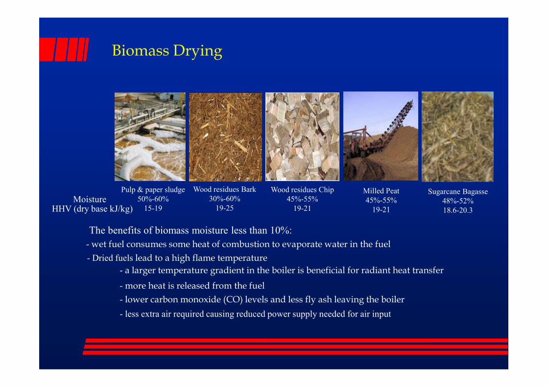
Biomass Drying
Pulp & paper sludge Wood residues Bark Wood residues Chip Milled Peat Sugarcane BagassePulp & paper sludge
50%-60%
15-19
Wood residues Bark
30%-60%
19-25
Wood residues Chip
45%-55%
19-21
Milled Peat
45%-55%
19-21
Sugarcane Bagasse
48%-52%
18.6-20.3
MoistureHHV (dry base kJ/kg)
The benefits of biomass moisture less than 10%:
- wet fuel consumes some heat of combustion to evaporate water in the fuel
- Dried fuels lead to a high flame temperature
- a larger temperature gradient in the boiler is beneficial for radiant heat transfer
- more heat is released from the fuel
- lower carbon monoxide (CO) levels and less fly ash leaving the boiler
- less extra air required causing reduced power supply needed for air input
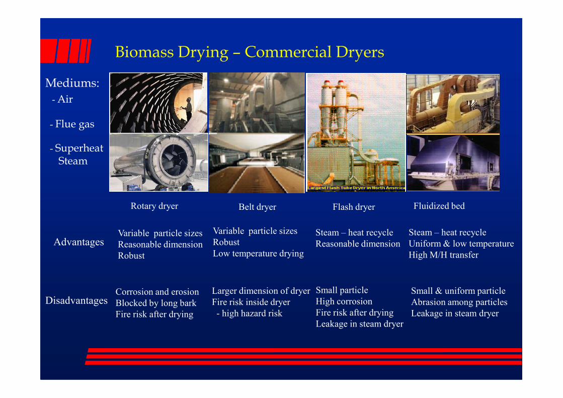
Biomass Drying – Commercial Dryers
Mediums:
- Air
- Flue gas
- SuperheatSteam
Rotary dryer Belt dryer Flash dryer Fluidized bed
Small particle
High corrosion
Fire risk after drying
Leakage in steam dryer
Variable particle sizes
Robust
Low temperature drying
Steam – heat recycle
Reasonable dimension
Steam – heat recycle
Uniform & low temperature
High M/H transfer
Variable particle sizes
Reasonable dimension
Robust
Larger dimension of dryer
Fire risk inside dryer
- high hazard risk
Corrosion and erosion
Blocked by long bark
Fire risk after drying
Small & uniform particle
Abrasion among particles
Leakage in steam dryer
Advantages
Disadvantages

Biomass Drying
Dryer types Manufactures Operation Parameters Costs
Rotary
Bacho Industry
Kirkenaer
MEC Company
Mitchell Dryers Ltd
Flue gas:
Temperature: 160-280 OC
Capacity: 800-7000 kg- H2O/h
Heat Consumption:
5.8 MJ/kg-H2O
include installation
$160-370/kg/h
$1.6-5.3 million
GEAFlue gas, steam:
Temperature: 150-700 OC include installation
Flash
GEA
DryCo
Einco
Temperature: 150-700 OC
Capacity: 6000-26000 kg- H2O/h
Heat Consumption:
0.4-1.0 MJ/kg-H2O
include installation
$330-860/kg/h
$3.5-10.6 million
Fluidized Bed Niro A/S
Steam:
Temperature: 190 OC
Capacity: 3600 kg- H2O/h
no installation:
$4.5-7 million
Belt
Swiss Combi
Bruks Klockner
Andritz Fiber
Air:
temperature:30-110 OC
Capacity: 500-40000 kg- H2O/h
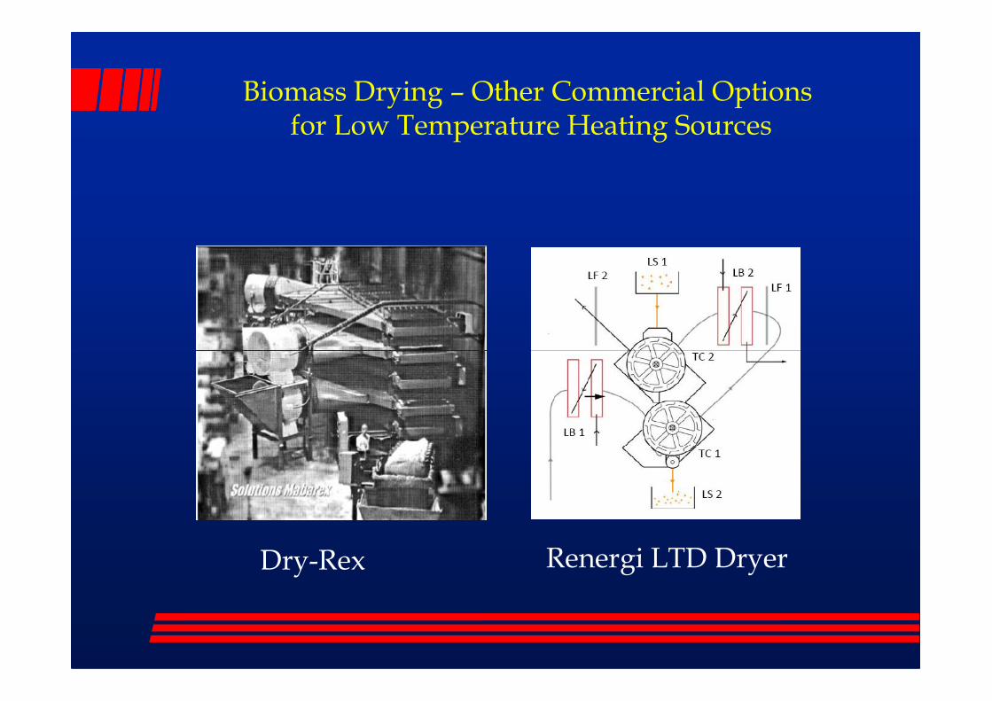
Biomass Drying – Other Commercial Options for Low Temperature Heating Sources
Renergi LTD DryerDry-Rex

Biomass Drying
Drying is an extra cost in process industries and power plants, even though this may be offset by smaller boiler, air emissions equipment and fuel handling equipment.
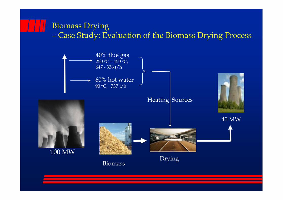
Biomass Drying– Case Study: Evaluation of the Biomass Drying Process
40% flue gas250 oC – 450 oC;647 - 336 t/h
60% hot water90 oC; 737 t/h
Heating Sources
100 MW
Biomass
Heating Sources
40 MW
Drying

Biomass Drying – Case Study
Mflue , HCf,in, Tf,in, Hf,in Mflue , HCf,out, Tf,out, Hf,out
Mwood, MCw,in, Tw,in, Hw,in Mwood, MCw,out, Tw,out, Hw,out
Mflue , Tf,,out
Dryer
Mass and Heat Balances:
Flue Gas Drying
MS, Ps,in, Ts,in, Hs,inMwat, Twat, Hwat
MS, Ps,out, Ts,out, Hs,out
Mwood, MCw,in,
Tw,in, Hw,in
Mwood, MCw,out,
Tw,out, Hw,out
Pre-heater
Dryer
R
Mflue , Tf,in
Mflue , Tf,,out
Steam Drying
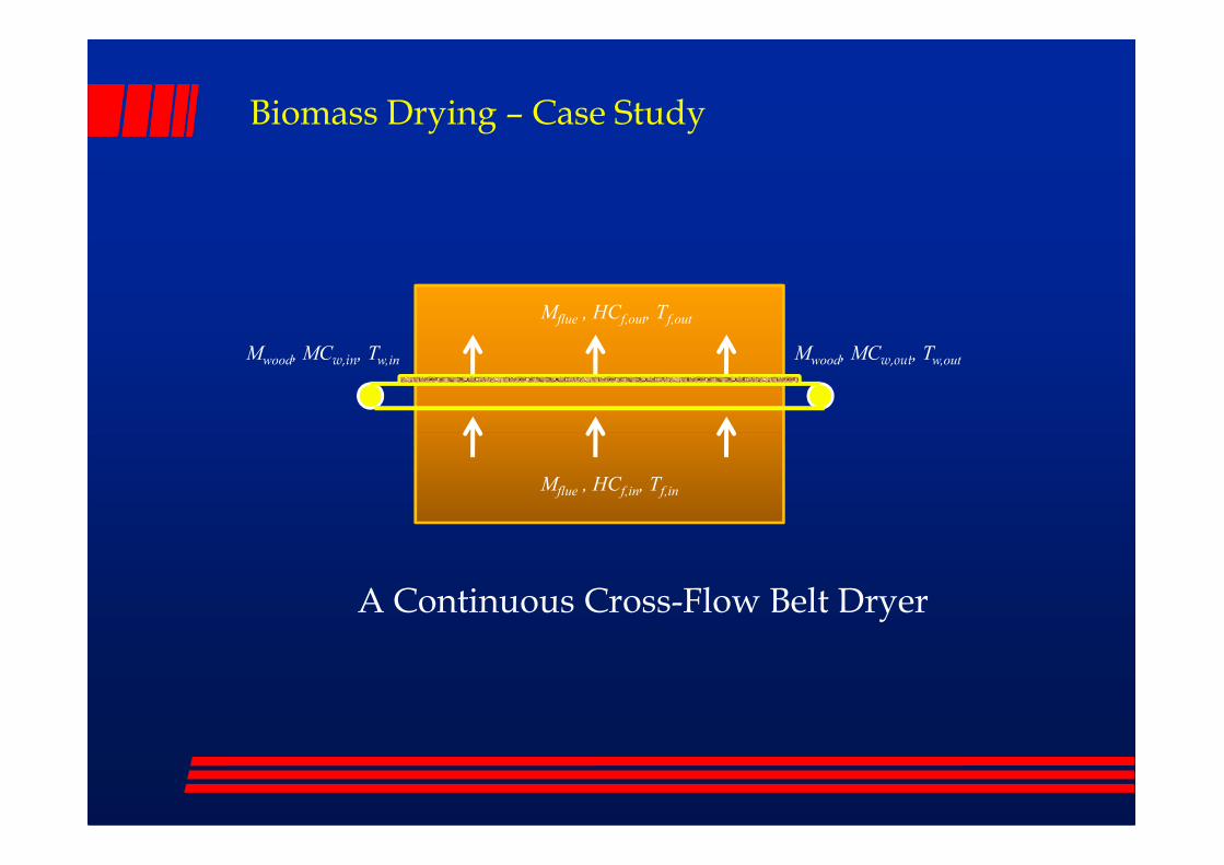
Biomass Drying – Case Study
Mflue , HCf,out, Tf,out
Mwood, MCw,in, Tw,in Mwood, MCw,out, Tw,out
Mflue , HCf,in, Tf,in
A Continuous Cross-Flow Belt Dryer

.)./(
)(40 (kg/s)M wood
bdkgMJvalueheatingfuel
MWplantpowerininputpower
−=
)MC-(MCMW(kg/s) outinwood ×=
Biomass Drying – Estimation of Water Evaporation
)MC-(MCMW(kg/s) outinwood ×=
Moisture change (wt%-wet)
initial, final (kg/s) (t/h)
0.6, 0.1 3.3339 12.0019
0.6, 0.2 3.0005 10.8017
0.6, 0.3 2.5718 9.2586
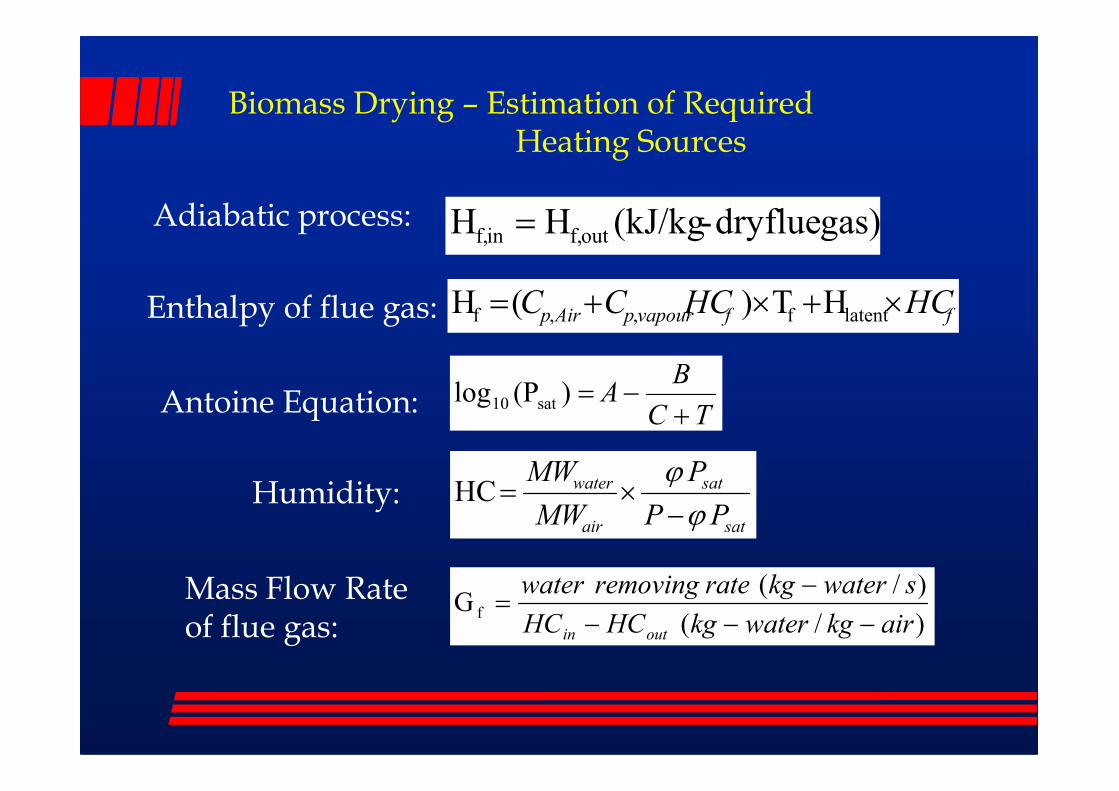
gas) fluedry -(kJ/kgHH outf,inf, =
Biomass Drying – Estimation of Required Heating Sources
Adiabatic process:
ffvapourpAirp HCHCCC ×+×+= latentf,,f HT) (HEnthalpy of flue gas:
BA
+−=)(Plog sat10Antoine Equation: TC
A+
−=)(Plog sat10Antoine Equation:
sat
sat
air
water
PP
P
MW
MW
ϕ
ϕ
−×=HCHumidity:
Mass Flow Rateof flue gas: )/(
)/(G f
airkgwaterkgHCHC
swaterkgrateremovingwater
outin −−−
−=
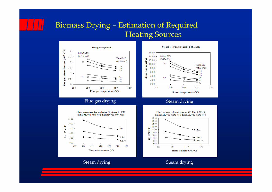
Biomass Drying – Estimation of Required Heating Sources
Flue gas drying Steam drying
Steam drying Steam drying
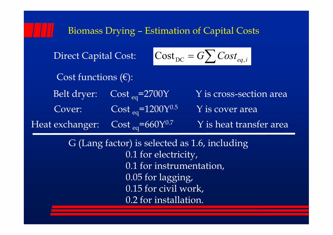
Biomass Drying – Estimation of Capital Costs
∑= ieqCostG ,DCCost
Belt dryer: Cost eq=2700Y Y is cross-section area
Cover: Cost eq=1200Y0.5 Y is cover area
Cost functions (€):
Direct Capital Cost:
Heat exchanger: Cost eq=660Y0.7 Y is heat transfer area
G (Lang factor) is selected as 1.6, including 0.1 for electricity, 0.1 for instrumentation, 0.05 for lagging, 0.15 for civil work,0.2 for installation.
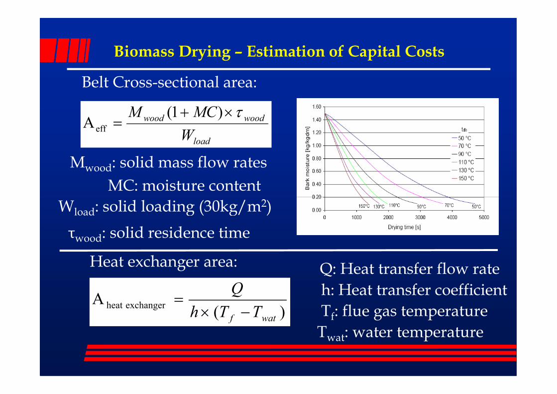
Biomass Drying – Estimation of Capital Costs
load
woodwood
W
MCM τ×+=
)1(A eff
Mwood: solid mass flow rates
MC: moisture content
W : solid loading (30kg/m2)
Belt Cross-sectional area:
Wload: solid loading (30kg/m2)
Heat exchanger area:
)(A exchangerheat
watf TTh
Q
−×=
τwood: solid residence time
Q: Heat transfer flow rate
h: Heat transfer coefficient
Tf: flue gas temperature
Twat: water temperature

Biomass Drying – Estimation of Capital Costs
Flue gas drying Steam drying

Biomass Drying – Estimation of Profitability
Capitalenancema C
C−
+
−= ∑
=
=
kt
0tt
intt
i)(1
C t)NPV(projec
Cmaintenance=0.05 CCapital
Ct= (HCsave - Q × HCflue gas) × τop
HCsave= Weva× Hlatent × HCfuel
HCflue gas: price of flue gas (0.5 €/GWH)
HCfuel: price of biomass fuel (6-20 €/MWH)
Weva: water evaporation rate (kg/s)
Hlatent: latent heat of water (kJ/kg)
Q: heating rate for water evaporation (kJ/s)
i: interest; t: year; τop: 8400 h/year

Biomass Drying – Estimation of Profitability
Flue gas drying
Initial MC=1.5 kg-w/kg-wood
Cumulative cash flow 10 year NPV
Final MC=0.1, 0.3 kg-w/kg-wood Final MC=0.1 kg-w/kg-woodFuel price = 14 €/MWH Fuel price = 14 €/MWH
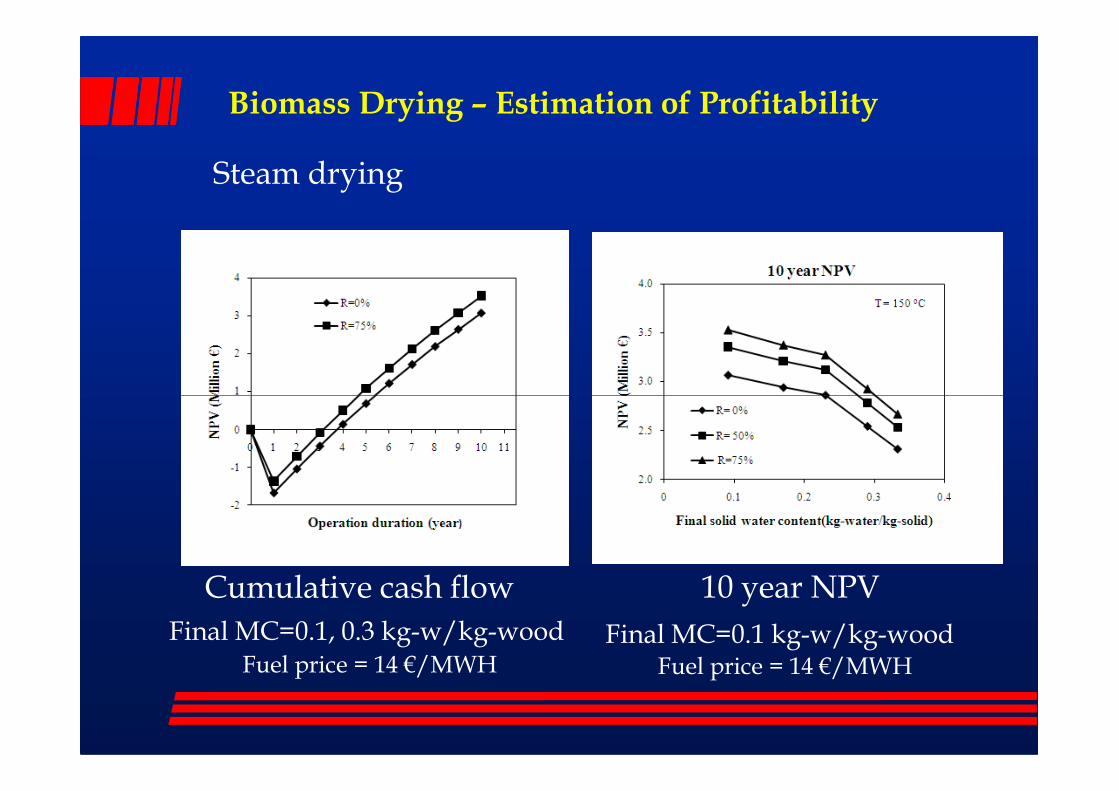
Biomass Drying – Estimation of Profitability
Steam drying
Cumulative cash flow 10 year NPV
Final MC=0.1, 0.3 kg-w/kg-wood Final MC=0.1 kg-w/kg-woodFuel price = 14 €/MWH Fuel price = 14 €/MWH
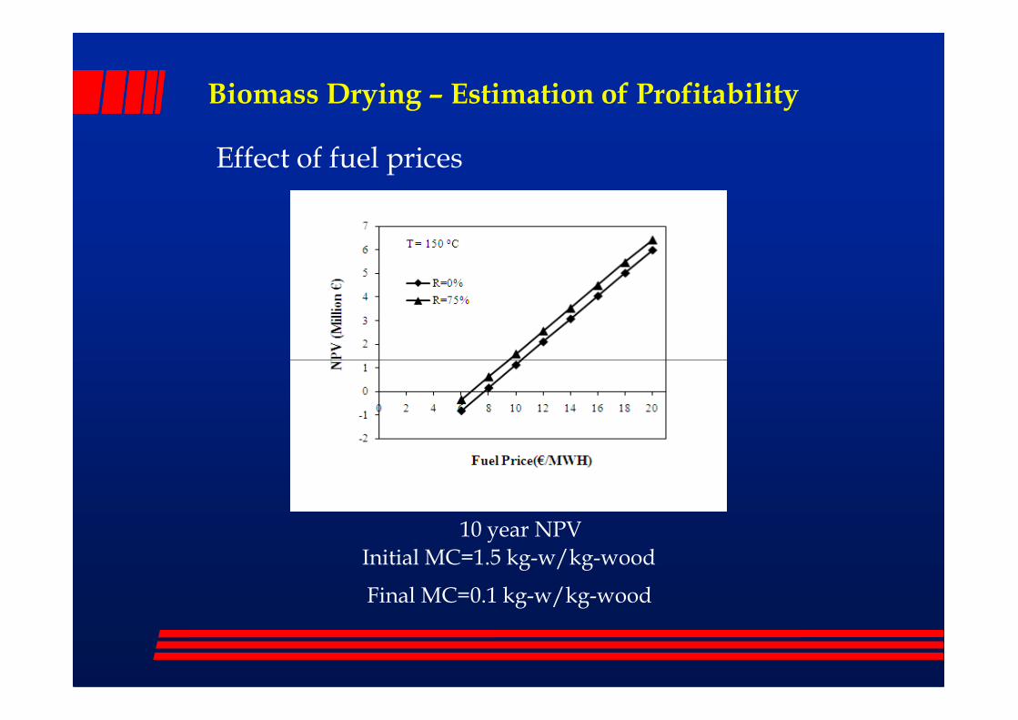
Biomass Drying – Estimation of Profitability
Effect of fuel prices
Initial MC=1.5 kg-w/kg-wood
Final MC=0.1 kg-w/kg-wood
10 year NPV
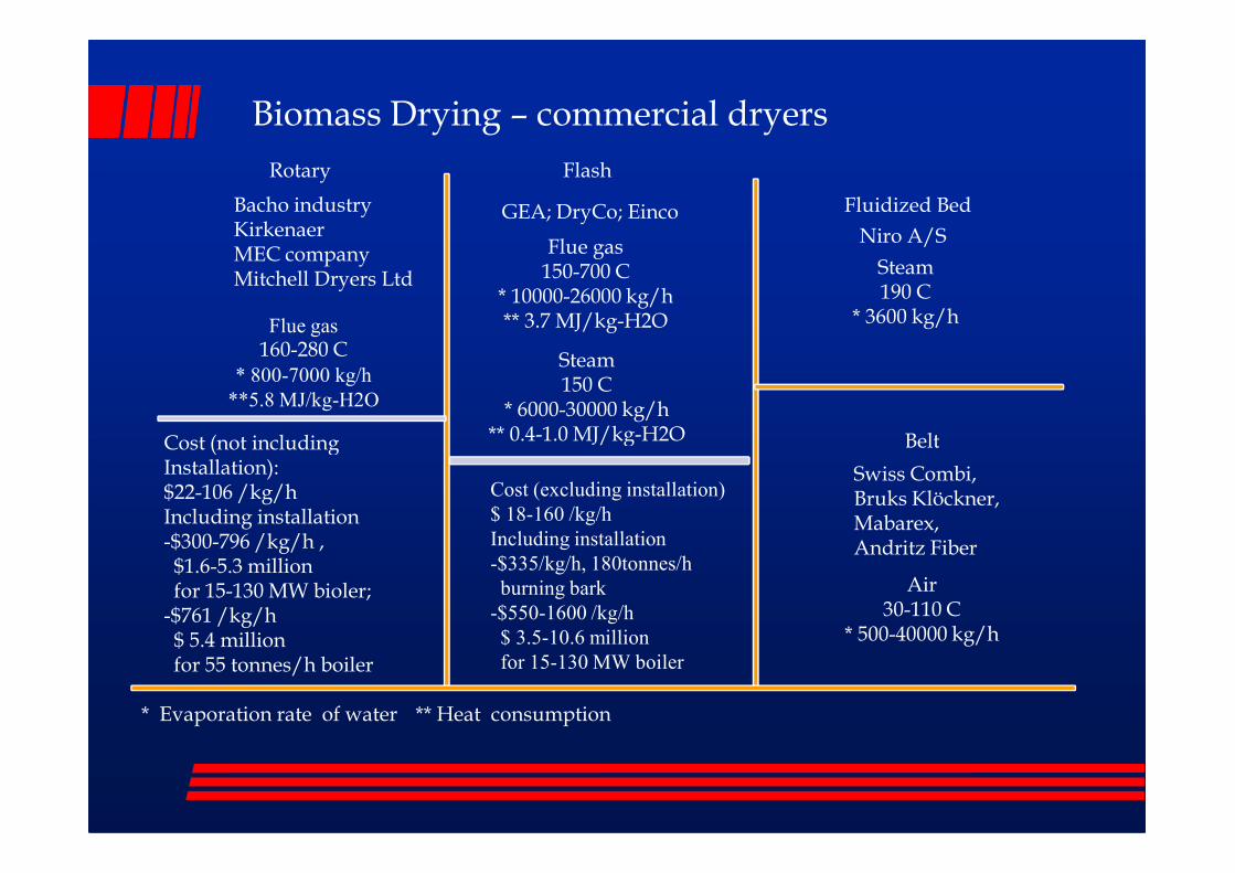
Bacho industryKirkenaerMEC companyMitchell Dryers Ltd
Rotary
Belt
Flash
GEA; DryCo; Einco
Flue gas150-700 C
* 10000-26000 kg/h** 3.7 MJ/kg-H2O
Steam150 C
* 6000-30000 kg/h** 0.4-1.0 MJ/kg-H2O
Fluidized Bed
Niro A/S
Steam190 C
* 3600 kg/hFlue gas160-280 C
* 800-7000 kg/h
**5.8 MJ/kg-H2O
Cost (not including
Biomass Drying – commercial dryers
* Evaporation rate of water ** Heat consumption
Belt
Swiss Combi, Bruks Klöckner, Mabarex, Andritz Fiber
** 0.4-1.0 MJ/kg-H2O
Air30-110 C
* 500-40000 kg/h
Cost (not includingInstallation):$22-106 /kg/h Including installation-$300-796 /kg/h ,$1.6-5.3 millionfor 15-130 MW bioler;
-$761 /kg/h$ 5.4 millionfor 55 tonnes/h boiler
Cost (excluding installation)
$ 18-160 /kg/h
Including installation
-$335/kg/h, 180tonnes/h
burning bark
-$550-1600 /kg/h
$ 3.5-10.6 million
for 15-130 MW boiler
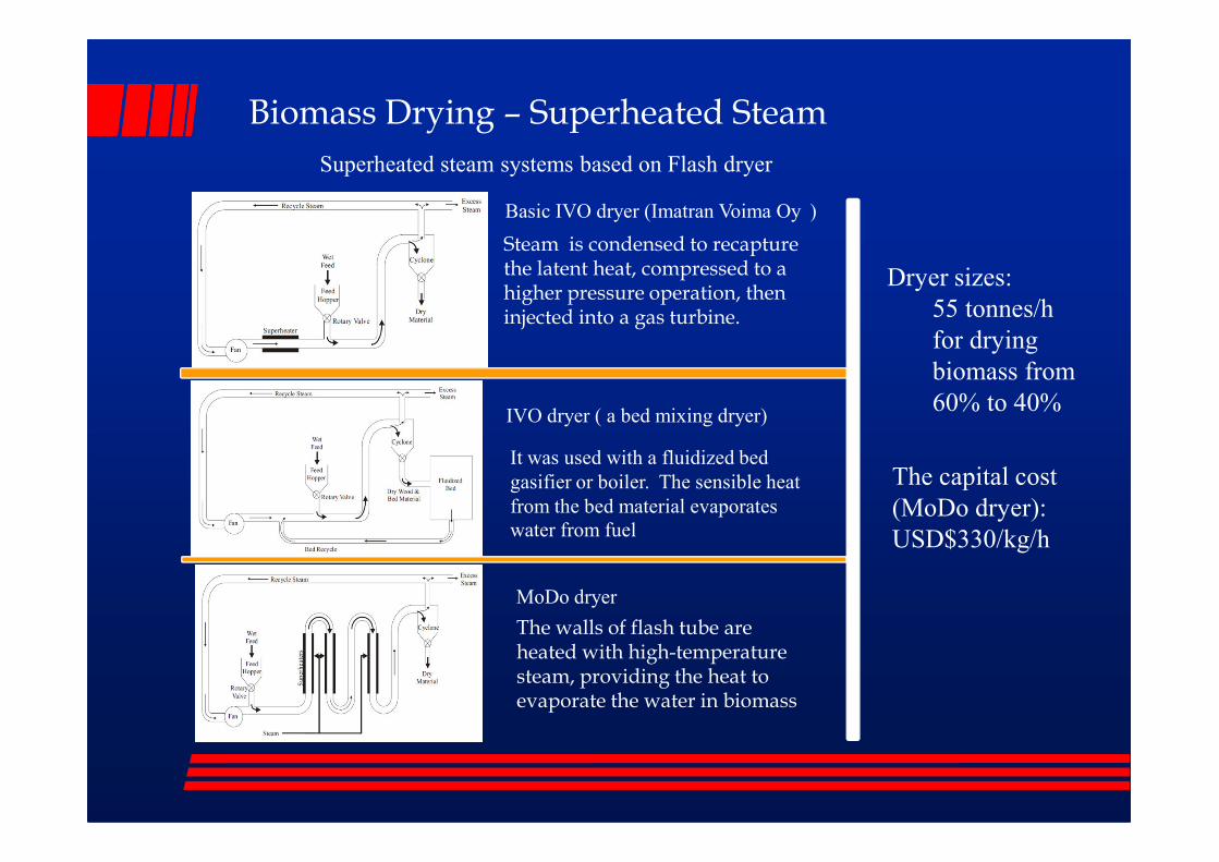
Biomass Drying – Superheated Steam
Basic IVO dryer (Imatran Voima Oy )
IVO dryer ( a bed mixing dryer)
Superheated steam systems based on Flash dryer
Steam is condensed to recapture the latent heat, compressed to a higher pressure operation, then injected into a gas turbine.
Dryer sizes:
55 tonnes/h
for drying
biomass from
60% to 40%
MoDo dryer
It was used with a fluidized bed
gasifier or boiler. The sensible heat
from the bed material evaporates water from fuel
The walls of flash tube are heated with high-temperature steam, providing the heat to evaporate the water in biomass
The capital cost
(MoDo dryer):
USD$330/kg/h

Biomass Drying – other options
Advantages:- high power density-reducing drying time- high energy efficiency, avoid warm up and cool down- improved quality, compared with conventional drying.- avoids combustible gas by- products, environmental friendly
Disadvantages:- not uniform dried (hot spot or cold spot)- penetration achievable, depended on biomass properties.- insufficient knowledge of the interaction between wood
Microwave dryer
- insufficient knowledge of the interaction between wood and process parameters as well as the higher investment expenses.
Supercritical CO2Advantages: - using CO2(green house gas)- low temperature (saving energy)- low fire risk- high quality (avoiding high temperature heating biomass)
Disadvantages:- high pressure equipmentand processes

Task3 Task3 -- Sheffield ; high efficiencySheffield ; high efficiency
� Novel technology
� Industrial condensing boilers
� Low temperature, < dew point
� Boiler design
� External system
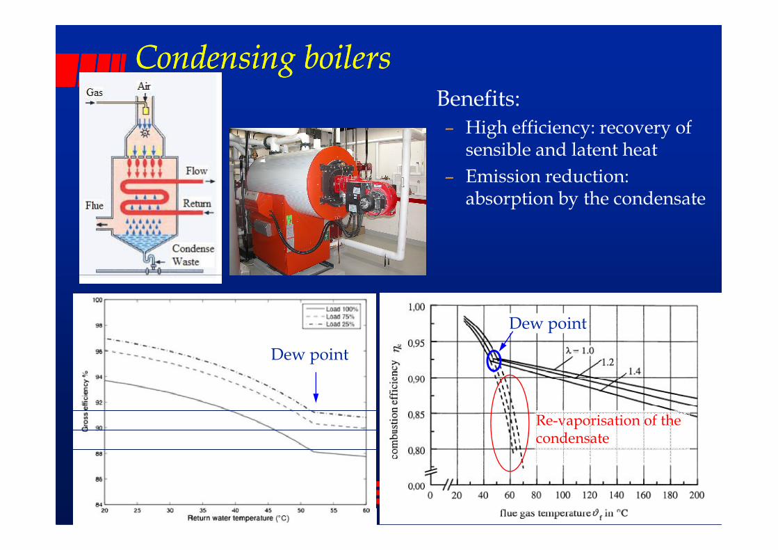
Condensing boilersCondensing boilers� Benefits:
– High efficiency: recovery of sensible and latent heat
– Emission reduction: absorption by the condensate
Dew point
Dew point
Re-vaporisation of the condensate
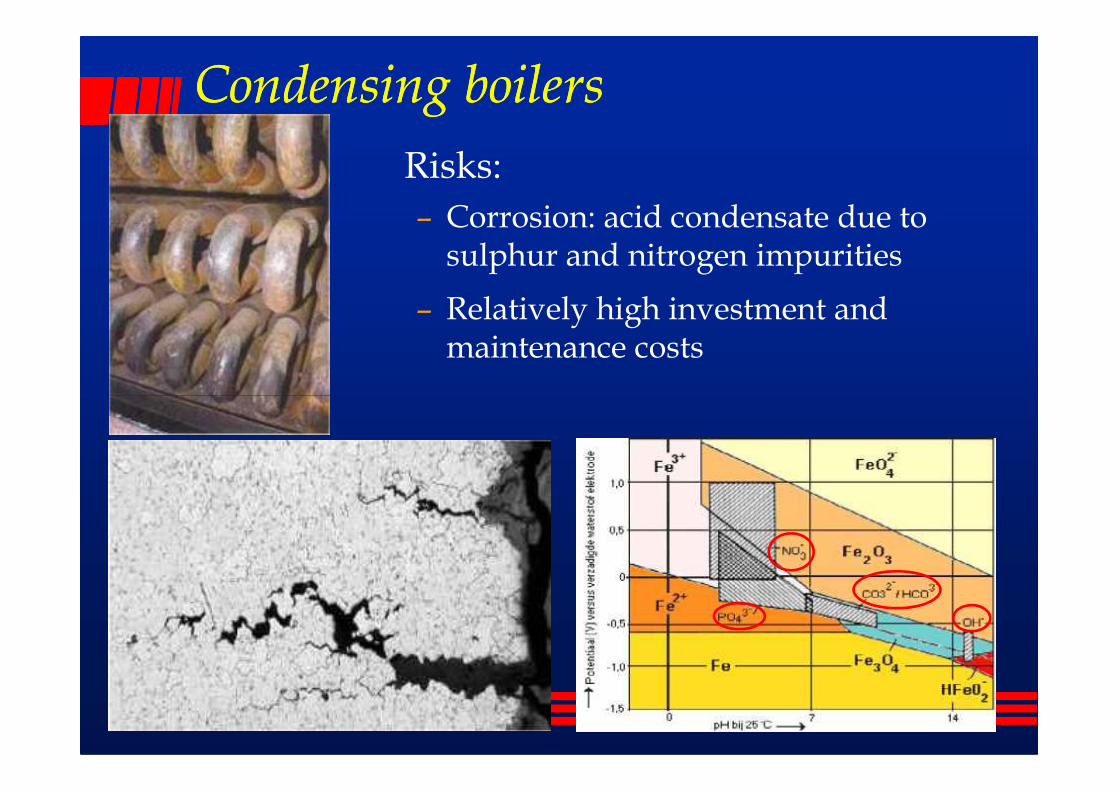
Condensing boilersCondensing boilers
� Risks:
– Corrosion: acid condensate due to sulphur and nitrogen impurities
– Relatively high investment and maintenance costs
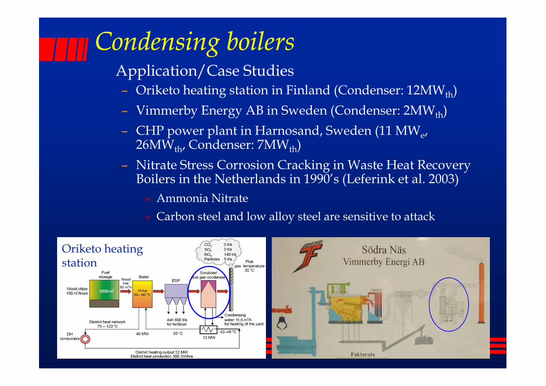
Condensing boilersCondensing boilers� Application/Case Studies
– Oriketo heating station in Finland (Condenser: 12MWth)
– Vimmerby Energy AB in Sweden (Condenser: 2MWth)
– CHP power plant in Harnosand, Sweden (11 MWe, 26MWth, Condenser: 7MWth)
– Nitrate Stress Corrosion Cracking in Waste Heat Recovery Boilers in the Netherlands in 1990’s (Leferink et al. 2003)
» Ammonia Nitrate» Ammonia Nitrate
» Carbon steel and low alloy steel are sensitive to attack
Oriketo heating station

Condensing boilers with Radiator & floor heatingCondensing boilers with Radiator & floor heating
� Return water from a heating system should be 30-50°C, well below the dew point of flue gas
� A floor heating system or large surface area radiator is required.

Condensing boilers with a heat pumpCondensing boilers with a heat pump
� A heat pump can be used between the condenser and the hot return water– Conventional electrically driven compression heat pump
– An absorption heat pump


Thermoacoustic EngineThermoacoustic Engine� Thermoacoustic engines of which nearly all are thermoacoustic
stirling engines;
� It is a technology that uses high-amplitude sound waves in a pressurized gas to pump heat from one place to another;
� or uses a heat temperature difference to induce sound, which can be converted to electricity with high efficiency, with a (piezoelectric) loudspeaker;(piezoelectric) loudspeaker;
� The most efficient thermoacoustic devices built to date have an efficiency approaching 40% of the Carnot limit, or about 20% to 30% overall (depending on the heat engine temperatures).
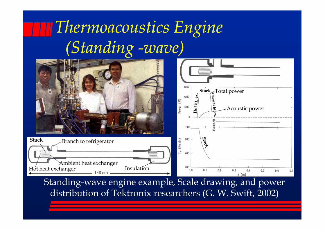
Thermoacoustics Engine Thermoacoustics Engine (Standing (Standing --wave)wave)
Stack Total power
Acoustic power
Standing-wave engine example, Scale drawing, and power distribution of Tektronix researchers (G. W. Swift, 2002)
Branch to refrigerator
InsulationAmbient heat exchanger
Stack
Hot heat exchanger138 cm
Branch
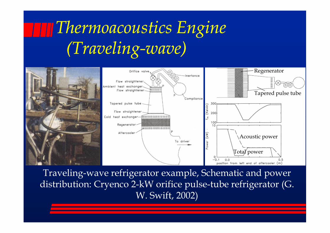
Thermoacoustics Engine Thermoacoustics Engine (Traveling(Traveling--wave)wave)
Tapered pulse tube
Regenerator
Traveling-wave refrigerator example, Schematic and power distribution: Cryenco 2-kW orifice pulse-tube refrigerator (G.
W. Swift, 2002)
Acoustic power
Total power
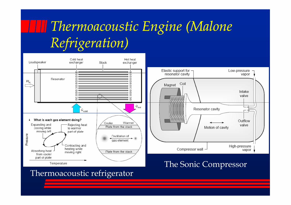
Thermoacoustic Engine (Malone Thermoacoustic Engine (Malone Refrigeration)Refrigeration)
Thermoacoustic refrigeratorThe Sonic Compressor

Stakeholder InputStakeholder Input
� Industrial Partners
– Other industrial participants
– Co-opted partners– Co-opted partners

Task 1. National sources of low grade heat available from the process industry- Led by Newcastle University
Research Tasks
Task 2. Identification of potential uses of the energy and their relative location. - Led by Newcastle University.
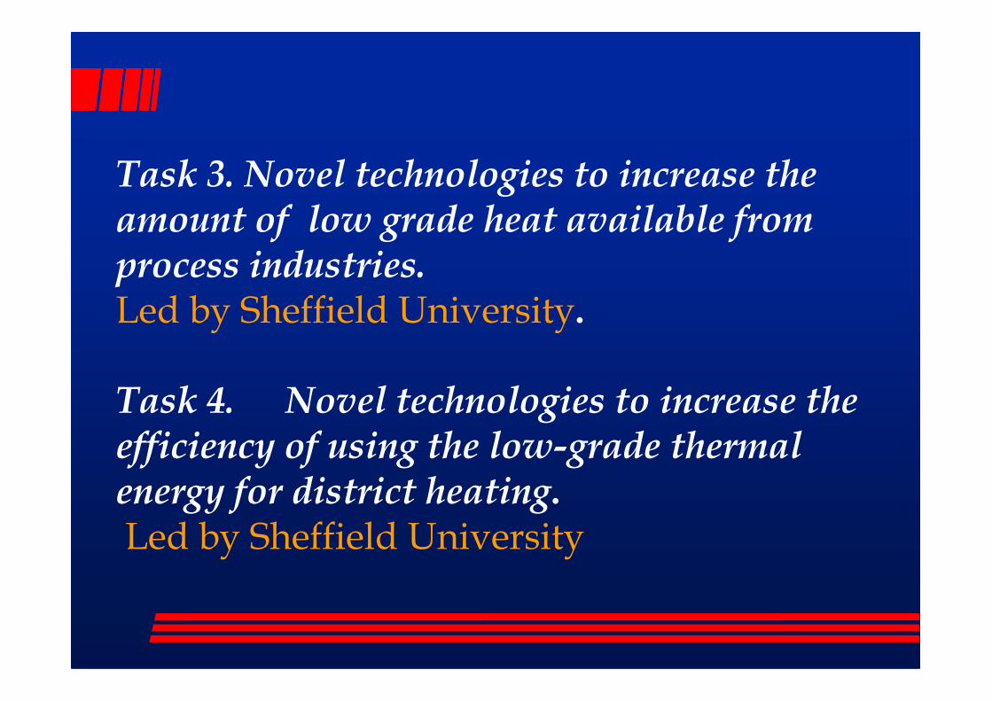
Task 3. Novel technologies to increase the amount of low grade heat available from process industries.Led by Sheffield University.
Task 4. Novel technologies to increase the efficiency of using the low-grade thermal energy for district heating. Led by Sheffield University
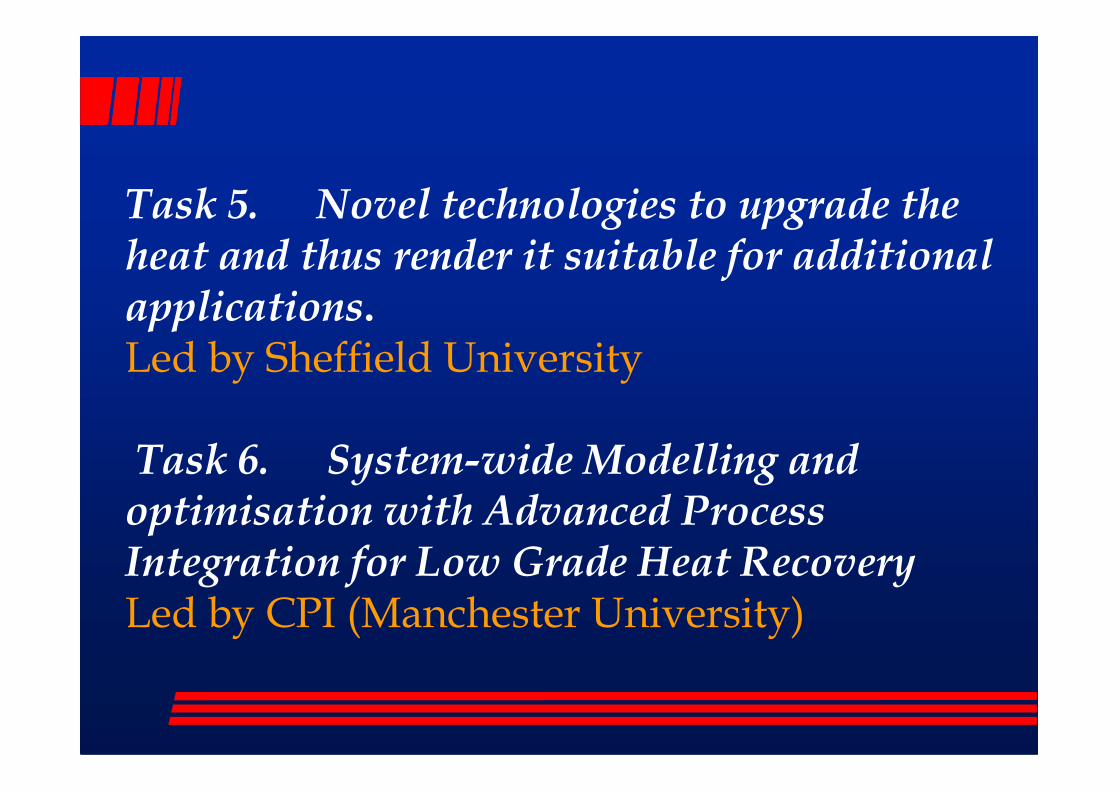
Task 5. Novel technologies to upgrade the heat and thus render it suitable for additional applications. Led by Sheffield University
Task 6. System-wide Modelling and optimisation with Advanced Process Integration for Low Grade Heat RecoveryLed by CPI (Manchester University)
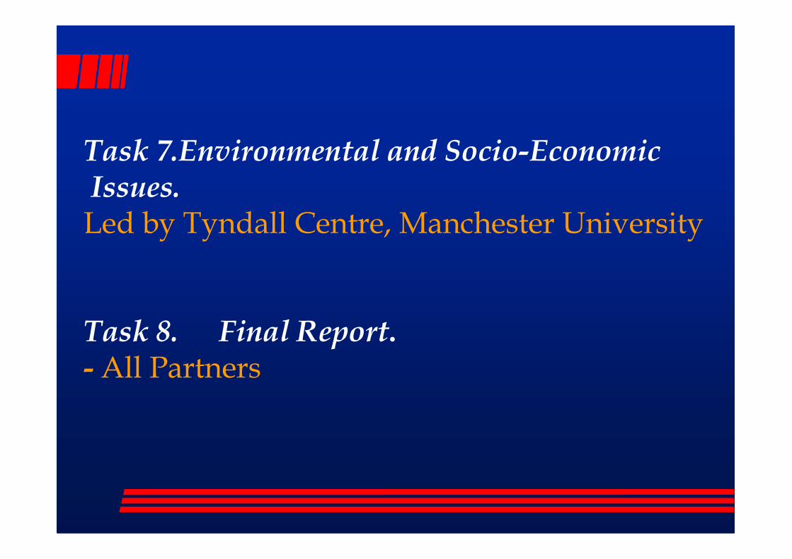
Task 7.Environmental and Socio-EconomicIssues. Led by Tyndall Centre, Manchester University
Task 8. Final Report.- All Partners

Danish Integrated Boilers/Combined Cycle CHP network of units
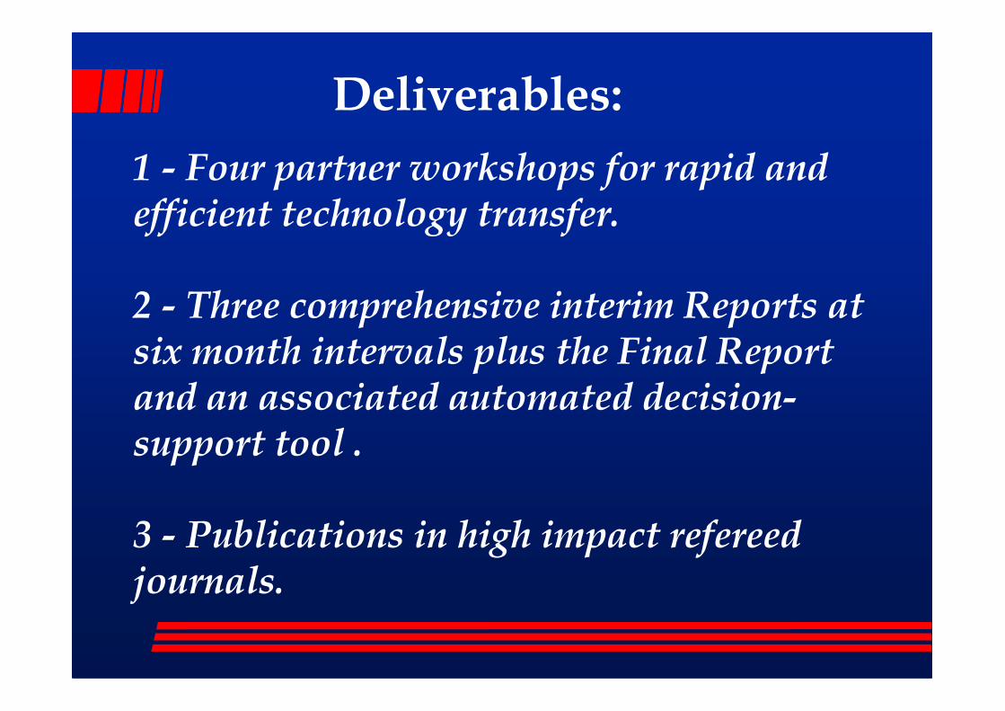
1 - Four partner workshops for rapid and efficient technology transfer.
2 - Three comprehensive interim Reports at six month intervals plus the Final Report
Deliverables:
six month intervals plus the Final Report and an associated automated decision-support tool .
3 - Publications in high impact refereed journals.

4 – ‘Exploitation’ of the concurrent and future EPSRC Network and web site .
5 - Dissemination of policy-relevant 5 - Dissemination of policy-relevant recommendations to stakeholders in an appropriate form. It is envisaged that the Network will be the major route for wider dissemination.

Project Work Plan
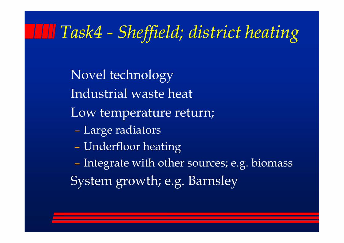
Task4 Task4 -- Sheffield; district heatingSheffield; district heating
� Novel technology
� Industrial waste heat
� Low temperature return;
– Large radiators
– Underfloor heating
– Integrate with other sources; e.g. biomass
� System growth; e.g. Barnsley
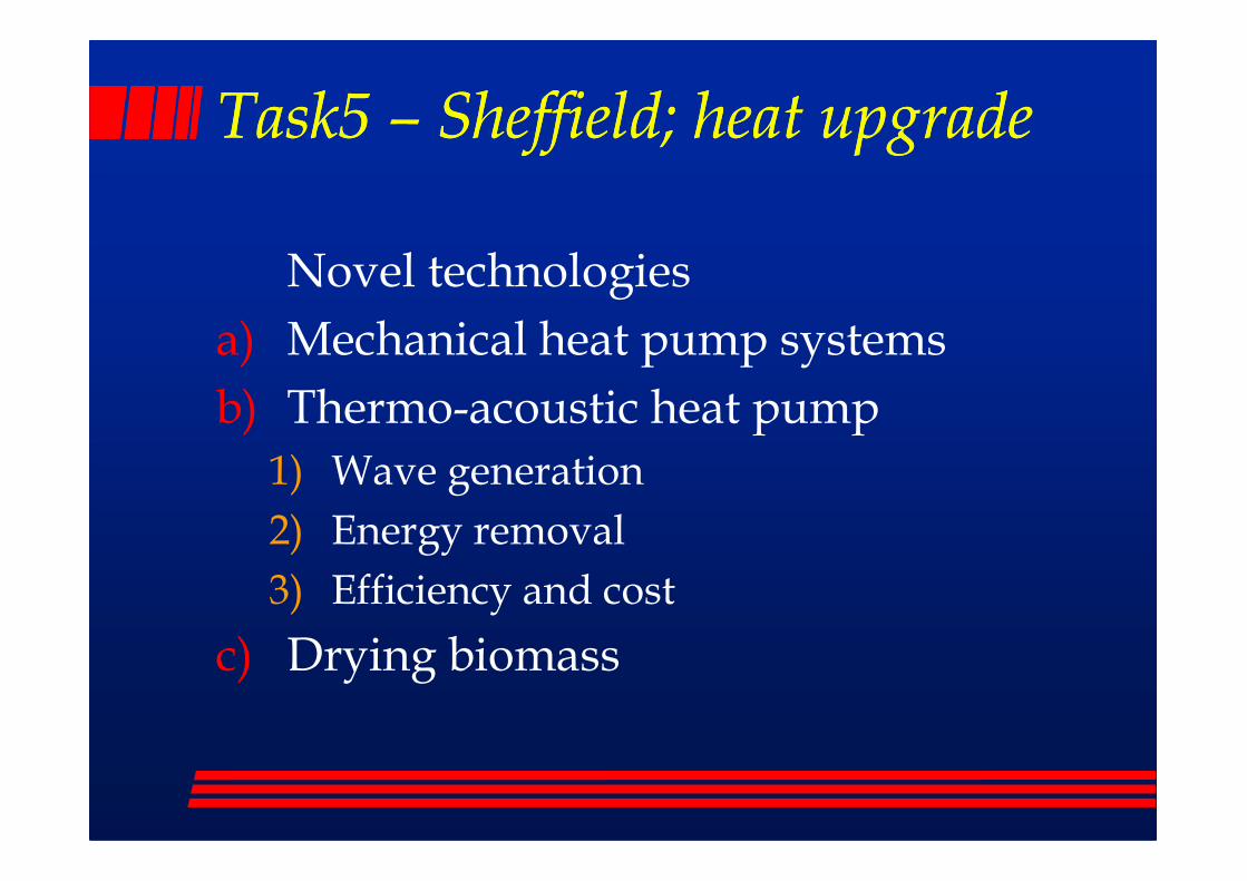
Task5 Task5 –– Sheffield; heat upgradeSheffield; heat upgrade
� Novel technologies
a) Mechanical heat pump systems
b) Thermo-acoustic heat pump
1) Wave generation
2) Energy removal
3) Efficiency and cost
c) Drying biomass


![Welcome [themedicinemaker.com]...industry with Abbott Laboratories (ABBVIE), Evonik Degussa and Piramal Healthcare. Joe holds B.S. a in Chemistry and Biology from Loyola University,](https://static.fdocuments.us/doc/165x107/5f27bfd45033e907d82b7da4/welcome-industry-with-abbott-laboratories-abbvie-evonik-degussa-and-piramal.jpg)