Review of catalyst materials and catalytic steam reforming reactions in SOFC anodes
11
INTERNATIONAL JOURNAL OF ENERGY RESEARCH Int. J. Energy Res. 2011; 35:1340–1350 Published online 8 June 2011 in Wiley Online Library (wileyonlinelibrary.com). DOI: 10.1002/er.1875 Review of catalyst materials and catalytic steam reforming reactions in SOFC anodes Martin Andersson ,y , Hedvig Paradis, Jinliang Yuan and Bengt Sunde ´n Department of Energy Sciences, Faculty of Engineering, Lund University, Box 118, 221 00 Lund, Sweden SUMMARY It is expected that fuel cells will play a significant role in the future sustainable energy system, because of their high energy efficiency and possibility to use renewable fuels. Fuels, such as biogas, can be produced locally close to the customers. The improvement for FCs during the last years has been fast, but the technology is still in the early phases of development, in terms of cost, stability and market sharing. The reforming reaction of hydrocarbons (e.g., methane) is significant for an effective solid oxide fuel cell operation. This reaction could either be described by global kinetics or by elementary surface reaction kinetics. When a global approach is applied, the reaction rates depend on temperature, partial pressures, activation energy and the pre-exponential factor. Note that the last two mentioned parameters are normally calculated from experimental data. Different detailed reaction mechanisms (considering elementary surface kinetics) are developed, but there is a disagreement considering the involved reaction pathways, rate-limiting steps and intermediate species. It is found that detailed kinetics of the reforming reaction is important for design and development of new effective catalytic materials. A thermodynamic analysis tells that nickel and ruthenium are suitable catalytic materials for the methane reforming reactions. Copyright r 2011 John Wiley & Sons, Ltd. KEY WORDS SOFC; internal reforming; catalytic activity; reaction pathway; catalyst Correspondence *Martin Andersson, Department of Energy Sciences, Faculty of Engineering, Lund University, Box 118, 221 00 Lund, Sweden. y E-mail: [email protected] Received 27 September 2010; Revised 27 January 2011; Accepted 24 March 2011 1. INTRODUCTION Fuel cells (FCs) directly convert the free energy of a chemical reactant to electrical power and heat. This is different from a conventional thermal power engine, where the fuel is oxidized in a combustion process combined with a conversion process (thermal– mechanical–electrical energy), which takes place after the combustion. FCs do not store energy as batteries do [1]. The FC is not a new invention, since the electrochemical process was discovered already in 1838–1839 [2]. Among various types of FCs, the solid oxide fuel cell (SOFC) has attained significant interests due to its high efficiency and low emissions of pollutants to the environment. High temperature (HT) operation offers SOFC many advantages, such as high electrochemical reaction rate, flexibility of using various fuels and toleration of impurities [3]. The SOFC electrolyte is non-porous ceramic, nor- mally Y 2 O 3 stabilized ZrO 2 (YSZ). At an operating temperature between 600 and 10001C, the ceramic electrolyte becomes non-conductive for electrons, but conductive to oxygen ions. Cathodes are mostly made from electronically conducting oxides or mixed elec- tronically conducting and ion-conduction ceramics. The anode consists normally of nickel/yttria stabilized zirconia (Ni/YSZ) cermet. This composition enables internal reforming (IR) reactions of methane, due to the catalyst material characteristics. SOFCs can be designed with planar, tubular or monolithic structures. The planar configuration is normally more compact, compared to the tubular one, i.e. a higher specific power per volume is achieved. The tubular and planar SOFCs can be either electrolyte-, anode-, cathode- or metal supported. An electrolyte-supported SOFC has thin anode and cathode ($50 mm), and the thickness of the electrolyte is more than 100 mm. This design works preferably at temperatures around 10001C. In an electrode-supported SOFC, either the anode or the cathode is thick enough to serve as the supporting substrate for cell fabrication, normally between 0.3 and 1.5 mm. The electrolyte is in this configuration very Copyright r 2011 John Wiley & Sons, Ltd.
-
Upload
martin-andersson -
Category
Documents
-
view
212 -
download
0
Transcript of Review of catalyst materials and catalytic steam reforming reactions in SOFC anodes

INTERNATIONAL JOURNAL OF ENERGY RESEARCH
Int. J. Energy Res. 2011; 35:1340–1350
Published online 8 June 2011 in Wiley Online Library (wileyonlinelibrary.com). DOI: 10.1002/er.1875
Review of catalyst materials and catalytic steamreforming reactions in SOFC anodes
Martin Andersson�,y, Hedvig Paradis, Jinliang Yuan and Bengt Sunden
Department of Energy Sciences, Faculty of Engineering, Lund University, Box 118, 221 00 Lund, Sweden
SUMMARY
It is expected that fuel cells will play a significant role in the future sustainable energy system, because of their highenergy efficiency and possibility to use renewable fuels. Fuels, such as biogas, can be produced locally close to thecustomers. The improvement for FCs during the last years has been fast, but the technology is still in the earlyphases of development, in terms of cost, stability and market sharing.The reforming reaction of hydrocarbons (e.g., methane) is significant for an effective solid oxide fuel cell
operation. This reaction could either be described by global kinetics or by elementary surface reaction kinetics.When a global approach is applied, the reaction rates depend on temperature, partial pressures, activation energyand the pre-exponential factor. Note that the last two mentioned parameters are normally calculated fromexperimental data. Different detailed reaction mechanisms (considering elementary surface kinetics) are developed,but there is a disagreement considering the involved reaction pathways, rate-limiting steps and intermediatespecies. It is found that detailed kinetics of the reforming reaction is important for design and development of neweffective catalytic materials. A thermodynamic analysis tells that nickel and ruthenium are suitable catalyticmaterials for the methane reforming reactions. Copyright r 2011 John Wiley & Sons, Ltd.
KEY WORDS
SOFC; internal reforming; catalytic activity; reaction pathway; catalyst
Correspondence
*Martin Andersson, Department of Energy Sciences, Faculty of Engineering, Lund University, Box 118, 221 00 Lund, Sweden.yE-mail: [email protected]
Received 27 September 2010; Revised 27 January 2011; Accepted 24 March 2011
1. INTRODUCTION
Fuel cells (FCs) directly convert the free energy of
a chemical reactant to electrical power and heat.
This is different from a conventional thermal power
engine, where the fuel is oxidized in a combustion
process combined with a conversion process (thermal–
mechanical–electrical energy), which takes place after
the combustion. FCs do not store energy as batteries
do [1]. The FC is not a new invention, since the
electrochemical process was discovered already in
1838–1839 [2]. Among various types of FCs, the solid
oxide fuel cell (SOFC) has attained significant interests
due to its high efficiency and low emissions of
pollutants to the environment. High temperature
(HT) operation offers SOFC many advantages, such
as high electrochemical reaction rate, flexibility of
using various fuels and toleration of impurities [3].
The SOFC electrolyte is non-porous ceramic, nor-
mally Y2O3 stabilized ZrO2 (YSZ). At an operating
temperature between 600 and 10001C, the ceramic
electrolyte becomes non-conductive for electrons, but
conductive to oxygen ions. Cathodes are mostly made
from electronically conducting oxides or mixed elec-
tronically conducting and ion-conduction ceramics.
The anode consists normally of nickel/yttria stabilized
zirconia (Ni/YSZ) cermet. This composition enables
internal reforming (IR) reactions of methane, due to
the catalyst material characteristics. SOFCs can be
designed with planar, tubular or monolithic structures.
The planar configuration is normally more compact,
compared to the tubular one, i.e. a higher specific
power per volume is achieved. The tubular and planar
SOFCs can be either electrolyte-, anode-, cathode- or
metal supported. An electrolyte-supported SOFC has
thin anode and cathode (�50 mm), and the thickness of
the electrolyte is more than 100 mm. This design works
preferably at temperatures around 10001C. In an
electrode-supported SOFC, either the anode or the
cathode is thick enough to serve as the supporting
substrate for cell fabrication, normally between 0.3 and
1.5mm. The electrolyte is in this configuration very
Copyright r 2011 John Wiley & Sons, Ltd.

thin, and the operating temperature can be reduced to
an intermediate temperature (IT), i.e. 600–8001C [4].
SOFCs can work with a variety of fuels, e.g. hy-
drogen, carbon monoxide, methane and combinations
of these [5,6]. Oxygen is reduced in the cathode
(Equation (1)). The oxygen ions are transported
through the electrolyte, but the electrons are prevented
to pass through the electrolyte. The electrochemical
reactions (Equations (2) and (3)) take place at the
anodic three-phase boundary (TPB). Methane needs to
be reformed (Equation (4)) before the electrochemical
reactions [7]. Carbon monoxide can be oxidized in
the electrochemical reaction (Equation (3)), but can
also react with water (Equation (5)). The reactions
described here are the overall reactions, more detailed
reaction mechanisms are discussed in Section 4.
O214e� , 2O2� ð1Þ
H21O2� , H2O12e� ð2Þ
CO1O2� , CO212e� ð3Þ
CH41H2O, 3H21CO ð4Þ
CO1H2O, H21CO2 ð5Þ
The aim of this work is to review the state-of-the-art
for catalyst materials and models of the methane
reforming reactions that occur within a SOFC. The
global kinetic schemes as well as the elementary sur-
face reaction kinetics are studied. Metals suitable for
the catalysts of the methane steam-reforming reactions
are compared. Different reaction mechanisms, includ-
ing comparison of surface coverages, are outlined and
discussed.
2. INTERNAL REFORMINGREACTIONS
The reforming reactions (Equations (4) and (5)) in
SOFC systems can be conducted both externally and
internally. The external reforming, such as the pre-
reformer in a SOFC system, indicates that the reformer
is placed outside the cell, which is possible for all types
of FCs. The IR refers to that the reforming reactions
occur within the cell. A pre-reformer needs extra
steam, since it cannot directly use the steam generated
in the electrochemical reactions. The IR can be direct
or indirect. In the direct internal reforming (DIR)
approach, the reforming processes occur together with
the electrochemical reactions within the anode. In the
indirect internal reforming (IIR) approach, the reform-
ing reactions appear in a reformer (within the cell) in
close contact with the anode where the exothermic
electrochemical reactions take place. The IR reactions
decrease the requirement for cell cooling (less surplus
of air). Less steam is needed and finally it offers
advantages with respect to the capital cost. Up to half
of the heat produced by the electrochemical reactions
could be ‘consumed’ by the steam reforming process
(Equation (4)). This would improve the system
electrical efficiency [8,9].
The probability for carbon depositions depends on
the steam-to-carbon ratio and on the catalytic com-
position [10,11]. It has been well established that the
key reactions occur over a surface layer of nickel
particles. If a layer of carbon is allowed to build up and
attach to a nickel crystallite rapid catalyst breakdown
can occur, due to the coke formation. It should be
noted that hydrocarbons with a longer carbon chain
than methane have a higher propensity for the
carbon deposition [10]. The risk of carbon deposition
can be decreased if the pre-reforming is carried out
before the cell, or the anode structure or configuration
is modified:
� Complete or partial replacement of doped zirco-
nia with doped ceria or ceria-zirconia possessing a
higher lattice oxygen reactivity/mobility. This can
be combined with complete or partial replacement
of Ni with an electron conductor that does not
catalyze carbon formation, such as Cu [11,12].
Anodes based on Cu-Co have been found to
reduce the risk for carbon formation [11].
� Replacement of doped zirconia by complex
perovskites with their doping by metals active in
the steam reforming reaction [12].
� Complete or partial replacement of Ni by
precious metals in cermets with complex perovs-
kites or doped zirconia as oxide phases [12].
It should be noted that cells with Cu-CeO2-YSZ
anodes demonstrate comparable performance when
operating on CO or syngas as on H2, for Ni-YSZ the
performance is significantly lower when operating on
CO or syngas. It has also been shown that adding Co
to Cu-CeO2-YSZ improves the performance [13].
When steam is used as oxidant, i.e. for methane steam
reforming and for water–gas shift reaction, the reac-
tion rates for ceria-supported metals can be scientifi-
cally higher than that for ceria or the transition metal
alone, due to interactions between the support and the
transition metal [14].
In a conventional HT SOFC the endothermic steam
reforming reaction is very fast. This can result in a
sharp temperature drop at the inlet of the stack. This
temperature gradient results in thermal tensions, which
in the worst case causes mechanical failure of the cells
[8]. The problem of the tensions and the big tempera-
ture gradient close to the inlet region could be solved
with different approaches:
� Lowering the operating temperature to an inter-
mediate range to reduce the steam reforming
reaction rates (Equation (4)) [15].
Catalyst materials and catalytic steam reforming M. Andersson et al.
Int. J. Energy Res. 2011; 35:1340–1350 r 2011 John Wiley & Sons, Ltd.
DOI: 10.1002/er
1341

� Recycling a part of the anode exhaust gas
to obtain a dilution of the fuel [8].
� The anode material can be designed with the aim
of a decreased steam reforming activity. Until now
these new SOFC materials, such as perovskite
oxides or cermets containing iron or copper, have
too low electrical conductivity or electrocatalytic
activity to meet real world requirements [8].
3. GLOBAL REACTION KINETICS
Several kinetic expressions considering the steam
reforming reaction have been developed and published
in the literature. The reaction order varies significantly
between the schemes, in terms of orders of methane
and water (m and n in Equation (6)), see [1] for typical
values. The reaction order of methane (m) varies
between 0.85 and 1.4. For water, both negative and
positive values for reaction order (n) exist. However, it
has been shown that all these findings could be correct
for the chosen operating conditions of the experiments.
A small steam-to-carbon (SC) ratio gives positive
reaction order of water. SC in the order of 2 yields the
reaction orders of water close to zero, and high SC
gives negative values [16]. Experimental work has
shown that it is possible to change the steam reforming
reaction orders by modifying the anode, for example,
m increased from 0.85 to 1.4 and n decreased from
�0.35 to �0.8 when other compounds are added to the
Ni-YSZ anode [15]. As revealed in [1], comparison
with experimental data is rare, but it is worthwhile to
note that the reaction orders (m and n) usually
originate from fitting experimental data to a kinetic
expression.
rr;Arr ¼ k � pmCH4� pnH2O
� exp�Ea
R � T
� �ð6Þ
where rr is the reaction rate of the steam reforming
reaction (Equation (4)), p the partial pressure, R the
ideal gas constant and T the temperature. The unit for
the reaction rate is dependent on the pre-exponential
factor. Normally, the unit for the methane steam
reforming reaction rate is in mol s�1m�2, and can then
be converted to mol s�1m�3 after multiplying it with
the ratio between the active surface area to the volume
(AV, in m2m�3). The range for the AV (related to
catalytic kinetic reactions) varies in the literature
between 1� 105m2m�3 [17] and 2.2� 106m2m�3 [18]
for SOFC anodes. For example, the measured ratio for
Ni/YSZ material developed for SOFC anodes (with a
pore size of 225 nm) is 70� 106m2m�3 [19]. Note that
not all the surfaces are available for the catalytic
reactions, due to the distribution of the catalysts, non-
available pores and mass transfer limitations among
others. An AV of 2.2� 106m2m�3 corresponds to
3.1% of the total Ni/YSZ surface area in this specific
case. The kinetic expression for the methane steam
reforming in Equation (6) is of Arrhenius type, and can
be compared to an expression of the Langmuir–Hin-
shelwood type, as shown in Equation (7) [20]:
rr;Lang: ¼ k �pCH4
� pH2O � KCH4� KH2O
ð11pCH4� KCH4
1pH2O � KH2OÞ2ð7Þ
The kinetic expressions, in Equations (6) and (7),
can be compared to the equilibrium approach in
Equation (8) [16]:
rr;eq ¼ k � pCH4� pH2O � 1�
pCO � p3H2
Ke;STR � pCH4� pH2O
!ð8Þ
where Ke is the equilibrium constant. The reaction
orders in Equation (8) are the same as the molar pro-
portions for the respective gas species in the global
chemical reaction (1 for both methane and water for
the forward reaction, and 3 for hydrogen and 1 for
carbon monoxide for the backward reaction).
Different approaches for defining the water–gas shift
reaction (Equation (5)) can be found in the literature:
� Global catalytic reaction mechanism that con-
siders reaction in the anode only [21,22].
� Global catalytic reaction mechanism that con-
siders reaction in the anode and gas reaction in
the fuel channel [15,18].
� A more advanced reaction mechanism that
includes the catalytic surface reaction kinetics
for the steam reforming, the water–gas shift and
the Boudouard reactions can be found in [23,24],
among others.
It is frequently stated in the literature [15,18] that the
water–gas shift reaction should be considered to be in
(or very close to) the equilibrium state. The equili-
brium can be assumed since this reaction is very fast
under the conditions found within a SOFC. When the
equilibrium is assumed, the reaction can be expressed
with an equilibrium-limited shift reaction rate expres-
sion, the first order in carbon monoxide as in [25]:
rs ¼ ks � pCO � 1�pCO2
� pH2
Ke;s � pCO � pH2O
� �ð9Þ
where rs is the reaction speed of the water–gas shift
reaction, ks the pre-exponential factor, pi partial pres-
sure for the respective species and Ke,s the temperature-
dependent equilibrium constant.
4. ELEMENTARY SURFACEREACTIONS KINETICS
Elementary-kinetic electrochemical reactions in the
SOFC electrodes are strongly connected to the
heterogeneous catalysis and the surface chemistry.
Note that information considering the surface cov-
erages of intermediate species are not available when
Catalyst materials and catalytic steam reformingM. Andersson et al.
1342 Int. J. Energy Res. 2011; 35:1340–1350 r 2011 John Wiley & Sons, Ltd.
DOI: 10.1002/er

the global approach is applied. Both for the anode and
cathode there is a disagreement considering the
involved reaction pathways, rate-limiting steps and
intermediate species [26,27]. Elementary-kinetic mod-
els are normally limited to only the electroactive
region, and couplings to transport models are still
rare. The surface coverage can be calculated with, for
example, a mean-field approach, where it is assumed
that the surface state can be described with average
quantities, such as surface coverage, thermodynamic
and kinetic adsorbate properties. The surface state
species composition (segregation phenomena and
impurities) and the detailed surface structure (steps,
edges and terraces), evaluated at atomic scales, are
then not further resolved, when using the mean-
field approach. The concentration of the different
surface-phase species is then normalized to the total
concentration of available surface sites, yielding a
dimensionless coverage. The surface phase is coupled
to the gas-phase species via desorption and adsorp-
tion reactions, and to bulk-phase species via surface/
bulk exchange reactions. The surface-phase species
are also participating in these reactions among them-
selves [26].
A thermodynamic analysis can be performed to
observed trends of reforming reactivity of different
metals. Jones et al. [28] investigated suitable catalysts
for the methane steam reforming reaction. Au, Ag, Cu,
Pt, Pd, Ni, Co, Ru and W are included in the con-
cerned analysis. All these metals are counted as tran-
sition elements in the periodic table (previously named
d-block). Potential metals are excluded stepwise [28]:
� An overall energy diagram tells that the noble
metals (Au, Ag and Cu) are unsuitable for the
steam reforming reaction, since the first six steps
of the reactions, all the way from CH4(g)1H2O(g)
to C�1O�, are significantly uphill energetically.
� It is also concluded that W binds C� and O� verystrongly, and the further reaction is unlikely to
appear.
� In terms of the free energy profiles of the reaction,
Pt and Pd are found to be unfavorable for the
adsorption and desorption of water molecules.
� A possibility of poisoning effects appears, for
example, for Co, where O� and OH� are adsorbedmore strongly, compared to the other investigated
metals.
This simple investigation revealed that Ni and Ru
might be suitable for the catalytic methane steam
reforming reaction [28]. SOFCs contain in general a
porous Ni/YSZ structure in the anodes, which enables
the electrochemical reactions at the TPB [1]. It can be
concluded that Ni is a good candidate as the catalytic
material in the SOFC anodes, due to its low cost and
possibility for both the electrochemical reactions and
also the steam reforming reactions.
4.1. Different pathways for the catalyticmethane steam reforming reaction
Knowledge of the catalytic reaction mechanism con-
sidering the steam reforming reaction of hydrocarbons
is counted as a key importance for designing an anode
material with a high efficiency and a long life length
[29]. The CO� formation as well as the CH4(g)
adsorption have been suggested as the rate limiting
steps. According to Jones et al. [28] the rate limiting
step changes from CO� formation to CH4(g) adsorp-
tion as the temperature is increased.
The conception with the rate limiting steps describes
the phenomena occurring at the microscopic scale, to
be compared to the equilibrium constants at the
macroscopic scale. Le Chatelier’s principle tells that
the equilibrium constant for the steam reforming
reaction increases as the temperature is increased, since
this reaction is endothermic. An increased equilibrium
constant indicates that the equilibrium proceeds
further to the right (Equation (4)). The water–gas shift
reaction is exothermic and its equilibrium constant
decreases as the temperature is increased. An increased
pressure causes the equilibrium shifting to the side with
fewer moles of the gases, i.e. the equilibrium constant
is decreased for the steam reforming reaction. For the
water–gas shift reaction, the pressure has no effect
on the equilibrium constant, since the right and left
side contains the same amount of moles. Note that the
steam reforming reaction does normally not reach
equilibrium conditions within a SOFC, compared to
the water–gas shift reaction that is normally assumed
(within the open literature) to be in the equilibrium.
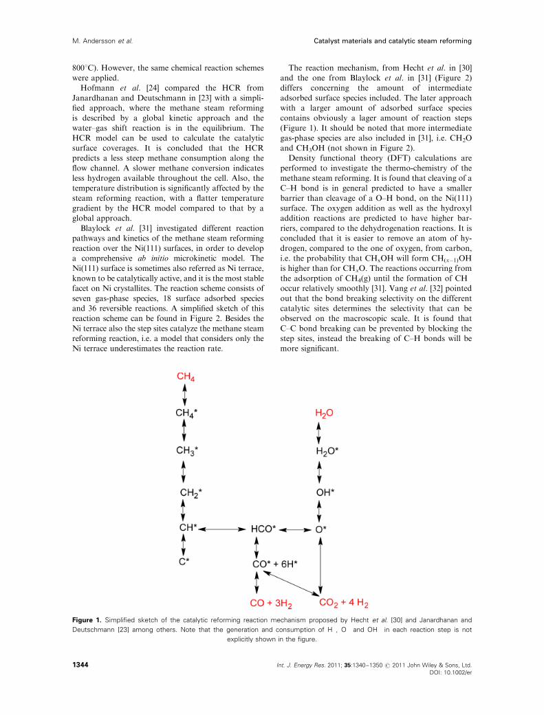
A multi-step heterogeneous reaction mechanism
(HCR) for Ni/YSZ catalysts has been developed by
Hecht et al. in [30]. This mechanism consists of 21
reversible reactions, 6 gas-phase species and 12 surface
adsorbed species. The mechanism is elementary in
nature and covers the global aspects of the steam re-
forming, the water–gas shift, the Bouduard reactions
and also the surface-carbon coverage. A simplified
sketch of this reaction mechanism can be seen in
Figure 1. Most of the expressions are expressed in the
Arrhenius rate form and depends on the surface cov-
erages. This model is validated by the experimental
results. The experiments (using a porous Ni-YSZ
anode) were designed to measure the extent of
reformation processes under the conditions well away
from equilibrium conditions. Pure steam reforming
and pure dry reforming with carbon dioxide as well as
a combination of these were included in the validation.
Note that this mechanism is not validated on the
conditions where coking and bulk-phase Ni oxidation
occur [30].
The HCR developed by Hecht et al. in [30] was
extended by Janardhanan and Deutschmann in [23]
to describe a larger temperature range between 220
and 17001C (compared to a constant temperature of
Catalyst materials and catalytic steam reforming M. Andersson et al.
Int. J. Energy Res. 2011; 35:1340–1350 r 2011 John Wiley & Sons, Ltd.
DOI: 10.1002/er
1343
8001C). However, the same chemical reaction schemes
were applied.
Hofmann et al. [24] compared the HCR from
Janardhanan and Deutschmann in [23] with a simpli-
fied approach, where the methane steam reforming
is described by a global kinetic approach and the
water–gas shift reaction is in the equilibrium. The
HCR model can be used to calculate the catalytic
surface coverages. It is concluded that the HCR
predicts a less steep methane consumption along the
flow channel. A slower methane conversion indicates
less hydrogen available throughout the cell. Also, the
temperature distribution is significantly affected by the
steam reforming reaction, with a flatter temperature
gradient by the HCR model compared to that by a
global approach.
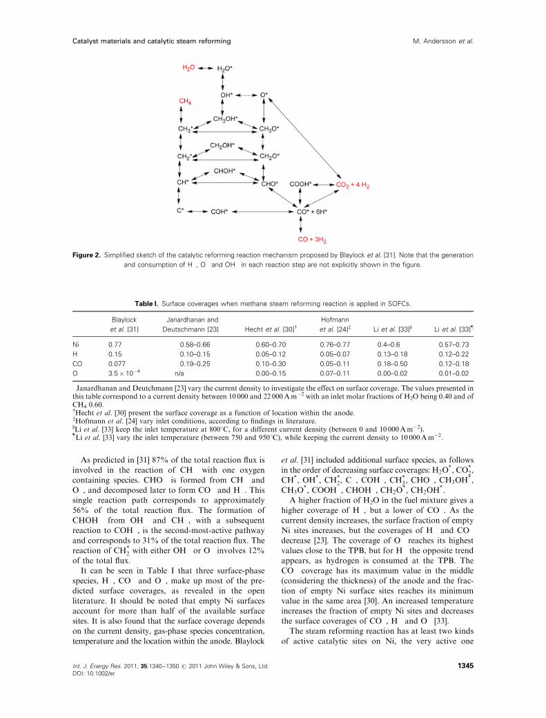
Blaylock et al. [31] investigated different reaction
pathways and kinetics of the methane steam reforming
reaction over the Ni(111) surfaces, in order to develop
a comprehensive ab initio microkinetic model. The
Ni(111) surface is sometimes also referred as Ni terrace,
known to be catalytically active, and it is the most stable
facet on Ni crystallites. The reaction scheme consists of
seven gas-phase species, 18 surface adsorbed species
and 36 reversible reactions. A simplified sketch of this
reaction scheme can be found in Figure 2. Besides the
Ni terrace also the step sites catalyze the methane steam
reforming reaction, i.e. a model that considers only the
Ni terrace underestimates the reaction rate.
The reaction mechanism, from Hecht et al. in [30]
and the one from Blaylock et al. in [31] (Figure 2)
differs concerning the amount of intermediate
adsorbed surface species included. The later approach
with a larger amount of adsorbed surface species
contains obviously a lager amount of reaction steps
(Figure 1). It should be noted that more intermediate
gas-phase species are also included in [31], i.e. CH2O
and CH3OH (not shown in Figure 2).
Density functional theory (DFT) calculations are
performed to investigate the thermo-chemistry of the
methane steam reforming. It is found that cleaving of a
C–H bond is in general predicted to have a smaller
barrier than cleavage of a O–H bond, on the Ni(111)
surface. The oxygen addition as well as the hydroxyl
addition reactions are predicted to have higher bar-
riers, compared to the dehydrogenation reactions. It is
concluded that it is easier to remove an atom of hy-
drogen, compared to the one of oxygen, from carbon,
i.e. the probability that CHxOH will form CHðx�1ÞOH
is higher than for CHxO. The reactions occurring from
the adsorption of CH4(g) until the formation of CH�
occur relatively smoothly [31]. Vang et al. [32] pointed
out that the bond breaking selectivity on the different
catalytic sites determines the selectivity that can be
observed on the macroscopic scale. It is found that
C–C bond breaking can be prevented by blocking the
step sites, instead the breaking of C–H bonds will be
more significant.
Figure 1. Simplified sketch of the catalytic reforming reaction mechanism proposed by Hecht et al. [30] and Janardhanan and
Deutschmann [23] among others. Note that the generation and consumption of H�, O� and OH� in each reaction step is not
explicitly shown in the figure.
Catalyst materials and catalytic steam reformingM. Andersson et al.
1344 Int. J. Energy Res. 2011; 35:1340–1350 r 2011 John Wiley & Sons, Ltd.
DOI: 10.1002/er
As predicted in [31] 87% of the total reaction flux is
involved in the reaction of CH� with one oxygen
containing species. CHO� is formed from CH� and
O�, and decomposed later to form CO� and H�. Thissingle reaction path corresponds to approximately
56% of the total reaction flux. The formation of
CHOH� from OH� and CH�, with a subsequent
reaction to COH�, is the second-most-active pathway
and corresponds to 31% of the total reaction flux. The
reaction of CH�2 with either OH� or O� involves 12%of the total flux.
It can be seen in Table I that three surface-phase
species, H�, CO� and O�, make up most of the pre-
dicted surface coverages, as revealed in the open
literature. It should be noted that empty Ni surfaces
account for more than half of the available surface
sites. It is also found that the surface coverage depends
on the current density, gas-phase species concentration,
temperature and the location within the anode. Blaylock
et al. [31] included additional surface species, as follows
in the order of decreasing surface coverages: H2O�, CO�2,
CH�, OH�, CH�2, C�, COH�, CH�3, CHO�, CH3OH�,
CH3O�, COOH�, CHOH�, CH2O
�, CH2OH�.
A higher fraction of H2O in the fuel mixture gives a
higher coverage of H�, but a lower of CO�. As the
current density increases, the surface fraction of empty
Ni sites increases, but the coverages of H� and CO�
decrease [23]. The coverage of O� reaches its highest
values close to the TPB, but for H� the opposite trendappears, as hydrogen is consumed at the TPB. The
CO� coverage has its maximum value in the middle
(considering the thickness) of the anode and the frac-
tion of empty Ni surface sites reaches its minimum
value in the same area [30]. An increased temperature
increases the fraction of empty Ni sites and decreases
the surface coverages of CO�, H� and O� [33].The steam reforming reaction has at least two kinds
of active catalytic sites on Ni, the very active one
Figure 2. Simplified sketch of the catalytic reforming reaction mechanism proposed by Blaylock et al. [31]. Note that the generation
and consumption of H�, O� and OH� in each reaction step are not explicitly shown in the figure.
Table I. Surface coverages when methane steam reforming reaction is applied in SOFCs.
Blaylock
et al. [31]
Janardhanan and
Deutschmann [23]� Hecht et al. [30]yHofmann
et al. [24]z Li et al. [33]y Li et al. [33]z
Ni 0.77 0.58–0.66 0.60–0.70 0.76–0.77 0.4–0.6 0.57–0.73
H� 0.15 0.10–0.15 0.05–0.12 0.05–0.07 0.13–0.18 0.12–0.22
CO� 0.077 0.19–0.25 0.10–0.30 0.05–0.11 0.18–0.50 0.12–0.18
O� 3.5� 10�4 n/a 0.00–0.15 0.07–0.11 0.00–0.02 0.01–0.02
�Janardhanan and Deutchmann [23] vary the current density to investigate the effect on surface coverage. The values presented inthis table correspond to a current density between 10 000 and 22 000Am�2 with an inlet molar fractions of H2O being 0.40 and ofCH4 0.60.yHecht et al. [30] present the surface coverage as a function of location within the anode.zHofmann et al. [24] vary inlet conditions, according to findings in literature.yLi et al. [33] keep the inlet temperature at 8001C, for a different current density (between 0 and 10 000Am�2).zLi et al. [33] vary the inlet temperature (between 750 and 9501C), while keeping the current density to 10 000Am�2.
Catalyst materials and catalytic steam reforming M. Andersson et al.
Int. J. Energy Res. 2011; 35:1340–1350 r 2011 John Wiley & Sons, Ltd.
DOI: 10.1002/er
1345

associated with the step and defect sites on the surface
and the less active one associated with the close-packed
facets. It is found that there are at least two different
reaction channels for the steam reforming of methane
on Ni, the one associated with steps with a low acti-
vation barrier and the one with the terraces with a
higher activation barrier. It is concluded that there are
many more active terrace sites compared to the active
step sites. The coke formation occurs at the step sites.
It is possible to add different additives that block dif-
ferent step sites and certainly decreases the probability
for the coke formation. An optimized catalyst will have
just enough additives that the coke formation is ef-
fectively blocked, while the fast channel reaction can
still proceed [34].
Metal particles grown at HT on coke or oxide sub-
strate have polyhedral shapes exhibiting (111), (100)
and (110) facets. Ni(111) is frequently included in the
kinetic and thermodynamic studies, but Ni(100) and
Ni(110) are less studied. Wang et al. [35] used a DFT
approach to investigate and clarify the thermo-
dynamics of CH4 dissociation on Ni-based catalysts:
Ni(111) has four possible surface sites: the top site
(tp), the bridge site (br), the hexagonal-closed-packed
site (hcp) and the face-centered cubic site (fcc). Stable
structures are found for CH�3(tp-a1, tp-a2, hcp-c and
fcc-d), CH�2(tp–a, hcp-c and fcc-d), CH� (hcp-c and fcc-
d), C� (hcp-c and fcc-d) and H� (tp-a, hcp-c and fcc-d).
On the basis of the binding energy it is found that CHx
and H prefer to chemisorb on the hcp and fcc [35].
Ni(100) has three possible surface sites: the tp, the br
and the hollow site (hl). Stable structures are found for
CH�3(tp-e1, tp-e2, br-f1 and br-f2), CH�2(tp–e1, tp-e2,
br-f and hl-g), CH� (hl-g), C� (hl-g) and H� (tp-e, br-fand hl-g). On the basis of the binding energy it is
concluded that CH3 prefers to chemisorb on the br,
while CH2, CH, C and H prefer to chemisorb on the hl.
It is further concluded that Ni(100) has a high re-
activity, but a low stability as the catalyst for CH4
steam reforming reaction [35].
Ni(110) has six possible surface sites: the top-up site
(tu), the short bridge site (sb), the top-down site (td),
the long-bridge site (lb), the hollow site formed by two
top-layers Ni and one sub-layer Ni (u2dl) and the
hollow site formed by one top-layer Ni and two
sub-layers Ni (uld2). Stable structures are found for
CH�3(tu-h1, tu-h2, sb-i1 and sb-i2), CH�2(tu–h, sb-I
and td-j), CH� (sp-I, usdl-l, lb-k and td-j), C� (tu-h,
sb-i, lb-k, td-j) and H� (tu-h, sb-I, u2dl-l and lb-k).
On the basis of the binding energy it is found that CH3
and CH2 prefer to chemisorb on the sb, while CH, C
and H prefer to chemisorb on the lb, td and u2dl,
respectively [35].
4.2. Microkinetic models
A great deal of information is available for Ni as the
reforming catalyst, because it has been commonly used
for catalysis in the chemical industry. For SOFC
anodes, the ceramic oxygen-ion conductor YSZ
itself also has catalytic activity for the partial oxida-
tion. Most reaction rates are represented in an
Arrhenius-type equation or as a sticking coefficient.
A kinetic model can be constructed by combining
thermochemical values for each species with calculated
activation energies and transition-state properties.
The forward rate coefficients are described either as a
surface reaction rate coefficient or an adsorption
reaction. The original kinetic data were often taken
from a variety of different catalysis studies, which
makes the mechanism not thermodynamically consis-
tent. Therefore, some of the original kinetic parameters
are often modified to ensure the overall consistency
concerning the enthalpy and the entropy. This
approach permits the computation of the reverse
reaction rate coefficients, which in turn is dependent
on the forward reaction rate coefficients [30]. Since
this mechanism is based on the elementary steps,
it, therefore, represents all the global processes in the
anode.
For the surface reactions and the desorption reac-
tions, often the Arrhenius form is applied for the re-
action rate constants, at least for small or moderate
variations of the temperature for the reactions [36].
The Arrhenius form is introduced in Equation (6) for
the global reaction kinetics and can be compared to the
following equations. The reaction rate constant of a
generalized modification of an Arrhenius-type equa-
tion including the surface-phase species coverages can
be expressed as [23]:
ki ¼ Ai � Tni � exp�Ei
R � T
� � YKg1Ks
k¼1
ymkik � exp�eki � ykR � T
� �
ð10Þ
where Ai is the pre-exponential factor, T the reaction
temperature, ni the temperature exponent fraction,
R the gas constant and Ei the activation energy for
the reaction i. To describe the coverage dependency,
mki and eki (coverage dependent activation energy)
are introduced for the parameters for species k and
reaction i.
The species molar production rate depends on the
surface-phase species concentration which is some-
times expressed as the coverage yk. The coverage is thefraction of the surface sites covered by the adsorbed
species k to the total active sites on the catalyst surface.
The relation between the surface coverage or the sur-
face concentration is expressed as [37]:
yk ¼ck � skGtot
ð11Þ
where yk is the surface coverage, sk the co-ordination
number (number of the sites required for a species of
adsorption), ck the concentration and Gtot the total
surface site density.
Catalyst materials and catalytic steam reformingM. Andersson et al.
1346 Int. J. Energy Res. 2011; 35:1340–1350 r 2011 John Wiley & Sons, Ltd.
DOI: 10.1002/er

The reaction rate constant for the surface reaction
can also be written as [31]:
ki ¼kb � Th
� ��
QTS � ðQ0slabÞRtot�1
QRtot
r¼1Qr
0BBB@
1CCCA � vN
0 Rtot�1sites
CRads�1T
� exp�Eb
R � T
� �ð12Þ
where kb is the Boltzmann constant, h the Plank con-
stant, Q the total partition function, Rtot the total
number of the reactants participating in the reaction,
Rads the total number of adsorbate reactants and Nsites
the standard-state number of the binding sites per
adsorbate.
Non-activated adsorption is calculated using the
kinetic theory of the gases assuming the sticking
coefficient to be equal to the fraction of vacant sites.
The forward reaction rate constant can be presented
for the non-activated adsorption as [31]:
ki ¼
ffiffiffiffiffiffiffiffiffiffiffiffiffiffiffiffiffikb � T
2 � p �M
rð13Þ
where M is the molecular mass of the gas-phase species
and kj the reaction rate constant.
Hecht et al. [30], Janharhanen and Deutschmann
[23] and Hofmann et al. [24] were, for the adsorption
reactions, applying an approach with a sticking coef-
ficient instead of the approach in Equation (10). The
forward reaction rate constants including the sticking
coefficient for the non-activated adsorption reaction
can be expressed as [24]:
ki ¼gj
ðGtotÞm �
ffiffiffiffiffiffiffiffiffiffiffiffiffiffiffiffiffiR � T
2 � p �M
rð14Þ
where gj is the sticking coefficient.
For the activated adsorption and for the surface
reactions, the transition-state theory can be applied to
obtain the reaction rate coefficients for the forward
reaction. The forward reaction rate constant for the
activated molecular adsorption is written as [31]:
ki ¼kb � Th
� ��
QTS
Qgas �Qslab
� ��
R � Tp0
� �� Gtot
� exp�Eb
R � T
� �ð15Þ
where Eb is the classical electronic energy barrier of
adsorption and p0 the standard pressure.
The construction of a kinetic model for the relation-
ship between the standard free energy change of an
elementary reaction step and the equilibrium constant
needs to be formed. When the equilibrium constant and
the forward reaction rate constant are known, the re-
verse reaction rate constant can be expressed as [38]:
k�1;i ¼ki
Ke;ið16Þ
where Ke;j is the equilibrium constant. The equilibrium
constant of a reaction can be defined as [36]:
Ke;j ¼ exp �DGi
R � T
� �¼ exp �
DHi � T � DSi
R � T
� �ð17Þ
where DG is a change in Gibbs energy due to the che-
mical reaction, DH the enthalpy change and DS the
entropy change of the reaction. It should be noted that
the principle of reversibility should be used with some
caution. The mechanism for the reaction can be
reversible for a given set of concentrations, temperature
and pressure, but may not be valid for different sets of
reaction conditions. The reaction may proceed through
the same steps in the forward and the backward reac-
tions but the rate of the individual steps may differ by
several orders of magnitude [36].
5. CONCLUSIONS
Understanding of the methane steam reforming reactions
and catalyst materials structure is expected to be of
significant importance for the further SOFC develop-
ment. The reforming reaction rates are either described
by a global kinetics approach or by a more detailed
approach applying elementary surface reaction kinetics.
It is concluded that the reaction order varies significantly
in the global models. The reaction order for water can be
negative or positive. It is found that the water–gas shift
reaction is usually assumed to be in equilibrium.
Different mechanisms considering elementary surface
kinetics have been developed. However, there is a
disagreement considering the involved reaction path-
ways, the intermediate species and rate-limiting steps.
The CO� formation as well as the methane adsorption
have been suggested as the rate limiting steps. It should
be noted that empty nickel occupies normally more than
half of the available surfaces, as identified in the open
literature. Three surface species (H�, CO� and O�) arethe dominant components in terms of the surface
coverage. The nickel particle surfaces contain variable
structures for the catalytic reactions. Typically, only parts
of them are chemically available. This might be the
reason why lower reaction rates were predicted by the
detailed models, compared to those by the global models.
NOMENCLATURE
ck 5 concentration (molm�2)
E 5 activation energy (kJmol�1)
Eb 5 classical electronic energy barrier of
adsorption (Jmol�1)
DG 5Gibbs energy (Jmol�1)
h 5Plank constant (J s)
DH 5 enthalpy change of reaction (Jmol�1)
k 5 reaction rate constant
(molm�3 Pa�2 s�1)
Catalyst materials and catalytic steam reforming M. Andersson et al.
Int. J. Energy Res. 2011; 35:1340–1350 r 2011 John Wiley & Sons, Ltd.
DOI: 10.1002/er
1347

kb 5Boltzmann constant (1.38� 10�23JK�1)
Ke 5 equilibrium constant, unit depends
on the actual reaction
M 5molecular mass (kgmol�1)
Nsites 5 standard-state number of binding
sites per adsorbate.
p 5 pressure (Pa, bar)
Q 5 total partition function
r 5 chemical reaction rate (molm�3 s�1,
molm�2 s�1)
R 5 gas constant (8.314 Jmol�1K�1)
Rads 5 total number of adsorbate reactants
Rtot 5 total number of reactants participat-
ing in the reaction
SA 5 surface area ratio (m2m�3)
DS 5 entropy change of reaction
(Jmol�1K�1)
T 5 temperature (K)
Greek symbols
sk 5 co-ordination number (molm�2)
yk 5 surface coverage (�)gj 5 sticking coefficient (�)Gtot 5 surface site density (molm�2)
Abbreviations
DFT 5 density functional theory
DIR 5 direct internal reforming
ER 5 external reforming
FC 5 fuel cell
g 5 gas phase
HCR 5 heterogeneous reaction mechanism
HT 5 high temperature
IIR 5 indirect internal reforming
IR 5 internal reforming
IT 5 intermediate temperature
LT 5 low temperature
PEMFC 5 proton exchange membrane fuel cell
SC 5 steam-to-carbon ratio
SOFC 5 solid oxide fuel cell
TPB 5 three-phase boundary
YSZ 5 yttria-stabilized zirconia
Chemical
* 5 surface species connected to the
catalytic (Ni) active area
Ag 5 silver
Au 5 gold
CeO2 5 ceria
CH4 5methane
CO 5 carbon monoxide
Co 5 cobalt
CO2 5 carbon dioxide
Cu 5 copper
H2 5 hydrogen
H2O 5water
Ni 5 nickel
O2 5 oxygen
Pd 5 palladium
Pt 5 platinum
Ru 5 ruthenium
W 5 tungsten
Facets on Ni
br 5 bridge site, on Ni(111) and Ni(100)
fcc 5 face-centered cubic site, on Ni(111)
hcp 5 hexagonal-closed-packed site, on
Ni(111)
hl 5 hollow site, on Ni(111)
lb 5 long-bridge site, on Ni(110)
sb 5 short bridge site, on Ni(110)
td 5 top-down site, on Ni(110)
tp 5 top site, on Ni(111) and Ni(100)
tu 5 top-up site, on Ni(110)
u2dl 5 hollow site formed by two top-layers
Ni and one sub-layer Ni, on Ni(110)
uld2 5 hollow site formed by one lop-layer
Ni and two sub-layers Ni, on Ni(110)
ACKNOWLEDGEMENTS
The financial support from the Swedish ResearchCouncil (VR, 621-2010-4581) and the EuropeanResearch Council (ERC, 226238-MMFCs) is gratefullyacknowledged.
REFERENCES
1. Andersson M, Yuan J, Sunden B. Review on
modeling development for multiscale chemical reac-
tions coupled transport phenomena in solid oxide
fuel cells. Applied Energy 2010; 87:1461–1476. DOI:
10.1016/j.apenergy.2009.11.013.
2. Saxe M. Bringing fuel cells to reality and reality to
fuel cells, Doctoral Thesis, Department of Chemical
Sciences and Engineering, KTH-Royal Institute of
Technology, Sweden, 2008.
3. Kemm M. Dynamic solid oxide fuel cell modelling
for non-steady state simulation of system applica-
tions, Doctoral Thesis, Department of Energy
Sciences, Lund University, Sweden, 2006.
4. Kakac S, Pramuanjaroenkij A, Zhou X. A review of
numerical modeling of solid oxide fuel cells. Inter-
national Journal of Hydrogen Energy 2007; 32:
761–786.
5. Zhu H, Kee R, Janardhanan V, Deutschmann O,
Goodwin D. Modeling elementary heterogeneous
chemistry and electrochemistry in solid-oxide fuel
cells. Journal of Electrochemical Society 2005; 152:
A2427–A2440.
Catalyst materials and catalytic steam reformingM. Andersson et al.
1348 Int. J. Energy Res. 2011; 35:1340–1350 r 2011 John Wiley & Sons, Ltd.
DOI: 10.1002/er

6. Ni M, Leung MKH, Leung DYC. Ammonia-fed
solid oxide fuel cells for power generation—a
review. International Journal of Energy Research
2009; 33:943–959.
7. Gooenough JB, Huang Y. Alternative anode
materials for solid oxide fuel cells. Journal of Power
Sources 2007; 173:1–10.
8. Boder M, Dittmeyer R. Catalytic modification of
conventional SOFC anodes with a view to reducing
their activity for direct internal reforming of natural
gas. Journal of Power Sources 2006; 155:13–22.
9. Dokmaingam P, Assabumrungrat S, Soottitantawat A,
Laosiripojana N. Modelling of tubular-designed
solid oxide fuel cell with indirect internal reforming
operation fed by different primary fuels. Journal of
Power Sources 2010; 195:69–78.
10. Clarke S, Dicks A, Pointon K, Smith T, Swann A.
Catalytic aspects of the steam reforming of hydro-
carbons in internal reforming fuel cells. Catalysis
Today 1997; 38:411–423.
11. Gross MD, Vohs JM, Gorte RJ. A study of thermal
stability and methane tolerance of Cu-based SOFC
anodes with electrodeposited Co. Electrochimica
Acta 2007; 52:1951–1957.
12. Sadykov VA, Mezentseva NV, Bunina RV,
Alikina GM, Lukashevich AI, Kharlamova TS,
Rogov VA, Zaikovskii VI, Ishchenko AV,
Krieger TA, Bobrenok OF, Smirnova A, Irvine J,
Vasylyev OD. Effect of complex oxide promoters
and Pd on activity and stability of Ni/YSZ (ScSZ)
cermets as anode materials for IT SOFC. Catalysis
Today 2008; 131:226–237.
13. Costa-Nunes O, Gorte RJ, Vohs JM. Comparison
of the performance of Cu-CeO2-YSZ and Ni-YSZ
composite SOFC anodes with H2, CO, and syngas.
Journal of Power Sources 2005; 141:241–249.
14. Gorte RJ. Ceria in catalysis: from automotive
applications to the water-gas shift reaction. AIChE
Journal 2010; 56:1126–1135.
15. Aguiar P, Adjiman CS, Brandon NP. Anode-
supported intermediate-temperature direct internal
reforming solid oxide fuel Cell II. Model-based
dynamic performance and control. Journal of Power
Sources 2005; 147:136–147.
16. Nagel F, Schildhauer T, Biollaz S, Stucki S. Charge,
mass and heat transfer interactions in solid oxide
fuel cells operated with different fuel gases—a
sensitivity analysis. Journal of Power Sources 2008;
184:129–142.
17. Danilov VA, Tade MO. A CFD-based model of a
planar SOFC for anode flow field design. Interna-
tional Journal of Hydrogen Energy 2009; 34:
8998–9006.
18. Klein J-M, Bultel Y, Georges S, Pons M. Modeling
of a SOFC fuelled by methane: from direct internal
reforming of gradual internal reforming. Chemical
Engineering Science 2007; 62:1636–1649.
19. Marrero-Lopez D, Ruiz-Morales JC, Pena-
Martınez J, Canales-Vazquez J, Nunez P. Prepara-
tion of thin layer material with macroporous
microstructure for SOFC applications. Journal of
Solid State Chemistry 2008; 181:685–692.
20. Drescher I, Kinetik der Methane-Dampf-Re-
formierung (in German), kinetics of the methane
steam reforming (title translated to English), Doctoral
Thesis, Research Institute Julich, Germany, 1999.
21. Yuan J, Huang Y, Sunden B, Wang WG. Analysis
of parameter effects on chemical reaction coupled
transport phenomena in SOFC anodes. Heat and
Mass Transfer 2009; 45:471–484.
22. Haberman BA, Young JB. Three-dimensional si-
mulation of chemically reacting gas flows in the
porous support structure of an integrated-planar
solid oxide fuel cell. International Journal of Heat
and Mass Transfer 2004; 47:3617–3629.
23. Janardhanan VM, Deutschmann O. CFD analysis
of a solid oxide fuel cell with internal reforming:
coupled interactions of transport, heterogeneous
catalysis and electrochemical processes. Journal of
Power Sources 2006; 162:1192–1202.
24. Hofmann P, Panopoulos KD, Fryda LE,
Kakaras E. Comparison between two methane
reforming models applied to a quasi-two-dimen-
sional planar solid oxide fuel cell model. Energy
2008; 34:2151–2157.
25. Wang L, Zhang H, Weng S. Modeling and
simulation of solid oxide fuel cell based on the
volume–resistance characteristic modeling techni-
que. Journal of Power Sources 2008; 177:579–589.
26. Bessler WG, Gewies S, Vogler M. A new frame-
work for physically based modeling of solid
oxide fuel cells. Electrochimica Acta 2007; 53:
1782–1800.
27. King D, Strohm J, Wang X, Roh H-S, Wang C,
Chin Y-H, Wang Y, Lin Y, Rozmiarek R, Singh P.
Effect on nickel microstructure on methane steam
reforming activity of Ni-YSZ cermet anode catalyst.
Journal of Catalysis 2008; 258:356–365.
28. Jones G, Jakobsen JG, Shim SS, Kleis J,
Andersson MP, Rossmeisl J, Abild-Pedersen F,
Bligaard T, Helveg S, Hinnemann B, Rostrup-
Nielsen JR, Chorkendorff I, Sehested J, Jens K,
Norskov JK. First principles calculations and
experimental insight into methane steam reforming
over transition metal catalysts. Journal of Catalysis
2008; 259:147–160.
Catalyst materials and catalytic steam reforming M. Andersson et al.
Int. J. Energy Res. 2011; 35:1340–1350 r 2011 John Wiley & Sons, Ltd.
DOI: 10.1002/er
1349

29. Molenda J, Swierczek K, Zajac W. Functional
materials for IT-SOFC. Journal of Power Sources
2007; 173:657–670.
30. Hecht E, Gupta G, Zhu H, Dean A, Kee R,
Maier L, Deutschmann O. Methane reforming
kinetics within a Ni-YSZ SOFC anode support.
Applied Catalysis A: General 2005; 295:40–51.
31. Blaylock D, Ogura WT, Green WH, Beran GJO.
Computational investigation of thermochemistry
and kinetics of steam methane reforming on
Ni(111) under realistic conditions. Journal of
Physical Chemistry C 2009; 113:4898–4908.
32. Vang RT, Honkala K, Dahl S, Vestergaard EK,
Schnadt J, Lægsgaard E, Clausen BS, Nørskov JK,
Besenbacher F. Controlling the catalytic bond-
breaking selectivity of Ni surfaces by step blocking.
Nature Materials 2005; 4:160–162.
33. Li C, Shi Y, Cai N. Elementary reaction kinetic
model of an anode-supported solid oxide fuel cell
fueled with syngas. Journal of Power Sources 2010;
195:2266–2282.
34. Bengaard HS, Norskov JK, Sehested J, Clausen BS,
Nielsen LP, Molenbroek AM, Rostrup-Nielsen JR.
Steam reforming and graphite formation on Ni
catalysts. Journal of Catalysis 2002; 209:365–384.
35. Wang S-G, Cao D-B, Li Y-W, Wang J, Jiao H.
CH4 dissociation on Ni surfaces: density functional
theory study. Surface Science 2006; 600:3226–3234.
36. Stolze P. Microkinetic simulation of catalytic reactions.
Progress in Surface Science 2000; 65:65–150.
37. Janardhanan VM, Heuveline V, Deutschmann O.
Performance analysis of a SOFC under direct
internal reforming conditions. Journal of Power
Sources 2007; 172:296–307.
38. Yang Y, Du X, Yang L, Huang Y, Xian H.
Investigation of methane steam reforming in planar
porous support of solid oxide fuel cell. Applied
Thermal Engineering 2009; 29:1106–1113.
Catalyst materials and catalytic steam reformingM. Andersson et al.
1350 Int. J. Energy Res. 2011; 35:1340–1350 r 2011 John Wiley & Sons, Ltd.
DOI: 10.1002/er


![SOFCOM Meeting M24 - areeweb.polito.it · Cleaning Unit Reforming Unit SOFC Stack Unit Oxy-combustor CO2 separation Unit ... Total flow rate [NLPM] 57 30 2 Available temperature [°C]](https://static.fdocuments.us/doc/165x107/5abfacb67f8b9a8e3f8e94bf/sofcom-meeting-m24-unit-reforming-unit-sofc-stack-unit-oxy-combustor-co2-separation.jpg)