Review LensesLens Maker Formula · 2005-03-29 · Lens Maker Formula!Ifth frontsurface ofthe...
5
March 29, 2005 Physics for Scientists&Engineers 2 1 Physics for Scientists & Physics for Scientists & Engineers Engineers 2 Spring Semester 2005 Lecture 38 March 29, 2005 Physics for Scientists&Engineers 2 2 Review Review ! The index of refraction of an optical material, n, is given by • c is the speed of light in a vacuum • v is the speed of light in the optical material • n ! 1, n vacuum =1 • We will use n air = 1 ! The Law of Refraction or Snell’s Law can be expressed as n = c v n 1 sin! 1 = n 2 sin! 2 March 29, 2005 Physics for Scientists&Engineers 2 3 Lenses Lenses ! When light is refracted crossing a curved boundary between two different media, the light rays follow the law of refraction at each point on the boundary ! The angle at which the light rays cross the boundary is different along the boundary, so the refracted angle is different at different points along the boundary ! A curved boundary between two optically transparent media is called a lens ! Light rays that are initially parallel before they strike the boundary are refracted in different directions depending on the part of the lens they strike ! Depending of the shape of the lens, the light rays can be focused or caused to diverge March 29, 2005 Physics for Scientists&Engineers 2 4 Lens Maker Formula Lens Maker Formula ! If the front surface of the lens is part of the surface of a sphere with radius R 1 and the back surface of the lens is part of the surface of a sphere with radius R 2 , then we can calculate the focal length f of the lens using the lens-makers formula ! Note that in this equation R 2 is negative because it has the opposite curvature from the front surface ! If we have a lens with the same radii on the front and back of the lens so that R 1 = R 2 = R, we get 1 f = n ! 1 ( ) 1 R 1 ! 1 R 2 " # $ % & ’ 1 f = 2(n ! 1) R
Transcript of Review LensesLens Maker Formula · 2005-03-29 · Lens Maker Formula!Ifth frontsurface ofthe...
March 29, 2005 Physics for Scientists&Engineers 2 1
Physics for Scientists &Physics for Scientists &
EngineersEngineers 22
Spring Semester 2005
Lecture 38
March 29, 2005 Physics for Scientists&Engineers 2 2
ReviewReview
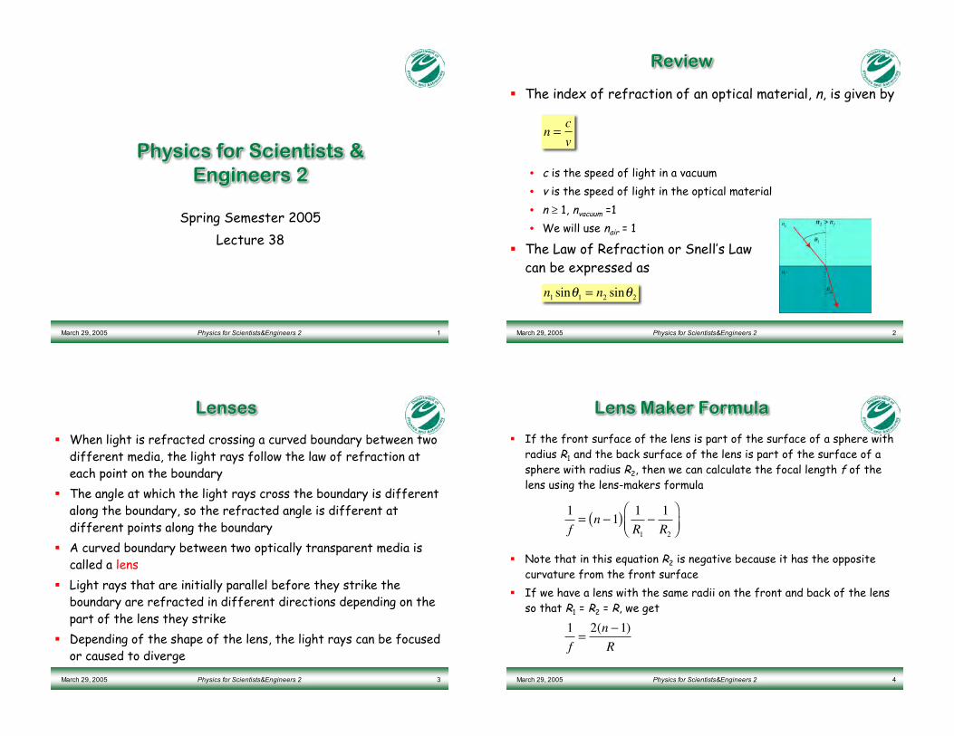
! The index of refraction of an optical material, n, is given by
• c is the speed of light in a vacuum
• v is the speed of light in the optical material
• n ! 1, nvacuum =1
• We will use nair = 1
! The Law of Refraction or Snell’s Lawcan be expressed as
n =c
v
n1sin!
1= n
2sin!
2
March 29, 2005 Physics for Scientists&Engineers 2 3
LensesLenses
! When light is refracted crossing a curved boundary between twodifferent media, the light rays follow the law of refraction ateach point on the boundary
! The angle at which the light rays cross the boundary is differentalong the boundary, so the refracted angle is different atdifferent points along the boundary
! A curved boundary between two optically transparent media iscalled a lens
! Light rays that are initially parallel before they strike theboundary are refracted in different directions depending on thepart of the lens they strike
! Depending of the shape of the lens, the light rays can be focusedor caused to diverge
March 29, 2005 Physics for Scientists&Engineers 2 4
Lens Maker FormulaLens Maker Formula
! If the front surface of the lens is part of the surface of a sphere withradius R1 and the back surface of the lens is part of the surface of asphere with radius R2, then we can calculate the focal length f of thelens using the lens-makers formula
! Note that in this equation R2 is negative because it has the oppositecurvature from the front surface
! If we have a lens with the same radii on the front and back of the lensso that R1 = R2 = R, we get
1
f= n !1( )
1
R1
!1
R2
"
#$%
&'
1
f=2(n !1)
R
March 29, 2005 Physics for Scientists&Engineers 2 5
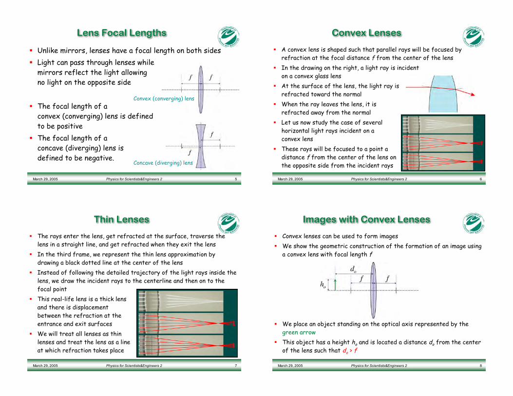
Lens Focal LengthsLens Focal Lengths
! Unlike mirrors, lenses have a focal length on both sides
! Light can pass through lenses whilemirrors reflect the light allowingno light on the opposite side
! The focal length of aconvex (converging) lens is definedto be positive
! The focal length of aconcave (diverging) lens isdefined to be negative.
Convex (converging) lens
Concave (diverging) lens
March 29, 2005 Physics for Scientists&Engineers 2 6
Convex LensesConvex Lenses
! A convex lens is shaped such that parallel rays will be focused byrefraction at the focal distance f from the center of the lens
! In the drawing on the right, a light ray is incidenton a convex glass lens
! At the surface of the lens, the light ray isrefracted toward the normal
! When the ray leaves the lens, it isrefracted away from the normal
! Let us now study the case of severalhorizontal light rays incident on aconvex lens
! These rays will be focused to a point adistance f from the center of the lens onthe opposite side from the incident rays
March 29, 2005 Physics for Scientists&Engineers 2 7
Thin LensesThin Lenses
! The rays enter the lens, get refracted at the surface, traverse thelens in a straight line, and get refracted when they exit the lens
! In the third frame, we represent the thin lens approximation bydrawing a black dotted line at the center of the lens
! Instead of following the detailed trajectory of the light rays inside thelens, we draw the incident rays to the centerline and then on to thefocal point
! This real-life lens is a thick lensand there is displacementbetween the refraction at theentrance and exit surfaces
! We will treat all lenses as thinlenses and treat the lens as a lineat which refraction takes place
March 29, 2005 Physics for Scientists&Engineers 2 8
Images with Convex LensesImages with Convex Lenses
! Convex lenses can be used to form images
! We show the geometric construction of the formation of an image usinga convex lens with focal length f
! We place an object standing on the optical axis represented by thegreen arrow
! This object has a height ho and is located a distance do from the centerof the lens such that do > f
March 29, 2005 Physics for Scientists&Engineers 2 9
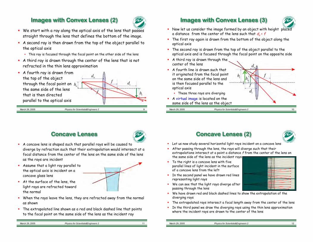
Images with Convex Lenses (2)Images with Convex Lenses (2)
! We start with a ray along the optical axis of the lens that passesstraight through the lens that defines the bottom of the image.
! A second ray is then drawn from the top of the object parallel tothe optical axis
• This ray is focused through the focal point on the other side of the lens
! A third ray is drawn through the center of the lens that is notrefracted in the thin lens approximation
! A fourth ray is drawn fromthe top of the objectthrough the focal point onthe same side of the lensthat is then directedparallel to the optical axis
March 29, 2005 Physics for Scientists&Engineers 2 10
Images with Convex Lenses (3)Images with Convex Lenses (3)
! Now let us consider the image formed by an object with height placeda distance from the center of the lens such that do < f
! The first ray again is drawn from the bottom of the object along theoptical axis
! The second ray is drawn from the top of the object parallel to theoptical axis and is focused through the focal point on the opposite side
! A third ray is drawn through thecenter of the lens
! A fourth line is drawn such thatit originated from the focal pointon the same side of the lens andis then focused parallel to theoptical axis• These three rays are diverging
! A virtual image is located on thesame side of the lens as the object
March 29, 2005 Physics for Scientists&Engineers 2 11
Concave LensesConcave Lenses
! A concave lens is shaped such that parallel rays will be caused todiverge by refraction such that their extrapolation would intersect at afocal distance from the center of the lens on the same side of the lensas the rays are incident
! Assume that a light ray parallel tothe optical axis is incident on aconcave glass lens
! At the surface of the lens, thelight rays are refracted towardthe normal
! When the rays leave the lens, they are refracted away from the normalas shown
! The extrapolated line shown as a red and black dashed line that pointsto the focal point on the same side of the lens as the incident ray
March 29, 2005 Physics for Scientists&Engineers 2 12
Concave Lenses (2)Concave Lenses (2)
! Let us now study several horizontal light rays incident on a concave lens
! After passing through the lens, the rays will diverge such that theirextrapolations intersect at a point a distance f from the center of the lens onthe same side of the lens as the incident rays
! To the right is a concave lens with fiveparallel lines of light incident in the surfaceof a concave lens from the left
! In the second panel we have drawn red linesrepresenting light rays
! We can see that the light rays diverge afterpassing through the lens
! We have drawn red and black dashed lines to show the extrapolation of thediverging rays
! The extrapolated rays intersect a focal length away from the center of the lens
! In the third panel we draw the diverging rays using the thin lens approximationwhere the incident rays are drawn to the center of the lens
March 29, 2005 Physics for Scientists&Engineers 2 13
Images formed with Concave LensesImages formed with Concave Lenses
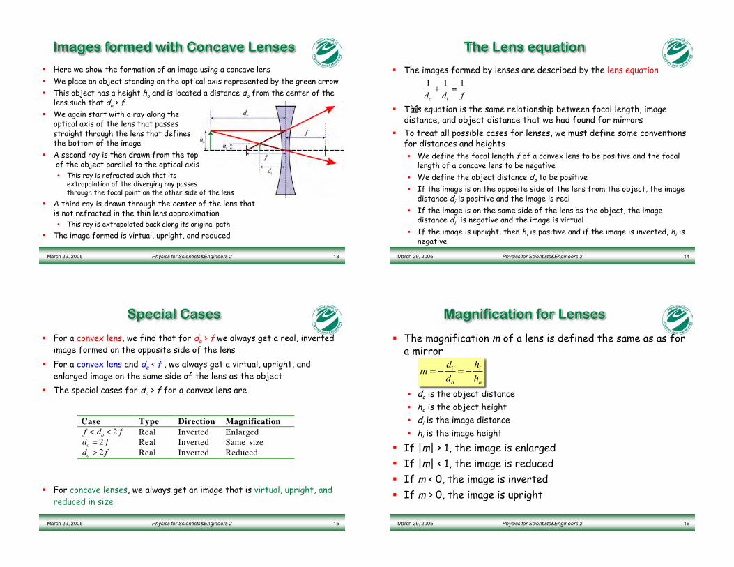
! Here we show the formation of an image using a concave lens
! We place an object standing on the optical axis represented by the green arrow
! This object has a height ho and is located a distance do from the center of thelens such that do > f
! We again start with a ray along theoptical axis of the lens that passesstraight through the lens that definesthe bottom of the image
! A second ray is then drawn from the top of the object parallel to the optical axis• This ray is refracted such that its
extrapolation of the diverging ray passesthrough the focal point on the other side of the lens
! A third ray is drawn through the center of the lens thatis not refracted in the thin lens approximation• This ray is extrapolated back along its original path
! The image formed is virtual, upright, and reduced
March 29, 2005 Physics for Scientists&Engineers 2 14
TheThe Lens equationLens equation
! The images formed by lenses are described by the lens equation
! This equation is the same relationship between focal length, imagedistance, and object distance that we had found for mirrors
! To treat all possible cases for lenses, we must define some conventionsfor distances and heights• We define the focal length f of a convex lens to be positive and the focal
length of a concave lens to be negative
• We define the object distance do to be positive
• If the image is on the opposite side of the lens from the object, the imagedistance di is positive and the image is real
• If the image is on the same side of the lens as the object, the imagedistance di is negative and the image is virtual
• If the image is upright, then hi is positive and if the image is inverted, hi isnegative
1
do+1
di=1
f
March 29, 2005 Physics for Scientists&Engineers 2 15
Special CasesSpecial Cases
! For a convex lens, we find that for do > f we always get a real, invertedimage formed on the opposite side of the lens
! For a convex lens and do < f , we always get a virtual, upright, andenlarged image on the same side of the lens as the object
! The special cases for do > f for a convex lens are
! For concave lenses, we always get an image that is virtual, upright, andreduced in size
Case Type Direction Magnification
f < do < 2 f Real Inverted Enlarged
do = 2 f Real Inverted Same size
do > 2 f Real Inverted Reduced
March 29, 2005 Physics for Scientists&Engineers 2 16
Magnification for LensesMagnification for Lenses
! The magnification m of a lens is defined the same as as fora mirror
• do is the object distance
• ho is the object height
• di is the image distance
• hi is the image height
! If |m| > 1, the image is enlarged
! If |m| < 1, the image is reduced
! If m < 0, the image is inverted
! If m > 0, the image is upright
m = !di
do
= !hi
ho
March 29, 2005 Physics for Scientists&Engineers 2 17
Power of LensesPower of Lenses
! The power of a lens is often quoted rather than its folcalength
! The power of a lens, D (diopters), is given by the equation
! For example, common reading glasses have a power ofD = 1.5 diopters
! The focal length of these glasses is
D =1 m
f
f =1 m
1.5 diopters= 0.67 m
March 29, 2005 Physics for Scientists&Engineers 2 18
Example: Image formed byExample: Image formed by Convex LensConvex Lens
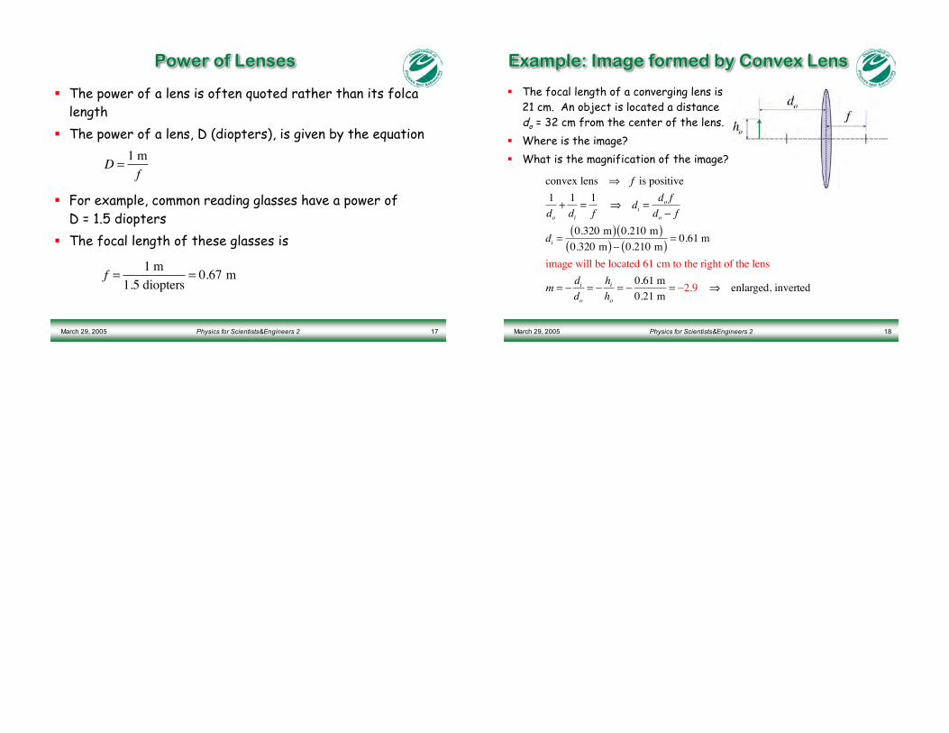
! The focal length of a converging lens is21 cm. An object is located a distancedo = 32 cm from the center of the lens.
! Where is the image?
! What is the magnification of the image?
convex lens ! f is positive
1
do+
1
di=
1
f ! di =
do f
do " f
di =0.320 m( ) 0.210 m( )
0.320 m( )" 0.210 m( )= 0.61 m
image will be located 61 cm to the right of the lens
m = "di
do= "
hi
ho= "
0.61 m
0.21 m= "2.9 ! enlarged, inverted