
Review, Classification and Comparison
24
energies Review Architectures of Planetary Hybrid Powertrain System: Review, Classification and Comparison Lihua Wang 1 , Yahui Cui 1 , Fengqi Zhang 1,2, * and Guanglei Li 1 1 School of Mechanical and Precision Instrument Engineering, Xi’an University of Technology, Xi’an 710048, China; [email protected] (L.W.); [email protected] (Y.C.); [email protected] (G.L.) 2 Key laboratory of Shaanxi Province for Development and Application of New Transportation, Chang ’an University, Xi’an 710064, China * Correspondence: [email protected] Received: 29 November 2019; Accepted: 8 January 2020; Published: 9 January 2020 Abstract: Increasing environmental issues and energy crises led to rapid developments of hybrid electric vehicles, especially the planetary hybrid powertrain system (PHPS). This paper presents a comprehensive review of the PHPS, focusing primarily on contributions in the aspect of configuration, classification and comparison. In this work, a new classification method for PHPS architectures is proposed according to the number of electric motors (EMs). In addition, two kinds of PHPS, in the new classification framework, are extensively emphasized in terms of its architectures, advantages and disadvantages. Furthermore, the port diagrams of representative architectures are presented to provide an intuitive method for power flow representation. Finally, a conclusion is made to provide an insight for developing PHPS as well. Keywords: hybrid electric vehicle; planetary hybrid powertrain system; configuration; classification; comparison 1. Introduction During the last twenty years, the number of the passenger cars worldwide has inexorably increased [1]. As a result, traffic-related energy and environmental problems have become serious [2–6]. This has pushed the governments, automotive companies and research institutes worldwide to seek economical viable and environmentally-friendly personal transportation solutions. The policymakers have made a series of vehicle emission regulations to reduce carbon emission stemming from transportation sources [7–10]. It is urgent to develop alternative fuels and energy-save technology [11–15]. Thus, the automotive makers and researchers have made great effort to explore efficient and sustainable solutions, most of which are focused on vehicle hybridization/electrification [16–22]. Hybrid electric vehicles (HEVs) have been widely considered as one of the most promising solutions to achieve superior mileage, lower fuel consumption and less tailpipe emission compared to conventional internal combustion engine based vehicles [16,23–25]. Generally, the HEV is composed of an internal combustion engine (ICE) (gasoline or diesel fueled) with one or more electric motors (EMs). Traditionally, based on the combinations of connections among components of the powertrain system, HEVs can be classified into three basic drivetrain architectures: series, parallel and power-split (also called series-parallel) [21,26–29]. A schematic representation of these three architectures is given in Figure 1. Nevertheless, it is critical to combine multi-powertrain transfer with different operation modes via power coupling device. Specifically, the power coupling of series HEVs is achieved by electro-electric coupling device only with electrical energy transfer in the drive system, while electromechanical Energies 2020, 13, 329; doi:10.3390/en13020329 www.mdpi.com/journal/energies
Transcript of Review, Classification and Comparison

energies
Review
Architectures of Planetary Hybrid Powertrain System:Review, Classification and Comparison
Lihua Wang 1, Yahui Cui 1, Fengqi Zhang 1,2,* and Guanglei Li 1
1 School of Mechanical and Precision Instrument Engineering, Xi’an University of Technology,Xi’an 710048, China; [email protected] (L.W.); [email protected] (Y.C.);[email protected] (G.L.)
2 Key laboratory of Shaanxi Province for Development and Application of New Transportation, Chang ’anUniversity, Xi’an 710064, China
* Correspondence: [email protected]
Received: 29 November 2019; Accepted: 8 January 2020; Published: 9 January 2020�����������������
Abstract: Increasing environmental issues and energy crises led to rapid developments of hybridelectric vehicles, especially the planetary hybrid powertrain system (PHPS). This paper presents acomprehensive review of the PHPS, focusing primarily on contributions in the aspect of configuration,classification and comparison. In this work, a new classification method for PHPS architectures isproposed according to the number of electric motors (EMs). In addition, two kinds of PHPS, in thenew classification framework, are extensively emphasized in terms of its architectures, advantagesand disadvantages. Furthermore, the port diagrams of representative architectures are presented toprovide an intuitive method for power flow representation. Finally, a conclusion is made to providean insight for developing PHPS as well.
Keywords: hybrid electric vehicle; planetary hybrid powertrain system; configuration;classification; comparison
1. Introduction
During the last twenty years, the number of the passenger cars worldwide has inexorablyincreased [1]. As a result, traffic-related energy and environmental problems have becomeserious [2–6]. This has pushed the governments, automotive companies and research institutesworldwide to seek economical viable and environmentally-friendly personal transportation solutions.The policymakers have made a series of vehicle emission regulations to reduce carbon emissionstemming from transportation sources [7–10]. It is urgent to develop alternative fuels andenergy-save technology [11–15]. Thus, the automotive makers and researchers have made greateffort to explore efficient and sustainable solutions, most of which are focused on vehiclehybridization/electrification [16–22].
Hybrid electric vehicles (HEVs) have been widely considered as one of the most promisingsolutions to achieve superior mileage, lower fuel consumption and less tailpipe emission compared toconventional internal combustion engine based vehicles [16,23–25]. Generally, the HEV is composed ofan internal combustion engine (ICE) (gasoline or diesel fueled) with one or more electric motors (EMs).Traditionally, based on the combinations of connections among components of the powertrain system,HEVs can be classified into three basic drivetrain architectures: series, parallel and power-split (alsocalled series-parallel) [21,26–29]. A schematic representation of these three architectures is given inFigure 1. Nevertheless, it is critical to combine multi-powertrain transfer with different operation modesvia power coupling device. Specifically, the power coupling of series HEVs is achieved by electro-electriccoupling device only with electrical energy transfer in the drive system, while electromechanical
Energies 2020, 13, 329; doi:10.3390/en13020329 www.mdpi.com/journal/energies

Energies 2020, 13, 329 2 of 24
coupling device are employed for parallel and power-split HEVs to combine multi-power sources,either propelling the vehicle together or independently. Various electromechanical coupling devicesfor a parallel or power-split HEV will be discussed in Section 2. In addition, the power-split HEVs canbe further divided into sub-categories as shown in Figure 2 [30].
Energies 2020, 13, x FOR PEER REVIEW 2 of 24
electromechanical coupling devices for a parallel or power-split HEV will be discussed in Section 2. In addition, the power-split HEVs can be further divided into sub-categories as shown in Figure 2 [30].
(a) (b) (c)
Figure 1. Three architectures of hybrid electric vehicles (HEVs): (a) series; (b) parallel; (c) power-split. (FT—fuel tank; BP—battery pack; ICE—internal combustion engine; G—generator; M—motor; EC—electro-electric coupling; T—transmission; DW—drive wheel; EMC—electro-mechanical coupling; MC—mode choose; unidirectional power flow; bidirectional power flow).
Figure 2. Classification of power-split HEVs.
Several review papers have discussed the electromechanical power coupling for HEVs. Miller [26] proposed power split architecture of full HEVs, including input split and compound split type electric continuously variable transmissions (e-CVTs). Manuele Bertoluzzo [31] introduced the mechanical and electric solutions for implementing power split in series-parallel HEV architectures. Yubin Wang [32] compared various e-CVT propulsion systems for full HEVs, and classified them as the gear e-CVT and the gearless e-CVT. Duan Wei [33] briefly summarized the electromechanical power coupling strategies based on the way they coupled. Jian Dong [34] reviewed the state-of-the-art of the three main categories: mechanical continuously variable transmissions (CVT), e-CVT and pure electrical CVT (EVT). Yuan Cheng [35] introduced e-CVT and electric variable transmission (EVT) technology for full HEVs. Yinye Yang [36] presented a comprehensive review of various integrated powertrains including the power-split, two-mode hybrid transmission systems and the EVT. However, these scholars mainly focus on the power-split architectures for full HEVs via employing planetary gears (PGs) as the power coupling device and its various variants. In power-split HEVs, two EMs are utilized, and one of them works mostly as a driving motor while the other is considered as a generator. In fact, if the two degrees of freedom (DOF) planetary gear (PG) is used as the power coupling device, the hybrid powertrain can be equipped with only one electric machine. Some literatures have been reported regarding hybrid powertrain system using planetary gears with one electric motor [37–44]. To the best of our knowledge, there is still a lack of published papers involving a comprehensive overview of power coupling device architectures using PGs for HEVs, denoting as planetary hybrid powertrain system (PHPS) in this paper. It is a critical procedure to design a proper power coupling device architecture before developing a PHPS, since powertrain architecture have significant influence on the control and optimization performance. However, unlike conventional vehicle powertrain, it is a very challenging task to identify a desirable architecture of PHPS in the early stage. There are more variables, for example, number of EMs, count of PG coupling devices, the type of transmission and topological relationship of components. Furthermore, it can operate in different modes for certain architecture by changing states of power coupling device, EMs and transmission, further complicating selection of an appropriate architecture. Hence, in order to facilitate architecture selection and design of PHPS, various architectures of PHPS
FT
TECBP
DW
G
ICE
M
FT
TEMC
BP
DWG
ICE
MC
MEC
FT
EMC
BP DWG
ICE
T
Power split
Input-split Output-split Compound-split
Single-modeTwo-mode
Figure 1. Three architectures of hybrid electric vehicles (HEVs): (a) series; (b) parallel; (c) power-split.(FT—fuel tank; BP—battery pack; ICE—internal combustion engine; G—generator; M—motor;EC—electro-electric coupling; T—transmission; DW—drive wheel; EMC—electro-mechanical coupling;MC—mode choose;
Energies 2020, 13, x FOR PEER REVIEW 2 of 24
electromechanical coupling devices for a parallel or power-split HEV will be discussed in Section 2. In addition, the power-split HEVs can be further divided into sub-categories as shown in Figure 2 [30].
(a) (b) (c)
Figure 1. Three architectures of hybrid electric vehicles (HEVs): (a) series; (b) parallel; (c) power-split. (FT—fuel tank; BP—battery pack; ICE—internal combustion engine; G—generator; M—motor; EC—electro-electric coupling; T—transmission; DW—drive wheel; EMC—electro-mechanical coupling; MC—mode choose; unidirectional power flow; bidirectional power flow).
Figure 2. Classification of power-split HEVs.
Several review papers have discussed the electromechanical power coupling for HEVs. Miller [26] proposed power split architecture of full HEVs, including input split and compound split type electric continuously variable transmissions (e-CVTs). Manuele Bertoluzzo [31] introduced the mechanical and electric solutions for implementing power split in series-parallel HEV architectures. Yubin Wang [32] compared various e-CVT propulsion systems for full HEVs, and classified them as the gear e-CVT and the gearless e-CVT. Duan Wei [33] briefly summarized the electromechanical power coupling strategies based on the way they coupled. Jian Dong [34] reviewed the state-of-the-art of the three main categories: mechanical continuously variable transmissions (CVT), e-CVT and pure electrical CVT (EVT). Yuan Cheng [35] introduced e-CVT and electric variable transmission (EVT) technology for full HEVs. Yinye Yang [36] presented a comprehensive review of various integrated powertrains including the power-split, two-mode hybrid transmission systems and the EVT. However, these scholars mainly focus on the power-split architectures for full HEVs via employing planetary gears (PGs) as the power coupling device and its various variants. In power-split HEVs, two EMs are utilized, and one of them works mostly as a driving motor while the other is considered as a generator. In fact, if the two degrees of freedom (DOF) planetary gear (PG) is used as the power coupling device, the hybrid powertrain can be equipped with only one electric machine. Some literatures have been reported regarding hybrid powertrain system using planetary gears with one electric motor [37–44]. To the best of our knowledge, there is still a lack of published papers involving a comprehensive overview of power coupling device architectures using PGs for HEVs, denoting as planetary hybrid powertrain system (PHPS) in this paper. It is a critical procedure to design a proper power coupling device architecture before developing a PHPS, since powertrain architecture have significant influence on the control and optimization performance. However, unlike conventional vehicle powertrain, it is a very challenging task to identify a desirable architecture of PHPS in the early stage. There are more variables, for example, number of EMs, count of PG coupling devices, the type of transmission and topological relationship of components. Furthermore, it can operate in different modes for certain architecture by changing states of power coupling device, EMs and transmission, further complicating selection of an appropriate architecture. Hence, in order to facilitate architecture selection and design of PHPS, various architectures of PHPS
FT
TECBP
DW
G
ICE
M
FT
TEMC
BP
DWG
ICE
MC
MEC
FT
EMC
BP DWG
ICE
T
Power split
Input-split Output-split Compound-split
Single-modeTwo-mode
unidirectional power flow;
Energies 2020, 13, x FOR PEER REVIEW 2 of 24
electromechanical coupling devices for a parallel or power-split HEV will be discussed in Section 2. In addition, the power-split HEVs can be further divided into sub-categories as shown in Figure 2 [30].
(a) (b) (c)
Figure 1. Three architectures of hybrid electric vehicles (HEVs): (a) series; (b) parallel; (c) power-split. (FT—fuel tank; BP—battery pack; ICE—internal combustion engine; G—generator; M—motor; EC—electro-electric coupling; T—transmission; DW—drive wheel; EMC—electro-mechanical coupling; MC—mode choose; unidirectional power flow; bidirectional power flow).
Figure 2. Classification of power-split HEVs.
Several review papers have discussed the electromechanical power coupling for HEVs. Miller [26] proposed power split architecture of full HEVs, including input split and compound split type electric continuously variable transmissions (e-CVTs). Manuele Bertoluzzo [31] introduced the mechanical and electric solutions for implementing power split in series-parallel HEV architectures. Yubin Wang [32] compared various e-CVT propulsion systems for full HEVs, and classified them as the gear e-CVT and the gearless e-CVT. Duan Wei [33] briefly summarized the electromechanical power coupling strategies based on the way they coupled. Jian Dong [34] reviewed the state-of-the-art of the three main categories: mechanical continuously variable transmissions (CVT), e-CVT and pure electrical CVT (EVT). Yuan Cheng [35] introduced e-CVT and electric variable transmission (EVT) technology for full HEVs. Yinye Yang [36] presented a comprehensive review of various integrated powertrains including the power-split, two-mode hybrid transmission systems and the EVT. However, these scholars mainly focus on the power-split architectures for full HEVs via employing planetary gears (PGs) as the power coupling device and its various variants. In power-split HEVs, two EMs are utilized, and one of them works mostly as a driving motor while the other is considered as a generator. In fact, if the two degrees of freedom (DOF) planetary gear (PG) is used as the power coupling device, the hybrid powertrain can be equipped with only one electric machine. Some literatures have been reported regarding hybrid powertrain system using planetary gears with one electric motor [37–44]. To the best of our knowledge, there is still a lack of published papers involving a comprehensive overview of power coupling device architectures using PGs for HEVs, denoting as planetary hybrid powertrain system (PHPS) in this paper. It is a critical procedure to design a proper power coupling device architecture before developing a PHPS, since powertrain architecture have significant influence on the control and optimization performance. However, unlike conventional vehicle powertrain, it is a very challenging task to identify a desirable architecture of PHPS in the early stage. There are more variables, for example, number of EMs, count of PG coupling devices, the type of transmission and topological relationship of components. Furthermore, it can operate in different modes for certain architecture by changing states of power coupling device, EMs and transmission, further complicating selection of an appropriate architecture. Hence, in order to facilitate architecture selection and design of PHPS, various architectures of PHPS
FT
TECBP
DW
G
ICE
M
FT
TEMC
BP
DWG
ICE
MC
MEC
FT
EMC
BP DWG
ICE
T
Power split
Input-split Output-split Compound-split
Single-modeTwo-mode
bidirectional power flow).
Energies 2020, 13, x FOR PEER REVIEW 2 of 24
electromechanical coupling devices for a parallel or power-split HEV will be discussed in Section 2. In addition, the power-split HEVs can be further divided into sub-categories as shown in Figure 2 [30].
(a) (b) (c)
Figure 1. Three architectures of hybrid electric vehicles (HEVs): (a) series; (b) parallel; (c) power-split. (FT—fuel tank; BP—battery pack; ICE—internal combustion engine; G—generator; M—motor; EC—electro-electric coupling; T—transmission; DW—drive wheel; EMC—electro-mechanical coupling; MC—mode choose; unidirectional power flow; bidirectional power flow).
Figure 2. Classification of power-split HEVs.
Several review papers have discussed the electromechanical power coupling for HEVs. Miller [26] proposed power split architecture of full HEVs, including input split and compound split type electric continuously variable transmissions (e-CVTs). Manuele Bertoluzzo [31] introduced the mechanical and electric solutions for implementing power split in series-parallel HEV architectures. Yubin Wang [32] compared various e-CVT propulsion systems for full HEVs, and classified them as the gear e-CVT and the gearless e-CVT. Duan Wei [33] briefly summarized the electromechanical power coupling strategies based on the way they coupled. Jian Dong [34] reviewed the state-of-the-art of the three main categories: mechanical continuously variable transmissions (CVT), e-CVT and pure electrical CVT (EVT). Yuan Cheng [35] introduced e-CVT and electric variable transmission (EVT) technology for full HEVs. Yinye Yang [36] presented a comprehensive review of various integrated powertrains including the power-split, two-mode hybrid transmission systems and the EVT. However, these scholars mainly focus on the power-split architectures for full HEVs via employing planetary gears (PGs) as the power coupling device and its various variants. In power-split HEVs, two EMs are utilized, and one of them works mostly as a driving motor while the other is considered as a generator. In fact, if the two degrees of freedom (DOF) planetary gear (PG) is used as the power coupling device, the hybrid powertrain can be equipped with only one electric machine. Some literatures have been reported regarding hybrid powertrain system using planetary gears with one electric motor [37–44]. To the best of our knowledge, there is still a lack of published papers involving a comprehensive overview of power coupling device architectures using PGs for HEVs, denoting as planetary hybrid powertrain system (PHPS) in this paper. It is a critical procedure to design a proper power coupling device architecture before developing a PHPS, since powertrain architecture have significant influence on the control and optimization performance. However, unlike conventional vehicle powertrain, it is a very challenging task to identify a desirable architecture of PHPS in the early stage. There are more variables, for example, number of EMs, count of PG coupling devices, the type of transmission and topological relationship of components. Furthermore, it can operate in different modes for certain architecture by changing states of power coupling device, EMs and transmission, further complicating selection of an appropriate architecture. Hence, in order to facilitate architecture selection and design of PHPS, various architectures of PHPS
FT
TECBP
DW
G
ICE
M
FT
TEMC
BP
DWG
ICE
MC
MEC
FT
EMC
BP DWG
ICE
T
Power split
Input-split Output-split Compound-split
Single-modeTwo-mode
Figure 2. Classification of power-split HEVs.
Several review papers have discussed the electromechanical power coupling for HEVs. Miller [26]proposed power split architecture of full HEVs, including input split and compound split type electriccontinuously variable transmissions (e-CVTs). Manuele Bertoluzzo [31] introduced the mechanical andelectric solutions for implementing power split in series-parallel HEV architectures. Yubin Wang [32]compared various e-CVT propulsion systems for full HEVs, and classified them as the gear e-CVTand the gearless e-CVT. Duan Wei [33] briefly summarized the electromechanical power couplingstrategies based on the way they coupled. Jian Dong [34] reviewed the state-of-the-art of the three maincategories: mechanical continuously variable transmissions (CVT), e-CVT and pure electrical CVT(EVT). Yuan Cheng [35] introduced e-CVT and electric variable transmission (EVT) technology for fullHEVs. Yinye Yang [36] presented a comprehensive review of various integrated powertrains includingthe power-split, two-mode hybrid transmission systems and the EVT. However, these scholars mainlyfocus on the power-split architectures for full HEVs via employing planetary gears (PGs) as the powercoupling device and its various variants. In power-split HEVs, two EMs are utilized, and one ofthem works mostly as a driving motor while the other is considered as a generator. In fact, if thetwo degrees of freedom (DOF) planetary gear (PG) is used as the power coupling device, the hybridpowertrain can be equipped with only one electric machine. Some literatures have been reportedregarding hybrid powertrain system using planetary gears with one electric motor [37–44]. To the bestof our knowledge, there is still a lack of published papers involving a comprehensive overview ofpower coupling device architectures using PGs for HEVs, denoting as planetary hybrid powertrainsystem (PHPS) in this paper. It is a critical procedure to design a proper power coupling devicearchitecture before developing a PHPS, since powertrain architecture have significant influence on thecontrol and optimization performance. However, unlike conventional vehicle powertrain, it is a verychallenging task to identify a desirable architecture of PHPS in the early stage. There are more variables,for example, number of EMs, count of PG coupling devices, the type of transmission and topologicalrelationship of components. Furthermore, it can operate in different modes for certain architecture bychanging states of power coupling device, EMs and transmission, further complicating selection ofan appropriate architecture. Hence, in order to facilitate architecture selection and design of PHPS,

Energies 2020, 13, 329 3 of 24
various architectures of PHPS are categorized systematically in this paper, following comprehensivereview of various architectures.
The rest of this paper is organized as follows: the electromechanical power coupling system isintroduced at first, and the definition, classification of PHPS is proposed in Section 2. In Section 3,the classification of the two primary PHPS architectures is given, and the corresponding typicalarchitectures are analyzed and compared, respectively, and followed by the conclusion in Section 4.
2. Planetary Hybrid Powertrain System
The electromechanical power coupling system that implements the combined output power of twoor more independent power systems is a general term for all components of a HEV power transmissionsystem [45]. Specifically, the most popular electromechanical power coupling system is based on PG(s),denoted as planetary hybrid powertrain system in this research. Hence, in this section, based on briefintroduction of functional classification and structure of electromechanical power coupling system,the definition and classification of planetary hybrid powertrain system are presented.
2.1. Introduction to Electromechanical Power Coupling System
Antoni Szumanowski et al. [46] illustrated four basic function of electromechanical power couplingsystem for a HEV. The power couple schematic of the electromechanical power coupling system is shownin Figure 3. Specifically, it can be divided into three categories: torque coupling, speed coupling andpower coupling [45,47]. Table 1 summarizes three kinds of electromechanical power coupling system.
Energies 2020, 13, x FOR PEER REVIEW 3 of 24
are categorized systematically in this paper, following comprehensive review of various architectures.
The rest of this paper is organized as follows: the electromechanical power coupling system is introduced at first, and the definition, classification of PHPS is proposed in Section 2. In Section 3, the classification of the two primary PHPS architectures is given, and the corresponding typical architectures are analyzed and compared, respectively, and followed by the conclusion in Section 4.
2. Planetary Hybrid Powertrain System
The electromechanical power coupling system that implements the combined output power of two or more independent power systems is a general term for all components of a HEV power transmission system [45]. Specifically, the most popular electromechanical power coupling system is based on PG(s), denoted as planetary hybrid powertrain system in this research. Hence, in this section, based on brief introduction of functional classification and structure of electromechanical power coupling system, the definition and classification of planetary hybrid powertrain system are presented.
2.1. Introduction to Electromechanical Power Coupling System
Antoni Szumanowski et al. [46] illustrated four basic function of electromechanical power coupling system for a HEV. The power couple schematic of the electromechanical power coupling system is shown in Figure 3. Specifically, it can be divided into three categories: torque coupling, speed coupling and power coupling [45,47]. Table 1 summarizes three kinds of electromechanical power coupling system.
Figure 3. Electromechanical power coupling system schematic.
Table 1. Three kinds of electromechanical power coupling systems.
Class. Controllability of ICE V-Class. Typical Application
Torque controllable torque
uncontrollable speed Parallel EQ7200, IMA, ISG
Speed controllable speed
uncontrollable torque Parallel CHPTD
Power controllable torque controllable speed Power-split THS, AHS
Note: Class.—classification; V-Class.—vehicle-classification; IMA—integrated motor assist; ISG—integrated starter generator; CHPTD—compact hybrid planetary transmission drive; THS—Toyota hybrid system; AHS—advanced hybrid system.
The torque coupling system, characterized by controllable engine torque and uncontrollable speed, is commonly used in parallel HEVs. The system output speed is in a fixed proportion to the ICE speed and EM speed, and the system output torque is a linear combination of the ICE and EM torque. Hence, the ICE torque is adjusted by controlling the EM torque. Two typical architectures are adopted to realize the torque coupling, i.e., fixed gear transmission coupling and coaxial motor coupling. The most typical applications are Dongfeng Motor’s EQ7200 system, Honda Insight's integrated motor assist (IMA) system, Chang’an Motor's integrated starter generator (ISG) system, etc. The speed coupling system, with the characteristic of controllable engine speed and uncontrollable torque, is mainly employed in parallel HEVs. The system output torque is in a fixed proportion to the ICE torque and EM torque, and the system output speed is a linear combination of
Figure 3. Electromechanical power coupling system schematic.
Table 1. Three kinds of electromechanical power coupling systems.
Class. Controllability of ICE V-Class. Typical Application
Torque controllable torqueuncontrollable speed Parallel EQ7200, IMA, ISG
Speed controllable speeduncontrollable torque Parallel CHPTD
Power controllable torquecontrollable speed Power-split THS, AHS
Note: Class.—classification; V-Class.—vehicle-classification; IMA—integrated motor assist; ISG—integrated startergenerator; CHPTD—compact hybrid planetary transmission drive; THS—Toyota hybrid system; AHS—advancedhybrid system.
The torque coupling system, characterized by controllable engine torque and uncontrollablespeed, is commonly used in parallel HEVs. The system output speed is in a fixed proportion to theICE speed and EM speed, and the system output torque is a linear combination of the ICE and EMtorque. Hence, the ICE torque is adjusted by controlling the EM torque. Two typical architecturesare adopted to realize the torque coupling, i.e., fixed gear transmission coupling and coaxial motorcoupling. The most typical applications are Dongfeng Motor’s EQ7200 system, Honda Insight’sintegrated motor assist (IMA) system, Chang’an Motor’s integrated starter generator (ISG) system, etc.The speed coupling system, with the characteristic of controllable engine speed and uncontrollabletorque, is mainly employed in parallel HEVs. The system output torque is in a fixed proportion to the

Energies 2020, 13, 329 4 of 24
ICE torque and EM torque, and the system output speed is a linear combination of the ICE and EMspeed. Hence, the ICE speed is adjusted by controlling EM speed. As for two typical architectures,the PG(s) and stator floating motor are utilized to realize the speed coupling. One typical application isthe compact hybrid planetary transmission drive (CHPTD). The power coupling system that integratesthe characteristics of the above coupling system to control the engine torque and speed, is widelyadopted in power-split HEVs. The system output torque and speed are the linear sum of the ICE andEM torque and speed respectively. Hence, the ICE torque and speed are both controllable. Two typicalarchitectures are PG(s) and double rotor motor, respectively, and the PG(s) is the mainstream on market.The well-known typical applications are Toyota hybrid system (THS) and General Motor’s advancedhybrid system (AHS).
The architecture of electromechanical power coupling system is one of the most critical technologiesfor a HEV. The power coupling mode of the different structure not only determines the operatingmode of the hybrid powertrain system, but also provides a basis of formulating the power distributionstrategy. In a word, a reasonable power coupling system architecture for HEV is beneficial for ensuringpower performance, economy and lowest emission. The previous power coupling device mainlyfocuses on the belt type and the fixed axis gear transmission type. Due to the large slip loss of belt driveand the rigidity of fixed axis gear meshing drive, many new structures have emerged, such as gear boxtype and PG(s) type. At present, the power coupling device is mainly concentrated in CVT [48–50]and EVT [51]. Figure 4 shows the three existing electromechanical power coupling systems and itsvarious structures, and the structures with gray backgrounds are PG(s) type, which is a main concernin this paper.
Energies 2020, 13, x FOR PEER REVIEW 4 of 24
the ICE and EM speed. Hence, the ICE speed is adjusted by controlling EM speed. As for two typical architectures, the PG(s) and stator floating motor are utilized to realize the speed coupling. One typical application is the compact hybrid planetary transmission drive (CHPTD). The power coupling system that integrates the characteristics of the above coupling system to control the engine torque and speed, is widely adopted in power-split HEVs. The system output torque and speed are the linear sum of the ICE and EM torque and speed respectively. Hence, the ICE torque and speed are both controllable. Two typical architectures are PG(s) and double rotor motor, respectively, and the PG(s) is the mainstream on market. The well-known typical applications are Toyota hybrid system (THS) and General Motor’s advanced hybrid system (AHS).
The architecture of electromechanical power coupling system is one of the most critical technologies for a HEV. The power coupling mode of the different structure not only determines the operating mode of the hybrid powertrain system, but also provides a basis of formulating the power distribution strategy. In a word, a reasonable power coupling system architecture for HEV is beneficial for ensuring power performance, economy and lowest emission. The previous power coupling device mainly focuses on the belt type and the fixed axis gear transmission type. Due to the large slip loss of belt drive and the rigidity of fixed axis gear meshing drive, many new structures have emerged, such as gear box type and PG(s) type. At present, the power coupling device is mainly concentrated in CVT [48–50] and EVT [51]. Figure 4 shows the three existing electromechanical power coupling systems and its various structures, and the structures with gray backgrounds are PG(s) type, which is a main concern in this paper.
Figure 4. Existing electromechanical power coupling systems.
In terms of a specific structure, the most attractive electromechanical power coupling systems are based on PG(s) by merging or splitting the ICE and battery (via electric motor) energy flows. Firstly, because of its small volume and mass proportionate to the shaft loads, thus, in case of great power transferred, the PG(s) is small and compact. Secondly, it is efficient to adopt PG(s) with two degrees of freedom for coupling power for hybrid powertrain. In addition, if more PG(s) are combined as a power coupling device, the freedom of the system and design flexibility can be increased. Thus, engineers may have more opportunity to optimize the powertrain system for both fuel economy and driving performance. Finally, the manufacturing technology of the planetary gear production is highly developed for the conventional vehicle’s application. The energy economy of the planetary power coupling system, if the architecture is reasonably designed, can be most effective among all-known electromechanical power coupling system architectures. Hence, for the convenience of architecture selection and design, a comprehensive overview of hybrid powertrain system using PG(s) as the power coupling device, will be presented in this paper.
In the following, the definition of the planetary hybrid powertrain system (PHPS) is firstly presented, and then a new classification method for PHPS is proposed according to the number of the EMs.
2.2. Definition of the PHPS
According to the definition of hybrid powertrain system by the Society of Automotive Engineers (SAE) (J1715) [52], the planetary hybrid powertrain system (PHPS) is defined as: a hybrid electric vehicle, encompassing an internal combustion engine and one or more electric motors, can be propelled by internal combustion engine and motor separately or together, and the electromechanical
Figure 4. Existing electromechanical power coupling systems.
In terms of a specific structure, the most attractive electromechanical power coupling systems arebased on PG(s) by merging or splitting the ICE and battery (via electric motor) energy flows. Firstly,because of its small volume and mass proportionate to the shaft loads, thus, in case of great powertransferred, the PG(s) is small and compact. Secondly, it is efficient to adopt PG(s) with two degreesof freedom for coupling power for hybrid powertrain. In addition, if more PG(s) are combined asa power coupling device, the freedom of the system and design flexibility can be increased. Thus,engineers may have more opportunity to optimize the powertrain system for both fuel economy anddriving performance. Finally, the manufacturing technology of the planetary gear production is highlydeveloped for the conventional vehicle’s application. The energy economy of the planetary powercoupling system, if the architecture is reasonably designed, can be most effective among all-knownelectromechanical power coupling system architectures. Hence, for the convenience of architectureselection and design, a comprehensive overview of hybrid powertrain system using PG(s) as the powercoupling device, will be presented in this paper.
In the following, the definition of the planetary hybrid powertrain system (PHPS) is firstlypresented, and then a new classification method for PHPS is proposed according to the number ofthe EMs.
2.2. Definition of the PHPS
According to the definition of hybrid powertrain system by the Society of Automotive Engineers(SAE) (J1715) [52], the planetary hybrid powertrain system (PHPS) is defined as: a hybrid electricvehicle, encompassing an internal combustion engine and one or more electric motors, can be propelled

Energies 2020, 13, 329 5 of 24
by internal combustion engine and motor separately or together, and the electromechanical powercoupling system is devised based on the PG(s). Figure 5 shows the concept of PHPS and possibleenergy flow routes [53].
Energies 2020, 13, x FOR PEER REVIEW 5 of 24
power coupling system is devised based on the PG(s). Figure 5 shows the concept of PHPS and possible energy flow routes [53].
Figure 5. Conceptual illustration of the planetary hybrid powertrain system (PHPS).
The planetary gears, as a core of the PHPS, sum or split the internal combustion engine and battery (via electric motor) energy flows. Figure 6a is a schematic of a PG with four planet gears supported by a carrier and interposed between the sun gear and ring gear, which is widely adopted in hybrid powertrain. The PG has three basic members with two DOF, sun gear (denoted as S), ring gear (denoted as R) and carrier (denoted as C), which are respectively connected with the external power components. Hence, a single PG with two DOFs can be regarded as a three-port device, as shown in Figure 6b. The three ports, denoted as a, b and c, represent any three basic components of the PG, respectively.
(a) (b)
Figure 6. (a) Planetary gear scheme; (b) three-port diagram. (1—sun gear (S); 2—ring gear (R); 3—carrier (C); 4—planet gear (PG)).
In addition, multiple PG(s) can be combined to form a compound PG(s). According to the calculation method of operating DOF [54], the number of DOF for compound PG(s) can be formulated as: 𝐷𝑂𝐹 = 2𝑛 − 𝑝 (1)
where n and p are number of PG(s) and fixed interconnection, respectively. Generally, a HEV includes an internal combustion engine and one output shaft, and the number
of electric motors can be one or two. An electromechanical power coupling system with two DOF is commonly employed in the PHPS. As listed in Table 2, if the PHPS has three powertrain components (ICE, output, EM), a three-port device can be used as the power coupling device. However, if the PHPS with four powertrain components (ICE, output, EM1, EM2), both three-port and four-port device are available. Various three-port or four-port devices can be formed by adding clutches and brakes to compound PG(s), and thus numerous PHPS architectures can be developed. In addition, the PG(s) combined with other transmission (such as fixed gears) can also form a three-port or four-port device. The typical two DOF PG(s) systems are shown in Figure 7, where e, m1, m2 and o represent ports that are connected to power components ICE, EM1, EM2 and output shaft, respectively.
Power flow while ICE propellingPower flow while M/G propellingPower flow while charging
FT
T
unidirectional
bidirectional
PG(s)
M/G DW
ICE
BP
2
1
3
4
1
2
4
3
PGa c
b
Figure 5. Conceptual illustration of the planetary hybrid powertrain system (PHPS).
The planetary gears, as a core of the PHPS, sum or split the internal combustion engine andbattery (via electric motor) energy flows. Figure 6a is a schematic of a PG with four planet gearssupported by a carrier and interposed between the sun gear and ring gear, which is widely adopted inhybrid powertrain. The PG has three basic members with two DOF, sun gear (denoted as S), ring gear(denoted as R) and carrier (denoted as C), which are respectively connected with the external powercomponents. Hence, a single PG with two DOFs can be regarded as a three-port device, as shownin Figure 6b. The three ports, denoted as a, b and c, represent any three basic components of thePG, respectively.
Energies 2020, 13, x FOR PEER REVIEW 5 of 24
power coupling system is devised based on the PG(s). Figure 5 shows the concept of PHPS and possible energy flow routes [53].
Figure 5. Conceptual illustration of the planetary hybrid powertrain system (PHPS).
The planetary gears, as a core of the PHPS, sum or split the internal combustion engine and battery (via electric motor) energy flows. Figure 6a is a schematic of a PG with four planet gears supported by a carrier and interposed between the sun gear and ring gear, which is widely adopted in hybrid powertrain. The PG has three basic members with two DOF, sun gear (denoted as S), ring gear (denoted as R) and carrier (denoted as C), which are respectively connected with the external power components. Hence, a single PG with two DOFs can be regarded as a three-port device, as shown in Figure 6b. The three ports, denoted as a, b and c, represent any three basic components of the PG, respectively.
(a) (b)
Figure 6. (a) Planetary gear scheme; (b) three-port diagram. (1—sun gear (S); 2—ring gear (R); 3—carrier (C); 4—planet gear (PG)).
In addition, multiple PG(s) can be combined to form a compound PG(s). According to the calculation method of operating DOF [54], the number of DOF for compound PG(s) can be formulated as: 𝐷𝑂𝐹 = 2𝑛 − 𝑝 (1)
where n and p are number of PG(s) and fixed interconnection, respectively. Generally, a HEV includes an internal combustion engine and one output shaft, and the number
of electric motors can be one or two. An electromechanical power coupling system with two DOF is commonly employed in the PHPS. As listed in Table 2, if the PHPS has three powertrain components (ICE, output, EM), a three-port device can be used as the power coupling device. However, if the PHPS with four powertrain components (ICE, output, EM1, EM2), both three-port and four-port device are available. Various three-port or four-port devices can be formed by adding clutches and brakes to compound PG(s), and thus numerous PHPS architectures can be developed. In addition, the PG(s) combined with other transmission (such as fixed gears) can also form a three-port or four-port device. The typical two DOF PG(s) systems are shown in Figure 7, where e, m1, m2 and o represent ports that are connected to power components ICE, EM1, EM2 and output shaft, respectively.
Power flow while ICE propellingPower flow while M/G propellingPower flow while charging
FT
T
unidirectional
bidirectional
PG(s)
M/G DW
ICE
BP
2
1
3
4
1
2
4
3
PGa c
b
Figure 6. (a) Planetary gear scheme; (b) three-port diagram. (1—sun gear (S); 2—ring gear (R);3—carrier (C); 4—planet gear (PG)).
In addition, multiple PG(s) can be combined to form a compound PG(s). According to thecalculation method of operating DOF [54], the number of DOF for compound PG(s) can be formulated as:
DOF = 2n− p (1)
where n and p are number of PG(s) and fixed interconnection, respectively.Generally, a HEV includes an internal combustion engine and one output shaft, and the number
of electric motors can be one or two. An electromechanical power coupling system with two DOF iscommonly employed in the PHPS. As listed in Table 2, if the PHPS has three powertrain components(ICE, output, EM), a three-port device can be used as the power coupling device. However, if the PHPSwith four powertrain components (ICE, output, EM1, EM2), both three-port and four-port device areavailable. Various three-port or four-port devices can be formed by adding clutches and brakes tocompound PG(s), and thus numerous PHPS architectures can be developed. In addition, the PG(s)combined with other transmission (such as fixed gears) can also form a three-port or four-port device.

Energies 2020, 13, 329 6 of 24
The typical two DOF PG(s) systems are shown in Figure 7, where e, m1, m2 and o represent ports thatare connected to power components ICE, EM1, EM2 and output shaft, respectively.
Table 2. Feasible connections in the two degrees of freedom planetary hybrid powertrain system.
DOF EM Nu. PG Nu. PortNu.
ComponentsConnected in PG(s) System Port Nu.
DOF = 2
11 3 ICE, Output, EM 32 4 ICE, Output, EM 3. . . . . . ICE, Output, EM 3
2
1 3 ICE, Output, EM1, EM2 32 4 ICE, Output, EM1, EM2 43 4 ICE, Output, EM1, EM2 4. . . . . . . . . 4
Note: DOF—degree of freedom; Nu.—number; ICE—internal combustion engine; EM—electric motor.
Energies 2020, 13, x FOR PEER REVIEW 6 of 24
Table 2. Feasible connections in the two degrees of freedom planetary hybrid powertrain system.
DOF EM Nu. PG Nu. Port Nu. Components Connected in PG(s) System Port Nu.
DOF = 2
1 1 3 ICE, Output, EM 3 2 4 ICE, Output, EM 3 … … ICE, Output, EM 3
2
1 3 ICE, Output, EM1, EM2 3 2 4 ICE, Output, EM1, EM2 4 3 4 ICE, Output, EM1, EM2 4 … … … 4
Note: DOF—degree of freedom; Nu.—number; ICE—internal combustion engine; EM—electric motor.
(a) (b) (c)
Figure 7. Typical 2—DOF PG(s) system: (a) three-port device with three PC; (b) three-port device with four PC; (c) four-port device with four PC. (PC—powertrain components; PG—planetary gear.)
2.3. Classification of the PHPS
The PHPS is as complex as HEVs since it involves to how to combine internal combustion engine, electric motor(s), planetary gear(s) and transmission. Different PHPS powertrain architectures can be classified by locations and number of electric motor(s), type of transmission, number of planetary gear(s) etc. As previously mentioned, some scholars have classified PHPS with two electric motors into three categories. However, it is not suitable for PHPS with one electric motor. Hence, for the convenience of architecture selection and design of PHPS, depending on the number of electric motor, the PHPS can be categorized into two categories: PHPS with single electric motor (EM) and PHPS with two electric motors (EMs), as shown in Figure 8. It is noted that the PHPS with a single EM can be considered as three-port system, whereas the PHPS with two EMs is considered as three-port or four-port system (depended on one of two EMs share the same port with other components or not).
(a) (b)
Figure 8. Classification of the PHPS: (a) PHPS with single EM; (b) PHPS with two EMs (O—output).
In the following sections, two primary PHPS architectures and its sub-architectures are analyzed and compared.
3. Planetary Hybrid Powertrain System Architecture
In this section, the representative PHPS architectures are introduced in detail according to the number of EMs, the number of the planetary gears, type of transmission and clutch-brake, etc.
3.1. PHPS with Single EM
The PHPS with a single EM (denoted as SEM-PHPS) has the advantages of simple structure, easy to control and low-cost. Various SEM-PHPS architectures are proposed in the literatures. The initial image of the SEM-PHPS is as speed coupling with single planetary gear, used in parallel HEVs [46]. Enlightened by remarkable fuel efficiency of the power-split HEVs, some scholars have investigated multi-mode SEM-PHPS architectures, which realize necessary operating modes and gain comparable fuel economy to power-split HEVs with two electric motors [42–44,55–61]. By coupling the PG(s) with clutches or brakes, the SEM-PHPS can realize multiple operating modes to
2-DOFPG(s)
e
m2-DOF
PG(s)
e,m2o
m12-DOFPG(s)
e m2
m1 oo
ICE
EMPG(s) O
ICE
EM1PG(s)
O
EM2
Figure 7. Typical 2—DOF PG(s) system: (a) three-port device with three PC; (b) three-port device withfour PC; (c) four-port device with four PC. (PC—powertrain components; PG—planetary gear.)
2.3. Classification of the PHPS
The PHPS is as complex as HEVs since it involves to how to combine internal combustion engine,electric motor(s), planetary gear(s) and transmission. Different PHPS powertrain architectures canbe classified by locations and number of electric motor(s), type of transmission, number of planetarygear(s) etc. As previously mentioned, some scholars have classified PHPS with two electric motorsinto three categories. However, it is not suitable for PHPS with one electric motor. Hence, for theconvenience of architecture selection and design of PHPS, depending on the number of electric motor,the PHPS can be categorized into two categories: PHPS with single electric motor (EM) and PHPSwith two electric motors (EMs), as shown in Figure 8. It is noted that the PHPS with a single EM canbe considered as three-port system, whereas the PHPS with two EMs is considered as three-port orfour-port system (depended on one of two EMs share the same port with other components or not).
Energies 2020, 13, x FOR PEER REVIEW 6 of 24
Table 2. Feasible connections in the two degrees of freedom planetary hybrid powertrain system.
DOF EM Nu. PG Nu. Port Nu. Components Connected in PG(s) System Port Nu.
DOF = 2
1 1 3 ICE, Output, EM 3 2 4 ICE, Output, EM 3 … … ICE, Output, EM 3
2
1 3 ICE, Output, EM1, EM2 3 2 4 ICE, Output, EM1, EM2 4 3 4 ICE, Output, EM1, EM2 4 … … … 4
Note: DOF—degree of freedom; Nu.—number; ICE—internal combustion engine; EM—electric motor.
(a) (b) (c)
Figure 7. Typical 2—DOF PG(s) system: (a) three-port device with three PC; (b) three-port device with four PC; (c) four-port device with four PC. (PC—powertrain components; PG—planetary gear.)
2.3. Classification of the PHPS
The PHPS is as complex as HEVs since it involves to how to combine internal combustion engine, electric motor(s), planetary gear(s) and transmission. Different PHPS powertrain architectures can be classified by locations and number of electric motor(s), type of transmission, number of planetary gear(s) etc. As previously mentioned, some scholars have classified PHPS with two electric motors into three categories. However, it is not suitable for PHPS with one electric motor. Hence, for the convenience of architecture selection and design of PHPS, depending on the number of electric motor, the PHPS can be categorized into two categories: PHPS with single electric motor (EM) and PHPS with two electric motors (EMs), as shown in Figure 8. It is noted that the PHPS with a single EM can be considered as three-port system, whereas the PHPS with two EMs is considered as three-port or four-port system (depended on one of two EMs share the same port with other components or not).
(a) (b)
Figure 8. Classification of the PHPS: (a) PHPS with single EM; (b) PHPS with two EMs (O—output).
In the following sections, two primary PHPS architectures and its sub-architectures are analyzed and compared.
3. Planetary Hybrid Powertrain System Architecture
In this section, the representative PHPS architectures are introduced in detail according to the number of EMs, the number of the planetary gears, type of transmission and clutch-brake, etc.
3.1. PHPS with Single EM
The PHPS with a single EM (denoted as SEM-PHPS) has the advantages of simple structure, easy to control and low-cost. Various SEM-PHPS architectures are proposed in the literatures. The initial image of the SEM-PHPS is as speed coupling with single planetary gear, used in parallel HEVs [46]. Enlightened by remarkable fuel efficiency of the power-split HEVs, some scholars have investigated multi-mode SEM-PHPS architectures, which realize necessary operating modes and gain comparable fuel economy to power-split HEVs with two electric motors [42–44,55–61]. By coupling the PG(s) with clutches or brakes, the SEM-PHPS can realize multiple operating modes to
2-DOFPG(s)
e
m2-DOF
PG(s)
e,m2o
m12-DOFPG(s)
e m2
m1 oo
ICE
EMPG(s) O
ICE
EM1PG(s)
O
EM2
Figure 8. Classification of the PHPS: (a) PHPS with single EM; (b) PHPS with two EMs (O—output).
In the following sections, two primary PHPS architectures and its sub-architectures are analyzedand compared.
3. Planetary Hybrid Powertrain System Architecture
In this section, the representative PHPS architectures are introduced in detail according to thenumber of EMs, the number of the planetary gears, type of transmission and clutch-brake, etc.
Energies 2020, 13, 329 7 of 24
3.1. PHPS with Single EM
The PHPS with a single EM (denoted as SEM-PHPS) has the advantages of simple structure, easy tocontrol and low-cost. Various SEM-PHPS architectures are proposed in the literatures. The initialimage of the SEM-PHPS is as speed coupling with single planetary gear, used in parallel HEVs [46].Enlightened by remarkable fuel efficiency of the power-split HEVs, some scholars have investigatedmulti-mode SEM-PHPS architectures, which realize necessary operating modes and gain comparablefuel economy to power-split HEVs with two electric motors [42–44,55–61]. By coupling the PG(s)with clutches or brakes, the SEM-PHPS can realize multiple operating modes to increase the systemflexibility. Thus, the fuel efficiency can be improved by choosing a proper operating mode in differentdriving conditions. However, the additional wet clutches or brakes is required, leading to morecomplexity, cost and energy losses for the system [62,63]. Furthermore, longitudinal drivabilitydegraded by abrupt torque drops while shifting gears [64]. To this end, a few clutchless multi-modeSEM-PHPS were recently proposed [43,65]. Motivated by the clutchless multi-mode HEVs, Sun, J.K et al.investigated the clutchless geared smart transmission (CGST) that consists of a PG, a dual-input gearbox, and synchromeshes [38,41,66–69].
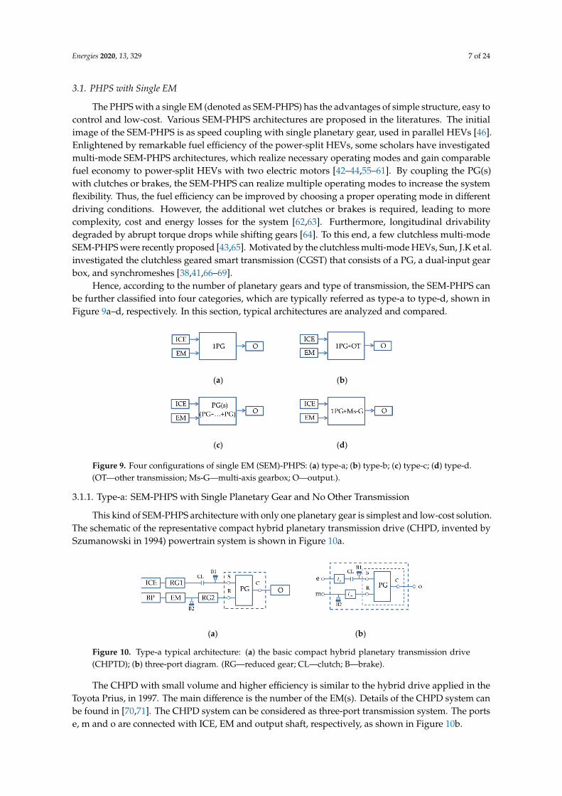
Hence, according to the number of planetary gears and type of transmission, the SEM-PHPS canbe further classified into four categories, which are typically referred as type-a to type-d, shown inFigure 9a–d, respectively. In this section, typical architectures are analyzed and compared.
Energies 2020, 13, x FOR PEER REVIEW 7 of 24
increase the system flexibility. Thus, the fuel efficiency can be improved by choosing a proper operating mode in different driving conditions. However, the additional wet clutches or brakes is required, leading to more complexity, cost and energy losses for the system [62,63]. Furthermore, longitudinal drivability degraded by abrupt torque drops while shifting gears [64]. To this end, a few clutchless multi-mode SEM-PHPS were recently proposed [65,43]. Motivated by the clutchless multi-mode HEVs, Sun, J.K et al. investigated the clutchless geared smart transmission (CGST) that consists of a PG, a dual-input gear box, and synchromeshes [38,41,66–69].
Hence, according to the number of planetary gears and type of transmission, the SEM-PHPS can be further classified into four categories, which are typically referred as type-a to type-d, shown in Figure 9a–d, respectively. In this section, typical architectures are analyzed and compared.
(a) (b)
(c) (d)
Figure 9. Four configurations of single EM (SEM)-PHPS: (a) type-a; (b) type-b; (c) type-c; (d) type-d. (OT—other transmission; Ms-G—multi-axis gearbox; O—output.).
3.1.1. Type-a: SEM-PHPS with Single Planetary Gear and No Other Transmission
This kind of SEM-PHPS architecture with only one planetary gear is simplest and low-cost solution. The schematic of the representative compact hybrid planetary transmission drive (CHPD, invented by Szumanowski in 1994) powertrain system is shown in Figure 10a.
The CHPD with small volume and higher efficiency is similar to the hybrid drive applied in the Toyota Prius, in 1997. The main difference is the number of the EM(s). Details of the CHPD system can be found in [70,71]. The CHPD system can be considered as three-port transmission system. The ports e, m and o are connected with ICE, EM and output shaft, respectively, as shown in Figure 10b.
(a) (b)
Figure 10. Type-a typical architecture: (a) the basic compact hybrid planetary transmission drive (CHPTD); (b) three-port diagram. (RG—reduced gear; CL—clutch; B—brake).
This architecture possesses simple layout, requiring smaller installation space and lower cost. However, it is only used as speed coupling, yielding worst overall performance compared to other SEM PHPS architectures.
3.1.2. Type-b: SEM-PHPS with Planetary Gear and Other Transmission
Type-b of SEM-PHPS architecture is an improvement of type-a by inserting other transmission (e.g., CVT) between planetary gear and output shaft. The added CVT is beneficial to overcome those shortcomings of type-a architecture and thus realize two ways of adjustment: the EM electric
Figure 9. Four configurations of single EM (SEM)-PHPS: (a) type-a; (b) type-b; (c) type-c; (d) type-d.(OT—other transmission; Ms-G—multi-axis gearbox; O—output.).
3.1.1. Type-a: SEM-PHPS with Single Planetary Gear and No Other Transmission
This kind of SEM-PHPS architecture with only one planetary gear is simplest and low-cost solution.The schematic of the representative compact hybrid planetary transmission drive (CHPD, invented bySzumanowski in 1994) powertrain system is shown in Figure 10a.
Energies 2020, 13, x FOR PEER REVIEW 7 of 24
increase the system flexibility. Thus, the fuel efficiency can be improved by choosing a proper operating mode in different driving conditions. However, the additional wet clutches or brakes is required, leading to more complexity, cost and energy losses for the system [62,63]. Furthermore, longitudinal drivability degraded by abrupt torque drops while shifting gears [64]. To this end, a few clutchless multi-mode SEM-PHPS were recently proposed [65,43]. Motivated by the clutchless multi-mode HEVs, Sun, J.K et al. investigated the clutchless geared smart transmission (CGST) that consists of a PG, a dual-input gear box, and synchromeshes [38,41,66–69].
Hence, according to the number of planetary gears and type of transmission, the SEM-PHPS can be further classified into four categories, which are typically referred as type-a to type-d, shown in Figure 9a–d, respectively. In this section, typical architectures are analyzed and compared.
(a) (b)
(c) (d)
Figure 9. Four configurations of single EM (SEM)-PHPS: (a) type-a; (b) type-b; (c) type-c; (d) type-d. (OT—other transmission; Ms-G—multi-axis gearbox; O—output.).
3.1.1. Type-a: SEM-PHPS with Single Planetary Gear and No Other Transmission
This kind of SEM-PHPS architecture with only one planetary gear is simplest and low-cost solution. The schematic of the representative compact hybrid planetary transmission drive (CHPD, invented by Szumanowski in 1994) powertrain system is shown in Figure 10a.
The CHPD with small volume and higher efficiency is similar to the hybrid drive applied in the Toyota Prius, in 1997. The main difference is the number of the EM(s). Details of the CHPD system can be found in [70,71]. The CHPD system can be considered as three-port transmission system. The ports e, m and o are connected with ICE, EM and output shaft, respectively, as shown in Figure 10b.
(a) (b)
Figure 10. Type-a typical architecture: (a) the basic compact hybrid planetary transmission drive (CHPTD); (b) three-port diagram. (RG—reduced gear; CL—clutch; B—brake).
This architecture possesses simple layout, requiring smaller installation space and lower cost. However, it is only used as speed coupling, yielding worst overall performance compared to other SEM PHPS architectures.
3.1.2. Type-b: SEM-PHPS with Planetary Gear and Other Transmission
Type-b of SEM-PHPS architecture is an improvement of type-a by inserting other transmission (e.g., CVT) between planetary gear and output shaft. The added CVT is beneficial to overcome those shortcomings of type-a architecture and thus realize two ways of adjustment: the EM electric
Figure 10. Type-a typical architecture: (a) the basic compact hybrid planetary transmission drive(CHPTD); (b) three-port diagram. (RG—reduced gear; CL—clutch; B—brake).
The CHPD with small volume and higher efficiency is similar to the hybrid drive applied in theToyota Prius, in 1997. The main difference is the number of the EM(s). Details of the CHPD system canbe found in [70,71]. The CHPD system can be considered as three-port transmission system. The portse, m and o are connected with ICE, EM and output shaft, respectively, as shown in Figure 10b.

Energies 2020, 13, 329 8 of 24
This architecture possesses simple layout, requiring smaller installation space and lower cost.However, it is only used as speed coupling, yielding worst overall performance compared to otherSEM PHPS architectures.
3.1.2. Type-b: SEM-PHPS with Planetary Gear and Other Transmission
Type-b of SEM-PHPS architecture is an improvement of type-a by inserting other transmission(e.g., CVT) between planetary gear and output shaft. The added CVT is beneficial to overcomethose shortcomings of type-a architecture and thus realize two ways of adjustment: the EM electricadjustment and the CVT mechanical adjustment. Generally, the metal belt is adopted in the CVTstructure. The representative Chery Arrizo 7e [37,72] hybrid system, that has been mass-producedand put into the market, is shown in Figure 11. In addition, the one-way clutch (OWC) in the systemcan diminish fuel consumption and ICE wear. Compared to CHPD system, the Chery Arrizo 7e canrealize torque coupling mode by engaging the clutch to connect the ring gear and carrier of PG together.The Arrizo 7e system can be considered as a three-port transmission system. Three ports e, m and oconnected with ICE, EM and output shaft, respectively, as shown in Figure 11b.
Energies 2020, 13, x FOR PEER REVIEW 8 of 24
adjustment and the CVT mechanical adjustment. Generally, the metal belt is adopted in the CVT structure. The representative Chery Arrizo 7e [37,72] hybrid system, that has been mass-produced and put into the market, is shown in Figure 11. In addition, the one-way clutch (OWC) in the system can diminish fuel consumption and ICE wear. Compared to CHPD system, the Chery Arrizo 7e can realize torque coupling mode by engaging the clutch to connect the ring gear and carrier of PG together. The Arrizo 7e system can be considered as a three-port transmission system. Three ports e, m and o connected with ICE, EM and output shaft, respectively, as shown in Figure 11b.
(a) (b)
Figure 11. Type-b typical architecture: (a) Arrizo 7e; (b) Three-port diagram. (OWC—one way clutch).
To further improve the comprehensive operating performance of this architecture, Hu et al. explored a single motor hybrid powertrain configuration with dual planetary gears based on Arrizo 7e by increasing the number of PG to two, details can be found in [37]. In addition, Toyota corporation launched their THS-C system in 2001 [73], consisting of THS and CVT. The THS-C system has a special single PG with two rows of planets sharing the same planetary carrier, and it is excluded from consideration of this paper.
Compared to type-a architecture, the mechanism architecture is complex and costs more, which limits its application. Moreover, a motor is required for CVT to drive the hydraulic pump in the system, which exacerbates the complexity of the system. Thus, the overall effect of type-b architecture is not so ideal.
3.1.3. Type-c: SEM-PHPS with Compound Planetary Gears and No Other Transmission
Type-c is an improved architecture of aforementioned one by adding a second PG to form a 2-DOF compound PG(s). The 2-DOF compound PG(s) is composed of two conjoined simple PG to form four separated ports, including two compound ports (formed by two interconnected members of the two PGs) and two single ports. Three of the four separated ports can be linked to three powertrain components, and the fourth port should be constrained to have deterministic output. According to the combination of three powertrain components with four ports, there are four common types of connection: type-I, type-II, type-III and type-IV, as shown in Figure 12.
(a) (b)
(c) (d)
Figure 12. Four common connections of 2-DOF compound PG(s): (a) Type-I; (b) Type-II; (c) Type-III; (d) Type-IV.
Figure 11. Type-b typical architecture: (a) Arrizo 7e; (b) Three-port diagram. (OWC—one way clutch).
To further improve the comprehensive operating performance of this architecture, Hu et al.explored a single motor hybrid powertrain configuration with dual planetary gears based on Arrizo 7eby increasing the number of PG to two, details can be found in [37]. In addition, Toyota corporationlaunched their THS-C system in 2001 [73], consisting of THS and CVT. The THS-C system has aspecial single PG with two rows of planets sharing the same planetary carrier, and it is excluded fromconsideration of this paper.
Compared to type-a architecture, the mechanism architecture is complex and costs more,which limits its application. Moreover, a motor is required for CVT to drive the hydraulic pump in thesystem, which exacerbates the complexity of the system. Thus, the overall effect of type-b architectureis not so ideal.
3.1.3. Type-c: SEM-PHPS with Compound Planetary Gears and No Other Transmission
Type-c is an improved architecture of aforementioned one by adding a second PG to form a 2-DOFcompound PG(s). The 2-DOF compound PG(s) is composed of two conjoined simple PG to formfour separated ports, including two compound ports (formed by two interconnected members of thetwo PGs) and two single ports. Three of the four separated ports can be linked to three powertraincomponents, and the fourth port should be constrained to have deterministic output. According tothe combination of three powertrain components with four ports, there are four common types ofconnection: type-I, type-II, type-III and type-IV, as shown in Figure 12.
In this type of SEM-PHPS system, clutches and brakes are employed to control the multipleoperation modes of the system. Thus, the fuel efficiency can be improved by choosing a properoperational mode depending on the driving conditions. Generally, the number of clutches and brakesused in system should not exceed four. The four existing specific architectures, corresponding with thefour common types in Figure 12, are shown in Figure 13.

Energies 2020, 13, 329 9 of 24
Energies 2020, 13, x FOR PEER REVIEW 8 of 24
adjustment and the CVT mechanical adjustment. Generally, the metal belt is adopted in the CVT structure. The representative Chery Arrizo 7e [37,72] hybrid system, that has been mass-produced and put into the market, is shown in Figure 11. In addition, the one-way clutch (OWC) in the system can diminish fuel consumption and ICE wear. Compared to CHPD system, the Chery Arrizo 7e can realize torque coupling mode by engaging the clutch to connect the ring gear and carrier of PG together. The Arrizo 7e system can be considered as a three-port transmission system. Three ports e, m and o connected with ICE, EM and output shaft, respectively, as shown in Figure 11b.
(a) (b)
Figure 11. Type-b typical architecture: (a) Arrizo 7e; (b) Three-port diagram. (OWC—one way clutch).
To further improve the comprehensive operating performance of this architecture, Hu et al. explored a single motor hybrid powertrain configuration with dual planetary gears based on Arrizo 7e by increasing the number of PG to two, details can be found in [37]. In addition, Toyota corporation launched their THS-C system in 2001 [73], consisting of THS and CVT. The THS-C system has a special single PG with two rows of planets sharing the same planetary carrier, and it is excluded from consideration of this paper.
Compared to type-a architecture, the mechanism architecture is complex and costs more, which limits its application. Moreover, a motor is required for CVT to drive the hydraulic pump in the system, which exacerbates the complexity of the system. Thus, the overall effect of type-b architecture is not so ideal.
3.1.3. Type-c: SEM-PHPS with Compound Planetary Gears and No Other Transmission
Type-c is an improved architecture of aforementioned one by adding a second PG to form a 2-DOF compound PG(s). The 2-DOF compound PG(s) is composed of two conjoined simple PG to form four separated ports, including two compound ports (formed by two interconnected members of the two PGs) and two single ports. Three of the four separated ports can be linked to three powertrain components, and the fourth port should be constrained to have deterministic output. According to the combination of three powertrain components with four ports, there are four common types of connection: type-I, type-II, type-III and type-IV, as shown in Figure 12.
(a) (b)
(c) (d)
Figure 12. Four common connections of 2-DOF compound PG(s): (a) Type-I; (b) Type-II; (c) Type-III; (d) Type-IV.
Figure 12. Four common connections of 2-DOF compound PG(s): (a) Type-I; (b) Type-II; (c) Type-III;(d) Type-IV.
Energies 2020, 13, x FOR PEER REVIEW 9 of 24
In this type of SEM-PHPS system, clutches and brakes are employed to control the multiple operation modes of the system. Thus, the fuel efficiency can be improved by choosing a proper operational mode depending on the driving conditions. Generally, the number of clutches and brakes used in system should not exceed four. The four existing specific architectures, corresponding with the four common types in Figure 12, are shown in Figure 13.
(a) (b)
(c) (d)
Figure 13. Type-c typical architecture developed by (a) Tsai; (b) Zhu; (c) Chachra; (d) Tsai.
Figure 13a shows one of type-c with six operation modes proposed by Tsai et al. [44]. In this system, the EM and output shaft are connected to the compound PG(s) through two compound ports. The ICE is connected to one of the single ports via a clutch and the other is constrained by a brake. Tsai et al. patented a SEM-PHPS [57] architecture as shown in Figure 13d with five major operating modes, detailed analysis can be found in [55]. Compared to the previous architecture shown in Figure 13a, the main difference is that the ICE shaft can be coupled to the fourth free port via the clutch CL2. In addition, for further improvement, Tsai et al. [58] patented another SEM-PHPS architecture with five basic operating modes, and details can be found in [74]. In the new version system, the electric motor (EM) is integrated coaxially with the 2-DOF compound PG(s), the internal combustion engine (ICE) shaft can be coupled to the electric motor shaft through a clutch. The layout of the system is similar with the one proposed by Zhu et al. shown in Figure 13b, and the main difference is whether the electric motor is integrated coaxially with the PG(s). Compared to the three previous architectures developed by Tsai et al., the motor-integrated hybrid system can be incorporated not only in front-wheel-drive but also in rear-wheel-drive vehicles. However, it is not easy to realize in practice.
Figure 13b shows the architecture proposed by Zhu et al. [42], with sixteen basic operation modes. In this system, the ICE and output shaft are connected to the compound PG(s) through two compound ports. The EM is connected to one of the single ports directly and the other is constrained by a brake. In addition, the ICE shaft can be coupled to the EM shaft through the clutch CL2. In this architecture, the connection of the compound PG(s) is identical to that widely used in several conventional four-speed ATs. The cost and reliability of this architecture are superior to other completely redesigned transmissions because of using the components of the traditional four-speed ATs. In addition, the fuel economy potential of this architecture, proved by Zhu et al., is comparable to a benchmark “THS II-like” vehicle.
The SEM-PHPS architecture patented by Chachra et al. [60], is shown in Figure 13c. In this system, the output shaft is connected to one compound port and the ICE is connected to one single port via a clutch, while the EM can be coupled to the other two remainder ports through a clutch. This architecture can limit the re-circulating power in the system to a fraction of the input power.
These four hybrid systems can be considered as three-port system. The ports e, m and o are connected with three powertrain components ICE, EM and output shaft, respectively, as shown in Figure 14.
ICE
PG1 OS1
C1
R1
PG2R2
C2
S2CL1
EM
B1
B2CL2
ICE PG1 OC1
S1
R1
PG2S2
C2
R2
CL1
B1B2
EM
ICE
PG1 OS1
R1
C1
PG2R2
S2
C2
CL2
B2
EM
B1
CL1B2 B1
ICE PG1C1
S1
R1
PG2S2
C2
R2
CL1
EM
O
CL2
Figure 13. Type-c typical architecture developed by (a) Tsai; (b) Zhu; (c) Chachra; (d) Tsai.
Figure 13a shows one of type-c with six operation modes proposed by Tsai et al. [44]. In thissystem, the EM and output shaft are connected to the compound PG(s) through two compoundports. The ICE is connected to one of the single ports via a clutch and the other is constrained bya brake. Tsai et al. patented a SEM-PHPS [57] architecture as shown in Figure 13d with five majoroperating modes, detailed analysis can be found in [55]. Compared to the previous architecture shownin Figure 13a, the main difference is that the ICE shaft can be coupled to the fourth free port viathe clutch CL2. In addition, for further improvement, Tsai et al. [58] patented another SEM-PHPSarchitecture with five basic operating modes, and details can be found in [74]. In the new versionsystem, the electric motor (EM) is integrated coaxially with the 2-DOF compound PG(s), the internalcombustion engine (ICE) shaft can be coupled to the electric motor shaft through a clutch. The layout ofthe system is similar with the one proposed by Zhu et al. shown in Figure 13b, and the main differenceis whether the electric motor is integrated coaxially with the PG(s). Compared to the three previousarchitectures developed by Tsai et al., the motor-integrated hybrid system can be incorporated not onlyin front-wheel-drive but also in rear-wheel-drive vehicles. However, it is not easy to realize in practice.
Figure 13b shows the architecture proposed by Zhu et al. [42], with sixteen basic operationmodes. In this system, the ICE and output shaft are connected to the compound PG(s) throughtwo compound ports. The EM is connected to one of the single ports directly and the other isconstrained by a brake. In addition, the ICE shaft can be coupled to the EM shaft through the clutchCL2. In this architecture, the connection of the compound PG(s) is identical to that widely used inseveral conventional four-speed ATs. The cost and reliability of this architecture are superior to othercompletely redesigned transmissions because of using the components of the traditional four-speed

Energies 2020, 13, 329 10 of 24
ATs. In addition, the fuel economy potential of this architecture, proved by Zhu et al., is comparable toa benchmark “THS II-like” vehicle.
The SEM-PHPS architecture patented by Chachra et al. [60], is shown in Figure 13c. In thissystem, the output shaft is connected to one compound port and the ICE is connected to one singleport via a clutch, while the EM can be coupled to the other two remainder ports through a clutch.This architecture can limit the re-circulating power in the system to a fraction of the input power.
These four hybrid systems can be considered as three-port system. The ports e, m and o areconnected with three powertrain components ICE, EM and output shaft, respectively, as shown inFigure 14.
Energies 2020, 13, x FOR PEER REVIEW 10 of 24
Compared to type-a and type-b architectures aforementioned, this type architecture can create a more fuel-efficient multi-mode PHPS. However, additional wet clutches and brakes using hydraulic components increase the complexity and cost of system.
(a) (b)
(c) (d)
Figure 14. Port diagram of typical architecture developed by (a) Tsai; (b) Zhu; (c) Chachra; (d) Tsai.
3.1.4. Type-d: SEM-PHPS with Single Planetary Gear and Multiple Input Axis Gearboxes
Type-d, using multi-axis gearboxes instead of the second PG in type-c architecture, can realize multi-mode operation. This architecture is inspired by the automatic geared transmission (AGT). The AGT with no fluid coupler can gain better fuel economy than the CVT hybrid powertrain. However, conventional AGT hybrid vehicles have some disadvantages. For example, the AGT with one axle and single clutch [75] has a longer shifting time, which makes the driver uncomfortable. To prevent the power interruption, the AGT is devised by two axles with dual clutch (DCT) [76]. However, a general wet-clutch DCT has a higher energy loss and short lifetime. Therefore, other AGTs using a single planetary gear, with dual input axes like the DCT, were developed. Specifically, the PG combined with attached motor allows flexible torque or speed control depending on the number of connections to the dual input axes of the transmissions.
This type of architecture is mainly equipped with single PG, multi-axis gearboxes and synchromeshes. The multi-axis gearbox has two input axes connected with two ports of PG and one output axis linked to the output port of the system. Generally, the multi-axis gearbox is composed of various gear sets, which decide gear ratio of each gear step in the system. It is noted that the synchromesh in multi-axis gearboxes engages or disengages the gear mesh for gear shifting operation. In fact, various operational modes can be generated depending on the engagement combination of synchromeshes. In addition to being in the multi-axis gearboxes, the synchromesh may also be located at the port of PG connected with ICE or EM, as shown in Figure 15b,c.
This type architecture can be realized in various forms. Three representative schemes: one hybrid drive train (HDT) [59,77] with clutch (developed by Bachmann M), two so-called clutchless system—Hitachi active shift transmission (HAST) [65] (developed by Teshima T) and clutchless geared smart transmission (CGST) [67] (developed by Y-S Yoon), are shown in Figure 15a–c respectively. These three systems, with different type of the clutch and location of the synchromeshes, are different as the configurations of multi-axis gearboxes differ.
In the HDT system, the ICE is directly connected to one input axis of the multi-axis gearbox. Thus, it requires a clutch at the back of the ICE for starting the vehicle from the standing-still. The HAST system temporarily changes the power flow from the gear-train to a path through the PG while shifting gears without requiring a clutch. However, there are two changes in the power flow, and it inevitably requires long gear-trains. The CGST system, with similar multi-axis gearbox structure in HDT system, has a compact structure and can remarkably shorten the length of the power-train
PG1S1
C1
R1
PG2R2
C2
S2CL1
B1
B2
CL2
m
e
oe
m
PG1C1
S1
R1
PG2S2
C2
R2
CL1
B2B1
o
PG1S1
R1
C1
PG2R2
S2
C2
CL2
B2
B1
CL1
m
e
o e
m
PG1C1
S1
R1
PG2S2
C2
R2
CL1
B2B1
o
Figure 14. Port diagram of typical architecture developed by (a) Tsai; (b) Zhu; (c) Chachra; (d) Tsai.
Compared to type-a and type-b architectures aforementioned, this type architecture can create amore fuel-efficient multi-mode PHPS. However, additional wet clutches and brakes using hydrauliccomponents increase the complexity and cost of system.
3.1.4. Type-d: SEM-PHPS with Single Planetary Gear and Multiple Input Axis Gearboxes
Type-d, using multi-axis gearboxes instead of the second PG in type-c architecture, can realizemulti-mode operation. This architecture is inspired by the automatic geared transmission (AGT).The AGT with no fluid coupler can gain better fuel economy than the CVT hybrid powertrain. However,conventional AGT hybrid vehicles have some disadvantages. For example, the AGT with one axle andsingle clutch [75] has a longer shifting time, which makes the driver uncomfortable. To prevent thepower interruption, the AGT is devised by two axles with dual clutch (DCT) [76]. However, a generalwet-clutch DCT has a higher energy loss and short lifetime. Therefore, other AGTs using a singleplanetary gear, with dual input axes like the DCT, were developed. Specifically, the PG combined withattached motor allows flexible torque or speed control depending on the number of connections to thedual input axes of the transmissions.
This type of architecture is mainly equipped with single PG, multi-axis gearboxes andsynchromeshes. The multi-axis gearbox has two input axes connected with two ports of PG and oneoutput axis linked to the output port of the system. Generally, the multi-axis gearbox is composedof various gear sets, which decide gear ratio of each gear step in the system. It is noted that thesynchromesh in multi-axis gearboxes engages or disengages the gear mesh for gear shifting operation.In fact, various operational modes can be generated depending on the engagement combination ofsynchromeshes. In addition to being in the multi-axis gearboxes, the synchromesh may also be locatedat the port of PG connected with ICE or EM, as shown in Figure 15b,c.

Energies 2020, 13, 329 11 of 24
Energies 2020, 13, x FOR PEER REVIEW 11 of 24
compared with HAST system. Table 3 compares the three hybrid systems and DCT system. As listed in Table 3, the CGST hybrid system has better comprehensive performance than the other systems. These three hybrid systems can also be considered as three-port system. Three ports e, m and o are connected with three powertrain components ICE, EM and output shaft, respectively, as shown in Figure 16.
(a)
(b)
(c)
Figure 15. Type-d SEM PHPS architecture: (a) hybrid drive train (HDT); (b) Hitachi active shift transmission (HAST); (c) clutchless geared smart transmission (CGST). (Ms-G—multi-axis gearbox; FG—fixed gear; SM—synchromeshes; Ps—path switch; CL—clutch.).
Table 3. Comparison of the three hybrid transmission systems and the dal clutch (DCT) system.
HEV Class.
CL No. PG No. I-a No. P-p No. Sy. No. Shift
Speed Shift
Impact P-m
HAST 0 1 2 4 5 - + + HTD 1 1 2 3 4 - - 0 CGST 0 1 2 2 5 0 + + DCT 2 0 2 2 0 + - 0
Class.—classification; No.—number; CL—clutch; I-a—input axis; P-p—power paths; Sy.—synchromesh; P-m—power merge.
(a)
PG
S
RC
SMPG
Ms-G OAxis1
Axis2
BP EM
ICE
FGe
FGm
SMICE
SM1/SM3
SM2/SM4
PG
R
SC
ei
e
moMs-G
Axis1
Axis2
mi
1*i
2 *i
Figure 15. Type-d SEM PHPS architecture: (a) hybrid drive train (HDT); (b) Hitachi active shifttransmission (HAST); (c) clutchless geared smart transmission (CGST). (Ms-G—multi-axis gearbox;FG—fixed gear; SM—synchromeshes; Ps—path switch; CL—clutch.).
This type architecture can be realized in various forms. Three representative schemes: onehybrid drive train (HDT) [59,77] with clutch (developed by Bachmann M), two so-called clutchlesssystem—Hitachi active shift transmission (HAST) [65] (developed by Teshima T) and clutchless gearedsmart transmission (CGST) [67] (developed by Y-S Yoon), are shown in Figure 15a–c respectively. Thesethree systems, with different type of the clutch and location of the synchromeshes, are different as theconfigurations of multi-axis gearboxes differ.
In the HDT system, the ICE is directly connected to one input axis of the multi-axis gearbox. Thus,it requires a clutch at the back of the ICE for starting the vehicle from the standing-still. The HASTsystem temporarily changes the power flow from the gear-train to a path through the PG while shiftinggears without requiring a clutch. However, there are two changes in the power flow, and it inevitablyrequires long gear-trains. The CGST system, with similar multi-axis gearbox structure in HDT system,has a compact structure and can remarkably shorten the length of the power-train compared withHAST system. Table 3 compares the three hybrid systems and DCT system. As listed in Table 3,the CGST hybrid system has better comprehensive performance than the other systems. These threehybrid systems can also be considered as three-port system. Three ports e, m and o are connected withthree powertrain components ICE, EM and output shaft, respectively, as shown in Figure 16.
This type architecture, different from type-c that adopted brakes or clutches, especially forthe clutchless systems using synchromeshes and EM instead of clutches, has higher fuel efficiencyand control flexibility. However, the use of the multi-axis gearboxes increases the length of thepowertrain. As a summary, Table 4 listed the main advantages and disadvantages of the four type ofSEM-PHPS architectures.

Energies 2020, 13, 329 12 of 24
Table 3. Comparison of the three hybrid transmission systems and the dal clutch (DCT) system.
HEV Class. CL No. PG No. I-a No. P-p No. Sy. No. Shift Speed Shift Impact P-m
HAST 0 1 2 4 5 - + +HTD 1 1 2 3 4 - - 0CGST 0 1 2 2 5 0 + +DCT 2 0 2 2 0 + - 0
Class.—classification; No.—number; CL—clutch; I-a—input axis; P-p—power paths; Sy.—synchromesh;P-m—power merge.
Energies 2020, 13, x FOR PEER REVIEW 11 of 24
compared with HAST system. Table 3 compares the three hybrid systems and DCT system. As listed in Table 3, the CGST hybrid system has better comprehensive performance than the other systems. These three hybrid systems can also be considered as three-port system. Three ports e, m and o are connected with three powertrain components ICE, EM and output shaft, respectively, as shown in Figure 16.
(a)
(b)
(c)
Figure 15. Type-d SEM PHPS architecture: (a) hybrid drive train (HDT); (b) Hitachi active shift transmission (HAST); (c) clutchless geared smart transmission (CGST). (Ms-G—multi-axis gearbox; FG—fixed gear; SM—synchromeshes; Ps—path switch; CL—clutch.).
Table 3. Comparison of the three hybrid transmission systems and the dal clutch (DCT) system.
HEV Class.
CL No. PG No. I-a No. P-p No. Sy. No. Shift
Speed Shift
Impact P-m
HAST 0 1 2 4 5 - + + HTD 1 1 2 3 4 - - 0 CGST 0 1 2 2 5 0 + + DCT 2 0 2 2 0 + - 0
Class.—classification; No.—number; CL—clutch; I-a—input axis; P-p—power paths; Sy.—synchromesh; P-m—power merge.
(a)
PG
S
RC
SMPG
Ms-G OAxis1
Axis2
BP EM
ICE
FGe
FGm
SMICE
SM1/SM3
SM2/SM4
PG
R
SC
ei
e
moMs-G
Axis1
Axis2
mi
1*i
2 *i
Energies 2020, 13, x FOR PEER REVIEW 12 of 24
(b)
(c)
Figure 16. Port diagram of a typical architecture: (a) HDT; (b) HAST; (c) CGST.
This type architecture, different from type-c that adopted brakes or clutches, especially for the clutchless systems using synchromeshes and EM instead of clutches, has higher fuel efficiency and control flexibility. However, the use of the multi-axis gearboxes increases the length of the powertrain. As a summary, Table 4 listed the main advantages and disadvantages of the four type of SEM-PHPS architectures.
Table 4. Comparison of four types of SEM-PHPS architectures.
Arc. PG. OT AC OM Advantages Disadvantages Lit. Type-
a 1 - 2 S simplest and low-cost used as speed coupling only [70,71]
Type-b
1 Continuously
variable transmission (CVT)
3 M speed and torque
adjustment CVT increases system
complexity [37,72]
Type-c
2 - 3/4 M more fuel-efficient and higher control
flexibility
additional wet clutches and brakes, more complexity
and costs [42,44,57,60]
Type-d
1 Ms-G 0/1 M better fuel efficiency and higher control
flexibility
increase the length of the power-train
[59,65,67]
Arc.—architectures; PG.—PG number; OT—other transmission; AC—additional clutches; S—single; OM—operating mode; M—multiple; Ms-G—multi-axis gear; Lit.—literature.
3.2. PHPS with Two EMs
The PHPS with two EMs (denoted as TEM-PHPS), that is composed of an internal combustion engine, two electric motors and planetary gear(s), is the mainstream in HEV market [26]. With the help of a planetary gear system and the two electric motors, the ICE speed can be decoupled from wheels speed to enable ICE operating efficiently in a wide range of vehicle speed. This kind of CVT is referred to as e-CVT by researchers. However, due to the unavoidable energy conversion between two electric motors (from the generator to the motor), the TEM-PHPS system has greater energy losses compared to SEM-PHPS in highway driving conditions.
At present, a variety of TEM-PHPS architectures have been commercialized. Three of the top selling architectures available in today’s HEV market, Toyota Prius, Chevrolet Volt and Ford Ford Hybrid System (FHS), all began with single-PG architectures. In recent years, power-split HEVs tend to use two PG(s) since double-PG(s) HEVs appear to have better performance than single-PG one, the above two currently popular HEVs were both changed to double-PG designs in 2010 and 2015 [78], respectively. Besides the vehicles mentioned above, another typical double-PG HEV introduced
PG
C
SR
e
moMs-G
Axis1
Axis21*i
2 *i
SMPG
PG
R
SC
ei
e
moMs-G
Axis1
Axis2
mi
1*i
2 *i
SMPG
Figure 16. Port diagram of a typical architecture: (a) HDT; (b) HAST; (c) CGST.
Table 4. Comparison of four types of SEM-PHPS architectures.
Arc. PG. OT AC OM Advantages Disadvantages Lit.
Type-a 1 - 2 S simplest andlow-cost
used as speed couplingonly [70,71]
Type-b 1Continuously
variabletransmission (CVT)
3 M speed and torqueadjustment
CVT increases systemcomplexity [37,72]
Type-c 2 - 3/4 Mmore fuel-efficientand higher control
flexibility
additional wet clutchesand brakes, more
complexity and costs[42,44,57,60]
Type-d 1 Ms-G 0/1 Mbetter fuel efficiencyand higher control
flexibility
increase the length ofthe power-train [59,65,67]
Arc.—architectures; PG.—PG number; OT—other transmission; AC—additional clutches; S—single; OM—operatingmode; M—multiple; Ms-G—multi-axis gear; Lit.—literature.
3.2. PHPS with Two EMs
The PHPS with two EMs (denoted as TEM-PHPS), that is composed of an internal combustionengine, two electric motors and planetary gear(s), is the mainstream in HEV market [26]. With the help

Energies 2020, 13, 329 13 of 24
of a planetary gear system and the two electric motors, the ICE speed can be decoupled from wheelsspeed to enable ICE operating efficiently in a wide range of vehicle speed. This kind of CVT is referredto as e-CVT by researchers. However, due to the unavoidable energy conversion between two electricmotors (from the generator to the motor), the TEM-PHPS system has greater energy losses comparedto SEM-PHPS in highway driving conditions.
At present, a variety of TEM-PHPS architectures have been commercialized. Three of the topselling architectures available in today’s HEV market, Toyota Prius, Chevrolet Volt and Ford FordHybrid System (FHS), all began with single-PG architectures. In recent years, power-split HEVstend to use two PG(s) since double-PG(s) HEVs appear to have better performance than single-PGone, the above two currently popular HEVs were both changed to double-PG designs in 2010 and2015 [78], respectively. Besides the vehicles mentioned above, another typical double-PG HEVintroduced by General Motors (GM) has two e-CVT modes, known as the Allison hybrid system(AHS) [79]. GM announced the second generation of AHS later (called “two-mode hybrid”) with threeplanetary gears and four clutches [80]. According to the definition by GM, “the two-mode” refersto the combination of both e-CVT modes and fixed gear ratio modes. Compared to single-PG anddouble-PG(s) HEVs, multi-PG(s) HEVs can provide more design flexibility by switching clutch statesto achieve multiple operating modes. By comparing multi-mode hybrid powertrains with multiplePG(s), Zhuang et al. considered that triple-PG hybrids have a slight efficiency improvement and betterpower performance compared to double-PG [81]. It is clear that the number of the PG(s) is one of thekey factors influencing the performance of the TEM-PHPS system.
Therefore, according to the number of PG(s) and type of transmission, the TEM-PHPS can beclassified into four main categories, which are typically referred as type-a to type-d, shown in Figure 17,respectively. In this section, representative architectures of each type are analyzed and compared.
Energies 2020, 13, x FOR PEER REVIEW 13 of 24
by General Motors (GM) has two e-CVT modes, known as the Allison hybrid system (AHS) [79]. GM announced the second generation of AHS later (called “two-mode hybrid”) with three planetary gears and four clutches [80]. According to the definition by GM, “the two-mode” refers to the combination of both e-CVT modes and fixed gear ratio modes. Compared to single-PG and double-PG(s) HEVs, multi-PG(s) HEVs can provide more design flexibility by switching clutch states to achieve multiple operating modes. By comparing multi-mode hybrid powertrains with multiple PG(s), Zhuang et al. considered that triple-PG hybrids have a slight efficiency improvement and better power performance compared to double-PG [81]. It is clear that the number of the PG(s) is one of the key factors influencing the performance of the TEM-PHPS system.
Therefore, according to the number of PG(s) and type of transmission, the TEM-PHPS can be classified into four main categories, which are typically referred as type-a to type-d, shown in Figure 17, respectively. In this section, representative architectures of each type are analyzed and compared.
(a) (b)
(c) (d)
Figure 17. Four architecture types of two EMs PHP: (a) type-a; (b) type-b; (c) type-c; (d) type-d. (OT—other transmission; M-PG(s)—multi-planetary gear(s)).
3.2.1. Type-a: TEM-PHPS with Single Planetary Gear and No Other Transmission
This type of architecture is the most compact and low-cost of TEM-PHPS to realize the function of e-CVT. This architecture can be further included two categories: clutchless and with a clutch system. Toyota Prius [82] and Chevrolet Volt [83] are the most widely-known examples available on the market with single PG, as shown in Figure 18. However, these two systems can be very distinct in different component arrangements. The THS configuration, as shown in Figure 18a, in which the output shaft and the EM2 are connected to the same port of the planetary gear (known as input-split) without clutch, is called as clutchless system in this paper. For the Volt system, as shown in Figure 18b, where the ICE and the EM2 shared the same port of the planetary gear (known as output-split), using three clutches to realize four operating modes, is called the clutch system here. As shown in Figure 7b, the two hybrid systems can be considered as three-port system despite of having four powertrain components. Three ports e, m1 and o connected with three powertrain components ICE, EM1 and output shaft, respectively, as shown in Figure 18c,d. The function of EM2 is to supplement the ICE torque, thus allowing the ICE to operate in the high-efficiency regions.
(a) (b)
ICE
EM11PG
O
EM2
ICE
EM11PG+OT
O
EM2
ICE
EM12PG(s)
O
EM2
ICE
EM1M-PG(s)
O
EM2
Figure 17. Four architecture types of two EMs PHP: (a) type-a; (b) type-b; (c) type-c; (d) type-d.(OT—other transmission; M-PG(s)—multi-planetary gear(s)).
3.2.1. Type-a: TEM-PHPS with Single Planetary Gear and No Other Transmission
This type of architecture is the most compact and low-cost of TEM-PHPS to realize the function ofe-CVT. This architecture can be further included two categories: clutchless and with a clutch system.Toyota Prius [82] and Chevrolet Volt [83] are the most widely-known examples available on the marketwith single PG, as shown in Figure 18. However, these two systems can be very distinct in differentcomponent arrangements. The THS configuration, as shown in Figure 18a, in which the output shaftand the EM2 are connected to the same port of the planetary gear (known as input-split) without clutch,is called as clutchless system in this paper. For the Volt system, as shown in Figure 18b, where the ICEand the EM2 shared the same port of the planetary gear (known as output-split), using three clutchesto realize four operating modes, is called the clutch system here. As shown in Figure 7b, the twohybrid systems can be considered as three-port system despite of having four powertrain components.Three ports e, m1 and o connected with three powertrain components ICE, EM1 and output shaft,
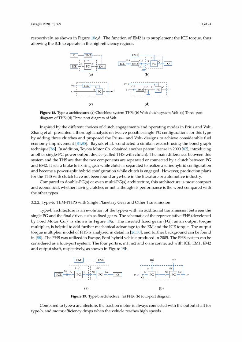
Energies 2020, 13, 329 14 of 24
respectively, as shown in Figure 18c,d. The function of EM2 is to supplement the ICE torque, thusallowing the ICE to operate in the high-efficiency regions.
Energies 2020, 13, x FOR PEER REVIEW 13 of 24
by General Motors (GM) has two e-CVT modes, known as the Allison hybrid system (AHS) [79]. GM announced the second generation of AHS later (called “two-mode hybrid”) with three planetary gears and four clutches [80]. According to the definition by GM, “the two-mode” refers to the combination of both e-CVT modes and fixed gear ratio modes. Compared to single-PG and double-PG(s) HEVs, multi-PG(s) HEVs can provide more design flexibility by switching clutch states to achieve multiple operating modes. By comparing multi-mode hybrid powertrains with multiple PG(s), Zhuang et al. considered that triple-PG hybrids have a slight efficiency improvement and better power performance compared to double-PG [81]. It is clear that the number of the PG(s) is one of the key factors influencing the performance of the TEM-PHPS system.
Therefore, according to the number of PG(s) and type of transmission, the TEM-PHPS can be classified into four main categories, which are typically referred as type-a to type-d, shown in Figure 17, respectively. In this section, representative architectures of each type are analyzed and compared.
(a) (b)
(c) (d)
Figure 17. Four architecture types of two EMs PHP: (a) type-a; (b) type-b; (c) type-c; (d) type-d. (OT—other transmission; M-PG(s)—multi-planetary gear(s)).
3.2.1. Type-a: TEM-PHPS with Single Planetary Gear and No Other Transmission
This type of architecture is the most compact and low-cost of TEM-PHPS to realize the function of e-CVT. This architecture can be further included two categories: clutchless and with a clutch system. Toyota Prius [82] and Chevrolet Volt [83] are the most widely-known examples available on the market with single PG, as shown in Figure 18. However, these two systems can be very distinct in different component arrangements. The THS configuration, as shown in Figure 18a, in which the output shaft and the EM2 are connected to the same port of the planetary gear (known as input-split) without clutch, is called as clutchless system in this paper. For the Volt system, as shown in Figure 18b, where the ICE and the EM2 shared the same port of the planetary gear (known as output-split), using three clutches to realize four operating modes, is called the clutch system here. As shown in Figure 7b, the two hybrid systems can be considered as three-port system despite of having four powertrain components. Three ports e, m1 and o connected with three powertrain components ICE, EM1 and output shaft, respectively, as shown in Figure 18c,d. The function of EM2 is to supplement the ICE torque, thus allowing the ICE to operate in the high-efficiency regions.
(a) (b)
(c) (d)
ICE
EM11PG
O
EM2
ICE
EM11PG+OT
O
EM2
ICE
EM12PG(s)
O
EM2
ICE
EM1M-PG(s)
O
EM2
Figure 18. Type-a architecture: (a) Clutchless system-THS; (b) With clutch system-Volt; (c) Three-portdiagram of THS; (d) Three-port diagram of Volt.
Inspired by the different choices of clutch engagements and operating modes in Prius and Volt,Zhang et al. presented a thorough analysis on twelve possible single-PG configurations for this typeby adding three clutches and proposed the Prius+ and Volt- designs to achieve considerable fueleconomy improvement [84,85]. Bayrak et al. conducted a similar research using the bond graphtechnique [86]. In addition, Toyota Motor Co. obtained another patent license in 2000 [87], introducinganother single-PG power output device (called THS with clutch). The main differences between thissystem and the THS are that the two components are separated or connected by a clutch between PGand EM2. It sets a brake to fix ring gear while clutch is separated to realize a series hybrid configurationand become a power-split hybrid configuration while clutch is engaged. However, production plansfor the THS with clutch have not been found anywhere in the literature or automotive industry.
Compared to double-PG(s) or even multi-PG(s) architecture, this architecture is most compactand economical, whether having clutches or not, although its performance is the worst compared withthe other types.
3.2.2. Type-b: TEM-PHPS with Single Planetary Gear and Other Transmission
Type-b architecture is an evolution of the type-a with an additional transmission between thesingle PG and the final drive, such as fixed gears. The schematic of the representative FHS (developedby Ford Motor Co.) is shown in Figure 19a. The inserted fixed gears (FG), as an output torquemultiplier, is helpful to add further mechanical advantage to the EM and the ICE torque. The outputtorque multiplier model of FHS is analyzed in detail in [26,50], and further background can be foundin [88]. The FHS was utilized in Escape, Ford hybrid vehicle produced in 2005. The FHS system can beconsidered as a four-port system. The four ports e, m1, m2 and o are connected with ICE, EM1, EM2and output shaft, respectively, as shown in Figure 19b.
Energies 2020, 13, x FOR PEER REVIEW 14 of 24
(c) (d)
Figure 18. Type-a architecture: (a) Clutchless system-THS; (b) With clutch system-Volt; (c) Three-port diagram of THS; (d) Three-port diagram of Volt.
Inspired by the different choices of clutch engagements and operating modes in Prius and Volt, Zhang et al. presented a thorough analysis on twelve possible single-PG configurations for this type by adding three clutches and proposed the Prius+ and Volt- designs to achieve considerable fuel economy improvement [84,85]. Bayrak et al. conducted a similar research using the bond graph technique [86]. In addition, Toyota Motor Co. obtained another patent license in 2000 [87], introducing another single-PG power output device (called THS with clutch). The main differences between this system and the THS are that the two components are separated or connected by a clutch between PG and EM2. It sets a brake to fix ring gear while clutch is separated to realize a series hybrid configuration and become a power-split hybrid configuration while clutch is engaged. However, production plans for the THS with clutch have not been found anywhere in the literature or automotive industry.
Compared to double-PG(s) or even multi-PG(s) architecture, this architecture is most compact and economical, whether having clutches or not, although its performance is the worst compared with the other types.
3.2.2. Type-b: TEM-PHPS with Single Planetary Gear and Other Transmission
Type-b architecture is an evolution of the type-a with an additional transmission between the single PG and the final drive, such as fixed gears. The schematic of the representative FHS (developed by Ford Motor Co.) is shown in Figure 19a. The inserted fixed gears (FG), as an output torque multiplier, is helpful to add further mechanical advantage to the EM and the ICE torque. The output torque multiplier model of FHS is analyzed in detail in [26,50], and further background can be found in [88]. The FHS was utilized in Escape, Ford hybrid vehicle produced in 2005. The FHS system can be considered as a four-port system. The four ports e, m1, m2 and o are connected with ICE, EM1, EM2 and output shaft, respectively, as shown in Figure 19b.
(a) (b)
Figure 19. Type-b architecture: (a) FHS; (b) four-port diagram.
Compared to type-a architecture, the traction motor is always connected with the output shaft for type-b, and motor efficiency drops when the vehicle reaches high speeds.
3.2.3. Type-c: TEM-PHPS with Two Planetary Gears
This type of TEM-PHPS architecture, improved based on type-b architecture by replacing the fixed gears with a second planetary gear, can be further divided into single-mode and two-mode depending on the function of the additional planetary gear.
A typical single-mode architecture with dual-PG, launched by Toyota Motor Co. in 2005 [89], as shown in Figure 20a, is applied in Lexus RX400h, Camry and Lexus Highlander [90]. In this hybrid system, the dual-PG is conjoined together through the ring gear of two PG(s) forming one compound port where the power is coupled and transferred to the output drive shaft. In addition to the compound port, the dual-PG has four separated ports, and three of them are linked to ICE, EM1 and
ICE PGC
SR
EM1 EM2
FGN3
N1N2
OCL
PGC
SR
FGN3
N1N2
oe
m2m1
CL
Figure 19. Type-b architecture: (a) FHS; (b) four-port diagram.
Compared to type-a architecture, the traction motor is always connected with the output shaft fortype-b, and motor efficiency drops when the vehicle reaches high speeds.

Energies 2020, 13, 329 15 of 24
3.2.3. Type-c: TEM-PHPS with Two Planetary Gears
This type of TEM-PHPS architecture, improved based on type-b architecture by replacing the fixedgears with a second planetary gear, can be further divided into single-mode and two-mode dependingon the function of the additional planetary gear.
A typical single-mode architecture with dual-PG, launched by Toyota Motor Co. in 2005 [89],as shown in Figure 20a, is applied in Lexus RX400h, Camry and Lexus Highlander [90]. In thishybrid system, the dual-PG is conjoined together through the ring gear of two PG(s) forming onecompound port where the power is coupled and transferred to the output drive shaft. In addition tothe compound port, the dual-PG has four separated ports, and three of them are linked to ICE, EM1and EM2, respectively, and the fourth port (C2) is constrained via a brake (B) to have deterministicoutput. Furthermore, the ICE is connected to the port of dual-PG via the torsional damper (TD).Hermance et al. conducted research on this architecture [91]. Compared with the THS system belongingto type-a of TEM-PHPS, this architecture can achieve better power and off-road. However, it stillhas only one operating mode due to the second PG is a simple gear mechanism [92]. In addition tothis system with dual-PG, Toyota launched a special dual-planetary (a simple PG and a Ravigneauxplanetary) configuration so-called THS-II [93], used in Lexus GS450h, Harrier, Kluger and LexusLS600hL, which can achieve two different operation modes to fulfil different speed cycles.
Energies 2020, 13, x FOR PEER REVIEW 15 of 24
EM2, respectively, and the fourth port (C2) is constrained via a brake (B) to have deterministic output. Furthermore, the ICE is connected to the port of dual-PG via the torsional damper (TD). Hermance et al. conducted research on this architecture [91]. Compared with the THS system belonging to type-a of TEM-PHPS, this architecture can achieve better power and off-road. However, it still has only one operating mode due to the second PG is a simple gear mechanism [92]. In addition to this system with dual-PG, Toyota launched a special dual-planetary (a simple PG and a Ravigneaux planetary) configuration so-called THS-II [93], used in Lexus GS450h, Harrier, Kluger and Lexus LS600hL, which can achieve two different operation modes to fulfil different speed cycles.
Different from the Toyota dual-PG system, the two-mode architecture with two simple PG(s) achieves a significant improvement over the Toyota THS by employing additional PG with clutches and brakes to realize compound split mode. The characteristic is that the 2-DOF compound PG(s) include two interconnected simple PG bonded by two compound branches inside the compound PG(s) and form four separate ports. The four separate ports, consisting of two single ports and two compound ports, generally linked to ICE, EM1, EM2 and output shaft, respectively, making up a four-port hybrid system. In this system, clutches and brakes are employed to control the multiple operation modes. Thus, the fuel efficiency can be improved by choosing a proper operational mode depending on the driving conditions. Zhang et al. suggested that the total number of clutches and brakes used in this architecture should not exceed four and proposed a Prius 2010++ configuration based on Prius 2010 (Figure 20a) [94].
(a) (b)
(c) (d)
(e)
Figure 20. Type-c architecture: (a) THS with dual-PG; (b) General Motors (GM) advanced hybrid system (AHS); (c) Timken EVT; (d) Renault IVT; (e) Voltec II. (TD—torsional damper; D—dog clutch).
A variety of two-mode with 2-PG(s) architectures have been put forth by GM-Allison, Renault, and the Timken Company. Figure 20b–e shows the schematic of four typical two-mode with 2-PG(s) systems. The main differences of these systems are the location of the powertrain components connected with the compound PG(s) and the number of the clutches and brakes. The GM AHS system with dual-PG [79], as shown in Figure 20b, having two operating modes, are suitable for both the high speed low load condition and the low speed high load condition. This system, mainly employed in Chevy Tahoe Hybrid and GMC Yukon Hybrid, is suitable for the SUV with higher power
ICE PG1C1
S1R1
PG2S2 C2
EM1
O
R2TD
RG
BEM2
ICE PG1C1
S1R1
OB1
TD
PG2R2 C2
EM1CL2
EM2
S2
B1ICE PG1
R1S1
C1
EM2B2
PG2R2 S2
EM1CL2
O
C2
CL1EM1 PG1
S1R1
C1
EM2PG2C2 S2
ICE
O
R2
D2D1
ICE PG1R1
S1C1
EM2B2
PG2R2 S2
EM1CL2
O
C2
Figure 20. Type-c architecture: (a) THS with dual-PG; (b) General Motors (GM) advanced hybridsystem (AHS); (c) Timken EVT; (d) Renault IVT; (e) Voltec II. (TD—torsional damper; D—dog clutch).
Different from the Toyota dual-PG system, the two-mode architecture with two simple PG(s)achieves a significant improvement over the Toyota THS by employing additional PG with clutches andbrakes to realize compound split mode. The characteristic is that the 2-DOF compound PG(s) includetwo interconnected simple PG bonded by two compound branches inside the compound PG(s) andform four separate ports. The four separate ports, consisting of two single ports and two compoundports, generally linked to ICE, EM1, EM2 and output shaft, respectively, making up a four-port hybridsystem. In this system, clutches and brakes are employed to control the multiple operation modes.
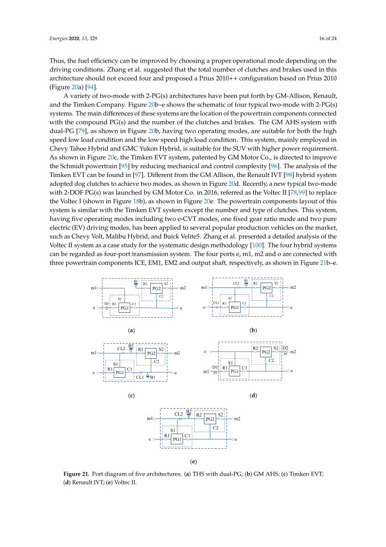
Energies 2020, 13, 329 16 of 24
Thus, the fuel efficiency can be improved by choosing a proper operational mode depending on thedriving conditions. Zhang et al. suggested that the total number of clutches and brakes used in thisarchitecture should not exceed four and proposed a Prius 2010++ configuration based on Prius 2010(Figure 20a) [94].
A variety of two-mode with 2-PG(s) architectures have been put forth by GM-Allison, Renault,and the Timken Company. Figure 20b–e shows the schematic of four typical two-mode with 2-PG(s)systems. The main differences of these systems are the location of the powertrain components connectedwith the compound PG(s) and the number of the clutches and brakes. The GM AHS system withdual-PG [79], as shown in Figure 20b, having two operating modes, are suitable for both the highspeed low load condition and the low speed high load condition. This system, mainly employed inChevy Tahoe Hybrid and GMC Yukon Hybrid, is suitable for the SUV with higher power requirement.As shown in Figure 20c, the Timken EVT system, patented by GM Motor Co., is directed to improvethe Schmidt powertrain [95] by reducing mechanical and control complexity [96]. The analysis of theTimken EVT can be found in [97]. Different from the GM Allison, the Renault IVT [98] hybrid systemadopted dog clutches to achieve two modes, as shown in Figure 20d. Recently, a new typical two-modewith 2-DOF PG(s) was launched by GM Motor Co. in 2016, referred as the Voltec II [78,99] to replacethe Voltec I (shown in Figure 18b), as shown in Figure 20e. The powertrain components layout of thissystem is similar with the Timken EVT system except the number and type of clutches. This system,having five operating modes including two e-CVT modes, one fixed gear ratio mode and two pureelectric (EV) driving modes, has been applied to several popular production vehicles on the market,such as Chevy Volt, Malibu Hybrid, and Buick Velite5. Zhang et al. presented a detailed analysis of theVoltec II system as a case study for the systematic design methodology [100]. The four hybrid systemscan be regarded as four-port transmission system. The four ports e, m1, m2 and o are connected withthree powertrain components ICE, EM1, EM2 and output shaft, respectively, as shown in Figure 21b–e.
Energies 2020, 13, x FOR PEER REVIEW 16 of 24
requirement. As shown in Figure 20c, the Timken EVT system, patented by GM Motor Co., is directed to improve the Schmidt powertrain [95] by reducing mechanical and control complexity [96]. The analysis of the Timken EVT can be found in [97]. Different from the GM Allison, the Renault IVT [98] hybrid system adopted dog clutches to achieve two modes, as shown in Figure 20d. Recently, a new typical two-mode with 2-DOF PG(s) was launched by GM Motor Co. in 2016, referred as the Voltec II [78,99] to replace the Voltec I (shown in Figure 18b), as shown in Figure 20e. The powertrain components layout of this system is similar with the Timken EVT system except the number and type of clutches. This system, having five operating modes including two e-CVT modes, one fixed gear ratio mode and two pure electric (EV) driving modes, has been applied to several popular production vehicles on the market, such as Chevy Volt, Malibu Hybrid, and Buick Velite5. Zhang et al. presented a detailed analysis of the Voltec II system as a case study for the systematic design methodology [100]. The four hybrid systems can be regarded as four-port transmission system. The four ports e, m1, m2 and o are connected with three powertrain components ICE, EM1, EM2 and output shaft, respectively, as shown in Figure 21b–e.
(a) (b)
(c) (d)
(e)
Figure 21. Port diagram of five architectures: (a) THS with dual-PG; (b) GM AHS; (c) Timken EVT; (d) Renault IVT; (e) Voltec II.
Compared to type-a and type-b architectures, type-c architecture, especially for two-mode, having more operating modes by adding PG and clutches, can optimize the engine operation points and thus improve the fuel economy. However, the design complexity and cost increase accordingly.
3.2.4. Type-d: TEM-PHPS with Multiple Planetary Gears
Type-d architecture, a further improvement of the GM Allison, having multiple modes by employing more than two PG(s) referred to multi-PG(s), can provide more design flexibility and achieve strong output torque reinforcement and better fuel economy. However, the additional PG(s) will certainly increase system complexity and cost.
A variety of TEM-PHPS with multi-PG(s) can be found in patent documents and academic literatures. For example, GM has a series of patents on multi-PG(s) hybrid system designs. One of designs comes from US patent has four PG(s) and five clutches although the fourth PG is not strictly
PG1R1
S1C1
B1
TD
PG2R2 S2
C2
o
m1
e
m2
PG1R1
S1C1
B1
CL1
PG2R2 S2CL2
C2
o
m1
e
m2
o
m1
e
m2
B1PG1
R1S1
C1
B2PG2
R2 S2CL2
C2
CL1
D1o
e
m1
m2
PG1R1
S1C1
PG2R2 S2
C2
D2
o
m1
e
m2
PG1R1
S1C1
B2PG2
R2 S2CL2
C2
Figure 21. Port diagram of five architectures: (a) THS with dual-PG; (b) GM AHS; (c) Timken EVT;(d) Renault IVT; (e) Voltec II.

Energies 2020, 13, 329 17 of 24
Compared to type-a and type-b architectures, type-c architecture, especially for two-mode,having more operating modes by adding PG and clutches, can optimize the engine operation pointsand thus improve the fuel economy. However, the design complexity and cost increase accordingly.
3.2.4. Type-d: TEM-PHPS with Multiple Planetary Gears
Type-d architecture, a further improvement of the GM Allison, having multiple modes byemploying more than two PG(s) referred to multi-PG(s), can provide more design flexibility andachieve strong output torque reinforcement and better fuel economy. However, the additional PG(s)will certainly increase system complexity and cost.
A variety of TEM-PHPS with multi-PG(s) can be found in patent documents and academicliteratures. For example, GM has a series of patents on multi-PG(s) hybrid system designs. One ofdesigns comes from US patent has four PG(s) and five clutches although the fourth PG is not strictlynecessary [101], while other designs mainly focus on triple-PG(s) architectures. A patent published in1999 [102], introducing a triple-PG configuration, has a low utilization rate. In addition, the patents,published by the engineer of GM in 2007 [103], introducing fifteen kinds of triple-PG architecture,almost all possible architectures. Recently, Hendrickson et al. [104] and Meisel [105] introduced a new2MT + 4FG configuration with three PG(s), which is known as 2MT70 and used in the Saturn VueGreen Line vehicle. However, it is usually considered as dual-PG architecture. In addition, an IVTsystem with four-PG(s) is developed by Renault, which differs from the GM designs that dog clutchesare employed to realize two modes [98].
Two typical triple-PG architectures are analyzed in this section, as shown in Figure 22.The two-mode EVT referred to AHS with triple-PG(s) [95], as shown in Figure 22a, is successfullyutilized in transit buses and is appropriate for many other heavy-duty stop-and-go applications [80].This system achieves two modes of high speed and low speed via two clutches. A new triple-PG(s)architecture introduced by Tim M. Grewe, a modified design of AHS by adding two clutches CL2 andB2, is specifically designed for full-size SUVs and other personal trucks, as shown in Figure 22b [80].The relevant patent is awarded to M. Schmidt in 2005 used for personal trucks [106]. This architecture isknown as the two-mode hybrid (Allison Hybrid System-2 (AHS2)). The only slight difference betweenthe design shown in the Figure 22b and the schematic of the patent is the location of the additionalclutch CL2 that is linked to the carrier of the second PG in the latter. In both the cases, the engagementof the CL2 can lock the first two planetary gears, and all components will have the same angular speed.Compared to the AHS, two additional clutches in the AHS2 architecture are added to produce fourfixed speed ratio (FG) modes. The analysis of the new architecture by Kaehler et al. shows that it issuitable for personal trucks since it can achieve maximum fuel economy at a reasonable cost [107].In addition, Tamai G et al. described how fuel economy functionality was blended with full-sizetruck utility functions [108]. The AHS2 architecture was applied to the new version of Yukon andTahoe vehicles.
Energies 2020, 13, x FOR PEER REVIEW 17 of 24
necessary [101], while other designs mainly focus on triple-PG(s) architectures. A patent published in 1999 [102], introducing a triple-PG configuration, has a low utilization rate. In addition, the patents, published by the engineer of GM in 2007 [103], introducing fifteen kinds of triple-PG architecture, almost all possible architectures. Recently, Hendrickson et al. [104] and Meisel [105] introduced a new 2MT + 4FG configuration with three PG(s), which is known as 2MT70 and used in the Saturn Vue Green Line vehicle. However, it is usually considered as dual-PG architecture. In addition, an IVT system with four-PG(s) is developed by Renault, which differs from the GM designs that dog clutches are employed to realize two modes [98].
Two typical triple-PG architectures are analyzed in this section, as shown in Figure 22. The two-mode EVT referred to AHS with triple-PG(s) [95], as shown in Figure 22a, is successfully utilized in transit buses and is appropriate for many other heavy-duty stop-and-go applications [80]. This system achieves two modes of high speed and low speed via two clutches. A new triple-PG(s) architecture introduced by Tim M. Grewe, a modified design of AHS by adding two clutches CL2 and B2, is specifically designed for full-size SUVs and other personal trucks, as shown in Figure 22b [80]. The relevant patent is awarded to M. Schmidt in 2005 used for personal trucks [106]. This architecture is known as the two-mode hybrid (Allison Hybrid System-2 (AHS2)). The only slight difference between the design shown in the Figure 22b and the schematic of the patent is the location of the additional clutch CL2 that is linked to the carrier of the second PG in the latter. In both the cases, the engagement of the CL2 can lock the first two planetary gears, and all components will have the same angular speed. Compared to the AHS, two additional clutches in the AHS2 architecture are added to produce four fixed speed ratio (FG) modes. The analysis of the new architecture by Kaehler et al. shows that it is suitable for personal trucks since it can achieve maximum fuel economy at a reasonable cost [107]. In addition, Tamai G et al. described how fuel economy functionality was blended with full-size truck utility functions [108]. The AHS2 architecture was applied to the new version of Yukon and Tahoe vehicles.
(a) (b)
Figure 22. Type-d architecture: (a) GM AHS; (b) GM AHS2.
The AHS and AHS2 architecture can be considered as four-port system. The four ports e, m1, m2 and o are connected with four powertrain components ICE, EM1, EM2 and output shaft, respectively, as shown in Table 5. The AHS2 system has the same EVT modes with the AHS, and the power flow of the main drive modes of the AHS2 are listed in Table 5. This provides the designer with insight into a method to show the power flow of the system, which is intuitive and easy to understand.
B1
PG1R1
C1
S1
PG3
S3
C3R3
ICE PG2S2
C2
R2
EM1
CL1O
EM2
B1
PG1R1
C1
S1
PG3S3
C3R3
ICE PG2S2
C2
R2
EM1
CL2
B2CL1
O
EM2
Figure 22. Type-d architecture: (a) GM AHS; (b) GM AHS2.
The AHS and AHS2 architecture can be considered as four-port system. The four ports e, m1,m2 and o are connected with four powertrain components ICE, EM1, EM2 and output shaft, respectively,as shown in Table 5. The AHS2 system has the same EVT modes with the AHS, and the power flow of
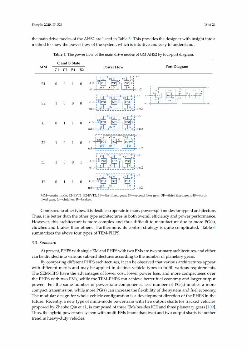
Energies 2020, 13, 329 18 of 24
the main drive modes of the AHS2 are listed in Table 5. This provides the designer with insight into amethod to show the power flow of the system, which is intuitive and easy to understand.
Table 5. The power flow of the main drive modes of GM AHS2 by four-port diagram.
MMC and B State
Power Flow Port DiagramC1 C2 B1 B2
E1 0 0 1 0
Energies 2020, 13, x FOR PEER REVIEW 18 of 24
Table 5. The power flow of the main drive modes of GM AHS2 by four-port diagram.
MM C and B State
Power Flow Port Diagram C1 C2 B1 B2
E1 0 0 1 0
E2 1 0 0 0
1F 0 1 1 0
2F 1 0 1 0
3F 1 0 0 1
4F 0 1 1 0
MM—main mode; E1-EVT1; E2-EVT2; 1F—first fixed gear; 2F—second fixes gear; 3F—third fixed gear; 4F—forth fixed gear; C—clutches; B—brakes.
Compared to other types, it is flexible to operate in many power-split modes for type-d architecture. Thus, it is better than the other type architectures in both overall efficiency and power performance. However, this architecture is more complex and thus difficult to manufacture due to more PG(s), clutches and brakes than others. Furthermore, its control strategy is quite complicated. Table 6 summarizes the above four types of TEM-PHPS.
3.3. Summary
At present, PHPS with single EM and PHPS with two EMs are two primary architectures, and either can be divided into various sub-architectures according to the number of planetary gears.
Table 6. The Comparison of four types of two EMs planetary hybrid powertrain system (TEM-PHPS).
Arc. PG. OT AC OM Advantages Disadvantages Lit.
Type-a 1 - 0 S simplest and low-cost
only one mode worst performance
[82]
1 - 3 M four operating modes better fuel economy
lower performance [83]
Type-b 1 FG 1 M larger output torque motor efficiency drops at
high speed [26]
Type-c
2 - 1 S better power and off-road
than THS still has only one operating
mode [89]
2 - 2/3/4 M enable more operating
modes higher fuel economy
more complex and costs [79,96,98,
99]
Type-d M - 2/4 M better overall efficiency
power performance most complex and
complicated control [80,95]
Arc.—architectures; PG.—PG number; OT—other transmission; AC—additional clutches; OM—operating mode; S—single; M—multiple; Ms-G—multiple shaft gears; Lit.—Literature.
B1
PG1R1
C1
S1
PG3S3
C3R3
PG2S2
C2
R2CL2
B2CL1
o
m1
e
m2
C1
PG1
m1
R1C2
e
o
m2
PG2 PG3S1
C3
R2
S2
S3
R3
m2
C1
PG1
m1
R1C2
e
o
PG2 PG3S1
C3
R2
S2
S3
R3
C1
PG1
m1
R1C2
e
o
m2
PG2 PG3S1
C3
R2
S2
S3
R3
C1
PG1
m1
R1C2
e
o
m2
PG2 PG3S1
C3
R2
S2
S3
R3
C1
PG1
m1
R1C2
e
o
m2
PG2 PG3S1
C3
R2
S2
S3
R3
E2 1 0 0 0
Energies 2020, 13, x FOR PEER REVIEW 18 of 24
Table 5. The power flow of the main drive modes of GM AHS2 by four-port diagram.
MM C and B State
Power Flow Port Diagram C1 C2 B1 B2
E1 0 0 1 0
E2 1 0 0 0
1F 0 1 1 0
2F 1 0 1 0
3F 1 0 0 1
4F 0 1 1 0
MM—main mode; E1-EVT1; E2-EVT2; 1F—first fixed gear; 2F—second fixes gear; 3F—third fixed gear; 4F—forth fixed gear; C—clutches; B—brakes.
Compared to other types, it is flexible to operate in many power-split modes for type-d architecture. Thus, it is better than the other type architectures in both overall efficiency and power performance. However, this architecture is more complex and thus difficult to manufacture due to more PG(s), clutches and brakes than others. Furthermore, its control strategy is quite complicated. Table 6 summarizes the above four types of TEM-PHPS.
3.3. Summary
At present, PHPS with single EM and PHPS with two EMs are two primary architectures, and either can be divided into various sub-architectures according to the number of planetary gears.
Table 6. The Comparison of four types of two EMs planetary hybrid powertrain system (TEM-PHPS).
Arc. PG. OT AC OM Advantages Disadvantages Lit.
Type-a 1 - 0 S simplest and low-cost
only one mode worst performance
[82]
1 - 3 M four operating modes better fuel economy
lower performance [83]
Type-b 1 FG 1 M larger output torque motor efficiency drops at
high speed [26]
Type-c
2 - 1 S better power and off-road
than THS still has only one operating
mode [89]
2 - 2/3/4 M enable more operating
modes higher fuel economy
more complex and costs [79,96,98,
99]
Type-d M - 2/4 M better overall efficiency
power performance most complex and
complicated control [80,95]
Arc.—architectures; PG.—PG number; OT—other transmission; AC—additional clutches; OM—operating mode; S—single; M—multiple; Ms-G—multiple shaft gears; Lit.—Literature.
B1
PG1R1
C1
S1
PG3S3
C3R3
PG2S2
C2
R2CL2
B2CL1
o
m1
e
m2
C1
PG1
m1
R1C2
e
o
m2
PG2 PG3S1
C3
R2
S2
S3
R3
m2
C1
PG1
m1
R1C2
e
o
PG2 PG3S1
C3
R2
S2
S3
R3
C1
PG1
m1
R1C2
e
o
m2
PG2 PG3S1
C3
R2
S2
S3
R3
C1
PG1
m1
R1C2
e
o
m2
PG2 PG3S1
C3
R2
S2
S3
R3
C1
PG1
m1
R1C2
e
o
m2
PG2 PG3S1
C3
R2
S2
S3
R3
1F 0 1 1 0
Energies 2020, 13, x FOR PEER REVIEW 18 of 24
Table 5. The power flow of the main drive modes of GM AHS2 by four-port diagram.
MM C and B State
Power Flow Port Diagram C1 C2 B1 B2
E1 0 0 1 0
E2 1 0 0 0
1F 0 1 1 0
2F 1 0 1 0
3F 1 0 0 1
4F 0 1 1 0
MM—main mode; E1-EVT1; E2-EVT2; 1F—first fixed gear; 2F—second fixes gear; 3F—third fixed gear; 4F—forth fixed gear; C—clutches; B—brakes.
Compared to other types, it is flexible to operate in many power-split modes for type-d architecture. Thus, it is better than the other type architectures in both overall efficiency and power performance. However, this architecture is more complex and thus difficult to manufacture due to more PG(s), clutches and brakes than others. Furthermore, its control strategy is quite complicated. Table 6 summarizes the above four types of TEM-PHPS.
3.3. Summary
At present, PHPS with single EM and PHPS with two EMs are two primary architectures, and either can be divided into various sub-architectures according to the number of planetary gears.
Table 6. The Comparison of four types of two EMs planetary hybrid powertrain system (TEM-PHPS).
Arc. PG. OT AC OM Advantages Disadvantages Lit.
Type-a 1 - 0 S simplest and low-cost
only one mode worst performance
[82]
1 - 3 M four operating modes better fuel economy
lower performance [83]
Type-b 1 FG 1 M larger output torque motor efficiency drops at
high speed [26]
Type-c
2 - 1 S better power and off-road
than THS still has only one operating
mode [89]
2 - 2/3/4 M enable more operating
modes higher fuel economy
more complex and costs [79,96,98,
99]
Type-d M - 2/4 M better overall efficiency
power performance most complex and
complicated control [80,95]
Arc.—architectures; PG.—PG number; OT—other transmission; AC—additional clutches; OM—operating mode; S—single; M—multiple; Ms-G—multiple shaft gears; Lit.—Literature.
B1
PG1R1
C1
S1
PG3S3
C3R3
PG2S2
C2
R2CL2
B2CL1
o
m1
e
m2
C1
PG1
m1
R1C2
e
o
m2
PG2 PG3S1
C3
R2
S2
S3
R3
m2
C1
PG1
m1
R1C2
e
o
PG2 PG3S1
C3
R2
S2
S3
R3
C1
PG1
m1
R1C2
e
o
m2
PG2 PG3S1
C3
R2
S2
S3
R3
C1
PG1
m1
R1C2
e
o
m2
PG2 PG3S1
C3
R2
S2
S3
R3
C1
PG1
m1
R1C2
e
o
m2
PG2 PG3S1
C3
R2
S2
S3
R3
2F 1 0 1 0
Energies 2020, 13, x FOR PEER REVIEW 18 of 24
Table 5. The power flow of the main drive modes of GM AHS2 by four-port diagram.
MM C and B State
Power Flow Port Diagram C1 C2 B1 B2
E1 0 0 1 0
E2 1 0 0 0
1F 0 1 1 0
2F 1 0 1 0
3F 1 0 0 1
4F 0 1 1 0
MM—main mode; E1-EVT1; E2-EVT2; 1F—first fixed gear; 2F—second fixes gear; 3F—third fixed gear; 4F—forth fixed gear; C—clutches; B—brakes.
Compared to other types, it is flexible to operate in many power-split modes for type-d architecture. Thus, it is better than the other type architectures in both overall efficiency and power performance. However, this architecture is more complex and thus difficult to manufacture due to more PG(s), clutches and brakes than others. Furthermore, its control strategy is quite complicated. Table 6 summarizes the above four types of TEM-PHPS.
3.3. Summary
At present, PHPS with single EM and PHPS with two EMs are two primary architectures, and either can be divided into various sub-architectures according to the number of planetary gears.
Table 6. The Comparison of four types of two EMs planetary hybrid powertrain system (TEM-PHPS).
Arc. PG. OT AC OM Advantages Disadvantages Lit.
Type-a 1 - 0 S simplest and low-cost
only one mode worst performance
[82]
1 - 3 M four operating modes better fuel economy
lower performance [83]
Type-b 1 FG 1 M larger output torque motor efficiency drops at
high speed [26]
Type-c
2 - 1 S better power and off-road
than THS still has only one operating
mode [89]
2 - 2/3/4 M enable more operating
modes higher fuel economy
more complex and costs [79,96,98,
99]
Type-d M - 2/4 M better overall efficiency
power performance most complex and
complicated control [80,95]
Arc.—architectures; PG.—PG number; OT—other transmission; AC—additional clutches; OM—operating mode; S—single; M—multiple; Ms-G—multiple shaft gears; Lit.—Literature.
B1
PG1R1
C1
S1
PG3S3
C3R3
PG2S2
C2
R2CL2
B2CL1
o
m1
e
m2
C1
PG1
m1
R1C2
e
o
m2
PG2 PG3S1
C3
R2
S2
S3
R3
m2
C1
PG1
m1
R1C2
e
o
PG2 PG3S1
C3
R2
S2
S3
R3
C1
PG1
m1
R1C2
e
o
m2
PG2 PG3S1
C3
R2
S2
S3
R3
C1
PG1
m1
R1C2
e
o
m2
PG2 PG3S1
C3
R2
S2
S3
R3
C1
PG1
m1
R1C2
e
o
m2
PG2 PG3S1
C3
R2
S2
S3
R3
3F 1 0 0 1
Energies 2020, 13, x FOR PEER REVIEW 18 of 24
Table 5. The power flow of the main drive modes of GM AHS2 by four-port diagram.
MM C and B State
Power Flow Port Diagram C1 C2 B1 B2
E1 0 0 1 0
E2 1 0 0 0
1F 0 1 1 0
2F 1 0 1 0
3F 1 0 0 1
4F 0 1 1 0
MM—main mode; E1-EVT1; E2-EVT2; 1F—first fixed gear; 2F—second fixes gear; 3F—third fixed gear; 4F—forth fixed gear; C—clutches; B—brakes.
Compared to other types, it is flexible to operate in many power-split modes for type-d architecture. Thus, it is better than the other type architectures in both overall efficiency and power performance. However, this architecture is more complex and thus difficult to manufacture due to more PG(s), clutches and brakes than others. Furthermore, its control strategy is quite complicated. Table 6 summarizes the above four types of TEM-PHPS.
3.3. Summary
At present, PHPS with single EM and PHPS with two EMs are two primary architectures, and either can be divided into various sub-architectures according to the number of planetary gears.
Table 6. The Comparison of four types of two EMs planetary hybrid powertrain system (TEM-PHPS).
Arc. PG. OT AC OM Advantages Disadvantages Lit.
Type-a 1 - 0 S simplest and low-cost
only one mode worst performance
[82]
1 - 3 M four operating modes better fuel economy
lower performance [83]
Type-b 1 FG 1 M larger output torque motor efficiency drops at
high speed [26]
Type-c
2 - 1 S better power and off-road
than THS still has only one operating
mode [89]
2 - 2/3/4 M enable more operating
modes higher fuel economy
more complex and costs [79,96,98,
99]
Type-d M - 2/4 M better overall efficiency
power performance most complex and
complicated control [80,95]
Arc.—architectures; PG.—PG number; OT—other transmission; AC—additional clutches; OM—operating mode; S—single; M—multiple; Ms-G—multiple shaft gears; Lit.—Literature.
B1
PG1R1
C1
S1
PG3S3
C3R3
PG2S2
C2
R2CL2
B2CL1
o
m1
e
m2
C1
PG1
m1
R1C2
e
o
m2
PG2 PG3S1
C3
R2
S2
S3
R3
m2
C1
PG1
m1
R1C2
e
o
PG2 PG3S1
C3
R2
S2
S3
R3
C1
PG1
m1
R1C2
e
o
m2
PG2 PG3S1
C3
R2
S2
S3
R3
C1
PG1
m1
R1C2
e
o
m2
PG2 PG3S1
C3
R2
S2
S3
R3
C1
PG1
m1
R1C2
e
o
m2
PG2 PG3S1
C3
R2
S2
S3
R3
4F 0 1 1 0
Energies 2020, 13, x FOR PEER REVIEW 18 of 24
Table 5. The power flow of the main drive modes of GM AHS2 by four-port diagram.
MM C and B State
Power Flow Port Diagram C1 C2 B1 B2
E1 0 0 1 0
E2 1 0 0 0
1F 0 1 1 0
2F 1 0 1 0
3F 1 0 0 1
4F 0 1 1 0
MM—main mode; E1-EVT1; E2-EVT2; 1F—first fixed gear; 2F—second fixes gear; 3F—third fixed gear; 4F—forth fixed gear; C—clutches; B—brakes.
Compared to other types, it is flexible to operate in many power-split modes for type-d architecture. Thus, it is better than the other type architectures in both overall efficiency and power performance. However, this architecture is more complex and thus difficult to manufacture due to more PG(s), clutches and brakes than others. Furthermore, its control strategy is quite complicated. Table 6 summarizes the above four types of TEM-PHPS.
3.3. Summary
At present, PHPS with single EM and PHPS with two EMs are two primary architectures, and either can be divided into various sub-architectures according to the number of planetary gears.
Table 6. The Comparison of four types of two EMs planetary hybrid powertrain system (TEM-PHPS).
Arc. PG. OT AC OM Advantages Disadvantages Lit.
Type-a 1 - 0 S simplest and low-cost
only one mode worst performance
[82]
1 - 3 M four operating modes better fuel economy
lower performance [83]
Type-b 1 FG 1 M larger output torque motor efficiency drops at
high speed [26]
Type-c
2 - 1 S better power and off-road
than THS still has only one operating
mode [89]
2 - 2/3/4 M enable more operating
modes higher fuel economy
more complex and costs [79,96,98,
99]
Type-d M - 2/4 M better overall efficiency
power performance most complex and
complicated control [80,95]
Arc.—architectures; PG.—PG number; OT—other transmission; AC—additional clutches; OM—operating mode; S—single; M—multiple; Ms-G—multiple shaft gears; Lit.—Literature.
B1
PG1R1
C1
S1
PG3S3
C3R3
PG2S2
C2
R2CL2
B2CL1
o
m1
e
m2
C1
PG1
m1
R1C2
e
o
m2
PG2 PG3S1
C3
R2
S2
S3
R3
m2
C1
PG1
m1
R1C2
e
o
PG2 PG3S1
C3
R2
S2
S3
R3
C1
PG1
m1
R1C2
e
o
m2
PG2 PG3S1
C3
R2
S2
S3
R3
C1
PG1
m1
R1C2
e
o
m2
PG2 PG3S1
C3
R2
S2
S3
R3
C1
PG1
m1
R1C2
e
o
m2
PG2 PG3S1
C3
R2
S2
S3
R3
MM—main mode; E1-EVT1; E2-EVT2; 1F—first fixed gear; 2F—second fixes gear; 3F—third fixed gear; 4F—forthfixed gear; C—clutches; B—brakes.
Compared to other types, it is flexible to operate in many power-split modes for type-d architecture.Thus, it is better than the other type architectures in both overall efficiency and power performance.However, this architecture is more complex and thus difficult to manufacture due to more PG(s),clutches and brakes than others. Furthermore, its control strategy is quite complicated. Table 6summarizes the above four types of TEM-PHPS.
3.3. Summary
At present, PHPS with single EM and PHPS with two EMs are two primary architectures, and eithercan be divided into various sub-architectures according to the number of planetary gears.
By comparing different PHPS architectures, it can be observed that various architectures appearwith different merits and may be applied in distinct vehicle types to fulfill various requirements.The SEM-HPS have the advantages of lower cost, lower power loss, and more compactness overthe PHPS with two EMs, while the TEM-PHPS can achieve better fuel economy and larger outputpower. For the same number of powertrain components, less number of PG(s) implies a morecompact transmission, while more PG(s) can increase the flexibility of the system and fuel economy.The modular design for whole vehicle configuration is a development direction of the PHPS in thefuture. Recently, a new type of multi-mode powertrain with two output shafts for tracked vehiclesproposed by Zhaobo Qin et al., is composed of three EMs besides ICE and three planetary gears [109].Thus, the hybrid powertrain system with multi-EMs (more than two) and two output shafts is anothertrend in heavy-duty vehicles.

Energies 2020, 13, 329 19 of 24
Table 6. The Comparison of four types of two EMs planetary hybrid powertrain system (TEM-PHPS).
Arc. PG. OT AC OM Advantages Disadvantages Lit.
Type-a1 - 0 S simplest and low-cost only one mode worst
performance [82]
1 - 3 M four operating modes betterfuel economy lower performance [83]
Type-b 1 FG 1 M larger output torque motor efficiencydrops at high speed [26]
Type-c2 - 1 S better power and off-road
than THSstill has only oneoperating mode [89]
2 - 2/3/4 M enable more operating modeshigher fuel economy
more complex andcosts [79,96,98,99]
Type-d M - 2/4 M better overall efficiencypower performance
most complex andcomplicated control [80,95]
Arc.—architectures; PG.—PG number; OT—other transmission; AC—additional clutches; OM—operating mode;S—single; M—multiple; Ms-G—multiple shaft gears; Lit.—Literature.
4. Conclusions
As concerns of environment deterioration and energy supply security keep increasing, PHPS hasbeen the mainstream on HEV market. The purpose of this review work is to classify and comparedifferent PHPS architectures and provide insights into architecture selection and design. A newclassification method for PHPS is systematically proposed to organize various HEV using planetarygears. As a critical step, two primary types of PHPS are identified to enable new classification suitablefor HEV using planetary gears. In addition, the representative PHPS architectures are reviewed andorganized in the new classification framework based on number of EM(s), number of planetary gearsand type of transmission. Furthermore, the port diagram of representative PHPS powertrains is given,and provides the designer with a method to show the power flow of the system, which is intuitive andeasy to understand. This review work, based on extensive references and industry products, not onlyprovides an up-to-date summary of PHPS powertrain architecture, but also presents relationship ofdifferent architectures in the new classification framework.
Author Contributions: Wrote the original draft, L.W.; Supervised this research work, Y.C.; Edited and proofreadthe manuscript, F.Z.; Collected the literatures, G.L. All authors have read and agreed to the published version ofthe manuscript.
Funding: This research was funded by National Natural Science Foundation of China (Grant No. 51905419) andNatural Science Basic Research Plan in Shaanxi Province of China (No. 2019JQ-503), the Fundamental ResearchFund for the Central Universities of China (grant No. 300102229514).
Conflicts of Interest: The authors declare no conflict of interest.
Abbreviations
HEVs Hybrid Electric VehiclesPHPS Planetary Hybrid Powertrain SystemEMs Electric MotorsICE Internal Combustion EngineCVT Continuously Variable Transmissionse-CVT electric Continuously Variable TransmissionsEVT Electric Variable TransmissionsPGs Planetary GearsDOF Degrees of FreedomSAE Society of Automotive EngineersSEM Single Electric Motor

Energies 2020, 13, 329 20 of 24
TEM Two Electric MotorCGST Clutchless Geared Smart TransmissionCHPTD Compact Hybrid Planetary Transmission DriveOWC One-Way ClutchS Sun gearR Ring gearC CarrierAT Automatic TransmissionAGT Automatic Geared TransmissionDCT Dual Clutch TransmissionHDT Hybrid Drive TrainHAST Hitachi Active Shift TransmissionAHS Allison Hybrid SystemFHS Ford Hybrid System
References
1. Schafer, A.; Victor, D.G. The Future Mobility of the World Population. Transp. Res. Part A Policy Pract. 2000,34, 171–205. [CrossRef]
2. Wee, J.-H. Contribution of Fuel Cell Systems to CO2 Emission Reduction in their Application Fields.Renew. Sustain. Energy Rev. 2010, 14, 735–744. [CrossRef]
3. Conti, J.; Holtberg, P.; Diefenderfer, J.; LaRose, A.; Turnure, J.T.; Westfall, L. International Energy Outlook 2016with Projections to 2040; Technical Report for USDOE; Energy Information Administration (EIA): Washington,DC, USA, 2016. [CrossRef]
4. Mohr, S.; Wang, J.; Ellem, G.; Ward, J.; Giurco, D. Projection of World Fossil Fuels by Country. Fuel 2015, 141,120–135. [CrossRef]
5. Ramachandran, S.; Stimming, U. Well to Wheel Analysis of Low Carbon Alternatives for Road Traffic.Energy Environ. Sci. 2015, 8, 3313–3324. [CrossRef]
6. Palencia, J.C.G.; Sakamaki, T.; Araki, M.; Shiga, S. Impact of Powertrain Electrification, Vehicle Size Reductionand Lightweight Materials Substitution on Energy Use, CO2 Emissions and Cost of a Passenger Light-DutyVehicle Fleet. Energy 2015, 93, 1489–1504. [CrossRef]
7. Global Comparison of Light-Duty Vehicle Fuel Economy/GHG Emissions Standards. Available online:https://theicct.org/sites/default/files/ICCT_PVStd_Aug2011_web.pdf (accessed on 1 August 2011).
8. Johnson, T.; Joshi, A. Review of Vehicle Engine Efficiency and Emissions. SAE Int. J. Engines 2018, 11,1307–1330. [CrossRef]
9. Huang, Y.; Surawski, N.C.; Organ, B.; Zhou, J.L.; Tang, O.H.; Chan, E.F. Fuel Consumption and EmissionsPerformance under Real Driving: Comparison between Hybrid and Conventional Vehicles. Sci. Total. Environ.2019, 659, 275–282. [CrossRef] [PubMed]
10. Zhou, Y.; Wang, M.; Hao, H.; Johnson, L.; Wang, H. Plug-In Electric Vehicle Market Penetration and Incentives:A Global Review. Mitig. Adapt. Strateg. Glob. Chang. 2015, 20, 777–795. [CrossRef]
11. Sabri, M.; Danapalasingam, K.; Rahmat, M. A Review on Hybrid Electric Vehicles Architecture and EnergyManagement Strategies. Renew. Sustain. Energy Rev. 2016, 53, 1433–1442. [CrossRef]
12. Mintz, M.; Han, J.; Burnham, A. Alternative and Renewable Gaseous Fuels to Improve Vehicle EnvironmentalPerformance. In Alternative Fuels and Advanced Vehicle Technologies for Improved Environmental Performance;Elsevier: Amsterdam, The Netherlands, 2014; pp. 90–116.
13. Sadeghinezhad, E.; Kazi, S.; Badarudin, A.; Oon, C.; Zubir, M.; Mehrali, M. A Comprehensive Review ofBio-Diesel as Alternative Fuel for Compression Ignition Engines. Renew. Sustain. Energy Rev. 2013, 28,410–424. [CrossRef]
14. Sutula, R.A.; Heitner, K.L.; Rogers, S.A.; Duong, T.Q.; Kirk, R.S.; Kumar, B.; Schonefeld, C. AdvancedAutomotive Technologies Energy Storage R&D Programs at the US Department of Energy-Recent Achievements andCurrent Status; SAE Technical Paper 0148-7191; SAE International: Warrendale, PA, USA, 2000.
15. Fang, H.-Y.; Wang, J.; Liu, K.-Q. Automotive Industry Energy Analysis and Energy-Saving TechnologyResearch. Automob. Parts 2009, 35, 42–45.

Energies 2020, 13, 329 21 of 24
16. Ehsani, M.; Gao, Y.; Longo, S.; Ebrahimi, K. Modern Electric, Hybrid Electric, and Fuel Cell Vehicles; CRC Press:Boca Raton, FL, USA, 2018.
17. Nikowitz, M. Advanced Hybrid and Electric Vehicles— System Optimization and Vehicle Integration; Springer:New York, NY, USA, 2016; pp. 1–3.
18. Veneri, O. Technologies and Applications for Smart Charging of Electric and Plug-In Hybrid Vehicles; Springer:New York, NY, USA, 2017.
19. Emadi, A.; Lee, Y.J.; Rajashekara, K. Power Electronics and Motor Drives in Electric, Hybrid Electric,and Plug-In Hybrid Electric Vehicles. IEEE Trans. Ind. Electron. 2008, 55, 2237–2245. [CrossRef]
20. Hawkins, T.R.; Gausen, O.M.; Strømman, A.H. Environmental Impacts of Hybrid and ElectricVehicles—A Review. Int. J. Life Cycle Assess. 2012, 17, 997–1014. [CrossRef]
21. Wu, G.; Zhang, X.; Dong, Z. Powertrain Architectures of Electrified Vehicles: Review, Classification andComparison. J. Frankl. Inst. 2015, 352, 425–448. [CrossRef]
22. Liu, Y.; Li, J.; Chen, Z.; Qin, D.; Zhang, Y. Research on a Multi-Objective Hierarchical Prediction EnergyManagement Strategy for Range Extended Fuel Cell Vehicles. J. Power Sources 2019, 429, 55–66. [CrossRef]
23. Chan, C.C. The State of the Art of Electric, Hybrid, and Fuel Cell Vehicles. Proc. IEEE 2007, 95, 704–718.[CrossRef]
24. Hannan, M.; Azidin, F.; Mohamed, A. Hybrid Electric Vehicles and Their Challenges: A Review. Renew. Sustain.Energy Rev. 2014, 29, 135–150. [CrossRef]
25. Zhang, F.; Hu, X.; Langari, R.; Cao, D. Energy Management Strategies of Connected HEVs and PHEVs:RECENT Progress and Outlook. Prog. Energy Combust. Sci. 2019, 73, 235–256. [CrossRef]
26. Miller, J.M. Hybrid Electric Vehicle Propulsion System Architectures of the e-CVT type. IEEE Trans. PowerElectron. 2006, 21, 756–767. [CrossRef]
27. Emadi, A.; Rajashekara, K.; Williamson, S.S.; Lukic, S.M. Topological Overview of Hybrid Electric and FuelCell Vehicular Power System Architectures and Configurations. IEEE Trans. Veh. Technol. 2005, 54, 763–770.[CrossRef]
28. Ehsani, M.; Gao, Y.; Miller, J.M. Hybrid Electric Vehicles: Architecture and Motor Drives. Proc. IEEE 2007, 95,719–728. [CrossRef]
29. Miller, J.M. Propulsion Systems for Hybrid Vehicles, 2nd ed.; The Institution of Engineering and Technology:London, UK, 2010; p. 67.
30. Brendan, C. Comparative Analysis of Single and Combined Hybrid Electrically Variable TransmissionOperating Mode. SAE Trans. 2005, 1265–1275. [CrossRef]
31. Bertoluzzo, M.; Bolognesi, P.; Buja, G. Role and Technology of the Power Split Apparatus in Hybrid ElectricVehicles. IEEE Trans. Control. Syst. Technol. 2007. [CrossRef]
32. Wang, Y.; Cheng, M.; KT, C. Review of Electronic-Continuously Variable Transmission Propulsion System forFull Hybrid Electric Vehicles. J. Asian Electr. Veh. 2009, 7, 1297–1302. [CrossRef]
33. Wei, D.; Fuwu, Y.; Changqing, D. Powertrain Control Strategies Overview for Hybrid Electric Vehicles.In Proceedings of the 2010 Asia-Pacific Power and Energy Engineering Conference, Chengdu, China, 28–31March 2010.
34. Dong, J.; Dong, Z.; Crawford, C. Review of Continuously Variable Transmission Powertrain System forHybrid Electric Vehicles. In Proceedings of the ASME 2011 International Mechanical Engineering Congress& Exposition, Denver, CO, USA, 11–17 November 2011; ASME: New York, NY, USA, 2012.
35. Cheng, Y.; Cheng, M. EVT and E-CVT for Full Hybrid Electric Vehicles. Encycl. Automot. Eng. 2014, 1–9.[CrossRef]
36. Yang, Y.; Ali, K.A.; Roeleveld, J.; Emadi, A. State-Of-The-Art Electrified Powertrains-Hybrid, Plug-In,and Electric Vehicles. Int. J. Powertrains 2016, 5, 1. [CrossRef]
37. Hu, J.; Mei, B.; Peng, H.; Jiang, X. Optimization Design and Analysis for a Single Motor Hybrid PowertrainConfiguration with Dual Planetary Gears. Appl. Sci. 2019, 9, 707. [CrossRef]
38. Kim, S.J.; Kim, K.-S.; Kum, D. Feasibility Assessment and Design Optimization of a Clutchless MultimodeParallel Hybrid Electric Powertrain. IEEE/ASME Trans. Mechatron. 2016, 21, 774–786. [CrossRef]
39. Yang, Y.; Hu, X.; Pei, H.; Peng, Z. Comparison of Power-Split and Parallel Hybrid Powertrain Architectureswith a Single Electric Machine: Dynamic Programming Approach. Appl. Energy 2016, 168, 683–690.[CrossRef]

Energies 2020, 13, 329 22 of 24
40. Ngo, H.-T.; Yan, H.-S. Novel Configurations for Hybrid Transmissions Using a Simple Planetary Gear Train.J. Mech. Robot. 2016, 8, 021020. [CrossRef]
41. Yoon, Y.-S.; Kim, S.; Kim, K.-S. Conceptual Design of Economic Hybrid Vehicle System Using ClutchlessGeared Smart Transmission. Int. J. Automot. Technol. 2013, 14, 779–784. [CrossRef]
42. Zhu, F.; Chen, L.; Yin, C. Design and Analysis of a Novel Multimode Transmission for a HEV Using a SingleElectric Machine. IEEE Trans. Veh. Technol. 2013, 62, 1097–1110. [CrossRef]
43. Zhang, Y.; Lin, H.; Zhang, B.; Mi, C. Performance Modeling and Optimization of a Novel Multi-Mode HybridPowertrain. J. Mech. Des. 2006, 128, 79–89. [CrossRef]
44. Tsai, L.-W. Design of a Paper Regulating Gearbox for Parallel Hybrid Electric Vehicles. Available online:https://drum.lib.umd.edu/bitstream/handle/1903/5746/TR_96-16.pdf?sequence=1&isAllowed=y (accessed on29 February 1996).
45. Wen, S. New Energy Vehicles and Intelligent Technologies; Southeast University Press: Nanjing, China, 2017.46. Szumanowski, A. Hybrid Electric Vehicle Drives Design Edition Based on Urban Buses; Beijing Institute of
Technology Press: Beijing, China, 2007.47. Zhao, H. Hybrid Electric Vehicle Technology; China Machine Press: Beijing, China, 2012.48. Yao, M.; Qin, D.; Zhou, X.; Zhan, S.; Zeng, Y. Integrated Optimal Control of Transmission Ratio and Power
Split Ratio for a CVT-Based Plug-In Hybrid Electric Vehicle. Mech. Mach. Theory 2019, 136, 52–71. [CrossRef]49. Mayet, C.; Welles, J.; Bouscayrol, A.; Hofman, T.; Lemaire-Semail, B. Influence of a CVT on the Fuel
Consumption of a Parallel Medium-Duty Electric Hybrid Truck. Math. Comput. Simul. 2018, 158, 120–129.[CrossRef]
50. Miller, J.M.; Everett, M. An Assessment of Ultra-Capacitors as the Power Cache in TOYOTA THS-II,GM-Allision AHS-2 and Ford FHS Hybrid Propulsion Systems. In Proceedings of the Twentieth Annual IEEEApplied Power Electronics Conference and Exposition, Austin, TX, USA, 6–10 March 2005; IEEE: Piscataway,NJ, USA, 2005.
51. Tinelli, V.; Galvagno, E.; Velardocchia, M. Dynamic Analysis and Control of a Dual Mode Electrically VariableTransmission. In Advances in Mechanism and Machine Science; Springer: New York, NY, USA, 2019; Volume 73,pp. 3731–3740.
52. Reif, K.; Noreikat, K.E.; Borgeest, K. Kraftfahrzeug-Hybridantriebe: Grundlagen, Komponenten, Systeme,Anwendungen; Springer Fachmedien Wiesbaden: Wiesbaden, Germany, 2012.
53. Gao, Y.; Ehsani, M.; Miller, J.M. Hybrid Electric Vehicle: Overview and State of the Art. In Proceedings of theIEEE International Symposium on Industrial Electronics, Dubrovnik, Croatia, 20–23 June 2005.
54. Wan, Y.; Liu, T. Scheme Selection Theory and Optimization of Planetary Gearbox; National Defense Industry Press:Beijing, China, 1997.
55. Tsai, L.W.; Schultz, G.; Higuchi, N. A Novel Parallel Hybrid Transmission. J. Mech. Des. 2001, 123, 161–168.[CrossRef]
56. A Motor-Integrated Parallel Hybrid Transmission. Available online: https://escholarship.org/uc/item/
1nm1408v (accessed on 2 October 2002).57. Tsai, L.-W.; Schultz, G.A. Transmission Gearbox for Parallel Hybrid Electric Vehicles. U.S. Patent 6592484B1,
15 July 2003.58. Tsai, L.-W.; Schultz, G. Motor integrated parallel hybrid transmission. U.S. Patent 6,837,816, 4 January 2005.59. Bachmann, M. Hybrid Drive Train of a Motor Vehicle. U.S. Patent 2010/0009805, 14 January 2010.60. Chachra, D.; Seth, B. Hybrid Transmission System. U.S. Patent 7753816B2, 13 July 2010.61. Turnbull, P.F.; Conlon, B.M.; Holmes, A.G.; Swales, S.H. Electrically Variable Transmission. U.S. Patent
8585520, 19 November 2013.62. Newcomb, T.; Spurr, R. Friction Materials in MJ Neale. In Tribology Handbook; Butterworths: London, UK,
1996.63. Zagrodzki, P. Analysis of Thermomechanical Phenomena in Multidisc Clutches and Brakes. Wear 1990, 140,
291–308. [CrossRef]64. Heijden, A.V.D.; Serrarens, A.; Camlibel, M.; Nijmeijer, H. Hybrid Optimal Control of Dry Clutch Engagement.
Int. J. Control. 2007, 80, 1717–1728. [CrossRef]65. Teshima, T.; Uezono, S.; Izumi, S.; Sakamoto, H.; Ibamoto, M.; Heath, R. Experimental Manufactured Car of
Hybrid System (HAST); JSAE Paper No. 20065638; JSAE: Tokyo, Japan, 2006.

Energies 2020, 13, 329 23 of 24
66. Yoon, Y.-S.; Kim, K.S.; Kim, S.J. Clutchless Geared Smart Transmission; SAE Technical Paper 2011-01-2031;SAE International: Warrendale, PA, USA, 2011. [CrossRef]
67. Kim, S.J.; Song, C.; Km, S.K.; Yoon, Y.-S. Analysis of the shifting behavior of a novel clutchless geared smarttransmission. Int. J. Automot. Technol. 2014, 15, 125–134. [CrossRef]
68. Son, H.; Yoon, Yo.; Kim, S.J.; Song, C.; Kim, K. Economic Hybrid Transmission System Using ClutchlessGeared Manual Transmission. 2015. Available online: http://www.evs28.org/event_file/event_file/1/pfile/
EVS28_Full%20papers_4.pdf (accessed on 3 May 2015).69. Kim, S.J.; Yoon, Y.-S.; Kim, S.; Kim, K.-S. Fuel Economy Assessment of Novel Multi-Mode Parallel Hybrid
Electric Vehicle. Int. J. Automot. Technol. 2015, 16, 501–512. [CrossRef]70. Szumanowski, A.; Piórkowski, P.; Hajduga, A.; Ngueyen, K. The Approach to Proper Control of Hybrid
Drive. In Proceedings of the World Electric Vehicle Symposium and Exposition (EVS) EVS17, Montreal, QC,Canada, 2000.
71. Szumanowski, A. Hybrid Electric Vehicle Drives Design; Publishing and Printing House of the Institute forSustainable Technologies-NRI: Warsaw, Poland, 2006.
72. Liu, G.-R.; Zhou, M.-Z.; Wang, L.-L.; Wang, H. A Radar-Based Door Open Warning Technology for VehicleActive Safety. In Proceedings of the 2016 International Conference on Information System and ArtificialIntelligence (ISAI), Hongkong, China, 24–26 June 2016; IEEE: Piscataway, NJ, USA, 2017.
73. Oba, H.; Yamanaka, A.; Katsuta, H.; Kamichi, K. Development of a Hybrid Powertrain System Using CVT in aMinivan; SAE Technical Paper 0148-7191; SAE International: Warrendale, PA, USA, 2002.
74. Tsai, L.W.; Schultz, G. A Motor-Integrated Parallel Hybrid Transmission. J. Mech. Des. Sep. 2002, 126, 889–894.[CrossRef]
75. Shin, S.; Oh, J.; Kim, J.; Hong, S. A Method of Gear-Shift in Parallel Hybrid Electric Vehicle Using Motor Control;SAE Technical Paper 0148-7191; SAE International: Warrendale, PA, USA, 2010.
76. Kulkarni, M.; Shim, T.; Zhang, Y. Shift Dynamics and Control of Dual-Clutch Transmissions.Mech. Mach. Theory 2007, 42, 168–182. [CrossRef]
77. Gelb, G.H.; Richardson, N.; Wang, T.; Berman, B. An Electromechanical Transmission for Hybrid VehiclePower Trains–Design and Dynamometer Testing. SAE Trans. 1971, 80, 915–929.
78. Duhon, A.N.; Sevel, K.S.; Tarnowsky, S.A.; Savagian, P.J. Chevrolet Volt Electric Utilization. SAE Int. J.Altern. Powertrains 2015, 4, 269–276. [CrossRef]
79. Holmes, A.G.; Klemen, D.; Schmidt, M.R. Electrically Variable Transmission with Selective Input Split,Compound Split, Neutral and Reverse Modes. U.S. Patent 6527658B2, 4 March 2003.
80. Grewe, T.M.; Conlon, B.M.; Holmes, A.G. Defining the General Motors 2-Mode Hybrid Transmission. 2007.Available online: https://documents.epfl.ch/users/f/fr/froulet/www/Hybrid/HybridVehiclessession5-1.pdf(accessed on 16 April 2007).
81. Zhuang, W.; Zhang, X.; Ding, Y.; Wang, L.; Hu, X. Comparison of Multi-Mode Hybrid Powertrains withMultiple Planetary Gears. Appl. Energy 2016, 178, 624–632. [CrossRef]
82. Koide, T.; Matsui, H.; Nada, M. Hybrid Vehicle Drive System Having Two Motor/Generator Units and EngineStarting Means. U.S. Patent 5,934,395, 10 August 1999.
83. Miller, M.A.; Holmes, A.G.; Conlon, B.M.; Savagian, P. The GM “Voltec” 4ET50 Multi-Mode Electric Transaxle.SAE Int. J. Engines 2011, 4, 1102–1114. [CrossRef]
84. Zhang, X.; Peng, H.; Sun, J. Fellow, IEEE. Prius(+) and Volt(-)_ Configuration Analysis of Power-Split HybridVehicles With a Single Planetary Gear. IEEE Trans. Veh. Technol. 2012, 61, 3544–3552. [CrossRef]
85. Li, C.-T.; Zhang, X.; Peng, H. Design of Power-Split Hybrid Vehicles with a Single Planetary Gear.In Proceedings of the ASME 2012 5th Annual Dynamic Systems and Control Conference joint withthe JSME 2012 11th Motion and Vibration Conference, Fort Lauderdale, FL, USA, 17–19 October 2012.
86. Bayrak, A.E.; Ren, Y.; Papalambros, P.Y. Design of hybrid-electric vehicle architectures using auto-generationof feasible driving modes. In Proceedings of the ASME 2013 International Design Engineering TechnicalConferences and Computers and Information in Engineering Conference, Portland, OR, USA, 4–7 Augest2013; American Society of Mechanical Engineers: New York, NY, USA, 2013; p. V001T01A005.
87. Hata, H.; Matsui, H.; Ibaraki, R. Power Output Device, Hybrid Vehicle, and Method of Controlling Them.U.S. Patent 6886648B1, 3 May 2005.
88. Shen, S.; Veldpaus, F.E. Analysis and Control of a Flywheel Hybrid Vehicular Powertrain. Control. Syst.Technol. IEEE Trans. 2004, 12, 645–660. [CrossRef]

Energies 2020, 13, 329 24 of 24
89. Kikuchi, Y. Power Output Apparatus, Motor Vehicle Equipped with Power Output Apparatus, and ControlMethod of Power Output Apparatus. CN101248260B, 27 April 2011.
90. Kimura, A.; Ando, I.; Itagaki, K. Development of Hybrid System for SUV; SAE Technical Paper 0148-7191;SAE International: Warrendale, PA, USA, 2005; Available online: https://pdfs.semanticscholar.org/649c/
24f178eeb049bd69e978b4cddd3565cd1edf.pdf (accessed on 11 April 2005).91. Hermance, D.; Abe, S. Hybrid Vehicles Lessons Learned and Future Prospects; SAE Technical Paper; SAE
International: Warrendale, PA, USA, 2006.92. Muta, K.; Yamazaki, M.; Tokieda, J. Development of New-Generation Hybrid System THS II-Drastic Improvement
of Power Performance and Fuel Economy; SAE Technical Paper 0148-7191; SAE International: Warrendale,PA, USA, 2004.
93. Kamichi, K.; Okasaka, K.; Tomatsuri, M.; Matsubara, T.; Kaya, Y.; Asada, H. Hybrid System Development fora High-Performance Rear Drive Vehicle; SAE Technical Paper 0148-7191; SAE International: Warrendale, PA,USA, 2006.
94. Zhang, X.; Peng, H.; Sun, J.; Li, S.E. Automated Modeling and Mode Screening for Exhaustive Search ofDouble-Planetary-Gear Power Split Hybrid Powertrains; ASME Paper No. DSCC2014-6028; ASME: New York,NY, USA, 2014. [CrossRef]
95. Schmidt, M.R. Two-Mode, Compound-Split Electro-Mechanical Vehicular Transmission. U.S. Patent 5,931,757,3 August 1999.
96. Holmes, A.G.; Schmidt, M.R. Hybrid Electric Powertrain Including a Two-Mode Electrically VariableTransmission. U.S. Patent 6,478,705, 12 November 2002.
97. Ai, X.; Mohr, T.; Anderson, S. An Electro-Mechanical Infinitely Variable Speed Transmission. SAE Trans.2004, 113, 96–110.
98. Villeneuve, A.M. Dual Mode Electric Infinitely Variable Transmission; SAE Technical Paper; SAE International:Warrendale, PA, USA, 2004.
99. Conlon, B.M.; Blohm, T.; Harpster, M.; Holmes, A.; Palardy, M.; Tarnowsky, S.; Zhou, L. The Next Generation“Voltec” Extended Range EV Propulsion System. SAE Int. J. Altern. Powertrains 2015, 4, 248–259. [CrossRef]
100. Zhang, X.; Li, S.E.; Peng, H.; Sun, J. Design of Multimode Power-Split Hybrid Vehicles—A Case Study on theVoltec Powertrain System. IEEE Trans. Veh. Technol. 2016, 65, 4790–4801. [CrossRef]
101. Schmidt, M.R. Four-Mode, Input-Split, Paralell, Hybrid Transmission. U.S. Patent 5,571,058, 5 November1996.
102. Schmidt, M.R. Electro-Mechanical Powertrain. U.S. Patent 5,935,035, 10 August 1999.103. Raghavan, M.; Bucknor, N.K.; Hendrickson, J.D. Electrically Variable Transmission Having Three Planetary
Gear Sets and Three Fixed Interconnections. WO2006073705A2, 13 July 2006.104. Hendrickson, J.; Holmes, A.; Freiman, D. General Motors front Wheel Drive Two-Mode Hybrid Transmission;
SAE Technical Paper 0148-7191; SAE International: Warrendale, PA, USA, 2009.105. Meisel, J. An Analytic Foundation for the Two-Mode Hybrid-Electric Powertrain with a Comparison to the Single-Mode
Toyota Prius THS-II Powertrain; SAE Technical Paper 0148-7191; SAE International: Warrendale, PA, USA, 2009.106. Schmidt, M.R.; Klemen, D.; Nitz, L.T.; Holmes, A.G. Two-Mode, Compound-Split, Hybrid Electro-Mechanical
Transmission Having Four Fixed Ratios. U.S. Patent 6953409B2, 11 October 2005.107. Kaehler, B.; Kersting, K.; Brouwer, M.; Christ, T. Design Criteria, Methods of Analysis, and Evaluation of
Power Split Transmissions Explained through a Two-Mode Hybrid Application. In Proceedings of theAachen Colloquium Automobile and Engine Technology, Aachen, Germany, 8–10 October 2007.
108. Tamai, G.; Reeves, S.; Grewe, T.H. Truck Utility & Functionality in the GM 2-Mode Hybrid. SAE Int. J. Engines2010, 3, 620–630.
109. Qin, Z.; Luo, Y.; Zhuang, W.; Pan, Z.; Li, K.; Peng, H. Simultaneous Optimization of Topology, Control andSize for Multi-Mode Hybrid Tracked Vehicles. Appl. Energy 2018, 212, 1627–1641. [CrossRef]
© 2020 by the authors. Licensee MDPI, Basel, Switzerland. This article is an open accessarticle distributed under the terms and conditions of the Creative Commons Attribution(CC BY) license (http://creativecommons.org/licenses/by/4.0/).