
REVERBERATION AND ECHO
19
REVERBERATION AND ECHO ARCH 426 LECTURE 7 Architectural Department Dr Hassan Hassoon ALDelfi
Transcript of REVERBERATION AND ECHO

REVERBERATION AND ECHOARCH 426
LECTURE 7
Architectural Department
Dr Hassan Hassoon ALDelfi

The INVERSE Square Law:
• A. Every time the physical distance between you and the sound source doubles in distance, the sound will be 6 dB lower (softer).
• B. The opposite holds true too. As the distance is cut in half, the sound will get louder by 6 dB
• Here is a very basic example: Start with a sound source that is
• ---------3-----------86dB
• -----------6-----------80dB
• -----------12----------74dB
• -----------24-----------68dB
• Thus less 6dB softer when distance doubles and louder when moves towards the source.
6/5/2018 Archetectural Acoustics ARCH 426 Dr Hassan Hassoon ALDelfi 2

Spl=20Log(p/pref)
6/5/2018 Archetectural Acoustics ARCH 426 Dr Hassan Hassoon ALDelfi 3
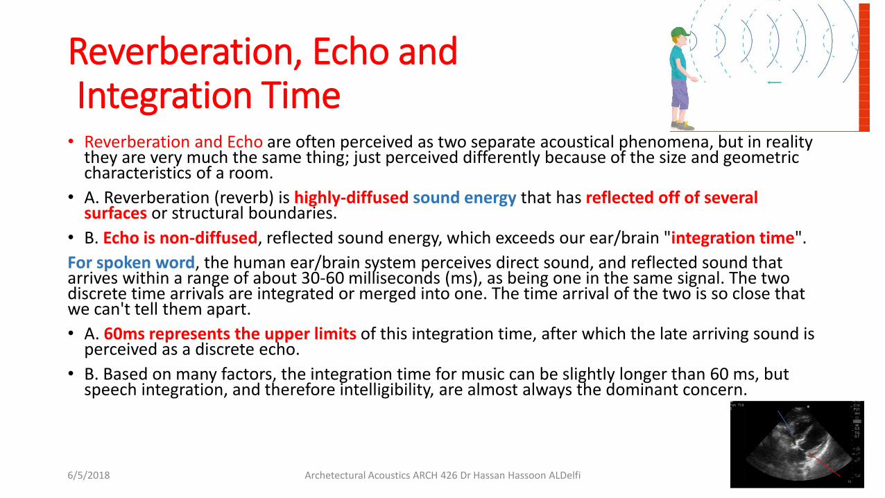
Reverberation, Echo andIntegration Time• Reverberation and Echo are often perceived as two separate acoustical phenomena, but in reality
they are very much the same thing; just perceived differently because of the size and geometric characteristics of a room.
• A. Reverberation (reverb) is highly-diffused sound energy that has reflected off of several surfaces or structural boundaries.
• B. Echo is non-diffused, reflected sound energy, which exceeds our ear/brain "integration time".
For spoken word, the human ear/brain system perceives direct sound, and reflected sound that arrives within a range of about 30-60 milliseconds (ms), as being one in the same signal. The two discrete time arrivals are integrated or merged into one. The time arrival of the two is so close that we can't tell them apart.
• A. 60ms represents the upper limits of this integration time, after which the late arriving sound is perceived as a discrete echo.
• B. Based on many factors, the integration time for music can be slightly longer than 60 ms, but speech integration, and therefore intelligibility, are almost always the dominant concern.
6/5/2018 Archetectural Acoustics ARCH 426 Dr Hassan Hassoon ALDelfi 4

The Room Modes:
• 1. A room with very simple geometry, i.e. a "cubed" rectangle, will almost always have the fewest number of resonant, modal frequencies. While this may sound like a good thing, it is not. The optimum goal is nearly the exact opposite. It is desirable for room modes to be reasonably-dense, and evenly spaced, throughout the LF wave-region of the frequency spectrum.
• a. A room with dense, evenly-space modal resonances will be perceived as having more "warmth", or a "warmer" sound. This is generally a good feature.
• b. These resonances must also be damped and contained in duration. This means the decay time of the various modal resonances must be well controlled so they properly match the venue's desired T60 range, and the audio material being performed or presented.
• 2. One other important goal is to minimize the excess strength of any specific modal frequency, or cluster of frequencies. When this is an issue, very targeted absorption or diffusion treatments may be required.
• 3. Room ratios are the primary controlling factor related to the density and spacing of the modes.
• It is not overly difficult to calculate the room modes of an empty, rectangular room, having a flat floor and ceiling. It is, however, extremely difficult to calculate room modes for a room with complex geometry
• Room dimensions typically start from the ceiling hard boundary.
• If we use the golden ratio then this will produce a room with dimensions based on the ceiling height, then to the width of the room and next the depth of the room.
• With an eight foot tall ceiling, based on the Golden ratio we would use 1: 1.62: 2.62, this would be a room with a ceiling height of 8 foot with a width of 13 feet and a depth of 21 feet!
6/5/2018 Archetectural Acoustics ARCH 426 Dr Hassan Hassoon ALDelfi 5

FLUTTER ECHO:
• Flutter echo:
• 1. In rectangular rooms, another significant area of concern relates to minimizing or eliminating audible echoes. Echo, sometimes called "flutter echo", occurs when sound bounces rapidly, back and forth, between hard, parallel surfaces.
• a. To minimize or eliminate discrete echo, any number of diffusive and/or absorptive finishes or treatments may be employed.
6/5/2018 Archetectural Acoustics ARCH 426 Dr Hassan Hassoon ALDelfi 6

Triangle AND OTHER SHAPES (2D floor plan)
• Triangle (2D floor plan) - A true triangle is not a common building shape, but it does present one nice feature; the side walls are about as far from parallel as possible. Flutter echo shouldn't be a problem, unless it occurs between the floor and ceiling.
• A. Warning: Triangular- and pyramid-shaped rooms present modal problems, much like cube-shaped rooms. This is especially true for equilateral, triangular enclosures.
• Quarter-round and half-round (2D floor plan) - In recent years these shapes have become popular for performing arts and house of worship venues.
• A. While these shapes can be quite good when considering sightlines, and a need to put the audience as close to the stage as possible, they can present acoustical challenges too.
• B. Any concaved, interior wall surface presents an acoustical paradox مفارقة.
• 1. If the concave surface is on the back wall of a stage, it may serve as an effective acoustical reflector, which may possibly enhance certain styles of musical performance.
• 2. If the back wall (opposite the stage) has a concave shape, it may not be a good acoustical element, and will probably need some specific treatment in order to minimize the negative effects (arc radii focusing) of the reflected energy bounding off the curved shape.
6/5/2018 Archetectural Acoustics ARCH 426 Dr Hassan Hassoon ALDelfi 7

Trapezoid (2D floor plan) AND PENTAGON
• Trapezoid (2D floor plan) - Like the quarter-round shape, the trapezoid room has one notable advantage: at least one set of walls is not parallel. This will help break up flutter echoes, and create more complex modal behavior in the LF wave region.
• A. The greatest disadvantage of the trapezoid shape is that the front and back walls are often either parallel, or one or both are built with a concave curvature. Both of these conditions will require further evaluation, and treatment, if not properly factored into the initial design.
Pentagon (2D floor plan) - The pentagon shape is favorite because it's the shape that offers a large seating area, good sight lines, and no major, parallel or curved walls.
• A. As nice as this shape may appear on first glance, there are still potential acoustic issues to be considered. These are based on:
• 2. The symmetry of the layout
• 3. The height and potential slope angle of the ceiling
• 4. The potential slope angle of the floor
• 5. The location of various key elements such as a stage, and the seating layout
6/5/2018 Archetectural Acoustics ARCH 426 Dr Hassan Hassoon ALDelfi 8

Hexagon (2D floor plan)
• Hexagon (2D floor plan) - More facetsجوانب is not necessarily better. The hexagon plan falls back into the rectangular group of shapes because it has multiple, parallel walls. All the same precautions must be taken related to flutter echoes and room modes.
• Heptagon (2D floor plan) - Much like the pentagon, a potentially good acoustical shape to consider. However, now construction costs start to climb, but with no real acoustical improvement.
• The heptagon سباعيshape also begins to more closely resemble a cylinder, which as noted above, can be problematic.
• Octagon - See hexagon and heptagon.
• Concave and convex planes - There is no question that architectural structures take on many other, more complex shapes than those outlined above. Therefore it is appropriate to summarize the relative merits of these two, plane curve shapes.
• Concave plane curves: Almost all concave planes are acoustically challenging, especially if they are finished with hard, reflective materials.
• 1. As noted earlier, concave surfaces can concentrate reflected sound energy into a fairly small area. The density of concentration, and the size of the focal point, are largely determined by the arc radius of the plane, and the overall size of the curved surface.
• 2. Focusing reflected sound is usually not desirable, and should be avoided in most situations. Yes, there are exceptions to this guideline, but they are rare, especially in multi-use facilities.
• B. Convex plane curves: Convex planes bring the exact opposite results, and are generally encouraged, where and whenever possible.
• 1. Convex planes are inherently diffusive, which is good. More often than not, convex planes result in improved acoustics and sound.
• 2. Faceted convex planes are less complementary, but still can be beneficial. The number of facets, and the arc radius of the curvature, will determine the relative benefits. More facets generally bring better results.
• 3. If a building's design is able to include two or more, mirror-image, convex planes, regardless of location, the need for additional diffusive or absorptive materials may be greatly minimized
6/5/2018 Archetectural Acoustics ARCH 426 Dr Hassan Hassoon ALDelfi 9

Symmetry
• Symmetry - If the purpose of a room is to support live performances or the presentation of other useful, audible information, it helps tremendously to design a symmetrical interior shell.
• A. One of the prime goals and challenges, for the sound system designer, is that of delivering even sound coverage to all seating areas.
• B. There are significant performance, cost, and aesthetic benefits achieved when a room is designed with mirror-image symmetry along the center line axis of the stage or platform.
• C. Later the importance of "time" will be further developed. But in the context of symmetry, it is important to note these points:
• 1. Good quality sound reinforcement requires careful analysis and implementation in the time domain. A sound system that is not properly "time-aligned" is analogous to a photograph that is out of focus.
• 2. Every major building element or feature, which introduces significant asymmetry to the floor plan, ceiling, and/or the audience seating area(s), can add cost and complexity to a room's sound system requirements.
• a. Asymmetrical sound propagation generally translates into time-domain challenges that must be resolved.
• b. Additional sound devices, labor, structural points, and aesthetic anomalies, can all become unexpected challenges brought on by the need to support an asymmetrical structure. Obviously, each of these adds cost and technical complexity to any sound system.
6/5/2018 Archetectural Acoustics ARCH 426 Dr Hassan Hassoon ALDelfi 10

Complex Interior Geometry and Asymmetrical Complexity• D. To reiterate. Within the guidelines for achieving a good acoustical
environment, complex interior geometry is a beneficial and much desired objective. Conversely, asymmetrical complexity is not an appropriate goal.
• 1. Example: The exterior of the Disney Concert Hall, in Los Angeles, is anything by symmetrical. However, upon closer inspection, you should notice that the performance area within the hall is very symmetrical, while also providing strikingly-complex structural geometry.
• E. Asymmetrical rooms can often result in unwanted or inconsistent acoustical areas or zones. If a room is designed with random, asymmetrical shapes and finishes, there is a good chance the acoustical results will be less than desirable.
• 1. Do note, there are some exceptions; times when specifying "zoned acoustics" is an appropriate and desirable goal. Application-specific, acoustic zones need to be carefully planned, and purpose-built.
6/5/2018 Archetectural Acoustics ARCH 426 Dr Hassan Hassoon ALDelfi 11

Ceiling Layout
• Ceiling Layout - Ceilings are a important element within the acoustical environment.
• A. Ceiling symmetry is just as another important as floor plan and wall symmetry.
• B. If a room is to have a single, interior ceiling slope, it's extremely helpful to have the highest point in the room located above the stage or platform, with the downward slope moving away from the stage.
• 1. The slope ratio should be in the range of 1:12 to 3:12. Anything having less slope is acoustically insignificant. A ratio that's too steep has its challenges too.
• 2. If there is a sloped or stepped floor planned, slant the floor and ceiling in opposite directions so the angles open widest above the stage.
• 3. Gradual, yet acoustically-significant slope changes are much preferred over dramatic changes.
• a. One challenging example can be seen in buildings that have a central clerestory, with a significantly lower ceiling structurebeyond.
• C. The A-framed, peak-ridge roof structure:
• 1. If a room design calls for an A-frame ridgeline, please, please, please DO NOT set the peak to run perpendicular to the centerline of the stage or platform.
• a. All kinds of presentation and propagation challenges are created when the peak ridge is turned sideways.
• b. A peak ridge, which runs parallel to the center line of the stage, is perfectly fine as long as the lowest point of the slope is equal to or greater than about 50% of the ceiling height at the peak. Read a shallow, not steep slope.
6/5/2018 Archetectural Acoustics ARCH 426 Dr Hassan Hassoon ALDelfi 12

Interior Elevations
• Elevations - Last, but far from least important are the room's overall interior elevations.
• A. If only one AA wish could to be granted, this designer would opt for more usable ceiling height. No other single, structural parameter makes the presentation of good sound, video and lighting more difficult, and expensive, than the lack of adequate vertical space; especially above a platform or stage.
• B. The larger the room, the more ceiling height that's needed.
• 1. If good results are desired and/or expected, a 20‘( 6m)ceiling should be considered a minimum guideline for a 5,000 ( 500m2)square foot room that is being designed for presentation or performance.
• 2. At 10,000 square feet 1000m2, the usable ceiling should be at least 30‘(10m). Here, the term usable means unobstructed.
• 3. Yes, of course, there are exceptions. Exceptions become workable solutions when greater expense and careful planning are allowed to coexist.
• C. Try to avoid adding any type of soffit اسفل البناء that runs directly above the stage and/or primary seating area(s). Even a small drop soffit, running above any key areas, can effectively define the lowest point for the entire room or platform.
• 1. If an important goal is good sound propagation, a mid-room soffit can easily translate into a more complex and expensive sound system.
• a. Example: If a room has a general ceiling height of 30', but has a soffit running through the middle of the room that finishes at 24' AFF, effectively, for all sound-related purposes, the room has a ceiling height of 24'. Without additional speakers being added, the HF rays may not be able to reach very far beyond the soffit.
• 2. If soffits can be pushed out to the far edges of a room, along the walls and away from the seating and staging area(s), this concern is significantly minimized.
6/5/2018 Archetectural Acoustics ARCH 426 Dr Hassan Hassoon ALDelfi 13

REVERBERATION AND ECHO
• REVERBERATION AND ECHO
• Reverberation and echo are often perceived as two separate acoustical phenomena, but in reality they are very much the same thing; just perceived differently because of the size and geometric characteristics of a room.
• A. Reverberation (reverb) is highly-diffused sound energy that has reflected off of several surfaces or structural boundaries.
• B. Echo is non-diffused, reflected sound energy, which exceeds our ear/brain "integration time".
• For spoken word, the human ear/brain system perceives direct sound, and reflected sound that arrives within a range of about 30-60 milliseconds (ms), as being one in the same signal. The two discrete time arrivals are integrated or merged into one. The time arrival of the two is so close that we can't tell them apart.
• A. 60ms represents the upper limits of this integration time, after which the late arriving sound is perceived as a discrete echo.
• B. Based on many factors, the integration time for music can be slightly longer than 60 ms, but speech integration, and therefore intelligibility, are almost always the dominant concern.
6/5/2018 Archetectural Acoustics ARCH 426 Dr Hassan Hassoon ALDelfi 14

REVERBERATION AND ECHO
Both reverb and echo are caused by sound bouncing off various room surfaces.
• A. Echo is more easily heard in small rooms, especially rooms with little or no geometric complexity.
• 1. A repetitive echo is sometimes called "flutter" echo because percussive sounds, like a hand clap, bounce rapidly between one or more sets of parallel surfaces, producing a "fluttery" sound.
• 2. Flutter echo is most obvious and problematic when two or more parallel walls are finished using hard, reflective materials.
• 3. Absorption and/or diffusion can be used to mitigateتخفيف problematic echoes.
• B. Reverberation is usually found in larger rooms.
• 1. A naturally-reverberant space will typically be voluminous. In most cases, the more cubic feet of air, the longer the reverb time.
• 2. Reverb time is measured in seconds, and represents the amount of time it takes a test stimulus signal to drop 60 dB below the initial SPL of the stimulus.
• 3. The unit of measurement is commonly referred to as T60. You may also see it as RT60, which today is somewhat dated terminology. The "T" is short for time, as in reverb time. The 60 represents 60 dB of SPL attenuation.
• 4. When fully stated, a measurement result might look like this: "The room has a T60 of 1.5 seconds", or "this room has a 1.3 second T60".
• a. Modern tools and techniques allow us to achieve similar results when using T30 and T20 measurements too.
6/5/2018 Archetectural Acoustics ARCH 426 Dr Hassan Hassoon ALDelfi 15

• 5. When a single T60 number is stated, it represents an average of two frequencies: 500 Hz and 1 kHz.
• C. In medium and large rooms, with simplistic geometry, it's common that both discrete echoes, and measurable reverberation, are present. When these conditions exist, it's common for the reverb to "mask" or cover up the echo.
• 1. This condition is typically found when the density and length of the reverb tail is equal to, or greater than, the intensity of the discrete echoes.
• 2. In such rooms, the misapplication of simple absorptive materials can reduce the reverb, but do little or nothing to mitigate the undesirable echoes that persist at a lower intensity.
• D. If given only one option, design and treat to eliminate echo. Reverberation is less problematic.
• 1. Both echo and reverb can be effectively managed by properly selecting and applying one or more of the acoustic tools mentioned above.
6/5/2018 Archetectural Acoustics ARCH 426 Dr Hassan Hassoon ALDelfi 16
Reverberant Time Slope (RTS):
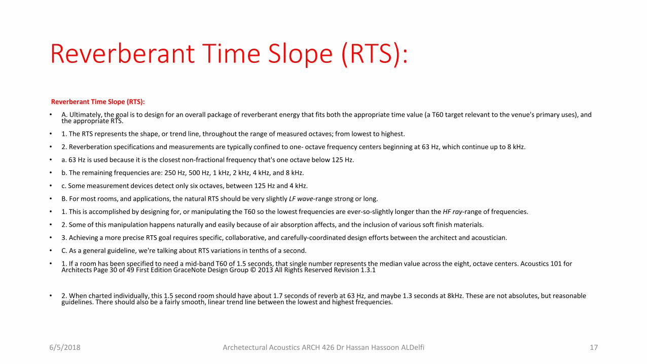
Reverberant Time Slope (RTS):
• A. Ultimately, the goal is to design for an overall package of reverberant energy that fits both the appropriate time value (a T60 target relevant to the venue's primary uses), and the appropriate RTS.
• 1. The RTS represents the shape, or trend line, throughout the range of measured octaves; from lowest to highest.
• 2. Reverberation specifications and measurements are typically confined to one- octave frequency centers beginning at 63 Hz, which continue up to 8 kHz.
• a. 63 Hz is used because it is the closest non-fractional frequency that's one octave below 125 Hz.
• b. The remaining frequencies are: 250 Hz, 500 Hz, 1 kHz, 2 kHz, 4 kHz, and 8 kHz.
• c. Some measurement devices detect only six octaves, between 125 Hz and 4 kHz.
• B. For most rooms, and applications, the natural RTS should be very slightly LF wave-range strong or long.
• 1. This is accomplished by designing for, or manipulating the T60 so the lowest frequencies are ever-so-slightly longer than the HF ray-range of frequencies.
• 2. Some of this manipulation happens naturally and easily because of air absorption affects, and the inclusion of various soft finish materials.
• 3. Achieving a more precise RTS goal requires specific, collaborative, and carefully-coordinated design efforts between the architect and acoustician.
• C. As a general guideline, we're talking about RTS variations in tenths of a second.
• 1. If a room has been specified to need a mid-band T60 of 1.5 seconds, that single number represents the median value across the eight, octave centers. Acoustics 101 for Architects Page 30 of 49 First Edition GraceNote Design Group © 2013 All Rights Reserved Revision 1.3.1
• 2. When charted individually, this 1.5 second room should have about 1.7 seconds of reverb at 63 Hz, and maybe 1.3 seconds at 8kHz. These are not absolutes, but reasonable guidelines. There should also be a fairly smooth, linear trend line between the lowest and highest frequencies.
6/5/2018 Archetectural Acoustics ARCH 426 Dr Hassan Hassoon ALDelfi 17

Direct to Reverberant Ratio (D/R)
Direct to Reverberant Ratio (D/R)
• A. Earlier, critical distance was described as the physical location in a room where direct sound energy and reverberant sound energy have equal SPL intensity. A close correlation exists between critical distance and the D/R values found throughout a venue.
• 1. If the D/R ratio is one-to-one (1:1), critical distance has been found.
• 2. As the D/R ratio improves (gets larger) sound clarity improves.
• 3. Depending on the venue, and the type of performance or presentation given, a D/R ratio of between 4:1 and 6:1, is a reasonable goal.
• a. In this instance, 4:1 means that the direct sound energy is 4 dB SPL louder than the reverberant energy
• B. There are many nuances tied to the scope and importance of D/R ratios. This, however, is not the medium to further expand on the subject.
• To summarize: Reverberation that is well behaved in the time domain, and is presented in an appropriate D/R ratio, can and will complement the sound of any performance or presentation.
• A. For the architect and owner, the most important question to resolve is: What single T60 target is most appropriate for the majority of the venue's uses and functions?
• B. If there is no single, appropriate target, then variable acoustics may be required.
6/5/2018 Archetectural Acoustics ARCH 426 Dr Hassan Hassoon ALDelfi 18

RTS
• D. Never should the variation between the longest and shortest T60 be as much as one full second.
• 1. One classic problem arises when a room is designed or treated with absorption materials that capture too much reverb in the HF ray spectrum, while ignoring the LF wave region.
• a. An example would be a 1.5 second room with 2.5 seconds of reverb at 63 Hz, and 1.1 seconds at 8 kHz. In this example the LF wave-region has a T60 that's more than double the highest region of frequencies. This would not be good.
• 2. Think of the RTS as a teeter-totter, with the mid-band T60 being the pivot point. Ideally, neither end of the seesaw should be too high (long) or low (short).
• E. For rooms that will be mainly used for the performance of high-energy, fast-paced music, the RTS should be pretty flat throughout the T60 spectrum. In other words, almost no T60 variation, from lowest to highest.
• 1. LF wave-energy containment is a significant challenge during high-energy performances. The problem exists because of the massive amounts of subwoofer energy (typically 40 Hz to about 100 Hz) being produced.
• 2. If the room can't absorb or otherwise dissipate the subwoofer energy, at nearly the same rate it's coming out of the soundsystem, the building will be flooded with LF wave energy. The result is a performance that sounds very "boomy" or "muddy". You've all probably been there.
• 3. Controlling and/or dissipating residual LF wave energy is both a reverberant and modal challenge. Quite honestly, this is a challenge that the pro audio and acoustics industries are still learning how best to manage.
• F. In some rare cases, the opposite can occur. If too much LF wave energy is absorbed, the result is a room that sounds "thin", "tinny" or "harsh" when excited with program material that is otherwise natural-sounding
6/5/2018 Archetectural Acoustics ARCH 426 Dr Hassan Hassoon ALDelfi 19


![Measurements and Analysis of Target Echo and Clutter in ...Work continued on the validation of reverberation and target echo models. The comparisons [AEH11] for the Pekeris model benchmarks](https://static.fdocuments.us/doc/165x107/61225efc334eb34dda62b866/measurements-and-analysis-of-target-echo-and-clutter-in-work-continued-on-the.jpg)
![Evaluation of objective echo criteria · conditions, with a lower room reverberation time limit equal to the reverberation time of the ear (0,4 [s]). Results are good. A correspondence](https://static.fdocuments.us/doc/165x107/6064952eb0b4731916595194/evaluation-of-objective-echo-conditions-with-a-lower-room-reverberation-time-limit.jpg)