REV24RF.. RCR10/868 Radio set with 7 ... - hit.sbt.siemens.com · Siemens Room temperature...
18
CE1N2206en 2018-11-07 Building Technologies s 2 206 REV24RF.. RCR10/868 Radio set with 7-day room temperature controller REV24RF../SET Comprising a room temperature controller (with integrated radio transmitter) and receiver with relay outputs • Mains-independent, battery-operated room temperature controller featuring user-friendly operation, easy-to-read display and large numbers. • Self-learning two-position controller with PID response (patented). • Operating mode selection: - 7-day automatic mode with max. 3 heating or cooling phases. - Continuous comfort mode. - Continuous energy saving mode. - Protection against frost or overheating. - Exception day (24 hour operation) with max. 3 heating or cooling phases. • A separate temperature setpoint can be entered in automatic mode and for the exception day for each heating or cooling phase. • Heating zone control. • Possibility to control cooling equipment. • Advantage for retrofitting, renovating, and reconstruction purposes (completely wireless room unit). Use Room temperature control in: • Single-family and vacation homes. • Apartments and offices. • Individual rooms and professional office facilities. • Commercially used spaces. Control for the following equipment: • Magnetic valves of an instantaneous water heater.
Transcript of REV24RF.. RCR10/868 Radio set with 7 ... - hit.sbt.siemens.com · Siemens Room temperature...

CE1N2206en2018-11-07 Building Technologies
s 2206
REV24RF.. RCR10/868
Radio set with 7-dayroom temperaturecontroller REV24RF../SETComprising a room temperature controller (with integrated radio transmitter)and receiver with relay outputs
· Mains-independent, battery-operated room temperature controller featuringuser-friendly operation, easy-to-read display and large numbers.
· Self-learning two-position controller with PID response (patented).· Operating mode selection:
- 7-day automatic mode with max. 3 heating or cooling phases. - Continuous comfort mode. - Continuous energy saving mode. - Protection against frost or overheating. - Exception day (24 hour operation) with max. 3 heating or cooling phases.
· A separate temperature setpoint can be entered in automatic mode and forthe exception day for each heating or cooling phase.
· Heating zone control.· Possibility to control cooling equipment.· Advantage for retrofitting, renovating, and reconstruction purposes
(completely wireless room unit).
Use
Room temperature control in:· Single-family and vacation homes.· Apartments and offices.· Individual rooms and professional office facilities.· Commercially used spaces.
Control for the following equipment:· Magnetic valves of an instantaneous water heater.

2 / 18
Siemens Room temperature controller radio set REV24RF../SET CE1N2206enBuilding Technologies 2018-11-07
· Magnetic valves of an atmospheric gas burner.· Forced draught gas and oil burners.· Electrothermal actuators.· Circulating pumps in heating systems.· Electric direct heating.· Fans of electric storage heaters.· Zone valves (normally open and normally closed).· Air conditioning and cooling equipment.
Function
· Bidirectional radio transmission.· PID control with self-learning or selectable switching cycle time.· 2-point control.· 7-day time switch.· Preselected 24-hour operating modes.· Override function.· Holiday mode.· Party mode.· Protection function (protection against frost or overheating).· Information level to check settings.· Reset function.· Sensor calibration.· Heating or cooling.· Minimum limitation of setpoint.· Periodic pump run. Protection against valve seizure.· Optimum start control in the morning (P.1).· Synchronization to radio time signal from Frankfurt, Germany (REV24RFDC).· Manual override of the receiving relay.
Type summary
Radio set comprising: - Room temperature controller REV24RF with 7-day time switch, Base and receiver RCR10/868 REV24RF/SETRadio set comprising - Room temperature controller REV24RFDC with 7-day time switch, Receiver for time signal from Frankfurt, Germany (DCF77), Base and receiver RCR10/868 REV24RFDC/SET
Ordering
Please indicate the type number as per the "Type summary" when ordering.
Delivery
The controller/transmitter REV24RF.. is delivered with batteries.
Mechanical design
Plastic casing with an easy-to-read display and large numbers, easily accessibleoperating elements, and removable base. The casing accommodates the electronicswith the DIP switches. The easily accessible battery compartment allows for easyexchange of two 1.5 V alkaline batteries, type AA.
The base helps attach the room controller to the wall. The supplied table stand allowsyou to stand the controller anywhere in the room. You can manually attach the tablestand without tools.
Room controller andbase
Base andtable stand

3 / 18
Siemens Room temperature controller radio set REV24RF../SET CE1N2206enBuilding Technologies 2018-11-07
Plastic housing with large operating elements, removable cover and easily accessibleterminal block with lots of space to attach the wires. You can mount and wire the unit onmost commercially available recessed conduit boxes or directly on the wall. Thepotential-free changeover contact and the antenna for reception are integrated in theunit.
1 Display
Change battery Time of day
Alarm Room temperature (measured)
Heating modeClear text display line(max. 18 spaces)
Cooling mode0 4 8 12 16 20 24
24 hour timeframe withswitching pattern with flashingtime cursorWeekday (max. 3 spaces)
Info Info Weekday block
Weekend block
Weekday
With
outl
angu
age
sele
ctio
n
Setpoint for comfort mode
Setpoint for absence h Time unit
Room temperatureAbsence/holiday mode set
Setpoint for frost protectionmode
Absence/holiday mode active
Energy saving mode setpoint Party mode active
Time signal from Frankfurt °C / °F Temperature unit °C or °F
Date (day - month - year) Heating/cooling/pump on
Receiver
Display and operatingelements

4 / 18
Siemens Room temperature controller radio set REV24RF../SET CE1N2206enBuilding Technologies 2018-11-07
2 Operating mode selector
Automatic weekly mode with max. three heating or cooling phases perday.
Exception day with max. three heating or cooling phases.
Continuous comfort mode (= continuous comfort temperature).
Continuous energy saving mode (= continuous energy savingtemperature).
Protection mode (protection against frost or overheating).
3 INFO
Pressing the Info button once illuminates the display. Illuminationautomatically turns off after a short period of time.Pressing the Info button again activates the information display: is lit.The unit first displays queued error messages followed by importantinformation (e.g. time switch programs, etc.).
4 Plus button
Increase values, set time, or make a selection.
5 Override button / party mode
In the time switch program, this button allows you to quickly change from theactive temperature level to the next and back.Thus, you can quickly change to energy saving temperature when you leavethe apartment for a short period of time, thus saving energy.The display indicates the change. It is valid only until the next switching time.
Activate party mode: Press the button for 3 seconds.
Party mode is available only in operating modes and . In party mode,the controller controls to a freely selectable temperature for a freelyselectable period of time.
In party mode, symbol is displayed along with the end of party mode.
6 Minus button
Decrease values, set time, or make a selection.

5 / 18
Siemens Room temperature controller radio set REV24RF../SET CE1N2206enBuilding Technologies 2018-11-07
7 Program selection slider
Time
Day – Month – Year (2 spaces for day, month, and year).
Weekday, weekend, or individual day blocks.
1, 2, or 3 comfort phases.
StartComfort phase 1
StartComfort phase 2
StartComfort phase 3
SetpointComfort phase 1
SetpointComfort phase 2
SetpointComfort phase 3
EndComfort phase 1
EndComfort phase 2
EndComfort phase 3
Energy saving temperature in the automatic mode and exception day timeswitch programs.
Start of absence.
Temperature setpoint during absence.
End of absence.
RUN Slider position RUN allows for closing the cover.
Operating modes
The controller offers the two time switch programs and .Enter a start time and end time for each comfort phase. Also comfort temperaturesetpoint can be freely entered for each comfort phase. Between the comfort phasesthe controller always switches to the same, freely selectable energy savingtemperature setpoint.
The controller also offers the three 3 continuous modes comfort mode,
energy saving mode and frost protection mode.
Operation withtime switch program
Example with3 heating phases
Continuous operatingmodes

6 / 18
Siemens Room temperature controller radio set REV24RF../SET CE1N2206enBuilding Technologies 2018-11-07
You can freely adjust the setpoints for the weekly and 24-hour operating modes.Setting range for all setpoints without setpoint limitation 3…35 °C.Setting range for all setpoints with setpoint limitation 16…35 °C.
Factory setting for heating Factory setting for cooling
, , , 20 °C 24 °C
, 16 °C 28 °C
8 °C 35 °C
12 °C 30 °C
Factory settings: Switching times
Comfort phases P1 P2 P3 P4 P5 P6
1. 07:00 23:00 PASS PASS PASS PASS
2. 06:00 08:00 17:00 22:00 PASS PASS
3. 06:00 08:00 11:00 13:00 17:00 22:00
Three different switching patterns are available to simplify entry of switching times. Thesecan be assigned as blocks to the corresponding weekdays 1…5 and weekend days6…7. As a result, you need to adapt the switching times and room temperatures onlyonce for each block.
Switching pattern Blocks
You can also enter individual days … .
You can enter the beginning, temperature and end of your holidays. At the beginning ofthe holidays, the controller switches to the desired holiday temperature and returns to thepreviously set operating mode at the end of the holidays.
In holiday mode, symbol is displayed along with the end of holiday mode.Proceed as follows to enter your settings:
Set slider to position 15 (start of absence): Press or to set the start datefor your holidays.
Set slider to position 16 (temperature during absence): Press or to setthe desired temperature while on holidays.
Set slider to position 17 (end of absence): Press or to set the end datefor your holidays.
RUNReturn the slider to position RUN. Symbol is displayed to the left of thesymbol.Press , , , or move the slider to end holiday mode prematurely.
Setpoints
Factory setting
7-day time switch
Enter holidays orabsences

7 / 18
Siemens Room temperature controller radio set REV24RF../SET CE1N2206enBuilding Technologies 2018-11-07
Technical features
DIP switches
DIP switch ON / OFF 1 2 3 4 5 6 7 8 9 10
ASensor calibration On
Periodic pump run andanti-lime function On
ESensor calibration Off
Periodic pump run andanti-lime function Off
BSetpoint limitation 16…35 °C Start optimization: 1 h/°C
FSetpoint limitation 3…35 °C Start optimization: ¼ h/°C
CTemperature display °F Start optimization: ½ h/°C
Temperature display °C Start optimization: Off
D
PID self-learning (Op. mode: Cooling)G
PID 6 (Op. mode: Heating)
PID12 QuartzH
2-point Radio clock
JDIP switch reset
ON
1 3 42
2211
Z32
5 6 7 8 9
After you change one or several DIP switch positions, you must press the DIP switch reset button to reset the DIPswitch. Otherwise, the previous setting remains active!
J
Factory setting: All DIP switches to OFF
If the displayed room temperature does not match the measured room temperature, thetemperature sensor can be recalibrated.Set DIP switch to ON and press the DIP switch reset button:CAL symbol is displayed. The currently measured temperature flashes.Press or to recalibrate by max. ± 5 °C.Set DIP switch to OFF and press the DIP switch reset button to save the settings.
The minimum setpoint limitation of 16 °C prevents undesired heat transfer to neighboringspaces in buildings featuring several heating zones.DIP switch ON: Setpoint limitation 16…35 °C.DIP switch OFF: Setpoint limitation 3…35 °C (factory setting).Press the DIP switch reset button to save the settings.
DIP switch ON: Temperature display in °F.DIP switch OFF: Temperature display in °C (factory setting).Press the DIP switch reset button to save the settings.
The REV24… is a two-position controller with PID control. The room temperature iscontrolled through cyclic switching of an actuating unit.
DIP switches 4 ON and 5 ON: PID self-learningAdaptive control for all applications.
DIP switches 4 ON and 5 OFF: PID 6Fast controlled system for applications in locations withlarge temperature deviations.
DIP switches 4 OFF and 5 ON: PID 12Normal controlled system for applications in locations with
normal temperature deviations.DIP switches 4 OFF and 5 OFF: 2-point
A Sensor calibration: DIP switch 1
B Setpoint limitation: DIP switch 2
C Temperature display in °C or °F: DIP switch 3
D Control behavior: DIP switches 4 and 5

8 / 18
Siemens Room temperature controller radio set REV24RF../SET CE1N2206enBuilding Technologies 2018-11-07
For complex controlled systems, simple two-position controller with0.5 °C switching difference (factory setting).
Press the DIP switch reset button to save the settings.
Only applicable with controlled circulating pump or valve!This function protects the pump or valve during extended OFF periods against possibleseizure caused by liming. Periodic pump run is activated every 24 hours at 12 p.m. forthree minutes (symbol is displayed during active pump run).DIP switch ON: Pump run ON.DIP switch OFF: Pump run OFF (factory setting).Press the DIP switch reset button to save the settings.
Optimization advances the switch-on point P.1 to ensure that the selected setpoint isreached at the desired time. The setting depends on the controlled system, i.e., on heattransmission (piping system, radiators), building dynamics (building mass, insulation),and heat output (boiler capacity, flow temperature).DIP switches 7 ON and 8 ON: 1 h/°C For slow controlled systems.DIP switches 7 ON and 8 OFF: ¼ h/°C For fast controlled systems.DIP switches 7 OFF and 8 ON: ½ h/°C For medium controlled systems.DIP switches 7 OFF and 8 OFF: OFF Off, no effect (factory setting).Press the DIP switch reset button to save the settings.
Key for diagram:T Temperature (°C)t Forward shift of switch-on point (h)TRx Room temperature actual valuePon Starting point for optimized heat-up time.
The controller can be switched over for cooling applications on DIP switch 9.DIP switch 9 ON: CoolingDIP switch 9 OFF: Heating (factory setting).Press the DIP switch reset button to save the settings.
Only applicable to REV..DC (with integrated DCF77 receiver to receive time signal fromFrankfurt, Germany)!DIP switch ON: Clock run by controller-internal quartz.
DIP switch OFF: Time signal DCF77 from Frankfurt, Germany.
Press the DIP switch reset button to save the settings.
E Periodic pump run and anti-lime function: DIP switch 6
F Start optimization: DIP switches 7 and 8
G Operating mode heating or cooling: DIP switch 9
H Radio clock: DIP switch 10
9 / 18
Siemens Room temperature controller radio set REV24RF../SET CE1N2206enBuilding Technologies 2018-11-07
During startup, REV..DC synchronizes automatically to the time signal (DCF77) fromFrankfurt, Germany. Synchronization takes max. 10 minutes. Synchronization restartseach time you press the button or move the program selection slider from the RUNposition during these 10 minutes. Siemens recommends to set the desired settings uponstartup, install the REV..DC in the desired location, and not carry out any actions on theREV..DC for the next 10 minutes.In normal operation, the REV..DC synchronizes to the radio clock every day at 3:10 a.m.The time signal from Frankfurt is modulated to a radio signal. The reception of this radiosignal depends on the distance to Frankfurt, atmospheric conditions as well as thelocation where the REV..DC is installed. Siemens cannot guarantee that the REV..DCcan receive the time signal from Frankfurt at any time and any place.The radio clock symbol is deactivated and an error message is displayed if the clock was notable to synchronize the time for 7 consecutive days. The controller then runs on the internalquartz.
After you change one or several DIP switch positions, you must press the DIP switchreset button to reset the DIP switch.Otherwise, the previous setting remains active!
Access to the expert level
Set the program selection slider to RUN. Press and simultaneously for 3 seconds, release the buttons, andwithin 3 seconds press and hold down and simultaneously for 3 seconds, release , and press for another 3seconds. This releases the engineering settings. is displayed.The display first shows language selection with Code 00. Press the buttons or to navigate the settings.Confirm settings by pressing .Press the operating mode selector to exit the engineering settings.
Code list
This entry has no effect if the radio clock either is inactive or not available.The time signal received from Frankfurt is shifted by the value set in Code 30 (time zone)if the radio clock is active.The time is always changed over at 2 a.m. on the Sunday preceding the set date if thereis no radio clock or if it is inactive. The time change is shifted by the value set in Code 30(time zone) when the radio clock is active.The time is always changed over at 3 a.m. on the Sunday preceding the set date if thereis no radio clock or if it is inactive.
Note on synchronization
Note on reception
No reception
J DIP switch reset
ON
1 3 42
2211
Z32
5 6 7 8 9
Function block Code Name Factory setting Your setting
Basic settings00 Language English01 Sensor calibration off02 Switching differential 2-point 0.5 °C
LCDoptimization
10 Illumination time 10 seconds11 Background brightness 012 Contrast 0
Clock settings30
Time zoneDeviation from time signal in Frankfurt(Central European Time CET) (see Note 1)
0 hours
31 Start of daylight saving time (see Note 2) March 31 (03-31)32 End of daylight saving time (see Note 3) October 31 (10-31)
Note 1:
Note 2:
Note 3:

10 / 18
Siemens Room temperature controller radio set REV24RF../SET CE1N2206enBuilding Technologies 2018-11-07
Functional check
a) Check the display. If there is no display, check insertion and function of the batteries.b) Operating mode “Continuous comfort mode“ , read displayed temperature.c) REV.. in heating mode: Set the temperature setpoint higher than the displayed room
temperature (see operating instructions).REV.. in cooling mode: Set the temperature setpoint lower than the displayed roomtemperature (see operating instructions).
d) The relay and, as a result, the actuating device must switch at the latest after one minute.Symbol is displayed. If not displayed:· Check actuating device and wiring.· It is possible that in heating mode the room temperature is higher than the set
temperature setpoint (and lower for cooling mode).e) Set the temperature setpoint for operating mode “Continuous comfort mode“ to the
desired value.f) Select the desired operating mode.
Reset
User-defined settings:
, and simultaneously for 3 seconds:This resets all temperature and time settings of the program selection slider to defaultvalues (see also "Factory settings" in the operating instructions). The expert settingsremain unchanged.The clock starts at 12 p.m., the date on 01-01-08 (01 January 2008).During the reset, all display fields are lit and can be checked accordingly.
All user-defined settings plus expert settings:
Press the DIP switch reset button
ON
1 3 42
2211
Z32
5 6 7 8 9
, and simultaneously for 5seconds:After the reset, all factor settings are reloaded. This applies to the program selectionslider as well as to the expert settings.
Simultaneously press the "Test and "Learn" buttons on the rear of the REV24RF.. for1 second. This deletes all data saved from the receivers listed as faulty in Info mode.After this reset, the REV24RF.. indicates that all faulty receivers were deleted.
Simultaneously press the "Test and "Learn" buttons on the rear of the REV24RF.. for5 seconds. This deletes the data saved from all receivers.After this reset, the REV24RF.. indicates that no more receivers are connected to the roomcontroller.
Open the RCR10/886 cover. Simultaneously press the "Learn" and override buttons on thefront of the RCR10/868 for 4 seconds. This deletes the data saved from the room controller.LED_1 flashes red. This indicates that no room controller is connected to the receiver.
Room controllerREV24RF..:Temperature controllerdata
Room controllerREV24RF..:Data from faultyreceiversRoom controllerREV24RF..:Data from all receivers
Receiver RCR10/868:Data from the roomcontroller

11 / 18
Siemens Room temperature controller radio set REV24RF../SET CE1N2206enBuilding Technologies 2018-11-07
Engineering
· Place the room unit in the main living room by considering the following aspects (wallmounting or free placement using stand).
· The distance to the receiver may not exceed 20 meters or 2 floors.· Choose the place of installation so that the sensor can capture the air temperature in
the room as accurately as possible without being adversely affected by direct solarradiation or other heat or cooling sources (about 1.5 meters above the floor for wallmounting).
· Choose the location to ensure largely interference-free transmission. Observe thefollowing:- Do not mount on metallic surfaces.- Do not mount near electrical cables and equipment like PCs, TVs, microwaves, etc.- Do not mount near larger metallic structures or constructional elements with fine
metal meshes such as special glass or special concrete.· Use the DIP switches to adapt the control behavior.· Recalibrate the temperature sensor (see "Sensor calibration") if the displayed room
temperature does not match the room temperature measured.
· Mount the unit base for the REV24RF.. in the desired location.· See also "Mounting and commissioning notes".· Attach the base first and then slide the unit in the base from top to bottom. You can
mount the base on most commercially available recessed conduit boxes or directly onthe wall.
· When mounting on a wall, make sure there is sufficient clearance above the unit toallow for removing and refitting the unit.
min.10 cm
2261
Z03
· See the installation instructions printed on the stand.· Place the REV24RF.. in the desired location.
.
· Install the receiver close to the controlled unit if possible.· Choose the location to ensure largely interference-free reception. Observe the
following for mounting the room unit:- Do not mount in a control panel.- Do not mount on metallic surfaces.- Do not mount near electrical cables and equipment like PCs, TVs, microwaves, etc.- Do not mount near larger metallic structures or constructional elements with fine
metal meshes such as special glass or special concrete.· Make sure the location is dry and protected against splash water.· You can mount the unit on most commercially available recessed conduit boxes or
directly on the wall.
Room controllerREV24RF..:
Mounting the roomcontroller REV24RF..on the wall
Stand for REV24RF..
Receiver RCR10/868:

12 / 18
Siemens Room temperature controller radio set REV24RF../SET CE1N2206enBuilding Technologies 2018-11-07
Make sure the receiver is not connected to power during wiring!Reconnect the unit to power only after the unit is fully mounted.
· During installation, attach first and wire the unit rear without cover (L/N = mains 230VAC, LX/L1 = consumer). Slide in the cover from above, swing downward and securewith a screw in the upper portion of the housing.
· For more detailed information, see the installation instructions supplied with the unit.· Comply with all local regulations on electrical installations.
Warning!No internal line protection for supply lines to external consumers.Risk of fire and injury due to short-circuits!· Adapt the line diameters as per local regulations to the rated value of the installed
overcurrent protection device.· The AC 230 V mains supply line must have an external circuit breaker with a rated
current of no more than 10 A.
Commissioning
· The room unit and receiver are interconnected at the factory in the RF/SET. As a result,you do not need to manually connect the two units.However, you can still manually connect the room unit and the receiver as needed.See Point "7. Manually connect REV24RF.. and RCR10/868“.
· Remove the black transit tabs; the unit starts to operate as soon as you remove thetransit tabs on the battery contact. : Select desired language by or .Confirm by .
· If possible, mount the receiver temporarily (e.g. using dual-sided adhesive tape) to tryto identify the best possible location for RF reception. To do this, fully wire theRCR10/868 and close the front cover.
· See Point "4 Test radio link / identify best RF reception location“.
a) Switch on RCR10/868b) Press the Test button on the rear or the REV24RF.. and place the unit in the best RF
reception location. Test the radio link between the room controller and all connectedreceivers. On the RCR10/868, LED_2 flashes quickly.The test turns off automatically after 10 minutes or you can manually end it bypressing one of the following buttons: , or .
c) The REV24RF.. shows the quality of the radio link to the connected RCR10/868. Ifmore than one receiver is connected to the same REV24RF.., the display changesevery 10 seconds from RCR 01 to RCR 02, etc..
Select the receiver with or . The selected receiver is tested continuously for1 minute.
d) REV24RF..: The greater the visible bar under numbers 0…9, the better the radio link.If the bar is below the number 0, radio link is not guaranteed. In this case, move theroom controller to a different location and shorten the distance between theREV24RF.. and RCR10/868.Repeat the test until quality is sufficient.
Insufficient Sufficient Good Very good
Mounting andinstallation ofreceiverRCR10/868
1. REV24RF../SET
2. Switch on the REV24RF..
3. Temporarily mount the RCR10/868
4. Test radio link / Identify best RF reception location
LED_1 LED_2

13 / 18
Siemens Room temperature controller radio set REV24RF../SET CE1N2206enBuilding Technologies 2018-11-07
e) RCR10/868: LED_1 also indicates the radio link quality:Red = Insufficient or no radio linkOrange = GoodGreen = Very good
f) If radio link quality is insufficient, shorten the distance between the REV24RF.. andRCR10/868.Repeat the test until quality is sufficient.
a) Switch off power.b) Mark the place where the RCR10/868 is located.c) Loosen the wiring as needed.d) Mount the receiver at the marked location, wire completely and close the housing.e) Switch on power.f) The receiver does not require operation after commissioning.
Press the override button on the receiver to manually override the relay. LED_1flashes. Override is active for at least 15 minutes. Press again to remove manualoverride.If the room controller sends a control telegram within these 15 minutes, the telegram issuppressed and executed only after these 15 minutes. This function allows for testing theunit connected to the receiver.After expiration of manual override, the RCR10/868 immediately executes every controltelegram received.
In the even of errors (e.g. empty batteries), the room controller no longer sends controltelegrams. Press the override button on the receiver to permanently turn on theconnected unit. This function allows you to e.g. run the heating system even if the roomcontroller is off.When the room controller resumes operation (e.g. after inserting new batteries), itscontrol telegrams overwrite manual override. Synchronization takes max. 130 minutes.
The receiver delivered with REV24RF../SET is connected to the controller at the factory.
Manually connect RCR10/868 and REV24RF.. :a) On the RCR10/868 press the “Learn“ button for about 4 seconds: The blue LED_2
flashes slowly, learning mode is active.b) Also press the "Learn" button within 20 minutes on the REV24RF.. : The REV24RF..
now either shows confirmation that receiver (RCR 01, RCR02, etc.) is connected orthat connection failed.Display on the RCR10/868: When connection is successful, the blue LED_2 brieflyflashes quickly, and LED_1 goes from red to green. If connection failed, learningmode remains active: The blue LED_2 flashes slowly.
c) You can connect max. 15 receivers to 1 room controller. For unique identification ofeach receiver, the REV24RF.. assigns a number to each RCR10/868 connected. TheREV then displays this number after a successful learning process.
· The error indication on the REV24RF.. can point out a radio issue to one of theconnected receivers. Check the error message with .Check the receiver as needed.
· LED_1 is red when the RCR10/868 receives a weak, garbled or no control telegramfor about. 65 minutes. Check the display on the REV24RF.. for an error message.
· As long as the RCR10/868 correctly receives the control telegrams, the receiveroperates normal. If a control telegram is not received correctly, the relay remains inthe position last switched.As soon as the RCR10/868 again receives a correct control telegram from theREV24RF.., the receiver resumes normal operation.
· The relay switches off, if the RCR10/868 receives no or an incorrect control telegramfrom the REV24RF… This switches off the controlled unit. LED_1 is red.As soon as the RCR10/868 again receives a correct control telegram from theREV24RF.., the receiver resumes normal operation.
· In the case of power interruption at the RCR10/868, the relay goes to OFF.This is a software class A controller designed for use at a normal degree of pollution.
5. Finish mounting the RCR10/868
6. RCR10/868Manually overridethe relay
7. Manually connectREV24RF.. andRCR10/868
LED_1 LED_2LEARN
Notes

14 / 18
Siemens Room temperature controller radio set REV24RF../SET CE1N2206enBuilding Technologies 2018-11-07
Disposal
The device is considered electrical and electronic equipment for disposal in terms ofthe applicable European Directive and may not be disposed of as domestic garbage.
· Dispose of the device through channels provided for this purpose.
· Comply with all local and currently applicable laws and regulations.
· Dispose of empty batteries in designated collection points.
WARNINGRisk of explosion due to fire or short-circuit, even if the batteries are emptyRisk of injuries from by flying parts
Do not allow the batteries to come into contact with water.Do not charge the batteries.Do not damage or destroy the batteries.Do not heat the batteries to more than 85 °C.
WARNINGElectrolyte leakageChemical burns
Only grasp damaged batteries using suitable protective gloves.If electrolyte comes into contact with eyes, immediately rinse eyes with plenty ofwater. Consult a doctor.
Observe the following:· Only replace batteries with batteries of the same type and from the same manufacturer.· Observe the polarities (+/-).· The batteries must be new and free from damage.· Do not mixed new batteries with used batteries.· Store, transport, and dispose of the batteries in accordance with local regulations, guidelines, and laws. Also
observe information from the battery manufacturer.

15 / 18
Siemens Room temperature controller radio set REV24RF../SET CE1N2206enBuilding Technologies 2018-11-07
Technical data for room controller REV24RF..
PowerBatteries (alkaline AA)LifeBackup of clock when changing battery(all other data remain in EEPROM)
DC 3 V2 x 1,5 VCa. 2 yearsMax. 1 min
Protection class II as per EN 60730-1Sensing element
Measuring rangeTime constant
NTC 10 kW ±1 % at 25 °C0…50 °CMax. 10 min
Setpoint setting rangesAll temperature settings 3…35 °C
Resolution for settings and displaysSetpointsSwitching timesActual value measurementActual value displayTime display
0.2 °C10 min0.1 °C0.2 °C1 min
EU Conformity (CE)RCM conformity
CE1T2206X1 *)
CE1T2206en_C1*)
Based on EU regulation 813/2013 (Eco design directive) and 811/2013 (Labellingdirective) concerning space heaters, combination heaters, the following classes apply:
- Application with On/Off operationof a heater
- PMW (TPI) room thermostat, foruse with On/Off output heaters
Class I value 1%
Class IV value 2%
Degree of protection IP20Operation
Climatic conditionsTemperatureHumidity
3K3 as per IEC 60721-3-35...40 °C< 85 % r.h.
Storage and transportClimatic conditionsTemperatureHumidity
Mechanical conditions
2K3 as per IEC 60721-3-2-25...+70 °C< 93 % r.h.2M2 as per IEC 60721-3-2
Without packagingREV24RF..REV24RF../SET
0.29 kg0.45 kg
Housing RAL9003 signal whiteBase RAL7038 grayHousing with base 94 x 134.5 x 30 mm*) The documents can be downloaded from http://siemens.com/bt/download.
General unit data
Standards
Product safetyEnvironmental conditions
Weight
Color
Size
Eco design and labellingdirectives
16 / 18
Siemens Room temperature controller radio set REV24RF../SET CE1N2206enBuilding Technologies 2018-11-07
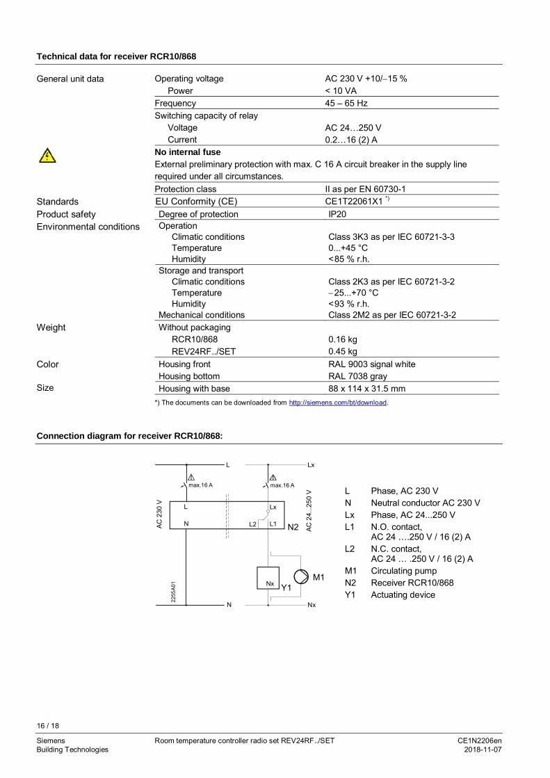
Technical data for receiver RCR10/868
Operating voltagePower
AC 230 V +10/-15 %< 10 VA
Frequency 45 – 65 HzSwitching capacity of relay
VoltageCurrent
AC 24…250 V0.2…16 (2) A
No internal fuseExternal preliminary protection with max. C 16 A circuit breaker in the supply linerequired under all circumstances.Protection class II as per EN 60730-1EU Conformity (CE) CE1T22061X1 *)
Degree of protection IP20Operation
Climatic conditionsTemperatureHumidity
Class 3K3 as per IEC 60721-3-30...+45 °C<85 % r.h.
Storage and transportClimatic conditionsTemperatureHumidity
Mechanical conditions
Class 2K3 as per IEC 60721-3-2-25...+70 °C<93 % r.h.Class 2M2 as per IEC 60721-3-2
Without packagingRCR10/868REV24RF../SET
0.16 kg0.45 kg
Housing frontHousing bottom
RAL 9003 signal whiteRAL 7038 gray
Housing with base 88 x 114 x 31.5 mm*) The documents can be downloaded from http://siemens.com/bt/download.
Connection diagram for receiver RCR10/868:
max.16 A
Lx
L1
Y1M1
N2
Nx
L
N L2
2255
A01
AC23
0V
AC24
...25
0V
Lx
NxN
L
max.16 AL Phase, AC 230 VN Neutral conductor AC 230 VLx Phase, AC 24...250 VL1 N.O. contact,
AC 24 ….250 V / 16 (2) AL2 N.C. contact,
AC 24 … .250 V / 16 (2) AM1 Circulating pumpN2 Receiver RCR10/868Y1 Actuating device
General unit data
StandardsProduct safetyEnvironmental conditions
Weight
Color
Size
17 / 18
Siemens Room temperature controller radio set REV24RF../SET CE1N2206enBuilding Technologies 2018-11-07
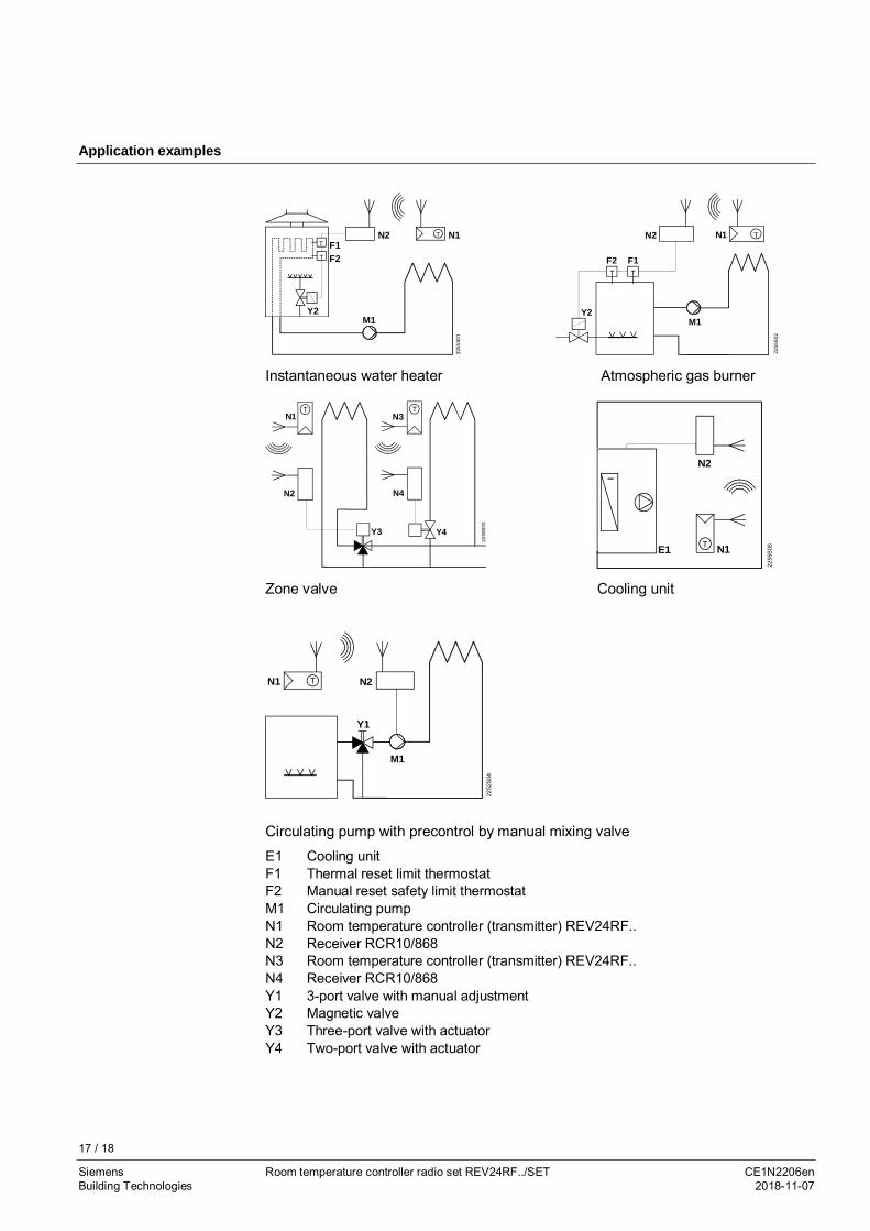
Application examples
T
T
F1F2
N2
M1Y2
2255
S01
N1T
F1F2
N2
M1Y2
2255
S02
T T
TN1
Instantaneous water heater Atmospheric gas burner
N1
Y4
2255
S03
Y3
N2
T
N4
TN3
T N1
2255
S05E1
N2
Zone valve Cooling unit
Y1
2252
S04
M1
N2TN1
Circulating pump with precontrol by manual mixing valve
E1 Cooling unitF1 Thermal reset limit thermostatF2 Manual reset safety limit thermostatM1 Circulating pumpN1 Room temperature controller (transmitter) REV24RF..N2 Receiver RCR10/868N3 Room temperature controller (transmitter) REV24RF..N4 Receiver RCR10/868Y1 3-port valve with manual adjustmentY2 Magnetic valveY3 Three-port valve with actuatorY4 Two-port valve with actuator

18 / 18
Siemens Room temperature controller radio set REV24RF../SET CE1N2206enBuilding Technologies 2018-11-07
Issued bySiemens Switzerland Ltd.Building Technologies DivisionInternational HeadquartersTheilerstrasse 1aCH-6300 ZugTel. +41 58 724 2424
© Siemens Switzerland Ltd, 2008 - 2018Technical specifications and availability subject to change without notice.
www.siemens.com/buildingtechnologies
Dimensions
Room temperature controller (transmitter) REV24RF..
Receiver RCR10/868