Reusable Launch Vehicle Operations and Maintenance Guideline … · 2006-09-22 · initial set of...
166
RTI International is a trade name of Research Triangle Institute 3000 N. Atlantic Avenue • Cocoa Beach, Florida 32931-5029 Contract No. DTFA01-01-D-03007 RTI Report No. RTI/ 08087/004/Vol1F January 12, 2004 Reusable Launch Vehicle Operations and Maintenance Guideline Inputs and Technical Evaluation Report: Subsystems - Volume 1 Final Report Prepared for Department of Transportation Federal Aviation Administration Associate Administrator for Commercial Space Transportation AST-200 Licensing and Safety Division 800 Independence Avenue, SW Washington, DC 20591 Center for Aerospace Technology
Transcript of Reusable Launch Vehicle Operations and Maintenance Guideline … · 2006-09-22 · initial set of...

RTI International is a trade name of Research Triangle Institute
3000 N. Atlantic Avenue • Cocoa Beach, Florida 32931-5029
Contract No. DTFA01-01-D-03007 RTI Report No. RTI/ 08087/004/Vol1F
January 12, 2004
Reusable Launch Vehicle Operations and Maintenance Guideline Inputs and
Technical Evaluation Report: Subsystems - Volume 1
Final Report
Prepared for
Department of Transportation Federal Aviation Administration
Associate Administrator for Commercial Space Transportation AST-200 Licensing and Safety Division
800 Independence Avenue, SW Washington, DC 20591
Center for Aerospace Technology

NOTICE This document is disseminated under the sponsorship of the U.S. Department of Transportation in the interest of information exchange. The United States Government assumes no liability for the contents or use thereof. The United States Government does not endorse products or manufacturers. Trade or manufacturer's names may appear herein solely when they are considered essential to the objective of the report. This document does not contain any proprietary information. Consult the FAA Commercial Space Transportation Office as to the appropriateness of use of any parts of this document on a specific project.

Reusable Launch Vehicle Operations and Maintenance Guideline Inputs and Technical Evaluation Report:
Subsystems - Volume 1
Final Report
Prepared by J. Timothy Middendorf
Janice Mendonca
of
Research Triangle Institute Center for Aerospace Technology Commercial Space Department
and
Uma Ferrell Tom Ferrell
of
Ferrell and Associates Consulting, Inc. 1261 Cobble Pond Way
Vienna, VA 22182
Prepared for Department of Transportation
Federal Aviation Administration Associate Administrator for Commercial Space Transportation
AST-200 Licensing and Safety Division 800 Independence Avenue, SW
Washington, DC 20591

Revision History Release Author Date Changes Incorporated
Draft RTI/FAAC 12/10/03 Report Draft Release to FAA Updated
Draft RTI 1/6/04 Chuck Larsen’s Comments Incorporated
Final RTI 1/12/04 Report Final

Table of Contents Executive Summary.............................................................................................i 1.0 Introduction ..............................................................................................1
1.1 Purpose ..................................................................................................1 1.2 Background ............................................................................................1 1.3 Scope .....................................................................................................3 1.4 Relationship to RLV Licensing................................................................4 1.5 Subsystem and Functional Context ........................................................5
2.0 Propulsion Subsystem ..........................................................................11 2.1 General Discussion ..............................................................................11 2.2 Guideline Input Considerations.............................................................13 2.3 Guideline Recommendations................................................................15
3.0 Communications Subsystem ................................................................21 3.1 General Discussion ..............................................................................21 3.2 Guideline Input Considerations.............................................................22 3.3 Guideline Recommendations................................................................24
4.0 Navigation/Guidance Subsystem .........................................................28 4.1 General Discussion ..............................................................................28 4.2 Guideline Input Considerations.............................................................31 4.3 Guideline Recommendations................................................................32
5.0 Avionics Subsystem ..............................................................................35 5.1 General Discussion ..............................................................................35 5.2 Guideline Input Considerations.............................................................35 5.3 Guideline Recommendations................................................................37
6.0 Flight Control Subsystem......................................................................38 6.1 General Discussion ..............................................................................38 6.2 Guideline Input Considerations.............................................................39 6.3 Guideline Recommendations................................................................40
7.0 Thermal Protection Subsystem ............................................................43 7.1 General Discussion ..............................................................................43 7.2 Guideline Input Considerations.............................................................44 7.3 Guideline Recommendations................................................................46
8.0 Electrical/Wiring Subsystem.................................................................49 8.1 General Discussion ..............................................................................49 8.2 Guideline Input Considerations.............................................................50 8.3 Guideline Recommendations................................................................52
9.0 Software Subsystem..............................................................................55 9.1 General Discussion ..............................................................................55 9.2 Guideline Input Considerations.............................................................55 9.3 Guideline Recommendations................................................................57
10.0 Structures Subsystem ...........................................................................60 10.1 General Discussion ..............................................................................60 10.2 Guideline Input Considerations.............................................................60 10.3 Guideline Recommendations................................................................62
11.0 Hydraulic Subsystem.............................................................................63 11.1 General Discussion ..............................................................................63

11.2 Guideline Input Considerations.............................................................63 11.3 Guideline Recommendations................................................................65
12.0 Pneumatic Subsystem...........................................................................68 12.1 General Discussion ..............................................................................68 12.2 Guideline Input Considerations.............................................................68 12.3 Guideline Recommendations................................................................70
13.0 Crew Subsystem ....................................................................................71 13.1 General Discussion ..............................................................................71 13.2 Guideline Input Considerations.............................................................71 13.3 Guideline Recommendations................................................................72
14.0 Payload/People Subsystem...................................................................73 14.1 General Discussion ..............................................................................73 14.2 Guideline Input Considerations.............................................................73 14.3 Guideline Recommendations................................................................75
15.0 Flight Safety Subsystem........................................................................76 15.1 General Discussion ..............................................................................76 15.2 Guideline Input Considerations.............................................................77 15.3 Guideline Recommendations................................................................79
16.0 Environmental Control and Life Support Subsystem .........................82 16.1 General Discussion ..............................................................................82 16.2 Guideline Input Considerations.............................................................82 16.3 Guideline Recommendations................................................................84
17.0 Tracking and Surveillance Subsystem.................................................87 17.1 General Discussion ..............................................................................87 17.2 Guideline Input Considerations.............................................................88 17.3 Guideline Recommendations................................................................89
18.0 Propellant Management Subsystem.....................................................91 18.1 General Discussion ..............................................................................91 18.2 Guideline Input Considerations.............................................................92 18.3 Guideline Recommendations................................................................93
19.0 Health Monitor and Data Recorder Subsystem ...................................95 19.1 General Discussion ..............................................................................95 19.2 Guideline Input Considerations.............................................................96 19.3 Guideline Recommendations................................................................97
20.0 Landing and Recovery Subsystem.......................................................99 20.1 General Discussion ..............................................................................99 20.2 Guideline Input Considerations...........................................................100 20.3 Guideline Recommendations..............................................................101
21.0 Ground Support Equipment ................................................................102 21.1 General Discussion ............................................................................102 21.2 Guideline Input Considerations...........................................................103 21.3 Guideline Recommendations..............................................................104
22.0 Facilities................................................................................................107 22.1 General Discussion ............................................................................107 22.2 Guideline Input Considerations...........................................................108 22.3 Guideline Recommendations..............................................................110

Appendix A: Human Factors Considerations...............................................111 Appendix B: Design Considerations.............................................................117 Appendix C: Acronyms/Terminology............................................................142 Appendix D: RLV Guideline Input Suggestion Form ...................................151 Endnotes .........................................................................................................153
List of Figures
Figure 1 RLV Context Diagram.............................................................................6 Figure 2 RLV O&M Context ..................................................................................7 Figure 3 Guidance Document Process .................................................................8 Figure 4 Subsystems ............................................................................................9 Figure 5 Subsystem Interaction Diagram............................................................10 Figure 6 Propulsion Breakout and Issues ...........................................................12 Figure 7 Navigation and Guidance Flow .............................................................30 Figure 8 Types of Thermal Protection Systems ..................................................44 Figure 9 Power Functions ...................................................................................50 Figure 10 Manual FSS (today) ............................................................................76 Figure 11 Autonomous FSS (future) ...................................................................77 Figure 12 Diagram of Kistler Orbital Vehicle Recovery Sequence......................99 Figure 13 Extended Mission Control System ....................................................108 Figure 14 Design Consistency ..........................................................................118
List of Tables Table 1 Navigation and Guidance Error Sources................................................30

This page intentionally left blank.

Guideline Inputs Subsystems – Vol 1 Executive Summary
i
Executive Summary Development of commercial Reusable Launch Vehicles (RLVs) remains a great interest to many private companies. The appeal rests in an RLV’s ability to support multiple mission types (e.g., cargo and “tourism”) and amortized development costs over the life of the operational vehicle. Commercial RLV companies plan to use both existing and new technologies in the design/development of the vehicle and its subsystems. RLV Operations and Maintenance (O&M) practices have the potential to affect public safety; therefore, the FAA’s Office of Commercial Space Transportation (FAA/AST) is in the process of developing guidelines for RLV O&M practices. These guidelines may be used in evaluating an RLV developer/operator’s license application. This Guideline Input and Technical Evaluation Report is intended to capture an initial set of Guideline Inputs (GIs) and Guideline Input Considerations (GICs) ordered around the various subsystems that are likely to be used in RLV O&M. This volume is the first of five such volumes. While this volume is expressly focused on subsystems, the subsequent 4 volumes are function-based: Operations, Maintenance, Training, and Approval. A total of twenty-one subsystems (nineteen on-board subsystems and two ground-based supporting subsystems) have been identified for development of guideline inputs. These subsystems include traditional fixed wing aircraft types, such as flight controls, avionics, and navigation, to those more often associated with space operations such as thermal protection systems and flight safety systems. The focus and intent of this Delivery Order 4 (DO4) effort has been to capture those items that should be considered during O&M of these various subsystems. In order to ensure these guidelines have been considered, RTI proposes that a series of manuals be required as part of an RLV developer’s final license application: Operations, Maintenance, Training, and Approval. These manuals would speak to the current requirements contained in the RLV Mission License Rule (14 CFR Part 431) and would also allow an RLV developer/operator to specify how they intend to address FAA/AST O&M Guidelines. In this way, the RLV developer/operator has the ability to stipulate which of these guidelines are relevant for their chosen vehicle design and ensures that O&M public safety considerations have been fully addressed. In summary, the Guideline Inputs in this volume and the associated function-based volumes (Volumes 2 through 5) are intended to serve as input to a common set of criteria by which the FAA and the industry can assess public safety aspects of RLV O&M processes. As the RLV industry matures, it is expected that additional guidelines will be developed; consequently, these Guideline Input volumes are considered to be living documents that will evolve as the industry evolves.

Guideline Inputs Subsystems – Vol 1 Executive Summary
ii
This page intentionally left blank.

Guideline Inputs Subsystems – Vol 1 Introduction
1
1.0 Introduction Reusable Launch Vehicles (RLVs) will require guidelines and regulatory language to be developed for new approaches in both Operations and Maintenance (O&M). These approaches may have a direct effect on public safety where RLVs are being operated and maintained. The Guideline Inputs in this volume and the associated function-based volumes (Volumes 2 through 5) are intended to serve as a common set of criteria by which both the FAA and the industry can assess O&M processes and systems to ensure that public safety is protected. As such, these Volumes are considered “living” documents that will continue to mature with the RLV Industry.
1.1 Purpose The Guideline Inputs (GIs) and Guideline Input Considerations (GIs) contained in this Subsystems volume (Vol 1) provide basic guideline considerations for the identified RLV Subsystems associated with RLV O&M. In this context, Subsystems are considered any hardware or software associated with an RLV to include ground support hardware which if not operated or maintained with certain considerations given, may make the RLV and its flight unsafe to the public.
1.2 Background These Guideline Inputs are the result of a focused effort by FAA’s Office of Commercial Space Transportation (FAA/AST) to facilitate a common understanding between both the regulator and the industry on what is expected from RLV operators and maintainers in order to ensure public safety. The creation of these Guideline Inputs was prompted by the response to an FAA/AST presentation of an RLV O&M White Paper to the Commercial Space Transportation Advisory Committee (COMSTAC) in October of 1999. Industry feedback to that paper along with FAA-directed research activities led to the initiation of an information-only Rulemaking Project Record (RPR) intended to establish formal rules for RLV O&M. These Guideline Inputs represent an interim step toward a Notice of Proposed Rulemaking (NPRM) for RLV O&M and are intended to serve as a means by which those items requiring formalization as a rule can be identified and validated both by the FAA and by industry. However, it should be recognized that an NPRM would only be developed after the industry is sufficiently mature. RTI used the Systems Functions and Procedural Items identified during the second Delivery Order (DO2) of this effort1 as a starting point for subsequent investigation. It was determined that a general model was needed to place the Systems Functions and Procedural Items in context. This led to the identification of a list of subsystems and functions that have served as the organizing model for all subsequent work associated with this effort. The next few sections provide the work statement for this current activity, DO4, as well as an overview of the context now being employed for the RLV O&M effort.

Guideline Inputs Subsystems – Vol 1 Introduction
2
1.2.1 Statement of Understanding A Statement of Understanding between the FAA and the RTI Team has been developed to govern each of the RLV O&M tasks. The following text presents the Statement of Understanding (SOU) developed for this effort under DO4:
“The RTI Team will continue to support FAA/AST-100 in the development of RLV O&M guidelines and technical evaluation criteria. This task will build on the work done in the RLV O&M Top-Down Analyses performed under DO2 and DO3 of the reference contract. In particular, the RTI Team will develop material that will help FAA/AST-100 identify the O&M technical evaluation criteria and performance standards for safety-critical RLV subsystems and functions. In performing the specified work, particular attention will be made to any unique features, including proven and unproven RLV O&M activities, and their correlation to any historic lessons-learned in the Space Shuttle, airline and RLV research community. The outputs of this research (DO4) and the next research phase are to be presented in five RLV O&M Guideline Inputs and Technical Evaluation Report volumes: Subsystems -Volume 1, Operations - Volume 2, Maintenance - Volume 3, Training - Volume 4, and Approval - Volume 5. Under DO4, RTI will deliver the first two of these volumes: Subsystems - Volume 1 and Operations - Volume 2. The following list summarizes the specific topics that will be addressed under this DO:
1. Guideline inputs and rationale: The major RLV O&M subsystem and function safety items will be developed into guideline inputs along with the supporting rationale. These will be presented in a format approved by FAA/AST.
2. Further refinement of the Subsystem and Functional Decomposition: A number of modifications to the current Functional Decomposition diagrams have been identified including the need to add Functions for Contingency Operations, Vehicle Configuration Management, and Simulation Requirements to name just a few. The Functional Decomposition diagrams will be modified to reflect the functional refinements.
3. Continued data collection from the aviation and space domains: Continue to extract information from traditional aviation, the Space Shuttle, and other RLV programs in support of the guideline and technical evaluation criteria development.
4. Continued exploration of Special Topics: In previous Delivery Orders, certain topics were identified for further research such as inter/intra-agency coordination, human factors, design dependencies to name a few. These topics will be furthered as time allows in DO4.”

Guideline Inputs Subsystems – Vol 1 Introduction
3
1.3 Scope The following Guideline Inputs are intended for use by the RLV Industry and the FAA’s Office of Commercial Space Transportation in the preparation and evaluation of RLV license applications and O&M plans. The scope of these guidelines is bounded by the jurisdictional authority provided to the FAA by Congress. Additionally, these Guideline Inputs do not affect or amend the content of the licensing rules, but rather are designed to help the FAA and RLV Industry jointly ensure the rules are both followed and applied in a consistent manner.
1.3.1 Guideline Input Philosophy Although there is general agreement about the various technologies expected to be employed in RLV O&M, the RLV Industry is clearly evolving. These Guideline Inputs have been developed to serve as a repository for best/recommended practices. It is expected that a portion of these practices will ultimately be formalized in a federal regulation that will govern the RLV Industry. Some inputs may have to be revised as newer technologies are developed and better procedures emerge as the industry matures. A wide variety of sources were reviewed and analyzed to develop the content of these Guideline Inputs. Primary consideration was given to lessons-learned drawn from the aviation and space community. In some cases, these lessons are explicit and are clearly technology-independent public safety issues and thus could be written as a requirement. In these cases, Guideline Inputs (GIs) have been developed and the term “shall” is used. These GIs are numbered sequentially with a Subsystem prefix (e.g., The first Propulsion Subsystem Guideline Input is numbered Prop GI-1.) It is reasonable to assume that these items will be included in any subsequent rule development governing RLV O&M. In many cases, however, the lesson or issue being discussed is less clearly defined and sufficient experience or research is not available to validate the lesson or issue. Others are technology dependent and only apply to a narrow set of RLV concepts. For these cases, Guideline Input Considerations (GICs) have been developed and the term “should” is used. These GICs are numbered sequentially with a Subsystem prefix (e.g., the first Propulsion Subsystem Guideline Input Consideration is numbered Prop GIC-1.) While these are candidates for inclusion in any subsequent rulemaking, it is reasonable to assume that further work may be needed before such a rule is promulgated. Although not included in the scope of this research effort, Human Factors considerations that were identified are presented in Appendix A: Human Factors Considerations. Additionally, any design considerations that were identified are listed in Appendix B: Design Considerations of this document. Please note that there are many other safety issues that an RLV operator needs to consider for the safety of operators and technicians; FAA/AST is currently

Guideline Inputs Subsystems – Vol 1 Introduction
4
charged with only public safety concerns. Further, no delineation of when and how rules would be applied was made in these considerations. Some of these guidelines may be considered during the licensing stage while others may be considered as repeated launches are executed for the same vehicle under the launch license. Within the following sections, OSHA appears in many of the Inter/Intra Agency Issues subsections. Although OSHA is concerned with worker safety and not general public, the authors of this document are of the opinion that jurisdictional issues need to be addressed for cases where a worker safety situation has the potential to escalate into a public safety concern (e.g., a hazardous material spill). References to supporting data or incidents are included to provide the background, rationale, and justification for the inputs. Endnotes are used for specific citations within the document.
1.3.2 Suggestion Form As noted earlier, these Guideline Inputs are expected to evolve as the industry matures and additional data becomes available, either from research or through actual flight activity. The reader is encouraged to share their experiences and knowledge through use of the Suggestion Form in Appendix D: RLV Guideline Input Suggestion Form. It is the FAA’s intent to periodically review these Guideline Inputs to ensure they are current, particularly with respect to issues that are technology dependent.
1.4 Relationship to RLV Licensing The impetus for this effort was to provide a common set of criteria related to O&M that could be used by FAA AST to evaluate RLV developer/operator license applications. The Guideline Inputs and the related Guideline Input Considerations contained in this volume are focused on subsystems with particular emphasis placed on issues unique to the subsystem being addressed and could pose a risk to the public if not followed. RLV developer/operators are expected to explain how each of these Guidelines is satisfied for their particular vehicle design. In DO2, the RTI team proposed a formal set of readiness reviews, one for operations and one for maintenance. In addition, the concept of Instructions for Continued Flightworthiness (ICF) and an Operating or Flight Manual was introduced. The reviews were intended to be focused activities within the context of the overall mission readiness review required by the RLV licensing rule. The Operations Manual was designed to lend form to the mission operational requirements while the ICF filled a gap in the current licensing description by addressing those considerations for turnaround of an RLV and preparation for subsequent flights. Since its introduction, the FAA has adopted the term Maintenance Program Plan in place of ICF.

Guideline Inputs Subsystems – Vol 1 Introduction
5
The RTI Team believes that to further clarify the licensing rule and to better align with the proposed guideline structure, two additional data items should be provided to AST by the RLV developer/operator for review. These two items are a Training Manual and an Approval Manual. Note that this data can easily be packaged as part of the Maintenance Program Plan and Operations Manual if the license applicant so chooses provided that the data is clearly identified. The four documents, taken together, will allow individual RLV developer/operators to address the Guideline Inputs and Considerations contained in this volume and the four functional volumes for their specific vehicle. At the same time, the use of a common set of Guidelines will help FAA/AST evaluate the appropriateness and completeness of the provided data in a uniform manner. No separate Subsystem Manual is suggested or expected. Rather, the functionally-oriented manuals should address the Subsystems as applicable for a particular operation, maintenance activity, training element, or approval function as needed. To ensure that all issues are completely addressed, careful attention should be paid to ensure that all four manuals are consistent with one another. Please refer to the specific functional Guidelines for more details on the manuals.
1.5 Subsystem and Functional Context Functional Guideline Inputs (GIs) and Guideline Input Considerations (GICs) have been developed for those activities associated with operations and maintenance, as well as the related areas of training and approval. Figure 1 illustrates how these relate to one another and where they fit into the broader scope of RLV licensing, approvals, and RLV development. It should be noted that this effort considers only the items to the right of the vertical line in Figure 1. These items are highlighted in Figure 2.

Guideline Inputs Subsystems – Vol 1 Introduction
6
Figure 1 RLV Context Diagram
Proposed FAR 4xx(s)
DemonstrateFlightworthiness
Train
Fly(Operations)
Proposed FAR 491
Design/Production impacts:Operations
Design/Production impacts: Maintenance
Operating Approval
Maintain(Maintenance)
Proposed FAR 443
Flight Ground
Approve(Personnel/Facilities/Equipment/Material/
Procedures)
Proposed FAR 4xx(s)
Design PrototypeDesign SafetyApproval
Launch/Re-entry License
FAR 431
Produce Production
ProcessApproval
Develop Business
Plan IdentifyMarket
Continued Flightworthiness
Accident/Incident Lessons Learned

Guideline Inputs Subsystems – Vol 1 Introduction
7
Figure 2 RLV O&M Context It should also be noted that this top-down analysis is being supplemented by a bottom-up analysis effort being conducted by the FAA. The two efforts taken together are intended to serve as the basis for guidance development in the area of RLV O&M, see Figure 3.
Proposed FAR 4xx(s)
Train
Fly(Operations)
Proposed FAR 491
Operating Approval
Maintain(Maintenance)
Proposed FAR 443
Flight Ground
Approve(Personnel/Facilities/Equipment/Material/
Procedures)
Launch/Re- entry License
FAR 431
Continued Flightworthiness

Guideline Inputs Subsystems – Vol 1 Introduction
8
Figure 3 Guidance Document Process As shown in Figure 3, the ultimate product of this activity is expected to be one or more Guidance documents from the FAA. The FAA has realized that given the current level of maturity within the commercial RLV industry, the best approach to take in the near-term is the production of guidelines that can be employed by both the FAA and industry to evaluate proposed RLV’s O&M activities on public safety. With this in mind, the top-down analysis has been organized around a ‘divide and conquer’ approach where individual subsystems and functions are examined for their potential contribution to public safety. It should be noted that the functions depicted and discussed are presented in terms of requiring an action, hence the term function. This is in contrast to the Subsystems addressed in this volume that are vehicle-centric and typically hardware and software related.
Bottoms-Up Analysis
FAA GuidanceProducts
OrdersAdvisory Circulars
Rules
Guidelines
FAA/AST
Training/Approval(Part 465 )
Maintenance(Part 443)
Operations(Parts 465 & 491)
Integrate
Updates
Vol 5 Guide-
lineInputs
Vol 4 Guide-
lineInputsUpdates
Vol 3 Guide-
lineInputsUpdates
Vol 2 Guide-
lineInputsUpdates
Vol 1 Guide-
lineInputsUpdates
Top-Down AnalysisRTI/
FAAC
Proposed FAR 4xx(s)
DemonstrateFlightworthiness
Train
Fly(Operations)
Proposed FAR 491
Design/Production impacts:Operations
Design/Production impacts:Maintenance
Operating Approval
Maintain(Maintenance)Proposed FAR 443
Flight Ground
Approve(Personnel/Facil ities/Equipment/Material/
Procedures)
Proposed FAR 4xx(s)
Design PrototypeDesign Safety
Approval
Launch/Re-entry License
FAR 431
ProduceProduction
ProcessApproval
DevelopBusiness
PlanIdentifyMarket
Continued Flightworthiness
CONTEXT
ApprovalTraining
MaintenanceOperations
Subsystems
TrainingAdministerKnowledge TestAdministerPractical Test
DevelopTraining
PerformTraining
TestReport & Record
Develop CurriculumDevelop Materials
Develop CurrencyRequirements
Develop SimulatorsDevelop Faci lities
Train Subsystems
Train Functions
Train Ground Ops
Train Flight Ops
TrainMaintenance
Train FlightCrewTrainMaintainers/Technicians
Train OtherPersonnel
TrainMaintainers/Technicians
Train FlightCrewTrain OtherPersonnel
PersonnelTraining
Approval
Approve GroundOps Personnel
Approve FlightOps Personnel
ApproveMaintenancePersonnel
Approve Ground CrewApprove Other Personnel
Approve Maintainers/Technicians
Approve Flight CrewApprove Other Personnel
PersonnelApproval
Facilities/Equip/Material/ProceduresApproval
ApproveFac/Equip/Mat/ProcsAcceptance
ApproveOperations Fac/Equip/Mat/Procs
ApproveMaintenanceFac/Equip/Mat/Procs
Approve TrainingFac/Equip/Mat
Approve CurriculumApprove Materials
Approve Training CurrencyRequirements
Approve Training SimulatorsApprove Training Faci lities
Approve Other PersonnelApproval(Personnel/Facilities/Equipment/Material/Procedures)
Approve Ops MaterialsApprove Ops EquipmentApprove Ops Faci lities
Approve Maint MaterialsApprove Maint EquipmentApprove Maint Faci lities
Develop /ApproveAcceptance ScenariosDevelop /ApproveAcceptanceMaterials
Apply Proficiency Standards
Develop /ApproveAcceptance Equip/SimulatorsDevelop /ApproveAcceptance Facilities
Approve Maint Procedures
Approve Ops Procedures
Approve Training Procs
Approve AcceptanceProcedures
SubSystemsPropulsion
CommunicationsNav/Guidance
Flight ControlTPS
SoftwareStructuresHydraulicsPneumatics
Payload/People SystemsCrew Systems
Flight Safety SystemEnvironmental SystemsSurveillance System
Propellant Management System
Health Monitor & Data Recorders
Land/Recover y Systems
Facili ties
Ground Support Equipment
Operations
Approval
Training
Maintenance
Operations
(Operations)
Operations
Launch
Fly
FlightOperations
PerformGroundOperations
Prepare GroundOperations
Recover
Land
Plan FlightMonitor Vehicle Health
Assess Over-Flight RiskAnalyze Impact Li mit Lines
Perform COLA & COMBOInteract with ATC/STC/Coast Guard
Plan Trajectory
TransportIntegrate Vehicle
Handle Hazard MaterialProtect PersonnelManage Propellant
Hazard Material Handling
Monitor Vehicle Health
Payload/Passenger EgressTransport
Communicate
Personnel ProtectionManage Propellant
Monitor Vehicle Health
Manage Fl ightLiftoff
Manage Environment
Interact with ATC/STCCommunicate
Monitor Vehicle Health
Manage FlightCmd & Ctrl Flight SafetyManage Environment
Interact with ATC/STCCommunicate
Monitor Vehicle Health
Manage FlightCmd & Ctrl Fl ight Safety
Manage Flight
Interact with ATC/STCCommunicate
OperateGSE/Facilties
De-Orbit/Re-enter
Control FlightTrack VehicleSurveil Fl ightEnvironment
Propel
Monitor Vehicle Health
Manage FlightCmd & Ctrl Flight SafetyManage Environment
Interact with ATC/STCCommunicate
Control FlightTrack Vehicle
Propel
Surveil FlightEnvironment
StageControl FlightTrack Vehicle
Survei l Flight Environment
Maintenance
MaintainSystem
(Maintenance)Perform
Turn AroundMaintenance
PerformPart/Subsystem
Life-CycleReplacement
Correct Deficiencies
PerformPost Flight Inspections
PerformUn-ScheduledMaintenance
Diagnose
InspectRepairAlter
Report
Diagnose
InspectRepair
Alter
Report
PerformPre-Flight Inspection
PerformInterval Dri venMaintenance
PerformScheduledMaintenance
Return to Service
Return to Service
Bottoms-Up Analysis
FAA GuidanceProducts
OrdersAdvisory Circulars
Rules
Guidelines
FAA/ASTFAA/AST
Training/Approval(Part 465 )
Maintenance(Part 443)
Operations(Parts 465 & 491)
Integrate
Updates
Vol 5 Guide-
lineInputsUpdates
Vol 5 Guide-
lineInputs
Vol 4 Guide-
lineInputsUpdates
Vol 4 Guide-
lineInputsUpdates
Vol 3 Guide-
lineInputsUpdates
Vol 3 Guide-
lineInputsUpdates
Vol 2 Guide-
lineInputsUpdates
Vol 1 Guide-
lineInputsUpdates
Top-Down AnalysisRTI/
FAACRTI/
FAAC
Proposed FAR 4xx(s)
DemonstrateFlightworthiness
Train
Fly(Operations)
Proposed FAR 491
Design/Production impacts:Operations
Design/Production impacts:Maintenance
Operating Approval
Maintain(Maintenance)Proposed FAR 443
Flight Ground
Approve(Personnel/Facil ities/Equipment/Material/
Procedures)
Proposed FAR 4xx(s)
Design PrototypeDesign Safety
Approval
Launch/Re-entry License
FAR 431
ProduceProduction
ProcessApproval
DevelopBusiness
PlanIdentifyMarket
Continued Flightworthiness
CONTEXT
Proposed FAR 4xx(s)
DemonstrateFlightworthiness
Train
Fly(Operations)
Proposed FAR 491
Design/Production impacts:Operations
Design/Production impacts:Maintenance
Operating Approval
Maintain(Maintenance)Proposed FAR 443
Flight Ground
Approve(Personnel/Facil ities/Equipment/Material/
Procedures)
Proposed FAR 4xx(s)
Design PrototypeDesign Safety
Approval
Launch/Re-entry License
FAR 431
ProduceProduction
ProcessApproval
DevelopBusiness
PlanIdentifyMarket
Continued Flightworthiness
Proposed FAR 4xx(s)
DemonstrateFlightworthiness
Train
Fly(Operations)
Proposed FAR 491
Design/Production impacts:Operations
Design/Production impacts:Maintenance
Operating Approval
Maintain(Maintenance)Proposed FAR 443
Flight Ground
Approve(Personnel/Facil ities/Equipment/Material/
Procedures)
Proposed FAR 4xx(s)
Design PrototypeDesign Safety
Approval
Launch/Re-entry License
FAR 431
ProduceProduction
ProcessApproval
DevelopBusiness
PlanIdentifyMarket
Continued Flightworthiness
CONTEXT
ApprovalTraining
MaintenanceOperations
Subsystems
TrainingAdministerKnowledge TestAdministerPractical Test
DevelopTraining
PerformTraining
TestReport & Record
Develop CurriculumDevelop Materials
Develop CurrencyRequirements
Develop SimulatorsDevelop Faci lities
Train Subsystems
Train Functions
Train Ground Ops
Train Flight Ops
TrainMaintenance
Train FlightCrewTrainMaintainers/Technicians
Train OtherPersonnel
TrainMaintainers/Technicians
Train FlightCrewTrain OtherPersonnel
PersonnelTrainingTrainingAdministerKnowledge TestAdministerPractical Test
DevelopTraining
PerformTraining
TestReport & Record
Develop CurriculumDevelop Materials
Develop CurrencyRequirements
Develop SimulatorsDevelop Faci lities
Train Subsystems
Train Functions
Train Ground Ops
Train Flight Ops
TrainMaintenance
Train FlightCrewTrainMaintainers/Technicians
Train OtherPersonnel
TrainMaintainers/Technicians
Train FlightCrewTrain OtherPersonnel
PersonnelTraining
AdministerKnowledge TestAdministerPractical Test
DevelopTraining
PerformTraining
TestReport & Record
Develop CurriculumDevelop Materials
Develop CurrencyRequirements
Develop SimulatorsDevelop Faci lities
Train Subsystems
Train Functions
Train Ground Ops
Train Flight Ops
TrainMaintenance
Train FlightCrewTrainMaintainers/Technicians
Train OtherPersonnel
TrainMaintainers/Technicians
Train FlightCrewTrain OtherPersonnel
PersonnelTraining
Approval
Approve GroundOps Personnel
Approve FlightOps Personnel
ApproveMaintenancePersonnel
Approve Ground CrewApprove Other Personnel
Approve Maintainers/Technicians
Approve Flight CrewApprove Other Personnel
PersonnelApproval
Facilities/Equip/Material/ProceduresApproval
ApproveFac/Equip/Mat/ProcsAcceptance
ApproveOperations Fac/Equip/Mat/Procs
ApproveMaintenanceFac/Equip/Mat/Procs
Approve TrainingFac/Equip/Mat
Approve CurriculumApprove Materials
Approve Training CurrencyRequirements
Approve Training SimulatorsApprove Training Faci lities
Approve Other PersonnelApproval(Personnel/Facilities/Equipment/Material/Procedures)
Approve Ops MaterialsApprove Ops EquipmentApprove Ops Faci lities
Approve Maint MaterialsApprove Maint EquipmentApprove Maint Faci lities
Develop /ApproveAcceptance ScenariosDevelop /ApproveAcceptanceMaterials
Apply Proficiency Standards
Develop /ApproveAcceptance Equip/SimulatorsDevelop /ApproveAcceptance Facilities
Approve Maint Procedures
Approve Ops Procedures
Approve Training Procs
Approve AcceptanceProcedures
SubSystemsPropulsion
CommunicationsNav/Guidance
Flight ControlTPS
SoftwareStructuresHydraulicsPneumatics
Payload/People SystemsCrew Systems
Flight Safety SystemEnvironmental SystemsSurveillance System
Propellant Management System
Health Monitor & Data Recorders
Land/Recover y Systems
Facili ties
Ground Support Equipment
Operations
Approval
Training
Maintenance
PropulsionCommunicationsNav/Guidance
Flight ControlTPS
SoftwareStructuresHydraulicsPneumatics
Payload/People SystemsCrew Systems
Flight Safety SystemEnvironmental SystemsSurveillance System
Propellant Management System
Health Monitor & Data Recorders
Land/Recover y Systems
Facili ties
Ground Support Equipment
Operations
Approval
Training
Maintenance
Operations
(Operations)
Operations
Launch
Fly
FlightOperations
PerformGroundOperations
Prepare GroundOperations
Recover
Land
Plan FlightMonitor Vehicle Health
Assess Over-Flight RiskAnalyze Impact Li mit Lines
Perform COLA & COMBOInteract with ATC/STC/Coast Guard
Plan Trajectory
TransportIntegrate Vehicle
Handle Hazard MaterialProtect PersonnelManage Propellant
Hazard Material Handling
Monitor Vehicle Health
Payload/Passenger EgressTransport
Communicate
Personnel ProtectionManage Propellant
Monitor Vehicle Health
Manage Fl ightLiftoff
Manage Environment
Interact with ATC/STCCommunicate
Monitor Vehicle Health
Manage FlightCmd & Ctrl Flight SafetyManage Environment
Interact with ATC/STCCommunicate
Monitor Vehicle Health
Manage FlightCmd & Ctrl Fl ight Safety
Manage Flight
Interact with ATC/STCCommunicate
OperateGSE/Facilties
De-Orbit/Re-enter
Control FlightTrack VehicleSurveil Fl ightEnvironment
Propel
Monitor Vehicle Health
Manage FlightCmd & Ctrl Flight SafetyManage Environment
Interact with ATC/STCCommunicate
Control FlightTrack Vehicle
Propel
Surveil FlightEnvironment
StageControl FlightTrack Vehicle
Survei l Flight Environment
Operations
(Operations)
Operations
Launch
Fly
FlightOperations
PerformGroundOperations
Prepare GroundOperations
Recover
Land
Plan FlightMonitor Vehicle Health
Assess Over-Flight RiskAnalyze Impact Li mit Lines
Perform COLA & COMBOInteract with ATC/STC/Coast Guard
Plan Trajectory
TransportIntegrate Vehicle
Handle Hazard MaterialProtect PersonnelManage Propellant
Hazard Material Handling
Monitor Vehicle Health
Payload/Passenger EgressTransport
Communicate
Personnel ProtectionManage Propellant
Monitor Vehicle Health
Manage Fl ightLiftoff
Manage Environment
Interact with ATC/STCCommunicate
Monitor Vehicle Health
Manage FlightCmd & Ctrl Flight SafetyManage Environment
Interact with ATC/STCCommunicate
Monitor Vehicle Health
Manage FlightCmd & Ctrl Fl ight Safety
Manage Flight
Interact with ATC/STCCommunicate
OperateGSE/Facilties
De-Orbit/Re-enter
Control FlightTrack VehicleSurveil Fl ightEnvironment
Propel
Monitor Vehicle Health
Manage FlightCmd & Ctrl Flight SafetyManage Environment
Interact with ATC/STCCommunicate
Control FlightTrack Vehicle
Propel
Surveil FlightEnvironment
StageControl FlightTrack Vehicle
Survei l Flight Environment(Operations)
Operations
Launch
Fly
FlightOperations
PerformGroundOperations
Prepare GroundOperations
Recover
Land
Plan FlightMonitor Vehicle Health
Assess Over-Flight RiskAnalyze Impact Li mit Lines
Perform COLA & COMBOInteract with ATC/STC/Coast Guard
Plan Trajectory
TransportIntegrate Vehicle
Handle Hazard MaterialProtect PersonnelManage Propellant
Hazard Material Handling
Monitor Vehicle Health
Payload/Passenger EgressTransport
Communicate
Personnel ProtectionManage Propellant
Monitor Vehicle Health
Manage Fl ightLiftoff
Manage Environment
Interact with ATC/STCCommunicate
Monitor Vehicle Health
Manage FlightCmd & Ctrl Flight SafetyManage Environment
Interact with ATC/STCCommunicate
Monitor Vehicle Health
Manage FlightCmd & Ctrl Fl ight Safety
Manage Flight
Interact with ATC/STCCommunicate
OperateGSE/Facilties
De-Orbit/Re-enter
Control FlightTrack VehicleSurveil Fl ightEnvironment
Propel
(Operations)
Operations
Launch
Fly
FlightOperations
PerformGroundOperations
Prepare GroundOperations
Recover
Land
Plan FlightMonitor Vehicle Health
Assess Over-Flight RiskAnalyze Impact Li mit Lines
Perform COLA & COMBOInteract with ATC/STC/Coast Guard
Plan Trajectory
TransportIntegrate Vehicle
Handle Hazard MaterialProtect PersonnelManage Propellant
Hazard Material Handling
Monitor Vehicle Health
Payload/Passenger EgressTransport
Communicate
Personnel ProtectionManage Propellant
Monitor Vehicle Health
Manage Fl ightLiftoff
Manage Environment
Interact with ATC/STCCommunicate
Monitor Vehicle Health
Manage FlightCmd & Ctrl Flight SafetyManage Environment
Interact with ATC/STCCommunicate
Monitor Vehicle Health
Manage FlightCmd & Ctrl Fl ight Safety
Manage Flight
Interact with ATC/STCCommunicate
OperateGSE/Facilties
De-Orbit/Re-enter
Control FlightTrack VehicleSurveil Fl ightEnvironment
Propel
Monitor Vehicle Health
Manage FlightCmd & Ctrl Flight SafetyManage Environment
Interact with ATC/STCCommunicate
Control FlightTrack Vehicle
Propel
Surveil FlightEnvironment
StageControl FlightTrack Vehicle
Survei l Flight Environment
Maintenance
MaintainSystem
(Maintenance)Perform
Turn AroundMaintenance
PerformPart/Subsystem
Life-CycleReplacement
Correct Deficiencies
PerformPost Flight Inspections
PerformUn-ScheduledMaintenance
Diagnose
InspectRepairAlter
Report
Diagnose
InspectRepair
Alter
Report
PerformPre-Flight Inspection
PerformInterval Dri venMaintenance
PerformScheduledMaintenance
Return to Service
Return to Service

Guideline Inputs Subsystems – Vol 1 Introduction
9
1.5.1 Subsystem and Functional Decomposition 1.5.1.1 Subsystem The Subsystems addressed in this document are listed on the right side of Figure 4. These Subsystems correlate to the Subsystem Functions that were described in the DO 2 report. One minor change from the DO 2 list is that the Payload Subsystem Function was renamed the Payload/People Subsystem.
Figure 4 Subsystems Between the DO2 effort and the current work, a considerable amount of data collection was accomplished and captured in a series of DO3 reports. This intermediate work attempted to organize subsystem data around definitions; a general discussion of the subsystem; major related safety issues; inter/intra agency coordination considerations; cross-correlations to other subsystems and/or functions; and any additional considerations. The current volume presents this same data with some extensions and deletions in the form of Guideline Inputs (GIs) and Guideline Input Considerations (GICs). During the earlier effort, it became apparent that the interactions between subsystems could have a substantial impact on public safety. A notional view of subsystem interactions was developed as in shown in Figure 5. Note that the subsystems are divided into two groups: those off-board the RLV and those on-
Propulsion Communications Nav/Guidance
Flight Control Avionics
TPS Electrical/Wiring
Software Structures Hydraulics
Pneumatics
Payload/People Crew
Flight Safety Environmental Control and Life Support
Tracking and Surveillance
Propellant Management
Health Monitor & Data Recorders
Land/Recovery
Facilities Ground Support Equipment
Operations
Approval
Training
Maintenance

Guideline Inputs Subsystems – Vol 1 Introduction
10
board the RLV. Facilities and Ground Support Equipment are the only subsystems with entirely off-board components. A white box indicates those subsystems that are primarily on-board with similar functionality in off-board components. For example, the Propellant Management System will have elements on the RLV for management during fueling and flight, but the storage tanks, plumbing, and fueling management controls are off-board in GSE and/or Facilities. Subsystems having gray boxes are considered to have only RLV elements.
Figure 5 Subsystem Interaction Diagram
As indicated by the legend, interactions may be ‘one to one,’ ‘one to many,’ or even ‘many to many.’ Likewise, the direction-of-interaction varies: some subsystems only distribute, some only consume data, while most do both. Although subsystem interactions will vary based on the individual RLV design and operational concept, this diagram highlights the need to understand RLV subsystem interdependencies (e.g., Software to Flight Safety System) in order to ensure public safety during RLV O&M activities.
Propulsion
Communications
Nav/Guidance/Control
Avionics
TPS
Electrical/Wiring
Software
Structures
Actuators (Hydraulics/Pneumatics)
Payload/People
Crew
Flight Safety System
Environmental and Life Support
Tracking and Surveillance
Propellant Management
Health Monitor & Data Recorders Land/Recovery
On RLVOff RLV
Facilities Ground Support Equipment
LEGEND: Indicate Subsystems that are both on the RLV and off
Borders indicate Subsystems that have a primary distribution or reception role.
text text
Indicates interaction of subsystems
Indicates distribution and reception links between subsystems text text

Guideline Inputs Subsystems – Vol 1 Propulsion Subsystem
11
2.0 Propulsion Subsystem The Propulsion Subsystem is defined as the hardware that provides the necessary force to generate RLV motion.
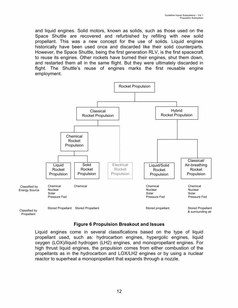
2.1 General Discussion Given the significant amount of thrust needed to obtain even sub-orbital altitudes, propulsion subsystems play a central role in any RLV’s design affecting overall vehicle weight, configuration, and flight characteristics. Primary propulsion is considered a safety-critical system as defined in the RLV licensing rule. This designation stems from both the high-energy nature of the Propulsion Subsystem and unknown hazards that may arise through the application of novel technology and fuels currently being considered for RLVs. In this document, the Propulsion Subsystem includes the main engines, reaction control thrusters, and orbit-maneuvering thrusters that may be used on-board an RLV. It should be noted that FAA/AST has not been assigned jurisdiction over on-orbit operations; however, orbit-maneuvering thrusters may have a role during reentry and descent and these flight phases are within FAA/AST jurisdiction. The propellants used in these systems are also considered safety critical elements. Considerations associated with propellant handling are addressed in Section 18.0 Propellant Management. Current rocket propulsion subsystems carry the propellant and oxidizer on-board for the entire mission; however, some propulsion systems may utilize the atmosphere as an oxidizer as is done on aircraft. Additionally, there may be hybrid propulsion systems that transition from “air breathing” to “rocket” propulsion or operate as a combination of both in the lower atmosphere, see Figure 6.
Rocket propulsion systems are categorized in two ways. The first is by the energy source; the second is by the propellant type. Propellants can be stored on-board or extracted from the surroundings. They may also be a generated source such as particle ejections. Energy sources are one of four types: stored (pressurized), chemical, nuclear, or solar.
Classical rocket propulsion systems are classified into two basic types: chemical propulsion systems and electric propulsion systems. Chemical systems are generally used for launch/takeoff, on-orbit maneuvering, and attitude control. Electric propulsion systems are being phased in for long term orbit maneuvering and attitude control. Currently these systems have much too low of thrust capability to provide the launch/takeoff lift capability and as such pose little to no public safety risk. However, their power source (e.g., nuclear) may pose public safety risks in the case of the breakup of the RLV over populated areas.
Within the chemical propulsion systems there are two main branches, as mentioned, that are described by their employment of propellant: solid motors
Guideline Inputs Subsystems – Vol 1 Propulsion Subsystem
12
and liquid engines. Solid motors, known as solids, such as those used on the Space Shuttle are recovered and refurbished by refilling with new solid propellant. This was a new concept for the use of solids. Liquid engines historically have been used once and discarded like their solid counterparts. However, the Space Shuttle, being the first generation RLV, is the first spacecraft to reuse its engines. Other rockets have burned their engines, shut them down, and restarted them all in the same flight. But they were ultimately discarded in flight. The Shuttle’s reuse of engines marks the first reusable engine employment.
Figure 6 Propulsion Breakout and Issues Liquid engines come in several classifications based on the type of liquid propellant used, such as: hydrocarbon engines, hypergolic engines, liquid oxygen (LOX)/liquid hydrogen (LH2) engines, and monopropellant engines. For high thrust liquid engines, the propulsion comes from either combustion of the propellants as in the hydrocarbon and LOX/LH2 engines or by using a nuclear reactor to superheat a monopropellant that expands through a nozzle.
Rocket Propulsion
Classical Rocket Propulsion
Hybrid Rocket Propulsion
Liquid/Solid Rocket
Propulsion
Classical/ Air-breathing
Rocket Propulsion
Electrical Rocket
Propulsion
Chemical Rocket
Propulsion
Liquid Rocket
Propulsion
Solid Rocket
Propulsion
Classified by Propellant
Classified by Energy Source
Chemical Chemical Chemical Chemical Nuclear Nuclear Nuclear Solar Solar Solar Pressure Fed Pressure Fed Pressure Fed
Stored Propellant Stored Propellant Stored propellant Stored Propellant & surrounding air

Guideline Inputs Subsystems – Vol 1 Propulsion Subsystem
13
2.2 Guideline Input Considerations
2.2.1 General The following Guideline Input Considerations have been identified for the Propulsion Subsystem:
Prop GIC - 1. System testing and checkout of engines and thrusters after maintenance should be conducted to ensure flight-worthiness criteria are met.
Prop GIC - 2. Engines should be vented of toxic fluids and gases for maintenance.
Prop GIC - 3. Engines should be secured to prevent contamination from foreign objects during maintenance.
Prop GIC - 4. Movement of engines and motors into position (e.g., mating with the RLV fuselage) should be conducted in accordance with the Operations Manual to ensure safety is maintained.
Prop GIC - 5. Mounting engines/motors to the RLV should ensure proper installation and alignment in order to maintain propulsion system reliability.
Prop GIC - 6. Test stand equipment connection and operation should be performed in such a way as to not cause damage or unsafe conditions to the propulsion system or any other vehicle system.
Prop GIC - 7. Pre-launch/takeoff engine and motor checklists should be performed in compliance with the Operations Manual of the RLV.
Prop GIC - 8. Engine combustion stability and motor burn status should be monitored for compliance with the RLV Operations Manual.
Prop GIC - 9. Interconnection with other subsystems (e.g., flight controls) should be tested after maintenance to ensure that it operates with the propulsion system while maintaining system reliability.
Prop GIC - 10. Engine performance and remaining useful life should be evaluated following each flight to account for engine wear characteristics.
Prop GIC - 11. Engines should be throttled according to Operations and Maintenance manuals.
Prop GIC - 12. Activation of the reaction control engines should maintain proper vehicle attitude control as required; this should be monitored in operation and verified after maintenance.

Guideline Inputs Subsystems – Vol 1 Propulsion Subsystem
14
Prop GIC - 13. Training for the Propulsion Subsystem should include power plant training, rocket/jet engine training, turbo-machinery training and On-the-Job-Training (OJT) at a minimum.
Prop GIC - 14. Check lists for normal as well as emergency Propulsion Subsystem situations should be subject to approval for operations.
Prop GIC - 15. Safety analysis conducted after any alteration to original design should include protection systems, backup/ redundant systems, reliability and calibration of tools, and human factors/work load considerations both during normal and contingency operations.
2.2.2 Inter/Intra Agency The following Propulsion Subsystem inter/intra agency considerations were identified: 1. Worker health and safety should be in compliance with OSHA regulations so
as not to introduce unsafe conditions on or near the vehicle during Propulsion Subsystem servicing and operations. Such conditions could be a causal factor in a larger accident resulting in a public safety issue.
2. Handling, transportation, and disposal of hazardous materials related to Propulsion Subsystem servicing and operations should be accomplished in compliance with Department of Transportation (DOT) Hazardous Material regulations so as not to lead to a public safety issue. Note that there may be related Environmental Protection Agency (EPA) regulations for this item as well.
3. The Department of Defense Explosive Safety Board (ESB) may provide a source of lessons learned for FAA/AST for conducting RLV safety evaluations.
Guideline Inputs Subsystems – Vol 1 Propulsion Subsystem
15
2.3 Guideline Recommendations
Prop GI - 1. Nozzle and Feed Line Crack Detection Guideline Input RLV engines and motors shall be inspected and repaired in compliance with the Maintenance Manual. Rationale An RLV requires the Propulsion Subsystem during nominal as well as contingency launch/takeoff and return operations. The Propulsion Subsystem employs nozzles and igniters for both engines and motors; propellant feed lines; and turbo-pumps for engines. These components may experience fatigue and failure more frequently or readily due to the extreme thermal and vibration environment in which they operate. In addition, the use of certain propellants such as hydrogen can lead to component embrittlement. When RLV liquid engines are maintained, the nozzle and feed lines must be checked for fatigue, cracks, and any non-nominal conditions must be repaired and restored to operational readiness in accordance with the RLV Operations Manual and RLV Maintenance Manual. The following items are examples of a minimum check:
1. Nozzle crack/fatigue (engines/motors) 2. Propellant feed line crack/fatigue (engines) 3. Turbo-pump crack/fatigue (engines) 4. Igniter anomalies (engines/motors)

Guideline Inputs Subsystems – Vol 1 Propulsion Subsystem
16
Prop GI - 2. Motor Operational Conditions Guideline Input RLVs that use solid rocket motors shall be operated in accordance with the Operations Manual to ensure compliance with thermal limits. Rationale One thermal issue for solid “case-bonded” rocket motors is the thermal interface between the cold grain and the hot case/hot grain liner. If the thermal limits are exceeded, this may cause bond-line tensile stress (i.e. tearing) and inner-bore surface cracking. The Space Shuttle Challenger accident is a prime example of a thermal limit “out of compliance” causing disastrous effects: the inability of the seal to quickly respond to the changing gap size during low temperature operating conditions is cited as one of the major causes for the joint failure between the sections of Challenger’s right solid rocket booster. This in turn allowed exhaust flames to leak through the joint and impinge upon the external fuel tank, eventually penetrating and igniting the fuel contained in the external tank, causing the explosion.2

Guideline Inputs Subsystems – Vol 1 Propulsion Subsystem
17
Prop GI - 3. Propulsion Subsystem Operational Conditions Guideline Input Propulsion Subsystems shall be operated only within the operating criteria specified in the Operations Manual. Rationale RLV developers/operators will have made certain assumptions regarding the operating conditions needed to safely operate their vehicle. Lessons-learned from the Space Shuttle Challenger indicate that certain designs have dependencies on the external operating environment. In the case of Challenger, this limitation turned out to be temperature. Other environmental considerations involve winds either at the launch site or at contingency airports, the presence of lightning in the launch area, etc. Since no single design will be employed by all RLV concepts under consideration, each RLV developer/operator needs to determine what the appropriate and safe operating conditions are for their vehicle.

Guideline Inputs Subsystems – Vol 1 Propulsion Subsystem
18
Prop GI - 4. Propulsion System Repair and Overhaul Guideline Input Propulsion System repair and overhaul shall return the motor to flightworthy condition per the Maintenance Manual. Rationale Current propulsion technologies often employ an extremely complex set of piping, valves, combustors/igniters, and gimbal actuators to perform engine control and combustion. The RLV developer/operator needs a clear and complete set of maintenance procedures for ensuring Propulsion Subsystem maintenance is done correctly.

Guideline Inputs Subsystems – Vol 1 Propulsion Subsystem
19
Prop GI - 5. Engine/Motor Ignition Guideline Input Ignition of engines and/or motors should be done in compliance with the Operations Manual of the RLV. Rationale Engine ignition must be done in accordance with the Operations Manual to ensure safe engine operations. For example, an improper ignition sequence could quickly cause excessive vibration force. This in turn may break the engine apart or cause excessive heat transfer that may melt engine components. During motor combustion the case expands and the grain compresses. Axial pressure differential is severe with end-burning grains. Critical areas of concern include grain fracture and grain de-bonding. Therefore, it is required that the motor ignition be conducted in accordance with the Operations Manual to ensure environmental and operational conditions are met for safe ignition.

Guideline Inputs Subsystems – Vol 1 Propulsion Subsystem
20
Prop GI - 6. Motor Refurbishment Guideline Input Motor refurbishment shall return the motor to flightworthy condition per the Maintenance Manual. Rationale Some RLV concepts will employ solid rocket motors. Motor refurbishment needs to be conducted to maintain the design specifications and to ensure reliability. While this technology is well known, motor refurbishment poses a potential safety risk to the public at the facility of refurbishment as well as a potential risk to the public during the flight of the refurbished motor.

Guideline Inputs Subsystems – Vol 1 Communications Subsystem
21
3.0 Communications Subsystem The Communications Subsystem is defined as the on-board hardware and software that provides the means to communicate vehicle/flight data and voice during all phases of O&M.
3.1 General Discussion A traditional space vehicle communication network is composed of both a ground infrastructure (e.g., telephones, cabling, and switches) as well as the on-board communication equipment. In addition, there are considerations of communication band usage (e.g., microwave, VHF, HF) and the potential reliance on other space-borne assets such as communication satellites. The information that is typically communicated includes mission/flight plans; telemetry about vehicle operating conditions and configurations; vehicle safety and crew health information; systems and payloads; commands to the vehicle systems to make them perform a function or configuration change; documentation from the ground (e.g., weather and conflict advisories) that is transmitted to the vehicle’s text and graphics system; video information; and voice communication among the flight crew members and between the flight crew and ground flight controllers. Since many forms of terrestrial communications may have insufficient range to support operations in the upper atmosphere and in space, new forms of communication may need to be developed for interaction with the existing ATC infrastructure. Communication for RLVs is likely to include the transmission of both voice and data for the purposes of flight planning, flight control, and air traffic management/control. Specifically, RLV communications may include the following:
1. Communication between the flight crew and traffic control personnel 2. Communication between the flight crew and the passengers/payload 3. Communication between the vehicle systems and the ground (health
and safety information, vehicle commanding, telemetry, attitude and orbit data, data from payload, etc.)
4. Communication between the flight crew (e.g., during extravehicular activities)
RLV on-board communication systems may include: 1. Software and hardware used to send commands from the ground 2. Software and hardware to process mission planning data (flight plans,
interface with flight management systems, processing of any commands from the ground)
3. Software and hardware to process vehicle health and safety data from health monitors and other sensors on-board, as well as attitude and orbit data

Guideline Inputs Subsystems – Vol 1 Communications Subsystem
22
4. Software and hardware to process telemetry from other sensor data from the vehicle to ground
5. Software and hardware used for payload and passenger management, and communication between payload/passenger and the crew
6. Software and hardware used to send and receive data from the ground 7. Software and hardware used to store data in cases of problems in
immediate transmission 8. Antenna - usually a wide-angle (hemispheric or omni directional); high
data rates may require directional antennas RLV communications are expected to make use of S, X, or Ku frequency bands, all of which have been approved for space use by international agreement. UHF VHF, C, Ka, and L bands may also be used.
3.2 Guideline Input Considerations
3.2.1 General The following are Guideline Input Considerations for the Communications Subsystem:
Comm GIC - 1. Supporting ground infrastructure should be able to receive, process, store (as needed), and send information to/from the RLV.
Comm GIC - 2. If the RLV communication system must communicate with ground stations in the existing Space Ground Link System (SGLS), then its transponder must be compatible with SGLS. Similar compatibility issues exist with the Tracking and Data Relay Satellite System (TDRSS).
Comm GIC - 3. Training for communication operations should be provided for both nominal and off-nominal scenarios and should involve all crew, both on the RLV and on the ground.
Comm GIC - 4. Approval Authority should be trained in communications systems (software and hardware) issues, and able to recognize inadequate verification and inadequate training.
Guideline Inputs Subsystems – Vol 1 Communications Subsystem
23
3.2.2 Inter/Intra Agency The following Communication Subsystem inter/intra agency considerations were identified: 1. The FAA Office of System Architecture and Investment Analysis (FAA/ASD)
is responsible for the planning, design, formulation, and evaluation of system improvements and interfaces for the National Airspace System (NAS).
2. Coordination with the International Telecommunications Union (ITU) and Federal Communications Commission (FCC) for radio spectrum allocation and usage should occur. The Federal Communications Commission (FCC) is an independent United States government agency, directly responsible to Congress. The FCC was established by the Communications Act of 1934 and is charged with regulating interstate and international communications by radio, television, wire, satellite and cable. The FCC's jurisdiction covers the 50 states, the District of Columbia, and U.S. possessions. The International Telecommunications Union (ITU) is headquartered in Geneva, Switzerland. ITU is an international organization within the United Nations System where governments and the private sector coordinate global telecom networks and services.

Guideline Inputs Subsystems – Vol 1 Communications Subsystem
24
3.3 Guideline Recommendations
Comm GI - 1. Communications Capability Guideline Input The RLV shall be equipped with at least one primary and one backup form of communications to be operated in accordance with the Operations Manual and capable of interfacing with Air Traffic Control and any required Mission Control. Rationale The National Airspace (NAS) is operated utilizing positive control, meaning that all airspace users (at RLV operating altitudes) are responsible for communicating and complying with directions provided by the governing Air Traffic Controller for the airspace being transited. While accommodations such as Special Use Airspace (SUA) and Temporary Flight Restrictions (TFR) are likely for RLV operations, Air Traffic Control must still be able to communicate with the RLV for the purposes of ensuring the public safety.

Guideline Inputs Subsystems – Vol 1 Communications Subsystem
25
Comm GI - 2. Communications Subsystem Maintenance, Test, and Checkout
Guideline Input Maintainer/technicians shall maintain, test, and checkout the Communications Subsystem following any maintenance/repair action on the subsystem. Rationale Given the importance of the Communications Subsystem, maintainers must be proficient in their tasks to not only diagnose/repair/restore the equipment, but also to operationally test the Communications Subsystem to ensure no problems were introduced during maintenance task. Maintainers will have the ability to:
1. Assess the correctness of the communication display data and format 2. Assess error messages 3. Perform corrective actions recommended in the manuals as well as on
the displays 4. Use of transmitters, receivers, and antennae 5. Perform link analysis 6. Perform end-to-end testing

Guideline Inputs Subsystems – Vol 1 Communications Subsystem
26
Comm GI - 3. Communications/NAS Integration Guideline Input Modes of communications used by an RLV for airspace traffic purposes shall ensure integration with NAS operations. Rationale The specific types of communications equipment along with the need for backup communications must be considered. There is also a need for a new terrestrial communications link between ATC and any RLV mission control. The introduction of RLV-related communications into the ATC infrastructure must be planned in such a way as to take advantage of the latest technology being fielded as part of the FAA’s modernization efforts.

Guideline Inputs Subsystems – Vol 1 Communications Subsystem
27
Comm GI - 4. Hazardous Communications Emissions Guideline Input For RF systems with hazardous emissions, an alternative to radiating during testing and maintenance (e.g., on-board test load and GSE port) shall be provided. Rationale
This will minimize radiation risks and enable safe testing and troubleshooting.
“Exposure limits for RF/MW radiation are designed to keep the RF/MW energy absorbed by the body well below the lowest levels associated with demonstrated adverse effects, and to reduce the likelihood of contact shocks and burns.
A limit on the rate at which RF electromagnetic energy is absorbed in the body, the specific absorption rate (SAR) expressed in watts/kg (of body mass); for example, the SAR limit averaged over the whole body mass is 0.4 W/kg.
In practice, the SAR can only be measured under laboratory conditions using models of the human body ("phantoms"); instead, limits are prescribed for the electric and magnetic fields, which can be measured. For RF/MW workers, the field limits incorporate a safety factor of 10 with reference to the scientific-consensus threshold for adverse health effects; for other persons including the general public, a further safety factor of 2 to 5 is included to arrive at lower limits.”3

Guideline Inputs Subsystems – Vol 1 Navigation/Guidance Subsystem
28
4.0 Navigation/Guidance Subsystem The Navigation/Guidance subsystem is defined as the on-board hardware and software that provides the means to compute the orientation and position of the vehicle with respect to either an inertial or a rotating reference system and uses this information to steer or maneuver in a targeted manner.
4.1 General Discussion Historically, spacecraft navigation and guidance has been performed on the ground because computation capability on-board was limited and the demand of space navigation sensor data analysis and subsequent guidance algorithms was too great. However, most of the commercial RLV concepts currently in development are based on an autonomous vehicle model similar to that employed in traditional aviation. The Navigation/Guidance Subsystem Guideline Inputs discussed here are intended to apply specifically to the on-board components associated with the provision of the vehicle’s navigation/guidance capability. A navigation system computes the orientation and position of the vehicle with respect to either an inertial or a rotating reference system. Specifically, it determines the Position, Velocity, Attitude (orientation of vehicle’s body axes relative to a particular coordinate system), and Time (PVAT, also known as the state vector) information relative to specified references. This computation requires three things: sensors to collect data, local (onboard) or ground computers to process the data, and mathematical algorithms (software) to interpret the data. The accuracy is usually limited by hardware quality and software performance. Traditionally, there have been three types of navigation systems employed: pilotage, celestial navigation, and deduced reconnaissance (dead reckoning). Pilotage is simply navigation based on the pilot’s skill or knowledge of geographic landmarks. Celestial navigation, a branch of applied astronomy, is the art and science of finding one's geographic position by using astronomical observations, particularly by measuring altitudes of celestial bodies – sun, moon, planets, or stars. Although celestial navigation is still used in higher earth orbiting spacecraft attitude control systems, satellite navigation systems (e.g., GPS) that are inexpensive and provide real-time position data to within a few meters are more common in low earth orbit. Dead reckoning is the approximation of present position based on adding incremental velocity vectors multiplied by the applicable time interval, to a previously determined position fix. Examples of dead reckoning systems are Inertial Measurement Units (IMUs), which integrate accelerometer outputs to obtain the velocity vector, multiply the velocity times the time interval since the last calculation and add it to the last “known” position. The three basic hardware

Guideline Inputs Subsystems – Vol 1 Navigation/Guidance Subsystem
29
components of any inertial navigation system are a platform oriented with rate sensors; accelerometers to supply specific components of acceleration; and a computer that integrates the signals from the sensors. The guidance system uses navigation information to steer, or maneuver, in a targeted manner. This is accomplished by propagating the current state vector of the vehicle forward in time to predict its future behavior and compare it to the desired profile. Guidance systems use mathematical models of the environmental torques and forces, vehicle dynamics models, and algorithms to propagate the current state. The limiting factors are the knowledge of the self-induced torques/forces (control hardware) and environmental torques/forces, and accuracy of the mathematical models of vehicle dynamics. Guidance systems are typically programmed in advance of a mission with the intended trajectory and desired attitude profile that will satisfy all the mission requirements. This programming will cause the vehicle’s propulsion and attitude actuators to fire at the proper time and at the proper orientation in order to achieve the desired profile. If circumstances change or an error is found, then either on-board systems or ground controllers compute the state of the spacecraft at the time in question and compare that to the desired state. The new propulsion and attitude actuator commands are then executed to respond to the off-nominal situation. For unmanned RLV, ground-based guidance will likely be required to ensure public safety. Guidance systems interact with a variety of other on-board systems including communications, flight controls, and propulsion. In the case of an on-board autonomous integrated inertial navigation/guidance system, inertial attitude and velocity data is provided to the guidance navigation and control avionics and the vehicle’s state vector is derived. Guidance software uses the attitude data, along with state vector, to develop steering commands for the flight control system. The flight control system then uses the attitude data from the inertial system to convert the steering commands into control surface commands, and Thrust Vector Control (TVC)/ Reaction Control System (RCS) thruster fire commands. It is likely that the majority of vehicle designs now being formulated will make use of the Global Positioning System (GPS) to determine position and velocity. This system was designed for Earth navigation but can be used for vehicles in LEO (Low Earth Orbit) as well; however, GPS only outputs position, velocity and time; it does not provide any type of attitude data. GPS position, velocity and time data are very accurate, however, the update rate is not sufficient for most applications. Therefore, GPS is often used to compensate for IMU drift by providing accurate update to the IMU “starting point”. Figure 7 illustrates the functions associated with this type of an integrated navigation/guidance subsystem, and Table 1 highlights error sources/magnitudes

Guideline Inputs Subsystems – Vol 1 Navigation/Guidance Subsystem
30
associated with different subsystem elements. For the GPS component of the system, the potential for error is reported to be approximately 1500 feet (3-sigma) for a system without differential correction, and 300 feet (3-sigma) for a differential GPS receiver.4 Additionally, although GPS receivers have been found to be relatively resistant to jamming, and have demonstrated the ability to maintain lock on the satellite signals at accelerations significantly higher than those expected during booster flight of space launch vehicles, they do experience momentary loss of signals resulting from staging or other dynamic events.
Figure 7 Navigation and Guidance Flow
Table 1 Navigation and Guidance Error Sources5
NAVIGATION Error Source 3-σ Magnitude
GUIDANCE Error Source 3-σ Magnitude
Gyro Drift .7 degrees/hour Thrust Dispersions 1.5 sec Gyro Scale Factor 200 ppm Vehicle Dry Weight Dispersions 2 lbs Gyro Input Axis Misalignment 90 arc sec Thrust Vector Misalignment .1 deg Sensitivity to Acceleration .7degrees/hr/g Aerodynamic Coefficient Dispersions +/- 5% variation Gyro Noise .5 arc sec Wind Dispersions Varies Accelerometer Bias 200 µ-g Atmospheric Dispersions Varies Accelerometer Scale Factor 300 ppm Open Loop Initial Attitude Error 180 arc sec Accelerometer Input Axis Misalignment 90 arc sec Accelerometer Noise .002 ft/sec IMU Location Uncertainty .25 in Initial State Error 3 * RSS
IMU Acceleration and
Attitude Data
GPS Position and Velocity
Data
Navigation Position, Velocity and Attitude
Determination
Guidance Control Command
Determination
Guidance/Control Steering Interface
Desired Vehicle Velocity Desired Vehicle Attitude

Guideline Inputs Subsystems – Vol 1 Navigation/Guidance Subsystem
31
4.2 Guideline Input Considerations
4.2.1 General The following Guideline Input Considerations have been identified for the Navigation/Guidance Subsystem:
Nav GIC - 1. Precision instrumentation should be maintained with the use of calibrated instrumentation and tools during maintenance.
Nav GIC - 2. Maintainers should be adequately trained to assess the a. Correctness of the displays of individual sensors b. Correctness of the displays of data fusion from different
sensors c. Error messages d. Corrective actions recommended in the manuals as well
as on the displays Nav GIC - 3. Approval Authority should be trained in navigation and
guidance systems (software and hardware) issues, and able to recognize inadequate verification and inadequate training.
4.2.2 Inter/Intra Agency The following Navigation/Guidance Subsystem inter/intra agency considerations were identified: 1. The FAA Satellite Navigation Product Team is responsible for the planning,
design, formulation, and evaluation of system improvements and interfaces for the National Airspace System (NAS).
2. There should be a function for space traffic similar to that of the International Civil Aviation Organization (ICAO). Presently, the State Department is instrumental in coordinating overflight of foreign countries. However, there is need for a unifying influence, in certain areas, for the development of a code of international space traffic law. It is a function of ICAO to facilitate the adoption of international air law instruments and to promote their general acceptance. So far international air law instruments have been adopted under the Organization's auspices involving such varied subjects as the international recognition of property rights in aircraft, damage done by aircraft to third parties on the surface, the liability of the air carrier to its passengers, crimes committed on-board aircraft, marking of plastic explosives for detection and unlawful interference with civil aviation.
3. United Nations Office for Outer Space Affairs (UNOOSA) is the United Nations office responsible for promoting international cooperation in the peaceful uses of outer space. In particular, on behalf of the Secretary-General, UNOOSA maintains the Register of Objects Launched into Outer Space.

Guideline Inputs Subsystems – Vol 1 Navigation/Guidance Subsystem
32
4.3 Guideline Recommendations
Nav/Guidance GI - 1. GPS-Based Navigation/Guidance Subsystem Guideline Input If a GPS-based navigation/guidance subsystem is utilized, then the navigation/ guidance subsystem shall be augmented by a secondary on-board position, velocity, and attitude determination subsystem. Rationale Guidance software requires position, velocity, and attitude data to develop steering commands for the flight control subsystem. GPS position, velocity, and time data are very accurate; the potential for error is reported to be approximately 1500 feet (3-sigma) for a system without differential correction, and 300 feet (3-sigma) for a differential GPS receiver.6 However, GPS does not provide attitude information. Additionally, vehicles may experience momentary loss of GPS signals during staging or other dynamic events. Consequently, it is necessary to augment a GPS-based subsystem with a secondary on-board position, velocity, and attitude determination subsystem. GPS receivers have been found to be relatively resistant to jamming, and have demonstrated the ability to maintain lock on the satellite signals at accelerations significantly higher than those expected during booster flight of space launch vehicles. An Inertial Measurement Unit (IMU) is an example of a secondary on-board velocity and attitude determination subsystem. IMUs provide inertial attitude and velocity data for use by the navigation/guidance software. This software uses the IMU data to determine the vehicle’s state vector (i.e. position and velocity) and then develops steering commands for the flight control system using the IMU attitude data along with the state vector.
Guideline Inputs Subsystems – Vol 1 Navigation/Guidance Subsystem
33
Nav/Guidance GI - 2. Inertial Navigation/Guidance Subsystem Guideline Input If an inertial navigation/guidance subsystem is used, it shall be calibrated periodically against a highly accurate position source. Rationale Guidance software requires position, velocity, and attitude data to develop steering commands for the flight control subsystem. An inertial navigation/guidance subsystem provides inertial attitude and velocity data that is used to determine the vehicle’s state vector. Guidance software uses the attitude data, along with state vector, to develop steering commands for the flight control system. The flight control system then uses the attitude data from the inertial system to convert the steering commands into control surface commands, and Thrust Vector Control (TVC)/ Reaction Control System (RCS) thruster fire commands. A star tracker sensor system or a GPS-based system with an augmentation correction signal such as the Wide Area Augmentation System (WAAS) are examples of highly accurate position sources that may be used to provide the required calibration.

Guideline Inputs Subsystems – Vol 1 Navigation/Guidance Subsystem
34
Nav/Guidance GI - 3. Navigation/Guidance Sensor Calibration Guideline Input Following any Navigation/Guidance Subsystem maintenance actions, all Navigation/ Guidance Subsystem sensors shall be recalibrated in accordance with the Maintenance Manual. Rationale Accurate position/velocity/attitude data is imperative to developing correct flight control commands. In order to minimize the chance of sensor inaccuracies propagating to flight control commands, the sensors must be recalibrated whenever any maintenance/repair activities may have directly or indirectly affected their alignment. Incorrect flight control commands could impact both Air Traffic Management and create the potential for object collision (e.g., COLA and COMBO).
Guideline Inputs Subsystems – Vol 1 Avionics Subsystem
35
5.0 Avionics Subsystem The Avionics Subsystem is broadly defined to include the electronics associated with all on-board systems.
5.1 General Discussion Avionics systems control or assist in controlling most of the RLV functions including vehicle status and operational readiness, performance monitoring, and data processing for many other subsystems including communications, guidance, navigation, environmental, and flight controls. For instance the Space Shuttle avionics system controls, or assists in controlling, most of the shuttle subsystems. The Shuttle avionics are designed to handle multiple failures through redundant hardware and software that are managed by the complex of five computers. The Shuttle program calls this a fail-operational/fail-safe capability. Fail-operational performance means that, after one failure in a subsystem, redundancy management allows the vehicle to continue on its flight. Fail-safe means that after a second failure, the vehicle still is capable of returning to a landing site safely.7 Modern avionics are almost all digitally based. Avionics computer architectures may be centralized, federated or distributed. A variety of military and commercial standards (e.g., Aeronautical Radio, Inc. - ARINC) exist for each of these architectures.
5.2 Guideline Input Considerations
5.2.1 General The following Guideline Input Considerations have been identified for the Avionics Subsystem:
Avionics GIC - 1. Operational procedures should be written to take advantage of any reduced modes allowed for in the Avionics Subsystem so as to maximize vehicle capability in off-nominal situations and to ensure the most necessary functions are kept in operation while troubleshooting and repair tasks are performed.
Avionics GIC - 2. Maintenance procedures for checkout and approval of avionics on-board the vehicle should include procedures for safing the vehicle.
Avionics GIC - 3. Any software or hardware tools used to maintain avionics and which have the opportunity to introduce errors should be evaluated for correct operation and calibrated where needed.
Avionics GIC - 4. Software within avionics should be tested for resource management and deconfliction with proper priority
Guideline Inputs Subsystems – Vol 1 Avionics Subsystem
36
between different functions (time, data access, memory, display panels, etc.)
5.2.2 Inter/Intra Agency No Avionics Subsystem inter/intra agency considerations were identified.

Guideline Inputs Subsystems – Vol 1 Avionics Subsystem
37
5.3 Guideline Recommendations
Avionics GI - 1. Avionics Out-of-Configuration Guideline Input Out-of-configuration Avionics Subsystem conditions shall be recognized and isolated upon activation. Rationale It is often required for hazardous or critical operations to know if a system’s electrical configuration is operational. An actuator is expected to have at least one channel of control. If no channels are connected, there is no control of the actuator. As an example of this issue8, note that the rudder/speed brake was once powered up hydraulically on the Shuttle Orbiter without knowledge that the command path connections were demated for troubleshooting, thus there was no direct connection with the associated actuator control. As a result, there was damage to the actuator. This could be disastrous if a gimballing engine is moved in an uncontrolled manner. This poses a safety hazard to personnel, the vehicle and possibly the public.

Guideline Inputs Subsystems – Vol 1 Flight Control Subsystem
38
6.0 Flight Control Subsystem The Flight Control Subsystem is defined as the software and hardware necessary to move a vehicle in the desired orientation and/or direction commanded by the Navigation/Guidance Subsystem.
6.1 General Discussion Flight control includes translational motion (firing engines to move the vehicle to a desired flight path), attitude stabilization (maintaining the attitude in a desired state), and attitude maneuvering (changing the attitude from one orientation to another about the vehicle’s body axes – roll, pitch and yaw). These processes involve the use of flight control hardware to include propulsive engines, reaction control jets, and aerodynamic control surfaces (such as flaps, ailerons and their associated actuators). Additionally, flight control utilizes on-board and/or remote computers, and relevant software, to generate commands (e.g., how long to fire the thrusters and degree of movement of flaps). Some RLVs, (e.g., winged vehicles), will utilize control surfaces, similar to aircraft control surfaces, as well as reaction control systems that conventional spacecraft use. On these vehicles, flight control will transition from using aerodynamic surfaces for control to reaction control mechanisms at the point when aerodynamic control surfaces no longer function due to insufficient dynamic pressure. RLV concepts vary on the implementation of these controls and the associated transition between these two methods. However, several of the current RLV concepts will only attain sub-orbital altitudes where transitional flight control is likely to be of concern. There are three scenarios for commanding the vehicle control surfaces/devices: autonomous commanding, piloting on-board the vehicle, or ground-controlling the vehicle. In all cases the process for determining the required commands is the same: Guidance software uses the attitude and state vector data provided by the Navigation/Guidance Subsystem to develop steering commands for flight control. The Flight Control Subsystem uses the attitude data to convert the steering commands into control surface movement, and/or TVC/RCS thruster fire commands. Although the command planning/generation process is unchanged, there is an added complexity and additional hardware components for a ground-based commanding capability due to the additional communication infrastructure and the “human in the loop”. Modern flight controls are calibrated for a particular vehicle’s flight characteristics and weight distribution. The flight control computers typically compensate for changes in the vehicle configuration during flight such as staging or the shifting of the center of gravity due to consumption of on-board propellants. For the Space Shuttle, much of the flight control calculations are still manually accomplished on the ground prior to launch. Most of the RLV concepts under consideration use automated systems similar to modern aircraft; however, some RLV concepts are exploring “self-learning” neural networks to perform flight control calculations.

Guideline Inputs Subsystems – Vol 1 Flight Control Subsystem
39
6.2 Guideline Input Considerations
6.2.1 General The following Guideline Input Considerations have been identified for the Flight Controls Subsystem:
Flt Ctrl GIC - 1. The impact of thrust vector misalignments on operations should be assessed/minimized since this condition can cause major inefficiencies and errors.
Flt Ctrl GIC - 2. If fuzzy logic is employed in the development of control commands/algorithms, then IEC 1131-7 or an equivalent standard should be followed for maintenance of the logic.
6.2.2 Inter/Intra Agency No Flight Control Subsystem inter/intra agency considerations were identified.

Guideline Inputs Subsystems – Vol 1 Flight Control Subsystem
40
6.3 Guideline Recommendations
Flight Controls GI - 1. Flight Control Post Maintenance Inspection and Testing
Guideline Input Flight Control Subsystems shall undergo a post-maintenance inspection and testing following any repairs or alterations to wiring or physical interconnections, to verify proper operation. Rationale Incorrect reconnection of flight control components has been the root cause of many commercial and military crashes. Often such errors have led to flight controls acting in an opposite fashion to the original design and opposite of what the pilot is expecting.

Guideline Inputs Subsystems – Vol 1 Flight Control Subsystem
41
Flight Controls GI - 2. Flight Control Subsystem Actuators Guideline Input Equipment shall be checked and repaired for conditions that can cause loss of functionality of actuators that control flight prior to each flight per the Maintenance Manual. Rationale Actuators that move the aerodynamic control surfaces may be pneumatic, hydraulic, or electromechanical. Since the functionality of actuators is a flight essential function, checks need to include that the actuators are functioning properly. These checks will be different for different types of actuators. For example if actuators are powered by hydraulics, checks need to include fluid leaks that can result in loss of power.

Guideline Inputs Subsystems – Vol 1 Flight Control Subsystem
42
Flight Controls GI - 3. Flight Control Algorithm Modifications Guideline Input Changes to flight control algorithms shall be operationally validated and maintained under configuration control. Rationale The Flight Control System is one of the most safety critical systems on-board the RLV. Any modifications to the algorithms that determine the commands that will be sent to alter the course of the vehicle must be validated and completely traceable. The traceability function serves a dual purpose. It makes it possible to evaluate the impact of a change to the overall system and controls the change as it is being made. With configuration control in place, there is less chance of making undesirable changes to a system that may later adversely affect the flight safety of the RLV.

Guideline Inputs Subsystems – Vol 1 Thermal Protection Subsystem
43
7.0 Thermal Protection Subsystem The Thermal Protection Subsystem (TPS) provides protection to the vehicle and the crew from external temperature extremes: the heat that is generated as the RLV traverses through the atmosphere during launch/takeoff/reentry and protection from the cold while on-orbit.
7.1 General Discussion Thermal protection is an area that is unique to space flight and certain hypersonic aircraft. Mercury, Gemini, and Apollo all employed an ablative TPS (during reentry the material burned away as the capsules reentered the atmosphere). The Space Shuttle utilizes a variety of materials in its TPS, including reinforced carbon-carbon (RCC), an advanced flexible reusable surface composite insulation and reusable/non-ablative ceramic tile materials. TPS does not have a clear corollary in traditional aviation and will require an evolving regulatory position because significant research is underway in this area. Failure of TPS may result in a catastrophic failure of the vehicle resulting in the loss of vehicle, loss of life on-board, and ground hazards/damage due to debris as witnessed during the recent Space Shuttle Columbia accident9. Figure 8 illustrates three types of Thermal Protection Subsystems:
1. Passive (radiation/conduction material properties are employed) 2. Semi-passive (e.g., ablative shielding) 3. Active (such as the 20 gal of water are carried aboard the SR-71 aircraft
for cooling of electronics and instrumentation10) The figure also depicts different types of heat transfer mechanisms that have been used in these systems. Safety issues during operation and maintenance are dependent on whether the system is passive, semi-passive or active and the kind of heat transfer used in that type of system.

Guideline Inputs Subsystems – Vol 1 Thermal Protection Subsystem
44
Figure 8 Types of Thermal Protection Systems11
7.2 Guideline Input Considerations
7.2.1 General The following Guideline Input Considerations have been identified for the Thermal Protection Subsystem:
Thermal GIC - 1. If a material of different fatigue life is introduced in replacement and sparing then Routine Maintenance should ensure the design is not compromised.
Thermal GIC - 2. TPS maintenance cycles should be adjusted based on inspection data (i.e. more frequent maintenance for an increased incidence of problems found).
Thermal GIC - 3. Maintainers should be trained to accurately conduct TPS testing and interpret test results from non-destructive methods such as pulse echo ultrasonic inspection, pulsed infrared thermograph, optical inspection etc.
Insulated Structure
PASSIVE:
Surface Heating
Heat Sink Structure
Radiation
Hot Structure
Surface HeatingRadiation
Surface Heating Radiation
Conduction
INSULATION
STRUCTURE
SEMI-PASSIVE Working Fluid
Surface Heating
Radiation
Heat PipeABLATION
ACTIVE
STRUCTURE
ABLATOR
Surface Heating
Air Flow
Coolant Flow
Surface Heating
Air Flow
Transpirational Cooling
CoolantFlow
Surface Heating
Air Flow
FilmCooling
ConvectiveCooling
CoolantFlow
Surface Heating
Reflection
Guideline Inputs Subsystems – Vol 1 Thermal Protection Subsystem
45
Thermal GIC - 4. Maintainers should be trained in special material properties that may be required for TPS functionality.
Thermal GIC - 5. Maintenance procedures (possibly including visual inspections, NDE (non-destructive evaluation), and on-board health monitoring data) should include procedures for evaluating the TPS operating characteristics (nominal and emergency operating ranges) following each flight including:
a. Material integrity b. Presence of leaks in active and semi-passive
systems
The TPS was damaged during the ascent of the Space Shuttle Columbia on the flight of STS-113. This damage ultimately led to the loss of the vehicle and the distribution of debris over a wide area of the United States from California to Texas and Louisiana. The following recommendations are derived from the recommendations of the Columbia Accident Investigation Board12:
Thermal GIC - 6. Normal vehicle operation should not result in the shedding of any materials (e.g., insulation) that could damage the TPS of the vehicle.
Thermal GIC - 7. Proper precautions should be taken to ensure reactive agents that could damage materials used to provide TPS capability are kept away from the vehicle during operations and maintenance (e.g., zinc primer degrades carbon-carbon components).
7.2.2 Inter/Intra Agency No Thermal Protection Subsystem inter/intra agency considerations were identified.

Guideline Inputs Subsystems – Vol 1 Thermal Protection Subsystem
46
7.3 Guideline Recommendations
Thermal Protection GI - 1. TPS Capability Guideline Input The RLV Thermal Protection System shall be operated within the temperature ranges expected during the vehicle’s flight. Rationale As demonstrated by the loss of the Columbia, once a TPS is compromised, it can quickly lead to a subsequent breakup during reentry. The resulting debris field can be dispersed over a large area with a high likelihood of property damage and the potential for loss of life if the breakup happens over a populated area. Although there were no reported injuries on the ground from the debris of Columbia, the results could have been considerably different had the breakup occurred earlier. A study performed by ACTA, Inc. stated that “had Columbia broken up less than a minute earlier, more than 40 tons of wreckage then would have fallen on the southern suburbs of the Dallas-Fort Worth area”, instead of rural Texas. "The result, in this case, was an increase in the calculated risk to the public by about 36 percent".13

Guideline Inputs Subsystems – Vol 1 Thermal Protection Subsystem
47
Thermal Protection GI - 2. TPS Inspections Guideline Input Inspection and repair shall be performed to prevent the loss of TPS functionality prior to each flight in accordance with the Maintenance Manual. Rationale During turnaround maintenance activities on an active TPS the following items should be verified:
1. Coolant or other materials used are still operationally viable after being exposed to extreme conditions (temperature and pressure).
2. Coolant circulation and ejection systems are fully functional. 3. Protective surfaces are free of fractures.
TPS has to function in an extremely hostile environment. Minor details can be exaggerated in this environment to cause a mishap. Inspections need to include effects of rain erosion, space debris and micrometeorites, gaps from thermal effects, deflections of the airframe, material changes from extreme temperatures, loosened parts from vibration, melting, deformation (especially at leading edges of wings and nose cone), tears, frays and breaks in fabrics, integrity of bonding materials, gap fillers and adhesives, tool drop, landing mishaps. Inspections need to take advantage of advanced non-destructive inspection technology. Temperature history during reentry from sensors in subsurface may be used as warnings for impending failure. The Columbia Investigation Recommendation R3.2-1 applies to this Guideline Input: “Initiate an aggressive program to eliminate all External Tank Thermal Protection System debris-shedding at the source with particular emphasis on the region where the bipod struts attach to the External Tank.”14

Guideline Inputs Subsystems – Vol 1 Thermal Protection Subsystem
48
Thermal Protection GI - 3. Management Safeguards for TPS Guideline Input Management safeguards shall be in place to ensure any hard to obtain or expensive materials used in TPS maintenance are available in sufficient quantities so as to avoid external pressures relating to cost, schedule, or other non-relevant considerations relating to return to flight. Rationale The TPS was damaged during the ascent of the Space Shuttle Columbia. This damage ultimately led to the loss of the vehicle and the distribution of debris over a wide area in Texas. This recommendation is derived from the recommendations of the Columbia Accident Investigation Board15.
Guideline Inputs Subsystems – Vol 1 Electrical/Wiring Subsystem
49
8.0 Electrical/Wiring Subsystem The Electrical and Wiring Subsystem is defined as the hardware required for all on-board generation of data distribution wiring, electrical power, power distribution, and emergency power provision.
8.1 General Discussion Figure 9 illustrates the general power functions of an RLV or any spacecraft. Power generation is accomplished in a variety of ways including batteries, conventional aircraft engine-mounted generators, on-board Auxiliary Power Units (APUs) and fuel cells as used on the Space Shuttle, Ram Air Turbines (RATs), and Radioisotope Thermoelectric Generators (RTGs) similar to those found on the Cassini spacecraft. Some of these sources are only available in the sensible atmosphere. For extended on-orbit operations, solar power generation may also be an option. The fuel source used for power generation is generally the area of concern relative to public safety. For example: the Shuttle APUs use hydrazine which is a volatile, toxic and caustic fuel; similarly, fuel cells use hydrogen which must be handled correctly to ensure public safety (e.g., hydrogen leak detection sensors and pressure control to ensure safe operation); and RTGs must be monitored for plutonium radiation leaks. There are more than 300 miles of wiring on-board the Shuttle and the whole fleet was grounded during 1999 for electrical wiring inspections. Technicians discovered that an exposed wire caused a short circuit that knocked out two engine computers16. A number of problems were caused by cramped spaces in which maintainers stepped on or accidentally damaged wiring/insulation while working on other parts of the Shuttle. Generally, the major safety issues associated with wiring relate to wire chafing, insulation degradation, and toxicity of insulation materials when overheated or burning. For example, the Shuttle has had issues with insulation degradation due to out-gassing of materials and the temperature extremes experienced in space flight. Finally, arcing resulting from worn contacts static buildup can present an ignition source for an on-board explosion in the presence of free hydrogen or vapor fumes from conventional aviation fuels.

Guideline Inputs Subsystems – Vol 1 Electrical/Wiring Subsystem
50
Figure 9 Power Functions17
8.2 Guideline Input Considerations
8.2.1 General The following Guideline Input Considerations have been identified for the Electrical/Wiring Subsystem:
Electric GIC - 1. Environmental testing for any new materials (e.g., electrical tape) used in maintenance should include vibration, temperature, and pressure extremes, exposure to charged particles (especially for printed circuit boards and complex electronic hardware), and thermal/vacuum chamber testing.
Electric GIC - 2. When using hot-stamp marking machines for wire identification, maintainers should be trained in the correct use of these devices. If used incorrectly, these marking machines may damage a wire’s insulation.
While not directly indicted as a cause of the Columbia accident, the Columbia Accident Investigation Board noted that wiring issues were a significant risk item for the Shuttle, particularly in light of the efforts to extend the Shuttle’s service life. The following Guideline Input Consideration resulted from recommendations in the Board’s final report:18
Electric GIC - 3. RLVs developer/operators should make every effort to develop a maintenance approach that allows for 100% inspection of all vehicle wiring, even that which is not directly accessible.
Power Source
Source Control
Power Management & Distribution
Power Processors
Load
Energy Storage Control
Energy Storage
Power Source Solar photovoltaic Radio-isotope thermoelectric generator
Nuclear reactor Fuel Cells Solar dynamic Primary batteries
Source Control Shunt regulator Series regulator Shorting switch array
Power Conditioning DC-DC converters DC-AC inverters Regulators
Energy Storage Control
Charger Regulator
Energy Storage
Batteries Flywheels

Guideline Inputs Subsystems – Vol 1 Electrical/Wiring Subsystem
51
8.2.2 Inter/Intra Agency The following Electrical /Wiring Subsystem inter/intra agency considerations were identified: 1. The US Department of Energy (DOE) provides nuclear power source
materials and is responsible for the safety testing and analysis associated with their planned use. The Presidential Directive NC/25 established the Interagency Nuclear Safety Review Panel (INSRP) that conducts an independent review of each proposed mission, prior to launch.

Guideline Inputs Subsystems – Vol 1 Electrical/Wiring Subsystem
52
8.3 Guideline Recommendations
Electrical/Wiring GI - 1. RLV Electrical/Wiring Subsystem Inspection
Guideline Input The RLV Electrical/Wiring Subsystem shall be inspected, and, if needed, promptly repaired in compliance with the Maintenance Manual. Rationale A failure in the Electrical/Wiring Subsystem could potentially cause a catastrophic failure of the RLV. The Electrical/Wiring Subsystem interacts with nearly all other subsystems aboard the RLV as well as ground support equipment and facilities. The Electrical/Wiring Subsystem can be evaluated in a number of ways, including visual inspection (for damaged/cracked/deteriorated insulation), impedance testing (e.g., checking for degradation of the data line), continuity testing and health monitoring of connected systems. The Air Transport Association (ATA) has identified the following inspection locations for transport aircraft. While not directly applicable to an RLV this list provides insight into traditional problem areas.
1. Engine, Pylon, and Nacelle Area: These areas are exposed to high vibration, heat, chemicals and frequent maintenance.
2. APU: Also exposed to high vibration, heat, chemicals and frequent maintenance.
3. Landing gear and wheel wells: These areas are exposed to severe external environment, vibrations and chemical contamination.
4. Electrical panels and LRUs are affected by disturbances, wire damage and insulation damage because of high instances of troubleshooting activities, refurbishment and maintenance.
5. Batteries: Wires in nearby areas should be inspected frequently for damage from chemical corrosion.
6. Power feeder terminations are prone to damage.

Guideline Inputs Subsystems – Vol 1 Electrical/Wiring Subsystem
53
Electrical/Wiring GI - 2. Wiring Damage Risk Mitigation Guideline Input Operations and Maintenance procedures shall include the following instructions:
1. Minimize working in or stepping across areas where wiring access panels are removed or wires are exposed.
2. During structural repairs, prevent swarf (sharp metal shavings and other objects) from falling into wire harnesses.
3. Do not allow panels and equipment to hang from their wiring connections.
4. Do not expose wires to fluids and environmental conditions for which the insulation materials have not been approved.
5. Do not introduce sharp bends in wires. Rationale Both the aviation and space launch communities have experienced serious ramifications due to problems in the area of wiring and electrical components: The Shuttle fleet was grounded during 1999 for electrical wiring issues. Cramped spaces in which maintainers stepped on or accidentally damaged wiring/insulation while working on other parts of the Shuttle were cited as causes for the problems. Within the aviation community, on 11 May 96, a “Valujet 592 crashes – anonymous witness tells the FAA the plane was notorious for bad wiring – 110 lives lost – the wiring on this 27 year old plane wouldn’t even pass the FAA’s only test for wire flammability.”19
Guideline Inputs Subsystems – Vol 1 Electrical/Wiring Subsystem
54
Electrical/Wiring GI - 3. Wiring Harness Integrity Guideline Input If string bindings or cable ties are removed during maintenance/repair activities, maintenance procedures and inspection checklists shall ensure that such items are replaced in accordance with schematic/structural drawings and specifications. Rationale The structural integrity of the wiring harness depends on these bindings/ties. If a wiring harness does not provide sufficient support to the wires, their insulation may crack/chafe and a short circuit could result. This was illustrated in the grounding of the Space Shuttle fleet in 1999, where an exposed wire caused a short circuit that took two engine computers off-line.

Guideline Inputs Subsystems – Vol 1 Software Subsystem
55
9.0 Software Subsystem The Software Subsystem is defined as any programmed computer language used to direct computers to perform desired functions in on-board Avionics Subsystems.
9.1 General Discussion There are three basic types of software20:
1. System software (operating system software) - programs that manage a computer’s basic tasks.
2. Utility software - programs that perform routine day-to-day tasks (e.g., compressing data, copying files, etc).
3. Application software - performs specialized functions like Space Shuttle control or other useful work not related directly to the operation of the computer itself.
For traditional aviation, the FAA requires specific conformity inspections for all safety-related software on-board aircraft.21 Safety-critical control subsystems are likely to contain or interface with software. Additionally, although structures, hydraulics, and thermal protection systems tend to be mechanical, they are likely to be monitored via a software-driven health monitoring system. Software can fail in spite of rigorous testing. Testing may or may not uncover underlying software errors. Furthermore, the space environment can cause single event upsets (a phenomenon that occurs to high-density electronics when subjected to radiation fields) that result in abnormal functioning of hardware and subsequently software. Abnormal functioning of software may give wrong (unexpected) results with or without indication that it has failed. The lack of indication and notification is dependent upon the error handling built into the software design. Failures without indication can lead to erroneous data used in critical decision making processes. It should be noted that the Space Shuttle employs both a Primary Avionics Software System (PASS) and a Backup Flight Systems (BFS), two completely independent software systems each capable of flying the Shuttle. To date, the BFS has never been used during a Shuttle mission22. The software in both of these systems was developed and verified to some of the most strict software standards employed anywhere in the world.
9.2 Guideline Input Considerations
9.2.1 General The following Guideline Input Considerations have been identified for the Software Subsystem:
Software GIC 1. Software modifications should comply with industry standard software engineering practices23 to prevent

Guideline Inputs Subsystems – Vol 1 Software Subsystem
56
inefficient performance and software aging problems that can lead to safety problems.
Software GIC 2. All modifications should be analyzed at the system level due to hardware modifications requiring software updates to be performed (and vice versa).
Software GIC 3. When modifications are made, requirements, specification, and design documentation should be updated to reflect the modifications.
Software GIC 4. Modifications should be verified to function as intended as well as to ensure that other system functions were not affected.
Software GIC 5. Maintainers should be familiar with software engineering, design and implementation, use of tools, verification activities, and an understanding of requirement specifications.
Software GIC 6. If software was designed to allow modification in flight, the flight crew and/or the ground flight controllers should be trained in the methods for such modification and any limitations to the extent of modification.
9.2.2 Inter/Intra Agency The following Software Subsystem inter/intra agency considerations were identified: 1. The Radio Technical Commission for Aeronautics (RTCA) is a private, not-
for-profit corporation that develops consensus-based standards regarding communications, navigation, surveillance, and air traffic management (CNS/ATM) system issues. In particular, the RTCA has published the following Guidelines/Standards in the area of software:
a. DO-278 Guidelines for Communication, Navigation, Surveillance, and Air Traffic Management (CNA/ATM) Systems Software Integrity Assurance Issued 3-5-02 - Prepared by SC-190/EUROCAE WG-52
b. DO-248B Final Annual Report For Clarification Of DO-178B “Software Considerations In Airborne Systems And Equipment Certification”, Issued 10-12-01 - Prepared by SC-190/EUROCAE WG-52
c. DO-178B Software Considerations in Airborne Systems and Equipment Certification Issued 12-1-92 - Prepared by SC-167 Supersedes DO-178A Advisory Circular Errata Issued 3-26-99
2. FAA Office of Aviation Research for their work in the software certification arena.
3. Institute of Electrical and Electronics Engineers, Inc. (IEEE) Standards Association – (e.g., IEEE 1228 – Standard for Software Safety Plan - applies to the software safety plan used for the development, procurement, maintenance, and retirement of safety-critical software).

Guideline Inputs Subsystems – Vol 1 Software Subsystem
57
9.3 Guideline Recommendations
Software GI - 1. Safety Critical Software Assurance Guideline Input RLV launch control software and vehicle health and management software shall be required to undergo a Software Conformity Inspection after any maintenance/repair actions to the software programs. Rationale Latent software errors have been the source of catastrophic space mission failures, and have been similarly indicted in a number of aviation accidents.
• On June 4, 1996, the first flight of the European Space Agency's new Ariane 5 rocket failed shortly after launching, resulting in an estimated uninsured loss of a half billion dollars. It was reportedly due to the lack of exception handling of a floating-point error in a conversion from a 64-bit integer to a 16-bit signed integer.24
• In April of 1999 a software bug caused the failure of a $1.2 billion U.S. military satellite launch, the costliest unmanned accident in the history of Cape Canaveral launches. 25
• On August 5, 1997, a Korean Air jet crashed in Guam. A radar system that could have warned the aircraft that it was flying too low was hobbled by a software error.26
Software conformity assessment provides objective evidence that a product meets standards of safety.27 Generally, conformity assessments ensure that the software, and any modification, is managed under a stringent configuration management process.

Guideline Inputs Subsystems – Vol 1 Software Subsystem
58
Software GI - 2. Safety Critical Software Failure Mitigation Guideline Input Software failure mitigation shall be considered as part of RLV Operations and Maintenance system safety plan. Rationale Given the immaturity of the RLV industry, it is likely that many vehicles will be flying in an experimental mode for some time. Numerous accidents have occurred as a result of unverified software being installed and flown on test aircraft. For example, On Feb 7, 2001, an Iberian Airbus crashed in Spain due to a flight control software error.28 An example of a mitigation method that may be employed after an O&M related software modification is regression testing based on the original system acceptance/approval testing.

Guideline Inputs Subsystems – Vol 1 Software Subsystem
59
Software GI - 3. Configuration of Safety Critical Software Guideline Input Any O&M modifications to RLV safety-critical software shall be documented per the configuration management process outlined in the RLV System Safety Plan. Rationale A key component to a successful accident investigation is knowledge of the exact vehicle configuration. While physical wreckage and maintenance records can often be used to extract this information for the hardware elements of the vehicle, it is much more difficult to characterize the software that was flying on-board without specific records on the installed versions. In absence of formal certification, where such configuration information would be easily retrieved from records on file with the FAA, a separate mechanism must be provided to ensure such information is available in the event of a mishap.

Guideline Inputs Subsystems – Vol 1 Structures Subsystem
60
10.0 Structures Subsystem The Structures Subsystem is defined as the hardware that provides the physical definition and strength to maintain the RLV’s integrity.
10.1 General Discussion Structures and their construction materials are critical technology development areas for the realization of new RLV concepts (e.g., 5 of the 13 embedded technologies on the Kistler K-1 vehicle are associated with materials/structure research)29. Structural elements include traditional “aircraft like” ribs and struts overlaid with a metal or composite skin; fuselage with integral fuel tanks; integral fuselage (i.e. no rivet fuselages) with thermal protection shielding; and the concept of an “intelligent” structure (e.g., one that employs shape memory alloys for vibration control). A principal structural element is defined as one whose failure, if undetected, would lead to a catastrophic failure (loss of vehicle). There are two basic types of RLV structural materials being considered: metal alloys and composites. RLVs vary in structural design and may use one or both of the different structural materials.
10.2 Guideline Input Considerations
10.2.1 General The following Guideline Input Considerations have been identified for the Structures Subsystem:
Structures GIC - 1. Structure subsystem flightworthiness verification should include: 1. Proper functioning of movable or “intelligent”
structures that will affect flight control 2. Integral thermal protection component integrity 3. Plume impingement area inspection
The Columbia Accident Investigation Board made a number of recommendations concerning structure.30 The following considerations have been derived from their recommendations.
Structures GIC - 2. Maintenance procedures should be in place that allow for a complete structural inspection using non-destructive evaluation techniques.
Structures GIC - 3. Maintenance procedures should facilitate the collection of data on structural performance from one flight to the next.
Guideline Inputs Subsystems – Vol 1 Structures Subsystem
61
10.2.2 Inter/Intra Agency The following Structures Subsystem inter/intra agency considerations were identified: 1. The Environmental Protection Agency could potentially be concerned with
residuals associated with composite maintenance and repair.

Guideline Inputs Subsystems – Vol 1 Structures Subsystem
62
10.3 Guideline Recommendations
Structures GI - 1. Structural Inspection Guideline Input Per RLV Operations and Maintenance Manuals, the principal RLV structural elements shall be inspected during scheduled and unscheduled maintenance activities to ensure the integrity of the structure. Rationale The RLV Structure Subsystem will be subjected to stresses and fatigue from a variety of sources (e.g., vibration, extreme temperature cycles, repair stresses, material fatigue, and micrometeoroid damage). Additionally, cracks, dents, and breaks may be the result of inadvertent mishandling during maintenance of the vehicle. Such damage may or may not appear significant; however, due to the stressful environment of launch/takeoff, space travel, and reentry, minor blows may lead to major cracks. The types of inspection to detect such cracks will vary depending on the structural material. For example, on aluminum structures a visual inspection may be sufficient; however, on composite structures non-invasive techniques must be used, such as a remote-field eddy current method. Additionally, the RLV owner will need to provide damage tolerance data so that a valid inspection plan for each principal structural element can be developed to ensure cracking (initiated by fatigue, accident, or corrosion) will never propagate to failure prior to detection. In particular, damage tolerance to integral fuselage31 and sandwich composite materials32 is an area of on-going research. Due to the nature of these structures, damage tolerance analysis is more complex than conventional structures. Of note: some aluminum alloys (i.e. Al-Mg-Li and Al-Mg-Sc) used for integral fuselage research have exhibited unacceptable critical properties: insufficient thermal stability and accelerated fatigue crack propagation.33

Guideline Inputs Subsystems – Vol 1 Hydraulic Subsystem
63
11.0 Hydraulic Subsystem The Hydraulic Subsystem is defined as the hardware components used to create, transmit, and consume hydraulic pressure on-board the RLV.
11.1 General Discussion Hydraulic systems typically consist of low and very high (2-to-3 kpsi) pressure components including lines, pumps, actuators, reservoirs, power transfer units, accumulators, and a pressurized fluid. In space applications, thermal control of the hydraulic fluid is important so that the fluid is kept within an acceptable range of temperature (and pressure). Command and control of the hydraulic system typically is performed by the Avionics and Flight Controls Subsystems. Hydraulic systems use an incompressible fluid, such as oil or water, to transmit forces from one location to another within the fluid. These systems reduce the need for complex mechanical linkages and enable remote control of various operations (e.g., remote control of aero surfaces). The Space Shuttle has three hydraulic systems on-board the orbiter to position hydraulic actuators for (1) thrust vector control of the three space shuttle main engines through gimballing, (2) control of various propellant valves on the main engines (3) control of the orbiter aero surfaces (elevons, body flap, rudder/speed brake), (4) retraction of the external tank/orbiter LOX and liquid hydrogen disconnect umbilicals, (5) landing gear deployment, (6) main landing gear brakes and (7) nose wheel steering.34
11.2 Guideline Input Considerations
11.2.1 General The following Guideline Input Considerations have been identified for the Hydraulic Subsystem:
Hydraulics GIC - 1. In order to prevent contamination, areas immediately adjacent to joints to be separated as part of a maintenance activity should be cleaned before they are loosened for repairs.35
Hydraulics GIC - 2. Open lines as a result of maintenance activity should always be capped with approved caps (not paper or fabric) to prevent contamination.
Hydraulics GIC - 3. Only approved tools should be used to work on hydraulic system components as seats and other sealing surfaces may be damaged.
11.2.2 Inter/Intra Agency The following Hydraulic Subsystem inter/intra agency considerations were identified: 1. The Environmental Protection Agency addresses disposal of hazardous
materials related to operations and maintenance of hydraulic systems.36, 37
Guideline Inputs Subsystems – Vol 1 Hydraulic Subsystem
64
2. Handling and transportation of hazardous materials related to the Hydraulic Subsystem servicing and operations should be accomplished in compliance with DOT Hazardous Material regulations so as not to lead to a public safety issue.

Guideline Inputs Subsystems – Vol 1 Hydraulic Subsystem
65
11.3 Guideline Recommendations
Hydraulics GI - 1. Hydraulics Safing Guideline Input If hydraulic actuators are used for propellant flow control, an automatic safing procedure shall be employed during operations if a low hydraulic pressure situation is encountered. Rationale There are several types of safing that could be used; however, if low hydraulic pressure or loss of control of one or more propellant valve actuators renders closed-loop control of engine thrust or propellant mixture ratio impossible, the RLV may still safely fly with a sub-nominal throttle condition as long as the flight control subsystem has not been compromised. For example, the Space Shuttle has a safing condition called hydraulic lockup. During hydraulic lockup all of the propellant valves on an engine are hydraulically locked in a fixed position. This allows an engine to continue to thrust in a safe manner under non-nominal conditions. In essence, the affected engine will continue to operate at approximately the same throttle level it had at the time hydraulic lockup occurred. This is an automated response on the Space Shuttle that takes effect when closed-loop control of engine thrust or propellant mixture ratio is no longer possible. It is also important to note that once an engine is in hydraulic lockup on the shuttle, it does not affect the capability of the engine controller to monitor critical operating parameters or issue an automatic shutdown if an operating limit is out of tolerance; however, the engine shutdown would be accomplished pneumatically.38

Guideline Inputs Subsystems – Vol 1 Hydraulic Subsystem
66
Hydraulics GI - 2. Hydraulic Line Support Guideline Input If clamps or line blocks are removed during repair, they shall be inspected for proper reinstallation- improperly supported pipes can cause undue stress at the joints during the high vibration environment of RLVs. Rationale The structural integrity of the hydraulic lines depends on these clamps/blocks. If a sufficient support is not provided to these lines, they may crack/chafe and a leak could result. Depending upon its location (e.g., the aero control surfaces during landing) and severity, a leak could cause a catastrophic failure on-board the RLV.

Guideline Inputs Subsystems – Vol 1 Hydraulic Subsystem
67
Hydraulics GI - 3. Inspection of Hydraulics Guideline Input The RLV Hydraulic Subsystem shall be inspected during scheduled and unscheduled maintenance activities to ensure the integrity of the Hydraulic Subsystem. Rationale Leaks in the hydraulic system may result in contamination of the surrounding area with the hydraulic fluid and/or failure of hydraulic components. Hydraulic systems are inspected for leakage, worn or damaged tubing, worn or damaged hoses, wear of moving parts, security of mounting for all units, and any other condition specified by the Maintenance Manual. A complete inspection includes considering the age, cure date, stiffness of the hose, and an operational check of all subsystems.

Guideline Inputs Subsystems – Vol 1 Pneumatic Subsystem
68
12.0 Pneumatic Subsystem The Pneumatic Subsystem is defined as the hardware components used to create, transmit, and consume pneumatic pressure on-board the RLV.
12.1 General Discussion Pneumatics are similar to hydraulics except they use compressible fluid, such as air or helium, to transmit forces from one location to another within the fluid. Pneumatics in general aviation aircraft often power gyroscopic instruments such as attitude indicator, heading indicator, and turn and slip indicators. For RLVs, the pneumatic subsystem may be used in the propellant management subsystem (e.g., the Space Shuttle uses pneumatically actuated valves). In general, pneumatic valves are used where large loads are encountered, such as in the control of liquid propellant flows. Electrical valves are used for lighter loads, such as in the control of gaseous propellant flows. Pneumatic systems are classified as either high-pressure or low-pressure systems. High-pressure pneumatic systems are frequently used to provide a short burst of energy in the event of a hydraulics failure. Because it is difficult to get a predictable and swift response from a high-pressure pneumatic system, and the fact that the compressor often consumes more energy than can be stored, high-pressure pneumatics are seldom used. Low-pressure pneumatic systems contain pressure and temperature regulators to reduce the large variations in the input air pressure and temperature. Thus, they are considered more stable. Public safety implications of a Pneumatic Subsystem failure depend upon whether the subsystem is used in a safety critical application. For instance, once a Shuttle engine is in a hydraulic lockup, any subsequent engine shutoff commands, whether nominal or premature, will be accomplished pneumatically.39
Thus, the Pneumatic Subsystem is critical to the “safing” of the engine after a hydraulic lockup on this vehicle.
12.2 Guideline Input Considerations
12.2.1 General The following Guideline Input Considerations have been identified for the Pneumatics Subsystem:
Pneumatics GIC - 1. Pneumatics should be monitored during flight operations for proper operational pressures.
Pneumatics GIC - 2. Inspections should include a check for leaks, proper operation of shut-off-valves, proper operation of water/contaminant protection components, and proper operation of pressure and temperature

Guideline Inputs Subsystems – Vol 1 Pneumatic Subsystem
69
regulators. Note: Water and other contaminants are the principal cause of failure, wear and the improper operation of pneumatic equipment such as: air compressors, air filters, separators, air dryers and compressed air handling system drop legs.40
12.2.2 Inter/Intra Agency The following Pneumatic Subsystem inter/intra agency considerations were identified: 1. The Environmental Protection Agency addresses disposal of hazardous
materials. If the substances used for the pneumatic fluids are on the EPA hazard list, appropriate O&M procedures will need to be included in the RLV Operations and Maintenance Manuals.
2. Handling and transportation of hazardous materials related to the Pneumatic Subsystem servicing and operations should be accomplished in compliance with DOT Hazardous Material regulations.
Guideline Inputs Subsystems – Vol 1 Pneumatic Subsystem
70
12.3 Guideline Recommendations
Pneumatic GI - 1. Inspection of Pneumatics Subsystem Guideline Input The RLV Pneumatics Subsystem shall be inspected during scheduled and unscheduled maintenance activities to ensure the integrity of the Pneumatic Subsystem. Rationale The proper and successful functioning of the Pneumatics Subsystem requires that the pressure on the fluid remains relatively constant. Any leaks in the subsystem will compromise this condition. Pneumatic systems are inspected for leakage, worn or damaged tubing, worn or damaged hoses, wear of moving parts, security of mounting for all units, and any other condition specified by the maintenance manual. A complete inspection includes considering the age, cure date, stiffness of the hose, and an operational check of all subsystems. Note: the National Transportation Safety Board has reported pneumatic system failures as a factor in an average of two fatal aviation accidents per year over the past ten years.41
Guideline Inputs Subsystems – Vol 1 Crew Subsystem
71
13.0 Crew Subsystem The Crew Subsystem is defined as the on-board hardware components that enable the crew to operate the vehicle.
13.1 General Discussion Crew Subsystems are closely related to Payload/People Subsystem (Section 14.0) and Environmental Subsystems (Section 16.0). In general, components from the Crew Subsystem, Payload/People Subsystems, and the Environmental Subsystem may all be used to support both the crew and passengers. Per FAA/AST direction, the human factors element associated with these three subsystems is not considered in the RTI research effort; therefore, human factors considerations are not addressed in the guideline inputs/considerations of this section. However, a separate team at FAA/AST has released draft guidelines for Sub-orbital RLV operations with Flight Crew42 that includes human factors issues. Additionally, the Crew Subsystem has public safety implications only if the on-board crew is the primary or secondary means of maintaining safe flight of the RLV (e.g., the on-board crew is an integral part of the Flight Safety System).
13.2 Guideline Input Considerations
13.2.1 General The following Guideline Input Considerations have been identified for the Crew Systems:
Crew GIC - 1. The Crew Subsystem redundancies shall be considered as a means to prevent loss of flight control in the event of a malfunction.
Crew GIC - 2. RLV Operators should develop detailed ground flight control operations planning, task definitions, and mission requirements to ensure crew alertness to possible emergency situations.
Crew GIC - 3. RLV Operators should mitigate loss of crew control (crew incapacitation or failure of equipment) due to emergency conditions.
Crew GIC - 4. The crew should be trained and approved to operate both primary and backup crew support systems. This is a human-in-the-loop system that may not be reliable if the people using the system are not properly trained.
13.2.2 Inter/Intra Agency No Crew Subsystem inter/intra agency considerations were identified.

Guideline Inputs Subsystems – Vol 1 Crew Subsystem
72
13.3 Guideline Recommendations
Crew GI - 1. Maintenance testing of cockpit equipment and crew restraint mechanism(s)
Guideline Input Maintenance testing of cockpit equipment and crew restraint mechanisms shall ensure the integrity of the restraint mechanism(s) in compliance with the Maintenance Manual. Rationale During the ascent and descent phases of flight, RLV will experience high dynamic loads to its structure. These loads can produce significant vibration effects that may, in the absence of adequate restraints, cause cockpit equipment to break free. This is a very dangerous condition that may result in crew loss leading to a catastrophic malfunction and possible public safety hazards. RLV operator must ensure that scheduled and unscheduled maintenance includes testing for the integrity/reliability of equipment’s restraint mechanism(s). These restraints are also subject to wear and tear especially when exposed to shock and vibration.

Guideline Inputs Subsystems – Vol 1 Payload/People Subsystem
73
14.0 Payload/People Subsystem The Payload/People Subsystem is defined as the on-board hardware components that provide structure, power, communications, and environmental control/life support interfaces to the on-board payload/people.
14.1 General Discussion RLV payload and people (passenger) considerations are analogous to aviation considerations concerning the carriage of baggage and passengers. It should be noted that non-crew People/Passengers are considered part of the general public in this document. Passenger safety issues are similar to those assigned to the Crew Subsystems. Payloads may be hazardous (e.g., radioactive, ordnance, toxic, etc.) or non-hazardous. In the payload safety analysis for RLV O&M, identification of all mission-unique payload systems/components/fuels that may create hazards during integration, flight or deployment must be considered. Any payload subsystems that store, transfer or release energy should be included in this analysis. Additionally, the descriptions of the subsystems on-board the payload must be of sufficient detail to identify critical RLV ground or flight operations that would require personnel to perform hazardous procedures or that would generally affect public safety.
14.2 Guideline Input Considerations
14.2.1 General The following Guideline Input Considerations have been identified for the Payload/People Subsystem:
Payload/People GIC - 1. Handling/loading of the payload into the RLV is a potentially hazardous operation and should be evaluated for safety precautions and/or equipment.
Payload/People GIC - 2. Criteria to evaluate this subsystem’s operating characteristics (nominal and emergency operating ranges) as they affect safety should include: 1. Full understanding of chemical, physical,
biological, radiation, toxic, electrical, flammability, and explosive, etc., properties and interactions of the payload(s).
2. Understanding of interaction of the payload with GSE.
3. Understanding and formulation of emergency procedures for each type of mishap namely chemical, physical,

Guideline Inputs Subsystems – Vol 1 Payload/People Subsystem
74
biological, radiation, toxic, electrical, fire and explosion mishaps.
Payload/People GIC - 3. Payloads should not violate weight and balance characteristics of the RLV.
Payload/People GIC - 4. Payload electromagnetic emissions should be within tolerable ranges when the payload is operational or static.
Payload/People GIC - 5. Externally mounted payload aerodynamics and drag characteristics should be within RLV acceptable levels.
Payload/People GIC - 6. This subsystem should include protective measures for passengers in the event of an emergency landing/flight abort scenario.
14.2.2 Inter/Intra Agency The following Payload Subsystem inter/intra agency considerations were identified: 1. The Environmental Protection Agency should be coordinated with for the
disposal of hazardous materials. 2. Handling and transportation of hazardous materials related to payload
servicing and operations should be accomplished in compliance with DOT Hazardous Material regulations so as not to lead to a public safety issue.
3. Transportation Security Administration (TSA) coordination may be required regarding national security concerns relative to the payload.

Guideline Inputs Subsystems – Vol 1 Payload/People Subsystem
75
14.3 Guideline Recommendations
Payload/People GI - 1. RTG Payload Hazard Guideline Input The payload shall not present public safety risks due to radiation from Radioisotope-Thermoelectric Generators (RTG) or other hazardous material.
Rationale Public safety hazards posed by characteristics of a payload and the possibility of hazards from the interaction between different payload elements on the same mission (e.g., chemicals in the same or different experiments that may react with each other to cause hazardous conditions) must be analyzed for each mission. Appropriate shielding of the payload/payload canister must be inspected/approved in order to prevent exposure to either mission essential personnel or the general public. FAA/AST may find it necessary to place limits on the carriage of certain payloads or cargo (e.g., RTGs and gases/fluids under pressure) due to the safety risk posed to crew, and the public.

Guideline Inputs Subsystems – Vol 1 Flight Safety Subsystem
76
15.0 Flight Safety Subsystem The Flight Safety Subsystem is defined as the on-board hardware and software portion of the RLV Operator’s Flight Safety System (FSS).
15.1 General Discussion The FAA defines an FSS as the system “designed to limit or restrict the hazards to public health and safety and the safety of property presented by a launch vehicle or reentry vehicle while in flight by initiating and accomplishing a controlled ending to vehicle flight. A flight safety system may be destructive resulting in intentional break up of a vehicle or nondestructive, such as engine thrust termination enabling vehicle landing or safe abort capability.” 43 Therefore, the FSS may have components in both the Flight Safety Subsystem and the Ground Support Equipment (GSE) Subsystem of the RLV. FSS functions include monitoring the vehicle’s safety-critical subsystems and the environmental conditions during countdown and the location of the vehicle during flight. Outputs from FSS-related GSE (if applicable), the Tracking and Surveillance Subsystem and on-board telemetry (e.g., guidance data and command receiver status) are used in FSS decision-making. The reliability of the flight safety system often plays a larger role than the reliability of the launch vehicle in achieving an acceptable level of safety.44 Manual Flight Safety Systems of Today The manual flight safety systems of today are ground-based systems. The position and velocity state vector of the vehicle is derived from radar or optic tracking and the health of the vehicle is transmitted via telemetry. The command and control of the FSS is a human-in-the-loop activity, see Figure 10.
Figure 10 Manual FSS (today)
Inertial Guidance
Telemetry Receiver Decoder
Flight Termination
Radar TransponderVehicle
Data
Mission Flight Control Officer

Guideline Inputs Subsystems – Vol 1 Flight Safety Subsystem
77
NASA’s Autonomous Flight Safety System (future) NASA’s autonomous flight safety system is designed to be completely on-board the vehicle, see Figure 11. The state vector data is derived independently from dual-phenomena measurements: Global Positioning System (GPS) and Inertial Navigation System (INS) and the vehicle health is monitored. These data are sent to a flight termination decision logic controller to assess the situation against appropriate limits and make decisions based on pre-loaded logic. Four different methods may be employed:
1. Continuously compute the flight heading, compare it with the expected heading, and terminate the flight if the difference exceeds a predetermined limit.
2. Continuously compute position and velocity and compare them with predicted values, terminate the flight if errors exceed predetermined limits as a function of flight time.
3. Replicate the current IIP and surface destruct line methodology, this provides the greatest margin for allowing continued flight of a vehicle that deviates from the intended flight plan but is not yet dangerous.
4. Evaluate inertial sensors (roll, pitch, yaw, vibration, heating, etc.) against redline limits and terminate the flight when limits are exceeded.
Figure 11 Autonomous FSS (future)45
15.2 Guideline Input Considerations
15.2.1 General The following Guideline Input Considerations have been identified for the Flight Safety Subsystem:
FSS GIC - 1. Maintenance actions on relevant systems should include checking that the FSS is capable of controlling the vehicle with respect to public safety even if the vehicle is not controllable by the flight crew.
GPS Receiver
Navigation Algorithms
Inertial Sensors
Flight Termination
Decision Logic
Flight Termination
Vehicle Data

Guideline Inputs Subsystems – Vol 1 Flight Safety Subsystem
78
FSS GIC - 2. Maintenance Manual checks should be compatible with the checklists noted in Operations Manual for the respective FSS functions.
FSS GIC - 3. Responsibility for FSS during a specific RLV flight should be given to properly trained personnel.
15.2.2 Inter/Intra Agency The following Flight Safety Subsystem inter/intra agency considerations were identified: 1. The State Department is instrumental in coordinating overflight of foreign
countries. For issues regarding debris scatter over foreign soil or the breakup of an RLV in foreign airspace, the State Department needs to be involved in FSS issues.
2. Handling, transportation, and disposal of hazardous materials related to FSS subsystem servicing and operations should be accomplished in compliance with DOT Hazardous Material regulations so as not to lead to a public safety issue.

Guideline Inputs Subsystems – Vol 1 Flight Safety Subsystem
79
15.3 Guideline Recommendations
Flight Safety System GI - 1. Flight Safety Subsystem General Requirement
Guideline Input Flight Safety Subsystems shall be capable of mitigating potential risk to the public from an RLV that is deviating from its intended flight plan. Rationale When an RLV is malfunctioning (e.g., flying into the overflight exclusion zone) there can be risks to the public due to hazardous materials on-board the RLV, collision risks, and risk of injury by debris. A non-crewed/non-passenger RLV may use a traditional vehicle destruct methodology, either commanded from the ground or autonomously controlled on-board. An RLV with crew/passengers may utilize a more elaborate method that allows for controlled vehicle flight. This method may include the containment of a vehicle malfunction and its associated hazards, or directing the vehicle to more sparsely populated areas. As one of the more general performance goals, a flight safety system must keep the hazards associated with a launch vehicle and its payload from reaching populated and other protected areas.

Guideline Inputs Subsystems – Vol 1 Flight Safety Subsystem
80
Flight Safety System GI - 2. Flight Safety Subsystem Passenger Non-destruct
Guideline Input Flight Safety Systems for RLVs with passengers shall not involve complete vehicle destruction. Rationale Passengers on-board an RLV are considered part of the general public. In order to preserve the public safety of the passengers, the FSS will not put them at risk of harm or hazard to include destruction of the RLV.

Guideline Inputs Subsystems – Vol 1 Flight Safety Subsystem
81
Flight Safety System GI - 3. Minimum Destruct Altitude Guideline Input If the Flight Safety Subsystem uses destruction of the vehicle as the risk mitigation method, the minimum destruct altitude parameter in the Flight Safety Subsystem shall be verified prior to each mission per the RLV Operations and Maintenance Manuals. Rationale If the RLV is destroyed at too low an altitude, the risk to the public from raining propellant pieces may be greater than if the RLV is allowed to continue to fly. Each mission will be unique in the value of this parameter because it is also a function of the velocity at the time of malfunction.

Guideline Inputs Subsystems – Vol 1 Environmental Control and Life Support Subsystem
82
16.0 Environmental Control and Life Support Subsystem The Environmental Control and Life Support Subsystem (ECLSS) is defined as the on-board hardware that provides environmental conditioning and protection to payloads; and provides the necessary life support and protection for the crew and passengers.
16.1 General Discussion FAA/AST is concurrently developing draft guidelines for personnel, their systems, and human factors.46 The Environmental Control and Life Support Subsystem is closely related to the Crew Subsystem (Section 13.0) and the Payload/People Subsystem (Section 14.0). Safety measures for these systems may include redundancy; inherent fail-safe design; independent backup power systems; etc. These systems may include atmospheric control (temperature, pressure and composition (e.g., O2 and CO2 levels)) and supply of breathable atmosphere, water treatment, and waste management. The Environmental Control and Life Support Subsystem as defined here may serve both the Crew Subsystem (see Section 13.0 for more details) and the Payload/People Subsystem (see Section 14.0 for more details). Operation and maintenance of the Environmental Control and Life Support Subsystem for human-rated vehicles should address all of the environmental factors defined for a specific mission in the safety assessment. Usually such systems have been built with redundancy and wide operating margins for safety. If RLVs are designed with lesser margin for safety it is imperative that operations and maintenance activities do not further reduce that margin.
16.2 Guideline Input Considerations
16.2.1 General The following Guideline Input Considerations have been identified for the Environmental Subsystem:
ECLSS GIC - 1. When life-support systems and power to the environmental systems are serviced or updated, care should be taken to ensure that redundancies and backup systems are operative.
ECLSS GIC - 2. Chemicals used for fire suppression and explosion suppression should be checked for adequate pressure levels and freshness.
ECLSS GIC - 3. The Environmental Control and Life Support Subsystem maintenance and operations training, procedures, and equipment used should ensure crew/passenger safety (for example, calibration of equipment that checks life support systems or oxygen levels in the backup system to the crew).

Guideline Inputs Subsystems – Vol 1 Environmental Control and Life Support Subsystem
83
ECLSS GIC - 4. Integrity checks of connections between the payload and the RLV as well as the connections between the passenger container and the RLV should be performed during maintenance.
ECLSS GIC - 5. RLV Operators should consider public safety issues resulting from a total loss of crew due to a malfunction of both primary and backup life-support (e.g., cabin depressurization).
16.2.2 Inter/Intra Agency The following Environmental Control and Life Support Subsystem inter/intra agency considerations were identified: 1. Worker health and safety should be in compliance with OSHA regulations to
prevent unsafe conditions on or near the vehicle during Environmental Control and Life Support Subsystem servicing and operations. Such conditions could be a causal factor in a larger accident resulting in a public safety issue. Additionally, OSHA regulations should be followed regarding passenger support.
2. Handling, transportation, and disposal of hazardous materials related to the Environmental Control and Life Support Subsystem servicing and operations should be accomplished in compliance with DOT Hazardous Material regulations so as not to lead to a public safety risk.

Guideline Inputs Subsystems – Vol 1 Environmental Control and Life Support Subsystem
84
16.3 Guideline Recommendations
ECLSS GI - 1. Non-Interference With Crew Functionality Guideline Input An Environmental Control and Life Support Subsystem failure shall not cause a failure of the crew’s ability to control the RLV. Rationale The Environmental Control and Life Support Subsystem is required to sustain the crew. Sufficient functionality must be ensured for crew safety using backup and redundant systems, independent sources of power, and consumables, etc. Crew use of environmental suits in addition to any general vehicle Environmental Control and Life Support Subsystem functionality would be sufficient to meet this Guideline.

Guideline Inputs Subsystems – Vol 1 Environmental Control and Life Support Subsystem
85
ECLSS GI - 2. Environmental Control and Life Support Subsystem Requirements
Guideline Input The Environmental Control and Life Support Subsystem shall provide the necessary life support to sustain living occupants on-board an RLV. Rationale The Environmental Control and Life Support Subsystem must include protective shielding from hazardous environments. Additionally, the following list highlights critical attributes of an ECLSS for a shuttle-type RLV System47:
1. Breathable air 2. Pressure 3. Thermal conditioning of environment 4. Water supply for consumption and hygiene 5. Shielding from electromagnetic energy from space 6. Waste removal 7. Carbon dioxide removal 8. Food 9. Shielding of humans from chemical, biological, or radiation hazards
that may be present in payload cargo 10. Vibration requirements 11. Gravitational acceleration (within tolerance for humans) 12. Acoustic requirements (e.g., less than the max tolerance for humans) 13. Fire Detection, Suppression and Extinction

Guideline Inputs Subsystems – Vol 1 Environmental Control and Life Support Subsystem
86
ECLSS GI - 3. Consumables And Life-Support Equipment Guideline Input An Environmental Control and Life Support Subsystem inspection shall be conducted to ensure that required quantities of necessary consumables and life-support equipment are on-board prior to launch/takeoff. Rationale In most operational concepts that include an on-board crew, the crew is a vital element in the prevention of catastrophic failure. Additionally, since passengers may be classified as “public”, adequate supplies for the purpose of passenger life support for the duration of the mission, plus a contingency allowance, must be on-board the RLV prior to clear for launch/takeoff. Adequate supplies for purposes of life support and sustaining normal human functions of the crew during all mission activities, including intra/extra-vehicular activity events, must be on-board the RLV prior to clear for launch/takeoff. This inspection may be part of the turnaround maintenance activity or the preflight operations checklist. The referenced consumables may include oxygen supply, fluids, emergency medication, etc. Life support equipment includes any required breathing/structural support apparatus in the Crew Subsystem and it may also include contingency life-support equipment (e.g., pressure suits or alternate communication links). In cases when the payload includes passengers, separate contingency supplies for the crew must be identified. Reduction of life support supplies to facilitate increased payload weight is unacceptable.

Guideline Inputs Subsystems – Vol 1 Tracking and Surveillance Subsystem
87
17.0 Tracking and Surveillance Subsystem The Tracking and Surveillance Subsystem is defined as the on-board hardware necessary for the RLV to be detected, tracked, characterized, and observed; as well as the on-board hardware necessary to detect, track, characterize, and observe other vehicles, objects, and external environmental phenomena for the purpose of conducting flight operations in a safe and efficient manner.
17.1 General Discussion Tracking and surveillance equipment in this context includes the equipment required on the RLV to emit a “beacon” to be detected, tracked, characterized, and observed by ground resources. It also includes any on-board equipment that passively or actively detects, tracks, characterizes, and observes other vehicles, objects, and external environmental phenomena. Both of these perspectives can be utilized for safe RLV flight operations. In the aviation community, surveillance is defined as the detection, tracking, characterization, and observation of vehicles and weather phenomena for the purpose of conducting flight operations in a safe and efficient manner.48 Tracking and surveillance are critical components for Air Traffic Management (ATM). In traditional aviation, positive control of the airspace is accomplished through a combination of passive (radar), and active (transponder response) surveillance. Similar mechanisms have been employed by the space community for ensuring range safety, navigation/guidance, and for commanding the FSS. These components of tracking and surveillance, not part of the on-board Tracking and Surveillance Subsystem, are discussed in the Ground Support Equipment (GSE) section, Section 21.0. Future CONOPS may require that surveillance include on-orbit collision avoidance functions similar to COLA for pre-launch assessments and COMBO while on-orbit. Surveillance types include: beacon received, echo reflection radar, Inertial Measurement Unit (IMU), Time Space Position data, FAA radars, observation aircraft/ships, manual (eyeball, optically aided eyeball) observation, and other sensors. Types of on-board tracking may include RADAR, GPS metric tracking, and optical tracking.

Guideline Inputs Subsystems – Vol 1 Tracking and Surveillance Subsystem
88
17.2 Guideline Input Considerations
17.2.1 General The following Guideline Input Considerations have been identified for the Tracking and Surveillance Subsystem:
Track & Surveil GIC - 1. Tracking and surveillance hardware should be compatible with current air and space tracking and surveillance operations.
Track & Surveil GIC - 2. Criteria for addressing surveillance during maintenance should include: 1. Gearing and encoders on antenna dishes 2. Waveguide alignment 3. Transponder calibration
Track & Surveil GIC - 3. The Surveillance Subsystem should be maintained by specialized personnel that may include: 1. Radar specialists 2. Avionics technicians
17.2.2 Inter/Intra Agency The following Tracking and Surveillance Subsystem inter/intra agency considerations were identified: 1. The FAA Office of System Architecture and Investment Analysis (FAA/ASD)
is responsible for the planning, design, formulation, and evaluation of system improvements and interfaces for the National Airspace System (NAS).
2. Coordination with the International Telecommunications Union (ITU) and Federal Communications Commission (FCC) for radio spectrum allocation and usage for the radar and beacon frequency should occur.

Guideline Inputs Subsystems – Vol 1 Tracking and Surveillance Subsystem
89
17.3 Guideline Recommendations
Track and Surveil GI - 1. Tracking and Surveillance Capability Guideline Input The RLV shall be equipped with at least one transponder to be operated in accordance with the Operations Manual and capable of interfacing with Air Traffic Control and any required Mission Control. Rationale Tracking and surveillance systems are vital in ensuring the safe movement by means of "see and be seen" principles. Basic vehicle information must be available to ground control personnel for the purposes of protecting the public safety using separation principals.

Guideline Inputs Subsystems – Vol 1 Tracking and Surveillance Subsystem
90
Track and Surveil GI - 2. Tracking and Surveillance System Maintenance
Guideline Input Onboard tracking and surveillance capability shall be maintained in accordance with an approved Maintenance Manual. Rationale Given the safety-critical nature of tracking and surveillance systems and its importance in protecting public safety, the system must operate correctly during all phases of flight. The close connection, between flight safety systems and tracking and surveillance systems, demands that any changes made to tracking and surveillance systems must be considered in concert with the FSS design so that the original intent of the design is preserved and FSS continues to be functional. Any changes to checklists because of maintenance actions should result in updating the Operations Manual and the Training Manual.

Guideline Inputs Subsystems – Vol 1 Propellant Management
91
18.0 Propellant Management Subsystem The Propellant Management Subsystem is defined as the on-board hardware and software components that manage/provide propellant feed, pressurization, and control throughout the RLV’s flight regime.
18.1 General Discussion Considerable effort has been put into developing techniques, tools, and strategies for identifying leaks in propellant feed systems, although in many cases the techniques in current use date back to the early days of space exploration. At least one RLV concept currently being pursued in the commercial market involves cryogenic propellant loading in flight. General propellant management includes ground fueling systems (see Section 21.0) as well as the on-board propellant flow and control systems. The type of propellant used for the vehicle will dictate the methods and procedures for the management of the propellants. The basic types of propellant management that are considered here are centered on the type of propellant used: liquid propellants, solid propellants, and hybrid propellants (such as slush propellants). Liquid propellants used by NASA and in commercial launch vehicles can be classified into four types: petroleum, cryogenics, monopropellants, and hypergolics:
1. Petroleum fuels are those refined from crude oil and are a mixture of complex hydrocarbons, i.e. organic compounds containing only carbon and hydrogen. Management of these does not require cryogenic cooling and the associated complications.
2. Cryogenic propellants are liquefied gases stored at very low temperatures, for instance liquid hydrogen (LH2) as the fuel and liquid oxygen (LO2) as the oxidizer. Special cooling, storage, and transfer hardware is required for the management of cryogenic fuels.
3. Monopropellants are propellants that require a catalyst to initiate a chemical reaction releasing energy in the form of an expanding gas. These include hydrogen peroxide and hydrazine among others.
4. Hypergolic propellants are fuels and oxidizers that ignite spontaneously on contact with each other and require no ignition source. Also, since hypergolics remain liquid at normal temperatures, they do not pose the storage problems of cryogenic propellants.
There are two groups of solids propellants: homogeneous and composite. Both types are dense and stable at ordinary temperatures and easily storable. Hybrid propellants are typically a solid fuel with a liquid oxidizer.

Guideline Inputs Subsystems – Vol 1 Propellant Management
92
18.2 Guideline Input Considerations
18.2.1 General The following Guideline Input Considerations have been identified for the Propellant Management Subsystem:
Prop Mgt GIC - 1. Once the fuel is loaded, the on-board Propulsion Management Subsystem should then manage the propellant usage.
Prop Mgt GIC - 2. There should be appropriate safety devices on any propellant flow lines to limit the spread of fire in case of an accident (e.g., explosive-fired guillotine valves that interrupt the flow with a water spray on the propellant to lower the temperature below the ignition point).
Prop Mgt GIC - 3. Connections of the propellant lines should be verified to ensure the absence of leaks.
Prop Mgt GIC - 4. Before fueling the RLV, it should be verified that the propellant should be ensured to be of the required chemical/physical composition in compliance with the Operations Manual of the RLV.
Prop Mgt GIC - 5. Onboard propellant management subsystems should remain within the flightworthiness standards set forth by design and operations specifications.
Prop Mgt GIC - 6. Training for the Propellant Management Subsystem should include propellant training; cryogenic and hypergolic propellant training, handling of specific propellants used on the specific RLV, general HAZMAT training, and On-the-Job-Training (OJT); and Turbo-machinery training at a minimum.
18.2.2 Inter/Intra Agency The following Propellant Management Subsystem inter/intra agency considerations were identified: 1. Worker health and safety should be in compliance with OSHA regulations so
as not to introduce unsafe conditions on or near the vehicle during propellant management subsystem servicing and operations. Such conditions could be a causal factor in a larger accident resulting in a public safety issue.
2. Handling, transportation, and disposal of hazardous materials related to propellant management subsystem servicing and operations should be accomplished in compliance with DOT Hazardous Material regulations so as not to lead to a public safety issue. Note that there may be related EPA regulations for this item as well.

Guideline Inputs Subsystems – Vol 1 Propellant Management
93
18.3 Guideline Recommendations
Propellant Mgmt GI - 1. Propellant Management Safety Guideline Input Propellant management shall be conducted so as not to pose safety risk to the public during Operations and Maintenance activities. Rationale Safety analysis of operations and maintenance procedures should take into consideration the risk to public safety and propose either procedural mitigation or mitigation through design. An example of procedural mitigation is the imposition of serial loading of hypergolics so as to minimize the explosive potential due to inadvertent contact. Such measures include proper training of the personnel. Some additional procedural issues are:
1. Propellant contamination avoidance 2. Valve seating 3. Cryogenic boil-off 4. Liquid jet impingement on diffusers

Guideline Inputs Subsystems – Vol 1 Propellant Management
94
Propellant Mgmt GI - 2. Engine Propellant Valve Configuration While Fueling
Guideline Input During vehicle fueling, RLV engine propellant valves shall be configured to prevent leaks, spillage, or mixing of propellants. Rationale RLV engine and propellant feed line valving will be unique for a particular RLV design. The configuration for the valves will necessarily differ by design and operations. Leaks of propellants pose a potential environmental hazard as well as a potential uncontrolled combustion and/or explosion situation from propellant mixing.

Guideline Inputs Subsystems – Vol 1 Health Monitor and Data Recorder Subsystem
95
19.0 Health Monitor and Data Recorder Subsystem The Health Monitor and Data Recorder Subsystem is defined as the on-board hardware and software used to collect, manage, report, and record information about the RLV.
19.1 General Discussion Considerable effort is underway in both the aviation and space domains to evolve health monitoring to a more sophisticated data management tool that both reduces crew workload and aids in the rapid diagnosis and troubleshooting of problems, thus making the vehicle safer in potential emergency situations. This approach is also referred to as Integrated Vehicle Health Management (IVHM). Integrated Vehicle Health Management (IVHM), or Vehicle Health Management Systems (VHMS) as they are sometimes known, are an integral part of many modern aircraft. IVHM is defined as the set of hardware, software, and operations that are implemented for a system to identify and isolate faults. It includes all aspects of the implemented health management, at all levels: system, subsystem, and lower levels for a particular system. It is usually implemented as a set of techniques embedded within various subsystems, as opposed to a separate entity. Health management consists of sensors, signal conditioning devices, multiplexing devices, and data recording devices. Software is employed to track vehicle conditions and provides a safing response to certain degraded conditions. Health monitors often feed information to data recorders that provide a record of vehicle state as well as crew activities via voice and/or video recording. Data recording devices include equipment for capturing on-board operating characteristics and configuration data to facilitate maintenance activities, accident investigation, procedural optimization, and training. These recording devices may include visual, audio, or data capture only, as well as real time downlink of on-board information. To further distinguish the data recording function from other functions listed here, it is assumed that flight crews would not interact with the data recording system. Examples of recorded data include time, temperature, pressure, voltage, current, altitude, position, attitude, airspeed, vertical acceleration, magnetic heading, control positions, fuel flow, mixture ratio, chamber pressure, etc.

Guideline Inputs Subsystems – Vol 1 Health Monitor and Data Recorder Subsystem
96
19.2 Guideline Input Considerations
19.2.1 General The following Guideline Input Considerations have been identified for the Health Monitors and Data Recorders Subsystem:
Health Mon & Data Rec GIC - 1. Crew interaction with data recorders should be prohibited in order to prevent data contamination for further examination in case of incidents/ accidents.
Health Mon & Data Rec GIC - 2. Any maintenance actions such as addition of new wiring, deviation of old wiring, etc., should take into consideration zonal safety. The warning systems should not be completely contained in the same physical zone as the system it is monitoring.
Health Mon & Data Rec GIC - 3. Maintainers should be adequately trained to assess: 1. Correctness of output from individual
sensors 2. Correctness of output of data fusion
from different sensors 3. Error messages 4. False alarms 5. Lack of alarms in spite of failure
conditions 6. Corrective actions recommended in
the manuals as well as on the displays Health Mon & Data Rec GIC - 4. Maintenance actions should confirm that
the structural integrity of special crashworthy housings are maintained after repeated exposure to space travel.
Health Mon & Data Rec GIC - 5. Preflight checkout of the vehicle should include verification of proper data recording function.
19.2.2 Inter/Intra Agency No Health Monitors and Data Recorders Subsystem inter/intra agency considerations were identified.

Guideline Inputs Subsystems – Vol 1 Health Monitor and Data Recorder Subsystem
97
19.3 Guideline Recommendations
Health Mon & Data Rec GI - 1. Health Monitor Capability Guideline Input The RLV shall be equipped with a health monitoring system to be operated in accordance with the Operations Manual. Rationale Health monitors will provide the on-board crew vehicle information used to ensure flight and mission safety and success. Health monitors must be capable of identifying vehicle off nominal conditions and notifying the flight crew so action may be taken to avoid an unsafe condition. Vehicle health must be known so as to allow for activation of the Flight Safety System in the event of an unrecoverable problem. Health monitors may feed the telemetry stream and/or data recorders.

Guideline Inputs Subsystems – Vol 1 Health Monitor and Data Recorder Subsystem
98
Health Mon & Data Rec GI - 2. Safety Critical Systems Guideline Input Safety critical systems shall be monitored and managed to mitigate hazardous conditions that can lead to public safety concerns. Rationale Safety critical systems are those that if a failure occurred in the system may pose a public safety hazard. A system safety assessment specific to a particular RLV design must be used to establish the list of essential systems for that design. The safety assessment, which is the basis of the choice of monitored systems, must be revisited if and when any of these system designs/interfaces are modified.

Guideline Inputs Subsystems – Vol 1 Landing and Recovery Subsystem
99
20.0 Landing and Recovery Subsystem The Landing and Recovery Subsystem is defined as the hardware to bring the RLV and its occupants safely and securely back to Earth.
20.1 General Discussion Landing after space flight has been accomplished by a controlled landing on a paved landing strip (e.g., Space Shuttle), via parachute recovery (e.g., Apollo), or vertical touch-down (e.g., Delta Clipper, DC-X). It is conceivable that future RLV concepts could employ other forms of landing including the use of balloon cushions such as planned for an upcoming Mars mission or some form of autorotation. Likewise, other types of landing undercarriages may be employed such as skis or pontoons to allow for landing in remote areas. Combination landing systems may also be used such as parachute assisted parafoil landing (e.g., gliding into the runway). Figure 12 illustrates one parachute landing sequence from Kistler Aerospace49. Following reentry, the vehicle is stabilized, decelerated, and recovered using parachutes and airbags. Due to its limited static stability at low supersonic Mach, the first parachute deployed is a stabilization parachute, which maintains vehicle stability during deceleration. Following stabilization parachute deployment, a drogue stage parachute is deployed to further decelerate and prepare for the main cluster deployment. The main canopy cluster of three (3) parachutes provides the correct landing velocity for the airbag-attenuated impact.
Figure 12 Diagram of Kistler Orbital Vehicle Recovery Sequence50

Guideline Inputs Subsystems – Vol 1 Landing and Recovery Subsystem
100
20.2 Guideline Input Considerations
20.2.1 General The following Guideline Input Considerations have been identified for the Landing and Recovery Subsystem:
Land & Recovery GIC - 1. Maintenance and refurbishment of a parachute recovery system should ensure the original design characteristics are maintained to ensure stability and maneuverability.
Land & Recovery GIC - 2. Recovery operations after water landing should also consider marine traffic, condition of the fuselage, floatation devices, weight and balance for proper landing (if gliding like a sea plane), and condensation/water seepage damage.
Land & Recovery GIC - 3. Maintenance verifications should check key operating characteristics such as:
1. Anti-skid brake inspections including electrical power/pedal calibration integrity related hydraulics.
2. Autonomous landing equipment should be checked for proper arming and connectivity with other on-board systems (e.g., electrical) following maintenance.
Land & Recovery GIC - 4. The flight readiness checklist should include checkout of landing/recovery gear stowage.
Land & Recovery GIC - 5. Maintenance procedures should include checking for tire wear due to breaking that may reduce strength of tire structure resulting in rupture.
Land & Recovery GIC - 6. Maintenance procedures should include checking for hydraulic fluid leakage in the hot wheel well area that may ignite and cause RLV damage, personnel injury and risk to public safety.
20.2.2 Inter/Intra Agency No Landing and Recovery Subsystem inter/intra agency considerations were identified.

Guideline Inputs Subsystems – Vol 1 Landing and Recovery Subsystem
101
20.3 Guideline Recommendations
Land & Recovery GI - 1. Operational Safety of Landing and Recovery
Guideline Input If landing gear is used, maintenance procedures shall comply with the Maintenance Manual’s specifications for limiting factors during specific test techniques. Rationale Non-destructive testing and inspections of critical use components must be employed. For example, detection of debris embedded in tires may require x-rays. Cracks in landing gear materials, in many cases, are not perceptible with the human eye and can only be detected by rigorous inspection techniques such as Eddy Current inspection. (Note: this nondestructive testing technique is only applicable to certain materials based on their conductivity and permeability.)

Guideline Inputs Subsystems – Vol 1 Ground Support Equipment
102
21.0 Ground Support Equipment Ground Support Equipment (GSE) is defined as the collection of tools, devices (mobile or fixed), and infrastructure needed to service the RLV on the ground, support the RLV during flight, and recover/safe the RLV post-flight.
21.1 General Discussion GSE associated with servicing the RLV on the ground and recovery/safing operations includes towing apparatus, fueling stands and trucks, in-situ environmental control, and off-board power provision. This includes all non-fixed and fixed equipment required to inspect, test, adjust, calibrate, measure, repair, overhaul, assemble, disassemble, transport, fuel, and safeguard the RLV. Safety hazards associated with handling, transporting, and storing toxic propellants is an area of direct regulatory concern related with these types of equipment. During flight, the GSE Subsystem provides the ground hardware to accomplish the tracking and surveillance functions. Tracking and surveillance are considered a portion of the overall Flight Safety System per FAA’s Supplemental Notice of Proposed Rulemaking - 14 CFR Part 417 - Licensing and Safety Requirements for Launch: July 200214 CFR Part 417.51 There are two types of surveillance: area and weather. Area surveillance includes detection of people and vehicles in those land, sea, and air areas where normal or malfunction-generated toxic and/or debris hazards may exist as a result of launch, reentry and recovery operations. Weather surveillance is conducted in the launch area, recovery area(s), and abort sites. Weather surveillance typically consists of radiosonde/rawinsonde observations or satellite IR and imagery. Tracking refers to the process of following the movement of the RLV either with tracking equipment or by computing its position from telemetry at frequent intervals. Types of tracking may include:
1. RADAR: active (uses transponder beacons) or passive (skin-track) ground-based radars.
2. GPS Metric Tracking: a. Replaces the on-board C-band transponder beacon with
either a GPS translator or receiver unit along with appropriate cabling and L-band antennas.
b. Ground-based radars would be replaced with telemetry-receiving equipment.
c. Analog GPS Translator System (L-band GPS signals are captured by the vehicle, translated into an S-band transmission, and relayed through appropriate ground-based telemetry receivers)
d. Digital GPS Translator System (translates and transmits L-band GPS signals to the ground in an S-band digital format,

Guideline Inputs Subsystems – Vol 1 Ground Support Equipment
103
reduces the S-band retransmission bandwidth by a factor of 2 to 10 and reduces the size and weight of the on-board components)
3. Optics Tracking: Radars are generally too noisy due to ground
clutter, water reflections, etc. Optical tracking requires multiple sites for an optics multi-lateral solution.
21.2 Guideline Input Considerations
21.2.1 General The following Guideline Input Considerations have been identified for the Ground Support Equipment Subsystem:
GSE GIC - 1. Permanent access platforms should be used wherever possible for personnel safety.
GSE GIC - 2. All of the hazardous materials used by GSE should be assessed to assure that mishaps during transportation, storage and handling could be contained without risk to the public.
GSE GIC - 3. GSE should be used in such a way as to minimize the potential for foreign object damage to the RLV.
GSE GIC - 4. Sneak path analysis should be conducted to assure that GSE does not energize the RLV circuits during maintenance activities.
21.2.2 Inter/Intra Agency The following GSE Subsystem inter/intra agency considerations were identified: 1. Worker health and safety should be in compliance with OSHA regulations so
as not to introduce unsafe conditions on or near the vehicle during GSE servicing and operations. Such conditions could be a causal factor in a larger accident resulting in a public safety issue.
2. Handling, transportation, and disposal of hazardous materials related to GSE subsystem servicing and operations should be accomplished in compliance with DOT Hazardous Material regulations so as not to lead to a public safety issue. Note that there may be related EPA regulations for this item as well.
3. The Department of Defense Explosive Safety Board (DDESB) may provide a source of lessons learned for FAA/AST for conducting RLV safety evaluations, storage of propellants, and chemical agents.52

Guideline Inputs Subsystems – Vol 1 Ground Support Equipment
104
21.3 Guideline Recommendations
GSE GI - 1. GSE Hazardous Vapor Monitor and Leak Checks Guideline Input
Prior to, during and after any hazardous propellant transfer activities, fuel vapor concentrations shall be monitored and leak checks shall be performed on the associated GSE.
Rationale
Unmonitored propellant transfer operations may result in general public exposure to toxic vapors and leak checks will minimize the potential for hazardous spills.

Guideline Inputs Subsystems – Vol 1 Ground Support Equipment
105
GSE GI - 2. Transport of Hazardous Materials Guideline Input Transport of hazardous materials shall be performed in accordance with Department of Transportation (DOT) Hazardous Materials (HAZMAT) regulations. Rationale Failure to do so could result in significant risk to the general public from fire, toxic vapors or hazardous material spill. In 1996 110 people were killed by inappropriate transport of oxygen generators.53 “ValuJet 592 struck a swamp with the nose pitched down 75-80 and disintegrated. It was concluded that there had been a very intense fire in the middle of the forward cargo hold, which burned through the cabin floor at seat rows 5 and 6 on the left hand side.”54
The National Transportation Safety Board determined that one of the probable causes of the accident, resulting in a fire in the Class D cargo compartment from the actuation of one or more oxygen generators improperly carried as cargo, was: “the failure of ValuJet to properly oversee its contract maintenance program to ensure compliance with maintenance, maintenance training, and hazardous materials requirements and practices;…”55

Guideline Inputs Subsystems – Vol 1 Ground Support Equipment
106
GSE GI - 3. Maintenance of Radars and Antennae Guideline Input All radar and antenna maintenance procedures shall be performed using a maintenance safety checklist for both scheduled preventive maintenance and emergency/unscheduled maintenance. Rationale Depending upon the GSE design, there is a potential for spurious emanations if maintenance activities are performed on these GSE items when they are in harmful orientations/configurations. (e.g., a command could be inadvertently sent to the RLV).

Guideline Inputs Subsystems – Vol 1 Facilities
107
22.0 Facilities Facilities are defined as fixed ground assets (e.g., buildings, gantries, runways, etc.) that are to provide RLV and payload processing and mission control capabilities.
22.1 General Discussion O&M activities for RLVs are expected to require some amount of dedicated Facilities. These are likely to involve the handling of hazardous materials, unique ingress/egress systems, and mission control. The two basic types of Facilities considered for RLV O&M are processing facilities and mission control facilities. Processing Facilities Processing facilities would accommodate activities such as receipt and inspection of vehicle, vehicle assembly and integration, vehicle loading (e.g., payload integration or passenger boarding), vehicle servicing (e.g., fueling), and vehicle takeoff/landing. Mission Control Facilities An example of a distributed mission control function is presented in the following figure, Figure 13. This figure highlights that communication and software applications are the critical elements within this type of facility. Communications that are internal to the mission control facility generally include closed circuit television (CCTV), telephone, intercom, public address, and data communications equipment (e.g., telemetry receivers and command generators (Note: The Space Shuttle performs a lot of commanding from the Mission Control Complex at Johnson Space Center)). The major computing systems are used for the mission and launch planning, execution and analysis.

Guideline Inputs Subsystems – Vol 1 Facilities
108
Figure 13 Extended Mission Control System56
22.2 Guideline Input Considerations
22.2.1 General The following Guideline Input Considerations have been identified for the Facilities Subsystem:
Facilities GIC - 1. Grounding circuits should be analyzed periodically to ensure that circuits are properly grounded during relevant processing activities.
Facilities GIC - 2. Processing facilities should be periodically examined for the probability of any failure modes that may subject flight hardware to out-of-specification environments.
Facilities GIC - 3. Processing facilities should be periodically examined for proper configuration. Cryogenics, vacuum systems, and thermal control systems all have serious potential safety risks if configured or assembled incorrectly.

Guideline Inputs Subsystems – Vol 1 Facilities
109
Facilities GIC - 4. Operations and maintenance instructions for critical utility systems should identify potential emergency conditions and provide emergency procedures. For example, utility annex water lines routed above unprotected high voltage electrical equipment may rupture causing power outages and equipment failures. Such vulnerable equipment parts should be subject to periodic inspections.
Facilities GIC - 5. Where possible, damage due to exposure to chemicals should be mitigated using avoidance/protection mechanisms. For example, splashguards or water resistant barriers should be used for electrical and mechanical equipment subject to possible water damage.
Facilities GIC - 6. Equipment mounting as well as housing should be checked for center of gravity, sagging conditions, and shear stress periodically to avoid any mishaps that could lead to public safety issues.
22.2.2 Inter/Intra Agency The following Facilities Subsystem inter/intra agency considerations were identified: 1. As noted above, worker health and safety should be in compliance with
OSHA regulations so as not to introduce unsafe conditions in or near facilities during vehicle operation or maintenance. Such conditions could be a causal factor in a larger accident resulting in a public safety issue.
2. Handling, transportation, and disposal of hazardous materials within or near facilities during vehicle servicing or operation should be accomplished in compliance with DOT Hazardous Material regulations so as not to lead to a public safety issue. Note that there may be related EPA regulations for this item as well.

Guideline Inputs Subsystems – Vol 1 Facilities
110
22.3 Guideline Recommendations
Facilities GI - 1. Facilities Corrosion Control Requirements Guideline Input Maintenance of any metal-based facilities shall include corrosion control measures. Rationale Corrosion on these facilities will not only impact the structural integrity of the facility, it may also cause an explosion due to the interaction of the metal/rust with the propellants on-board the RLV.

Guideline Inputs Subsystems – Vol 1 Appendix A: Human Factors Considerations
111
Appendix A: Human Factors Considerations

Guideline Inputs Subsystems – Vol 1 Appendix A: Human Factors Considerations
112
Human Factors Considerations In industry, human factors (also known as ergonomics) is the study of how humans behave physically and psychologically in relation to particular environments, products, or services.57 Additionally, human factors research focuses on producing safe, comfortable, and effective environment by using knowledge about human capabilities and limitations. Inadequate consideration of human factors has been found to be the root cause in many accidents/incidents in both aviation as well as in process industries. There are many general standards, guidelines, conventions, and common practices that are in use for human factors. The following is a list of such guidelines:
• MIL-STD- 17-B-2 Mechanical Symbols for Aeronautical, Aerospacecraft and Spacecraft Use
• MIL-STD- 27 Designations for Electrical Power Switch Devices and Industrial Control Devices
• MIL-STD- 195 Marking of Connections for Electrical Assemblies • MIL-STD- 454 Standard General Requirements for Electronic
Equipment • MIL-STD- 681 Identification Coding and Application of Hookup
and Lead Wire • MIL-STD- 686 Cable and Cord, Electrical, Identification Marking
and Color Coding of. • MIL-STD- 1247 Markings, Functions and Hazard Designations
of Hose, Pipe, and Tube lines for Aircraft, Missile, and Space Systems
• ANSI C95.2 Radio Frequency Radiation Hazard Warning Symbol
• ANSI N2.1 Radiation Symbol • ANSI S3.2 Method for Measurement of Monosyllabic Word
Intelligibility • ANSI S3.5 Methods for the Calculation of Articulation Index • ANSI Y10.19 Letter Symbols for Units Used in Science and
Technology • ANSI Y32.14 Graphic Symbols for Logic Diagrams (two-state
devices) • ANSI Y32.16 Reference Designations for Electrical and
Electronic Diagrams • ANSI Y32.2 Graphic Symbols for Electrical and Electronic
Diagrams • ANSI Z535.2 Environmental and Facility Safety Signs

Guideline Inputs Subsystems – Vol 1 Appendix A: Human Factors Considerations
113
• ANSI/ ASHRAE STD 55 Thermal Environmental Conditions for Human Occupancy
• ANSI/HFS 100-1988 American National Standard for Human Factors Engineering of Visual Display Terminal Workstations
• ANSI/IEEE 260 IEEE Standard Letter Symbols for Units of Measurements
• ANSI/IEEE 315A Supplement to Graphic Symbols for Electrical and Electronics diagrams
• IEEE C95.1 IEEE Standard for Safety Levels with Respect to Human Exposure to Radio Frequency Electromagnetic Fields, 3 kHz to 300 GHz
The following sections provide Human Factor Considerations by subsystem. No special effort was expended to document these considerations for all of the subsystems.
1. General No Human Factors Guideline Considerations were noted at this time.
2. Propulsion No Human Factors Guideline Considerations were noted at this time. 3. Communications
Data presented should have a high probability of understanding - this is the reason for standard vocabulary/terminology used by ATC. A similar "standard" vocabulary should be established for space traffic control; this vocabulary should be distinct without any room for misinterpretation or confusion /conflict with the existing ATC vocabulary.
4. Navigation/Guidance
No Human Factors Guideline Considerations were noted at this time.
5. Avionics
Ergonomically designed access to LRU'S for troubleshooting, repair, and replace purposes should be employed to enhance ground operations. Maintenance should have ergonomically designed access to Line Replaceable Units (LRUs) for troubleshooting, repair, and replace purposes.

Guideline Inputs Subsystems – Vol 1 Appendix A: Human Factors Considerations
114
Ergonomically designed access to flight components would enhance ground operations and reduce errors introduced by GSE for the removal and replacement of avionics. Many of the electrical problems in the Shuttle are caused by difficulty in accessing the equipment for maintenance purposes58. The following are additional considerations that may be human factors issues or be a secondary or tertiary safety issue related to the Avionics Subsystem:
a. Poorly designed human factors - Confusing information, increase in work load, not providing adequate data to the crew to arrive at an informed decision.
b. Training adequate to support routine as well as emergency situation. c. Maintainability so that maintenance on one piece of avionics does not
require pulling out other equipment that does not require maintenance at that time - increased opportunity to introduce errors.
Military aircraft standardized black box mounting methods should be considered for rapid LRU change out. All vendor technical material (drawings, specifications, constrains, testing, troubleshooting, etc.) should be made available to launch site personnel. Documentation should be standardized with regard to format and detail level. All technical material should be available on-line in standard formats. Confusing information, increase in workload, not providing adequate data to the crew to arrive at an informed decision should be avoided. 6. Flight Controls No Human Factors Guideline Considerations were noted at this time.
7. Thermal Protection Systems No Human Factors Guideline Considerations were noted at this time.
8. Electrical/Wiring No Human Factors Guideline Considerations were noted at this time.
9. Software
User errors in interpreting the data presented may also result in unsafe conditions. This may be caused by lack of training or by conflicting data or hard to understand (un-user friendly) interface. User interfaces should be ergonomic. Modifications should preserve the design philosophy for cautions, alerts and alarms (use of colors, other display features and sound).

Guideline Inputs Subsystems – Vol 1 Appendix A: Human Factors Considerations
115
10. Structures No Human Factors Guideline Considerations were noted at this time.
11. Hydraulics
No Human Factors Guideline Considerations were noted at this time.
12. Pneumatics
No Human Factors Guideline Considerations were noted at this time.
13. Crew Systems
The RLV operator should avoid distracting or confusing human machine interfaces that may lead to unsafe conditions.
14. Payload/People Systems
While the following are not direct public safety issues, they do affect the crew, the RLV’s content and affect public safety to the extent the vehicle remains intact and flies safely:
1. Radiation 2. Trace contaminants in atmosphere 3. Fire detection and suppression
15. Flight Safety Systems No Human Factors Guideline Considerations were noted at this time.
16. Environmental Systems
When cockpit instruments are serviced or updated, care should be taken to preserve the characteristics of cautions, warnings, and alerts (colors, noise level, priority, intensity, size of icons, etc.).
17. Surveillance Systems No Human Factors Guideline Considerations were noted at this time.
18. Propellant Management Systems
No Human Factors Guideline Considerations were noted at this time.

Guideline Inputs Subsystems – Vol 1 Appendix A: Human Factors Considerations
116
19. Health Monitors & Data Recorders Human factors issues (color, shape, sound, hierarchy of warnings, and position of warning displays) of warnings should be consistent in the messages given to the flight crew or the maintenance crew. Data from these different types of sensors are "fused" to present a cohesive representation of the situation to the flight crew, ground crew and the RLV operator. Data fusion is the technique of intelligently combining data from multiple sensors so as to present a cohesive view of the situation without overwhelming the operator with data. Operators (both ground and flight) should be adequately trained to assess and react to:
1. Correctness of the displays of messages from each sensor of the health monitor
2. Correctness of the displays of data fusion from different sensors from health monitors
3. Error messages 4. False alarms 5. Lack of alarms in spite of failure conditions 6. Corrective actions recommended in the manuals as well as on the
displays
Approval functions should include adequacy of: 1. Human factors and work load 2. Checklists for situations as alerted by the health monitor
20. Landing / Recovery Systems
No Human Factors Guideline Considerations were noted at this time.
21. Ground Support Equipment
No Human Factors Guideline Considerations were noted at this time.
22. Facilities Alarms used to annunciate hazardous incident/accident should be powered separately from facility processing systems. Operator response to alarms should be covered by straightforward safing procedures. Safety drill of these procedures should be conducted periodically.

Guideline Inputs Subsystems – Vol 1 Appendix B: Design Considerations
117
Appendix B: Design Considerations

Guideline Inputs Subsystems – Vol 1 Appendix B: Design Considerations
118
Design Considerations The current RLV licensing process has the responsibility and the focus of protecting the public safety. The process takes into account five factors, namely: public safety, environmental impact, policy review, payload determination and financial responsibility. The FAA conducts a safety review, environmental review, payload review, policy review, and financial review. The safety review encompasses a certain level of technical analyses that is specific to the design of the RLV. Although the current licensing process considers design for safety, there are no provisions to review design for maintainability except on a case-by-case basis. Operations are considered to be an inherent part of ongoing safety in both the aviation and space domains. Operational procedures should be commensurate with design without violating design tolerances and constraints. In RLV licensing, there is no visibility of design to the FAA/AST to ensure that the operating procedures are within design tolerances. Further, when the design is refined to address a maintenance difficulty or an operational problem, updates to operational and maintenance procedures should be considered. Such changes should be verified and validated in a holistic manner with respect to design. Figure 14 illustrates this concept of consistency between changes to design and continued consistency between O&M activities throughout the life of the RLV.
Operations
Approval
Training MaintenanceConsistency
Design
Consistency
Operations
Approval
Training MaintenanceConsistency
Operations
Approval
Training MaintenanceConsistency
Design
Consistency
Figure 14 Design Consistency
Both in the aviation domain and in the space (Space Shuttle) domain, maintenance has been recognized as an important step in continued safety. Maintenance should be consistent with the design. If inconsistencies are introduced, there is a possibility of malfunction, which can lead to risks to public

Guideline Inputs Subsystems – Vol 1 Appendix B: Design Considerations
119
safety. There may also be a continuous refinement of design as lessons are learned from maintenance and operations. Such changes should be kept visible to the whole team (operations, maintenance, training, and approval) so that the RLV is verified and validated properly; operated and maintained properly; and training is to the appropriate level. Noting the interconnection (whether physical, data interface, or control interface) between subsystems is also of value in terms of maintaining consistency between design and maintenance. As an example of physical interconnections, if in order to fix one physical component within a subsystem a number of other flightworthy components have to be dismantled and reconnected, it should be required that all of these subsystems be approved when they are put together. In the case of data or control interfaces, if one subsystem interface is updated in maintenance, the interaction between all affected subsystems should be verified. The following design specific Guideline Input Considerations were collected in the course of investigating subsystem safety criteria for operations and maintenance. Such considerations are presented in this appendix for possible inclusion during safety reviews of the launch licensing process. These considerations were not part of the tasking or a focus of this study. No special effort was expended to document these considerations for all of the subsystems. 1. General No Design Guideline Considerations were noted at this time. 2. Propulsion Relationships with other on-board subsystems depend on the level of integration and automation in the vehicle. Interactions should be expected between the Propulsion Subsystem and on-board hydraulics, pneumatics, navigation/ guidance, flight control, propellant management, health monitoring/data recording, software systems, and electrical generation and transmission systems. Such interactions should be noted and well documented so that when the subsystem components are maintained, verification can be performed on all of the impacted functions. Safety margin is critical for the large thrust propulsion system in the Launch, Fly, and De-Orbit/Reenter Functions. The smaller reaction engines for attitude control also require a significant safety margin to ensure positive flight control throughout all phases of flight and therefore all Operating Functions. The propulsion system should have a reliability that ensures no or extremely low probability of catastrophic propulsion system failures and therefore vehicle failure. In addition to its safety margin, the propulsion system should provide significant operating margin, in order to ensure flight safety of the RLV system. In order to achieve and maintain positive flight control through the Launch, Fly, and De-Orbit/Reentry Functions the propulsion subsystems should provide an operating

Guideline Inputs Subsystems – Vol 1 Appendix B: Design Considerations
120
margin of performance to safely return the vehicle. Another aspect of the operating margin is to provide the vehicle with adequate margin to allow adequate safety and operating margins for all other subsystems on-board. Propulsion Subsystem design issues that should be addressed with respect to their effect on public safety include:
1. Moving parts reliability 2. Motor Burn Rate 3. Ignition – Engine Starts 4. Engine Stops 5. Seals 6. Combustion stability 7. Thrust termination 8. Restart ability 9. Throttling 10. Object Ingestion 11. Turbo-pump bearing stability
Engines may be required to throttle, restart, and shutdown during the RLV operation. The design should be capable of supporting these functions. Several engines may be operating during the flight. These all have individual reliabilities, but the set of engines’ reliability should be considered and demonstrated for flightworthiness. Safety assessment should include protection systems, backup/redundant systems, reliability and calibration of tools, and human factors/work load considerations both during normal and contingency operations.
3. Communications Generally, the Communications Subsystem is related to all the subsystems via the Health Monitor & Data Recorders and command data links. However, the primary interactions occur with the following subsystems:
1. Nav/Guidance: Nav/Guidance inputs may be sent to the vehicle or may be generated on-board and relayed back to the control center for verification.
2. Avionics: Communications hardware and software interfaces with the Avionics Subsystem.
3. Flight Controls: Flight commands may be sent to the vehicle to command its position or attitude.

Guideline Inputs Subsystems – Vol 1 Appendix B: Design Considerations
121
4. Electrical/Wiring: This functions along with the Avionics Subsystem to ensure antenna link and all data sensor and voice communications.
5. Software: Communications hardware may be controlled by means of internal software.
6. Crew Systems: Voice communication links are from the crew through the Communication subsystem.
7. Payload/People Systems: Payload status and independent data transfer from the RLV activities may be required and utilize the Communications Subsystem.
8. FSS: Vital commands for FSS are required to use the Communications Subsystem or their own communication transmitter and receiver.
Such interactions should be noted and well documented so that when the subsystem components are maintained, verification can be performed on all of the impacted functions. The RLV Operator should ensure the Communications Subsystem is robust and have more than one thread of failure to prevent total or partial loss of communication especially at critical junctures of flight operations or in emergencies. The RLV Operator should employ mitigation measures to compensate for any incorrect information transfers within the Communications Subsystem that could lead to risks to public safety. A Ku-Band RF system uses hollow waveguides. If these waveguides penetrate the pressure hull, the waveguide should purge air to prevent condensation and corrosion. They also require cabin air pressure to prevent corona, and should be leak checked. Instead, coaxial cables or waveguide filled with solid dielectric are not as susceptible to unsafe conditions. RLV Operator should ensure that no hollow transmission line apertures (such as waveguides) penetrate the walls of the pressure vessel to reduce critical failure modes and the need for leak tests. Models such as the Open Systems Interconnect (OSI) standard may be useful in describing the communication capabilities of a particular RLV as it relates to operational procedures. The OSI model has recently been adopted by the Advanced Range Technology Working Group (ARTWG) for describing communications to/from the federal ranges. RLV operators should consider standard protocols since they have the responsibility for ensuring compatibility between their vehicle/system and the supporting ground and space-based infrastructure. Items that should be considered in designing and assessing a Communications Subsystem include: reliability, Failure Modes and Effects Analysis (FMEA), single point failure, data latency, standardization, and common protocols/security.
Guideline Inputs Subsystems – Vol 1 Appendix B: Design Considerations
122
4. Navigation/Guidance Position determination sensors/subsystems should have redundancy built-in, as this is important to prevent loss of position information that would impact flight control. The Navigation/Guidance Subsystem may interact with the on-board “infrastructure” subsystems: software, wiring, and health monitor and data recorders. Additionally, navigation/guidance may receive input from the avionics, flight safety and surveillance subsystems, and provide input to the flight control subsystem. Design concepts, changes to design, and maintenance procedures should consider these interactions. 5. Avionics The Avionics Subsystem should be able to operate to withstand multiple failures. It is the backbone of the integrated operation of the RLV. The Avionics Subsystem supports flight control, navigation, guidance, and all other electrical/electronic systems. Failure of avionics components could lead to the destruction of the RLV and pose public safety risks at critical points in the flight (e.g., launch/takeoff, overflight, reentry, or landing). In order to mitigate these risks, the Avionics Subsystem must operate in the presence of failures of critical flight avionics. Avionics Subsystem design should include failsafe software especially when used for automation without human intervention. Software should be checked for proper monitoring of safety critical instruments and hazardous payload conditions. Avionics should be verified for proper levels of protection in space environment from energetic particles that induce:
1. Aging of electronics, optics and materials 2. Single-event effects 3. Internal charging and electrostatic breakdowns and discharges 4. Cerenkov effect - electromagnetic radiation emitted by high energy
charged particles passing at a speed greater than the speed of light Avionics should be verified for electromagnetic compatibility. Avionics, especially the critical functions should be verified for protection against total electrical failure (use of alternate backup or a redundant system). Avionics subsystem should be checked for adequate Built in Test/Built in Test Equipment (BIT/BITE) to detect problems.

Guideline Inputs Subsystems – Vol 1 Appendix B: Design Considerations
123
Avionics Subsystem should be verified for ruggedness to function in the environmental conditions. Avionics Subsystem should be verified for adequate protection from vibration. Adequate protection from thermal conditions of space and reentry (thermo elastic constraints and stresses particularly to highly integrated circuits like hybrids and Application Specific Integrated Circuits (ASICS)) should be designed into this subsystem. Reliability of components (consideration of degradation of component materials in on-orbit conditions- for example certain insulation materials are known to breakdown in such conditions) should be considered. System software and hardware should be designed and implemented with proper assurances (process and product assurance). In the absence of design assurance, there should be rigorous product verification at the time of licensing. For any later modifications, there should be a rigorous product verification to ensure: 1) that the modifications did not inadvertently alter the safety of the product and 2) that the modifications accomplished the intended result. Avionics should have the provision to switch control from ground for power switches and components that are needed for checkout automation. Passive cooling for avionics boxes should be used to the maximum extent possible. If active cooling is required, air cooled avionics should be preferred over pumped-fluid cold plate designs for ease of maintenance and hence contribution to safety. If fluid cooled avionics are used issues of seals/pressure/temperature should be considered as in the case of hydraulics. Elimination or minimization of the need to demate flight connectors for checkout should be encouraged. For troubleshooting, test points that also minimize the need for demate from flight-approved configuration should be encouraged. Avionics boxes should have smart, low wire count communications methods. All avionics functions requiring field approval should be verifiable non-intrusively, that is, without the need of drag-on equipment. Out-of-configuration condition should be recognized (and preferably isolated) upon activation. Design should provide for reliable installation and fastening devices. Design should encourage simple, inexpensive, quick installation fastening devices without a need for massive mounting system rework (including cold plates).

Guideline Inputs Subsystems – Vol 1 Appendix B: Design Considerations
124
RLV Operator should develop and demonstrate avionics architecture for a reusable, orbital vehicle that has the capability of knowing whether its systems have retained their integrity (that is, have not lost functionality that forces loss of system approval) - automatically. Avionics should be designed with sophisticated BITE and numerous test monitoring points in order to enhance ground operations capability to quickly isolate and replace problem LRUs and ability to know whether the required level of redundancy is available for commitment to flight (and retention of system approval from launch to launch).
Equipment's redundant power should be verified automatically upon power on. Automatic redundant power verification during vehicle power-up or system activation should be considered. Continuous monitoring should be a goal.
Software functions which are not embedded in the end item may result in added ground support personnel due to tendency to over-manage centralized software. Incorporate actuation functions, such as actuator initialization at the controller level, preferably by microcode so that software maintenance is contained and minimized and controlled by the end user. Minimize intrusive work (i.e., inspections and routine turnaround tasks that require reconfiguring from flight certified condition). Avionics should be designed such that maintenance is contained and minimized and controlled by the maintenance personnel. Avionics design should be such that intrusive work (i.e., inspections and routine turnaround tasks that require reconfiguring from flight approved condition) is minimized. All of the technical materials needed for testing the equipment, including technical drawings and design from third party vendors, should be available to the maintenance personnel. Maintainability so that maintenance on one piece of avionics does not require pulling out other equipment that does not require maintenance at that time - increased opportunity to introduce errors. 6. Flight Control
Flight control subsystem should be designed to handle contingencies such as
1. Loss of lock/signal if commanding from the ground 2. Frequency drifts if commanding from the ground 3. Jamming if commanding from the ground 4. Security, including protection against unintended commands, if
commanding from the ground

Guideline Inputs Subsystems – Vol 1 Appendix B: Design Considerations
125
5. Use of the existing radio frequency spectrum and different frequency bands if commanding from the ground
6. Impact on existing ground and airborne (including fail-safe) equipment if commanding from the ground
7. Data latency 8. Reliability 9. Immunity to interfering signals if commanding from the ground
Any errors that may be introduced into the Flight Control Subsystem through maintenance should not result in uncontrollable situations (over or under correction of the vehicle’s flight profile to the extent that it cannot be controlled). The Program Logic Controller (PLC) is the device at the heart of most automated control systems. Many different programming languages have been used to write these programs in the past with the result that PLCs from different manufacturers can often be incompatible – For critical components such as flight control, the RLV Operator should follow standards such as IEC 1131-3 and subsequent addendums. Propagation of error should be eliminated from the guidance systems (i.e. there should be some form of validating the guidance input prior to determining the commands to be sent). Control laws should be designed to ensure stability in the presence of vehicle flexibility and slosh (back and forth movement of a liquid fuel in its tank).
7. Thermal Protection TPS design should be verified to bring the temperature down at a precise rate so that the vehicle skin stays within certain limits while the position and velocity are predictable to allow for desired flight characteristics of the vehicle especially if the vehicle does not have positive control (i.e. gliding back to a spaceport). TPS and any adhesives used should be capable of surviving space travel, namely vibration, thermal gradients, shock and acoustics, and intense accelerations. TPS should be designed to withstand wear and tear due to environmental conditions, and prevent damage to critical parts of the structure such as flight control surfaces (leading edges of wings and nose cone) and above fuel tanks.
8. Electrical/Wiring Presence of sneak circuits should be eliminated.

Guideline Inputs Subsystems – Vol 1 Appendix B: Design Considerations
126
Any new materials used for insulation of wiring should be inspected for ability to withstand vibration, temperature, and space environment. For example:
1. Pure Teflon (PTFE) insulation. Material has excellent temperature and fluid resistance - but will deform and “cold flow” if stressed at engine temperatures.
2. Pure Kapton (Polyimide) insulation. Small conductor diameter and reduced weight are attractive characteristics. When exposed to engine vibration and temperature, material may degrade. If visual or physical inspection of wiring is not possible due to design, ensure that alternate methods are used for testing continuity, signal loss, etc. For example identifying circuit unique energy characteristics or the "arcing signature" can detect faults.
Any alterations in vehicle wiring should be properly verified using design verification techniques such as sneak circuit analysis. Compliance with electrical wiring standards such as National Electrical Code for personnel safety should be followed. Design should take into consideration accessibility for both inspection and repair.
Appropriate use of fuses, circuit breakers and diode isolation should be used to mitigate electrical circuit failures, shorts, etc. Design should consider protection of electrical/wiring from exposure to fluids, and mechanical stresses. Damage, cracking or deterioration of insulation which can occur because of exposure to water or other fluids, or when subject to mechanical stresses such as sharp bending, rubbing against a hard surface, or confined area for working maintenance problems. The following items deserve special attention:
1. Clamping points: wire chafing could occur by damaged clamps, clamp cushion migration and improper clamping
2. Connectors: worn environmental seals, loose connections, missing seal plugs, missing dummy contacts, or lack of strain relief on connector grommets can cause problems. Drip loops should be maintained when connectors are below the level of harness and tight bends especially at or close to connection points should be avoided or corrected.
3. Terminations: Terminal lugs and terminal blocks are susceptible to mechanical damage, corrosion, heat damage, and chemical contamination.
4. Backshells: Wires may break at backshells because of excessive flexing and lack of strain relief.
5. Sleeving and Conduits: Damage to sleeving and conduits may result in wire damage.

Guideline Inputs Subsystems – Vol 1 Appendix B: Design Considerations
127
6. Grounding Points: should be checked for tightness of fastening, cleanliness, worn out protective coating, and corrosion
7. Splices: both sealed and unsealed are susceptible to chemical contamination, vibration, heat, and other environmental factors.
Routing/rerouting and bundling should take into account zonal safety. Wires feeding redundant or backup systems should not be in the same bundle. Design of the vehicle should be reviewed for implications in zonal safety (redundant or backup system wiring running in the same zone of the vehicle), and sneak circuit analysis. Environmental testing should include vibration, heat, chemical exposure, micro gravity, etc. Insulation material should be checked for deterioration under operating conditions. All circuits should be checked for load. Electrical/Wiring Subsystem should be assessed for adequacy of BIT/BITE installed to detect electrical overload, and arc circuit breakers for circuits that are vulnerable. 9. Software Evaluation of operating characteristics should be accomplished through verification during design, and then through a limited set of checkout procedures accomplished as part of the system’s power-up routine or through exercising a built-in test function. Traditional aviation employs a concept of partitioning to maintain separation from non-critical or lower criticality functions from those that potentially have a greater safety impact. When such techniques are employed to protect and isolate, the techniques themselves should be verified for a proper level of integrity. Software used in simulations and models that may affect a flight’s safety should be assured in the same manner as operational software. Software assurance should be accomplished at design. Software should be version controlled to prevent outdated versions from being used. Modifications performed by a team of programmers should be conducted in a systematic way to ensure that changes are properly made, tracked, integrated, and verified (good configuration management practices).

Guideline Inputs Subsystems – Vol 1 Appendix B: Design Considerations
128
Approval of software and electronic hardware should include checking for adequacy of:
1. Verification of systems (software and hardware) at licensing 2. Verification of systems (software and hardware) at every modification
of safety critical functions 3. Verification of monitoring software/hardware, protection systems such
as partitioning, redundancy, backup, as well as payload safety 4. Human factors considerations and workload issues caused by the user
interface functions 5. Check lists for normal as well as emergency situations concerning
failures that may be induced by software and electronic hardware 6. Safety analysis which includes:
a. Reliability of electronics b. Protection systems c. Backup/redundant systems d. Reliability of tools e. Human factors and work load considerations
Non-conflicting and consistent use of colors; display features; and sound for cautions, alerts, and alarms should be required in the original design. 10. Structures RLVs should be designed to minimize fatigue, corrosion, and manufacturing defects; as well as be able to withstand accidental damage, micrometeoroid impacts, and space debris impact. Special protection mechanisms and inherent structural strength should be implemented for critical control surfaces such as leading edges of wings. In cases where the payload is mounted externally, aerodynamic considerations, strength of the external payload skin material, weight and balance, and the thermal properties of the payload should be considered. The structural material should be lightweight, strong, and durable. The structure itself should minimize fatigue as well as minimize overall material mass while maintaining structural integrity. An RLV structure must be able to survive multiple missions and perform reliably during its design life (the Shuttle Orbiter structure was designed for 100 missions). Throughout all phases of flight and functional employment, the structure of the RLV should maintain its structural integrity to ensure safe flight.

Guideline Inputs Subsystems – Vol 1 Appendix B: Design Considerations
129
11. Hydraulics The Hydraulic Subsystem should have a secondary power system in the event of pressure loss. Since hydraulics malfunctioning (because of various reasons such as leaks, valve and regulator anomalies, etc.) may result in loss of control of the vehicle, such secondary systems are needed to maintain safety. Hydraulic systems are often employed in the control of flight surfaces. System response under the varying external temperatures and pressures should be considered in the definition of operations and maintenance procedures. Some current missile designs allow for limited hydraulic control of flight control surfaces by means of an on-board accumulator. Such systems have only a high-side pressure with low-side pressure vented overboard. The stored hydraulic power is activated through the firing of a small pyrotechnic charge to destroy a retaining diaphragm in the accumulator. Both the presence of this pyrotechnic charge and the off-board discharge of hydraulic fluid should be considered in the definition of operations and maintenance procedures. The RLV Operator should ensure that proper replacement parts are used to fit the temperature, pressure, and vibration requirements of the environment. If pipes of dissimilar metals have to be joined, prescribed rules for joining them should be followed. Hydraulics may be only one of the forms of power transmission used in an RLV. The production of hydraulic pressure may require the presence of electric or mechanical-driven pumps. Interactions with the on-board electrical system or the propulsion system may be present and should be considered in the definition of operations and maintenance procedures. 12. Pneumatics Subsystems cross correlations depend upon the design. The consumers of this system may be Environmental systems, Health Monitors and Data Recorders, Hydraulics and Structures. Interaction with GSE and facilities include health monitors, BIT, and BITE may send data to GSE for test purposes for checkout. Such interactions should be noted and well documented so that when the subsystem components are maintained, verification can be performed on all of the impacted functions. 13. Crew
Design of Crew systems for life support should consider:
1. Independent power 2. Zonal independence - independent supply of consumables that do not
get contaminated even if environmental systems do

Guideline Inputs Subsystems – Vol 1 Appendix B: Design Considerations
130
3. Safety Assessment – the Mean Time Between Failures (MTBF) for crew support systems exceeds the mission time by a reasonable safety factor.
4. Sufficiency of life-support consumables and equipage: Amount of oxygen, water, food, and equipment needed for life-support
Mission requirements should accommodate environmental necessities for human rating. If on-board crew intervention is a primary, secondary or tertiary safety measure in the event of other RLV subsystem malfunctions, or the crew is an integral component of the Flight Safety System (FSS), Crew Subsystem safety measures must be considered. These safety measures may include redundancy, inherent fail-safe design, or independent backup power systems. RLV Operators should mitigate emergency conditions that may result in:
1. Inability to perform emergency functions 2. Inability to perform on-board maintenance functions 3. Loss of piloted, un-piloted, or autonomous capability 4. Lack of communications with the ground operations facilities during an
emergency 5. Lack of capability to plan alternate landings 6. Inability to land within safe landing constraints 7. Loss of crew restraints and mobility aids (which allow inter and extra-
vehicular activities) 8. Inadvertent physical impact to crew or critical equipment due to failure
of hardware, equipment, and payload restraints 9. Inability to detect and control contamination of life support
consumables 10. Lack of life support consumables or lack of ability to supply these
consumables (e.g., lack of breathable air, availability of fluids, or contamination of cabin atmosphere)
11. Inability to mitigate the effects of a malfunctioning or inoperative fire protection systems and explosion suppressant systems
12. Inability to mitigate exposure to toxic materials or flammables 13. Inability to mitigate exposure to radiation 14. Inability to maintain controlled pressurization 15. Inability to maintain controlled temperature 16. Loss of independent emergency life-support provisions for the crew in
case of loss of life support for the rest of the vehicle.

Guideline Inputs Subsystems – Vol 1 Appendix B: Design Considerations
131
14. Payload/People Payload Subsystem design should take into consideration the following possible hazards so that mitigation measures can be built into the design:
1. Hazards during flight operations: a. Premature/Inadvertent Cargo Element(s) Hazardous Operations b. Flammable Materials and Flame Propagation Paths c. Cargo Elements Degrade RLV Critical Functions d. Excessive Ionizing Radiation e. Excessive Radiated Non–Ionizing Emissions f. Excessive Conducted Emissions g. Structural Failure h. Payload to Payload Collision/Contact i. Payload to RLV Collision/Contact j. Planned Mission Operations Hazards k. Cargo Element Temperature Extremes l. Loss of Reentry Capability m. Payload Demanding Attention at Critical Flight Activities n. Safety Critical Functions Fail to Operate - warnings or backup
systems o. Structural Damage from Payloads p. Payload/Cargo Integration is Incompatible with RLV Operations q. Ignition of Flammable Atmosphere/Material r. Electrical Shock/Burns
2. Hazards during ground operations:
a. Structural Failure of Support Structures and Handling Equipment
b. Collision During Handling c. Inadvertent Release of Corrosive, Toxic, Flammable, or
Cryogenic Fluids d. Loss of Habitable/Breathable Atmosphere e. Inadvertent Activation of Hazardous Ordnance Devices f. Ignition of Flammable Atmosphere/Material g. Electrical Shock/Burns h. Personnel Exposure to Excessive Levels of Ionizing or non-
ionizing Radiation i. Use of Hazardous/Incompatible GSE Materials j. Inadvertent Deployment of Appendages
Relationships with other on-board subsystems depend on the level of integration and automation in the vehicle. Connectivity can be expected between the payloads and on-board:
1. Health Monitoring/Data Recorders Possibly RLV Electrical/Wiring 2. Environmental systems if not self contained 3. Structures

Guideline Inputs Subsystems – Vol 1 Appendix B: Design Considerations
132
4. Communications 5. Avionics
Such interactions should be noted and well documented so that when the subsystem components are maintained, verification can be performed on all of the impacted functions. Devices should be designed to provide electrical isolation from batteries by using a non-conductive lanyard for the withdrawal cylinder. Assemblies should be designed to use materials that are not chemically reactive, or to use insulating devices between dissimilar, reactive metals. Environmental considerations should include:
1. Shielding of humans from chemical, biological or radiation hazards that may be present in payload cargo
2. Vibration requirements (vibration frequency dampened to levels tolerable to humans)
3. Acoustic requirements (noise levels should be within limits tolerable to humans)
4. Gravitational acceleration (within tolerance for humans) 5. Temperature and pressure limits (within tolerance for humans)
15. Flight Safety Systems The FSS should be capable of controlling the vehicle in the presence of:
1. Signal degradation 2. Frequency drifts 3. Jamming
FSS should be capable of controlling the vehicle with respect to public safety even the vehicle is not controllable by the flight crew. FSS subsystem should be designed for high reliability since this is the last defense in protecting public in case of RLV malfunction. FSS design should have the following considerations:
1. Security, including protection against unintended commands 2. Use of the existing radio frequency spectrum and different frequency
bands 3. Impact on existing ground and airborne (including fail-safe) equipment 4. Data latency 5. Immunity to interfering signals

Guideline Inputs Subsystems – Vol 1 Appendix B: Design Considerations
133
6. Ease of maintenance/testing 7. Deviations and waivers from regulation 8. Alternative, independent (backup and redundancy) flight safety
systems 9. Human response time (both for data absorption and decision)
Data accuracy issues for the design of the FSS should include: 1. Invalid position data (IMU-drift, erroneous starting point, stale data,
data latency) 2. Inertial guidance errors based on accelerometer bias, scale factor,
input axis misalignment and noise 3. Radar Issues 4. Doppler shift error increases with the distance the wave should travel
(out to the target and back) 5. Angle bias translating into position errors on order of 300-400 meters 6. Noise translating into errors in the region of 100 meters or more
depending on location of the launch vehicle to the pad, water, or other signal reflectors.
7. Human error 8. Incorrect procedures for, or long delays between, hand-off between
radar sites. Mobile radars may be needed to fill gaps. 9. Intentional inaccuracies in the signals transmitted by the GPS
satellites. 10. Small deviations in the orbits of the GPS satellites 11. Atmospheric effects that distort the GPS signals received by the launch
vehicle. It is claimed that both differential GPS receiver and translator systems, if properly designed and qualified, would be able to meet range requirements for tracking accuracy.
12. Loss of signal during staging and other dynamic events 13. Inertial sensors experience drift that can introduce inaccuracies in the
computer position. Questions that should be answered for these systems include: the level of required automation, the possibility for off-board or hybrid safety systems, the interaction of the crew, and the ground personnel, with such systems including their ability to override, and whether certain vehicles could be allowed to fly without such a safety system. Verification and approval considerations should include:
1. Ensure Flight Safety System is operable

Guideline Inputs Subsystems – Vol 1 Appendix B: Design Considerations
134
2. Ensure FSS is de-armed 3. Arm FSS 4. Fly FSS active 5. De-Arm 6. Precision instrumentation maintenance 7. Calibration of instrumentation and tools 8. Crew should be approved for FSS. 9.Procedures for Flight Safety and Flight Termination should be approved.
10. Hardware on the vehicle should be approved for flightworthiness for safety.
Either method requires a ground infrastructure that monitors and commands the FSS based on radioed telemetry and external vehicle surveillance. 16. Environmental Control and Life Support Consideration should be given to capability of isolation between environments of the crew compartment, passenger compartment and payload compartment so that crew compartment can be protected in case of hazardous events in the other compartments. The Environmental Subsystem should be reliable, robust, and fail-safe. Interactions with other subsystems, depending upon design, may include:
1. Electrical/wiring 2. Health Monitoring and Data Recorders 3. Software 4. Payload 5. Crew Systems 6. Avionics 7. Structures
Such interactions should be noted and well documented so that when the subsystem components are maintained, verification can be performed on all of the impacted functions.
17. Surveillance Surveillance Subsystem interacts with various on-board as well as ground systems and facilities. The following is a possible set of such interactions; the actual set will depend upon design. Relationships with other on-board subsystems:

Guideline Inputs Subsystems – Vol 1 Appendix B: Design Considerations
135
1. Software 2. Electrical/Wiring 3. Health Monitor & Data Recorders 4. Nav/Guidance/Control 5. Flight Controls 6. Communications 7. Flight Safety System
Relationships with Facilities: 1. Ground antennas 2. Communications centers
Such interactions should be noted and well documented so that when the subsystem components are maintained, verification can be performed on all of the impacted functions. The following example provides a short description of the human-rated pressure requirements used for the Shuttle program. Similar tolerances are specified for vibration, noise, gravity, air purity, water purity, and radiation among others.
Shuttle pressure limits: Crew compartment pressure at 14.7 +/- 0.2 psi, with an average of 80% nitrogen and 20% oxygen mixture. Oxygen partial pressure is maintained between 2.95 psi and 3.45 psi, with an adequate nitrogen pressure of 11.5 psi added to achieve the cabin total pressure of 14.7 +/- 0.2 psi (WWW-1). Pressure relief valves are activated if the compartment pressure rises above 16 psi.59
18. Propellant Management Relationships with other on-board subsystems depend on the vehicle integration and automation. These can be expected to include Propulsion, Health Monitoring and Data Recorders, Software, Flight Control, and Flight Safety System. There may also be interactions with GSE depending upon the design. Primary interaction with GSE would come from:
1. Ground storage of propellants 2. Fueling the vehicle 3. Motor refurbishment 4. System testing and check-out
Such interactions should be noted and well documented so that when the subsystem components are maintained, verification can be performed on all of the impacted functions.

Guideline Inputs Subsystems – Vol 1 Appendix B: Design Considerations
136
Design of Propellant Management Subsystems should consider the following Propellant Management considerations:
1. Self sealing quick release fittings 2. Propellant sloshing in propellant tanks 3. Bellows flow-induced vibrations 4. Propellant Management Devices (PMD) 5. Slush hydrogen dynamics 6. Nozzle cooling using propellants
19. Health Monitors & Data Recorders An RLV operator may choose to monitor any or all of the RLV depending upon the individual concerns of the operator. However, it is important from the regulatory perspective that the safety critical systems be monitored. When certain systems are not monitored for a particular design, the RLV operator should demonstrate to the regulatory authority that these systems do not contribute to public safety. A uniform system of cautions, warnings, and alerts should be used consistently to inform the flight crew of system changes or failures that may require attention. Electrical Circuit providing the warning signal to the Flight Crew should be designed to be independent of the circuit or system providing the controlling action. Data recorders should be designed to function even if critical system functions fail. Data recorders should not expect any special input from any system including the crew and ground support. Data recorders should be housed in a crashworthy box capable of withstanding high temperatures, fire and impact. At a minimum data recorders should capture the flight characteristics, health and safety of critical functions, crew voice, and any alarms. Data from health monitors may be used in:
1. Automated vehicle ground checkout 2. Onboard monitoring throughout both ground and flight ops 3. Automated approach and landing

Guideline Inputs Subsystems – Vol 1 Appendix B: Design Considerations
137
Data from health monitors may be used for: 1. Leak detection 2. Verification through data analyses for critical systems 3. Automated inspection of engines 4. Automated inspection of electromechanical actuators 5. Automated valve checkout 6. Automated checks of avionics 7. Automated checks of cables 8. Automated propellant inspection 9. Trend analysis of historical data and decision of maintenance
actions
Approval functions should include adequacy of: 1. Safety analysis of the health monitor functions at the system level 2. Reliability of electronics 3. Protection systems 4. Backup/redundant systems 5. Reliability of tools
The on-board data recorder, if used, should be hardened to withstand a vehicle breakup and subsequent crash. The RLV shall be equipped with either an on-board data recorder capability or the capability to provide near-real-time downlink telemetry to be recorded by ground systems. Given the immaturity of the RLV industry, it is likely that many vehicles will be flying in an experimental mode for some time. Accidents rates may be higher than in traditional aviation due to the extreme nature of such flight, the presence of highly combustible and toxic propellants, and the energy levels involved. While some accidents may be inevitable, future accident rates can be reduced through careful examination of data gained from accident investigation. To improve public safety as the industry matures, data recorders or downlink of telemetry data is critical to learning from early missteps in the RLV evolution. 20. Landing / Recovery Systems Parachute recovery – references indicate that the main safety concern with parachute landing/recovery is the stability issue and maneuverability; therefore, any RLV that proposes this type of landing and recovery system should address these issues:
1. Stability - Porosity (the ratio of the volume of the materials pores to that of its solid content) selection for the parachute should be of an order that ensures positive inflation stability and reasonable parachute flight stability. NASA research has indicated that too high a porosity value will lead to inflation instability during flight and if the total porosity exceeds approximately 30% the parachute may fail to inflate at the local Mach number of 2.560. Conversely if the parachute porosity is too
Guideline Inputs Subsystems – Vol 1 Appendix B: Design Considerations
138
low, violent oscillatory motions are observed during flight and these may have a de-stabilizing effect on the vehicle.
2. Maneuverability – FAA rules on powered parachutes should be examined/applied for the “maneuvered” parachute landing and recovery
RLV Operator should ensure that the design of the system for gear stowage does not require technicians to break the integrity of the fluid lines after integrity has already been verified (i.e. minimize connection/reconnection requirements in the design). Unique forcing functions at landing should be highlighted in the safety assessment of this system. Safety assessment should take into consideration transfer of heat from brakes to landing gear tires after maximum braking that could increase tire pressure and result in rupture/blowout. Safety assessment should consider excessive tire wear due to maximum braking may reduce strength of tire structure and cause rise in tire pressure that may result in rupture and damage in the vicinity. Design should consider fire protection and protection from fluid leaks; hydraulic fluid leakage in the hot wheel well area may ignite and cause RLV damage, personnel injury, and risk to public safety.
21. Ground Support Equipment
Sneak path analysis should be conducted to ensure that GSE might not energize the RLV circuits even in un-powered configurations when the battery power is disconnected. GSE interactions with RLV subsystems depend upon the design. Possible interactions include:
1. Propulsion, transporting and installing engines and motors 2. Communications, antenna and ground links 3. Electrical/Wiring, ground power sources 4. Payload and People, integration, containerization, and capsulization
facilities 5. Land/Recovery, depends on the design but may include motor
retrieval, special rail/runway system 6. Propellant Management, storage tanks, piping and fueling vehicle

Guideline Inputs Subsystems – Vol 1 Appendix B: Design Considerations
139
Such interactions should be noted and well documented so that when the subsystem components are maintained, verification can be performed on all of the impacted functions. Design factors for consideration with respect to GSE:
1. Handling and transportation 2. Operability 3. Interfaces 4. Producibility 5. Physical characteristics 6. Protective coating 7. Redundancy 8. Reliability/Safety 9. Maintainability 10. Environmental conditions 11. Launch-induced environment 12. Fire/explosion hazard environment 13. Transportability 14. Environmental recording instruments 15. Transportation and storage 16. Structural design 17. Safety factor 18. Lifting devices 19. Stress corrosion 20. Toxic materials or formulations 21. Flammability, odor, and offgassing 22. Heat and blast protection 23. Interchangeability 24. Ground Safety 25. Propellant handlers ensemble (PHE) operators 26. Security
RLV flight profiles are not compatible with the existing FAA tracking and surveillance infrastructure because their coverage does not encompass the altitudes that RLVs will obtain, even in sub-orbital trajectories; update rates are

Guideline Inputs Subsystems – Vol 1 Appendix B: Design Considerations
140
not fast enough for high-velocity craft to provide meaningful data to an air traffic controller or space controller for positive separation. Modernization efforts underway at the FAA may afford better surveillance capabilities provided that the requirements for RLVs are considered as the new systems are specified and acquired. The current work to identify specific changes in the Automatic Dependent Surveillance–Broadcast (ADS-B) to allow for RLV tracking is one such example. Important parameters associated with tracking and surveillance equipment during launch, recovery, and abort site operations are a current topic being discussed by the Advanced Range Technology Working Group. The following parameters have been identified thus far:
1. Latency and Update Rates 2. Position Accuracy 3. Degree of interoperability with FAA Space and Air Traffic Management
System (SATMS) 4. Redundancy requirements for both equipment and algorithms
22. Facilities Design of processing facilities should be critically examined for the probability of any failure modes that may subject flight hardware to out-of-specification environments. Processing facilities should be scrutinized to avoid wrong assembly techniques. Cryogenics, vacuum systems, and thermal control systems all have serious potential safety risks if wrong assembly techniques are used. Alarms should be designed to be activated if and when hazardous incidents/accidents occur. Operator response to alarms should be covered by straightforward safing procedures. If facilities are built in earthquake prone area, the building construction should be able to prevent hazardous incidents/accidents (spillage of hazardous materials, explosions, fire, etc.). RF testing following maintenance can be strongly affected by the building environment. Building materials, furniture, humidity conditions, etc., should be checked to assure that the environment is appropriate for RF testing. Unplanned power interruptions during thermal-vacuum testing for maintenance may cause air backflow and possible contamination and/or damage of flight hardware. Facilities should be equipped with devices that maintain a safe RLV

Guideline Inputs Subsystems – Vol 1 Appendix B: Design Considerations
141
environment in the event of facility power loss to alleviate this concern. Backup power should be checked during periodic maintenance of the facilities. Certain hazardous processing facilities require an oxygen analyzer to continuously monitor the oxygen content from samples of atmosphere inside the facility (e.g., the orbiter processing facility). Therefore, the maintenance technicians for the facility should perform periodic oxygen analyzer calibration checks and introduce oxygen-free gas into sample ports to verify proper operation of direct output module. The following guidelines are most likely to be governed by worker safety issues (OSHA guidelines) and range safety considerations. These guideline input items are included here because of their implication to public safety:
1. Fire detection system high temperature detectors should be located near areas where conflagration is likely.
2. There should be sufficient number of fire alarm activation boxes installed along the egress routes or at the fallback area; their good working condition should also be checked periodically.
3. Local power disconnects should be installed at utility annexes for safing power during emergency situations.
4. Exhausters designed for vacuum services in facilities can become pumps and cause severe damage to vacuum systems by over-pressurization. Therefore, the facility should have warning and relief devices in exhaust line piping to prevent accidental excessive pressure build-up.
5. Permanent access platforms should be installed wherever possible for personnel safety during component servicing or maintenance of high, exposed equipment.
The mission control facility location is a safety consideration that is influenced by its proximity to the launch/takeoff point. Safe distance (i.e. quantity distance) from this point and the facility’s distance from hazardous material storage areas are the two major topics to be addressed relative to location.

Guideline Inputs Subsystems – Vol 1 Appendix C: Acronyms/Terminology
142
Appendix C: Acronyms/Terminology

Guideline Inputs Subsystems – Vol 1 Appendix C: Acronyms/Terminology
143
AAAF Association Aéronautique et Astronautique de France
A&P Airframe & Powerplant
A/C Aircraft
AC Advisory Circular
AD Airworthiness Directive
ADIZ Air Defense Information Zones
AETB Alumina Enhanced Thermal Barrier
AFS Aviation Flight Standards
AIAA American Institute of Aeronautics and Astronautics
ALARA As Low As Reasonably Achievable
AM Amplitude Modulation
AMF Astronauts Memorial Foundation
ANPRM Advanced Notice of Proposed Rule Making
ANSI American National Standards Institute
AOG Airplane on Ground
APU Auxiliary Power Unit
ARAC Aviation Rulemaking Advisory Committee
ARC Ames Research Center
ARF Assembly and Refurbishment Facility
ARINC Aeronautical Radio, Inc.
ARP Aerospace Recommended Practice
ARTWG Advanced Range Technology Working Group
ASD FAA Office of System Architecture and Investment Analysis (FAA/ASD)
ASEE American Society for Engineering Education
ASICS Application Specific Integrated Circuits
ASME American Society of Mechanical Engineers
ASQ American Society for Quality
AST Office of the Associate Administrator for Commercial Space Transportation
ASTM American Society for Testing and Materials
ASTWG Advance Spaceport Technology Working Group
ATA Air Transport Association
ATAC Advanced Technology Advisory Committee
ATC Air Traffic Control
ATM Air Traffic Management
ATOS Air Transport Oversight System

Guideline Inputs Subsystems – Vol 1 Appendix C: Acronyms/Terminology
144
ATSRAC Aging Transport Systems Rule Making Advisory Committee
AVCS Air Vehicle Control Station
AWS Aerospace Worthiness Standards
BCSP Board of Certified Safety Professionals
BFE Buyer Furnished Equipment
BITE Built In Test Equipment
BPSK Bit Phase Shift Keying
BFS Backup Flight Systems
CAA Civil Aviation Authorities
CAM Civil Aeronautics Manual
CAR Code of Aviation Regulations
CASA Civil Aviation Safety Authority
CASS Continuous Analysis and Surveillance
CAST Civil Aviation Safety Team
C-Band Frequency range between 3.6 and 4.2 GHz
CCAFS Cape Canaveral Air Force Station
CDR Critical Design Review
CEI Contract End Item
CEO Chief Executive Officer
CFR Code of Federal Regulations
CIL Critical Items List
CINCSPACE Commander In Chief, Space Command
CMR Certification Maintenance Requirements
CO2 Carbon Dioxide
COFR Certificate of Flight Readiness
COLA Conjunction On Launch Assessment or Collision Avoidance
COMBO Computation of Miss Between Orbits
COMSTAC Commercial Space Transportation Advisory Committee
CONOPS Concept Of Operations
CONUS Continental United States
CRM Cockpit Resource Management
CRV Crew Return/Rescue Vehicle
CVR Cockpit Voice recorder
dB Decibel
DACUM Developing A Curriculum
DARPA Defense Advanced Research Projects Agency
DCC Division of Community College
DCN Document Change Notice
DDESB Department of Defense Explosive Safety Board
Guideline Inputs Subsystems – Vol 1 Appendix C: Acronyms/Terminology
145
DFRC Dryden Flight Research Center
DMS Docket Management System
DNPS Delaware North Park Services
DO Delivery Order
DoD Department of Defense
DOF Degrees of Freedom
DOT Department of Transportation
Ec Casualty Expectation
EIS Environmental Impact Statement
EFI Enterprise Florida, Inc.
ELV Expendable Launch Vehicle
EMC Electromagnetic Compatibility
EMI Electromagnetic Interference
EOM End Of Mission
EPA Environmental Protection Agency
ESA European Space Agency
ESB Explosive Safety Board
ESD Electrostatic Discharge
ESMC Eastern Space and Missile Center
ET External Tank
ETMS Enhanced Traffic Management System
ETOPS Extended Twin (engines) Operations
FAA Federal Aviation Administration
FAR Federal Aviation Regulation
FCC Federal Communications Commission
FHA Functional Hazard Assessment
FL Florida
FM Frequency Modulation
FMEA Failure Modes and Effects Analysis
FMEA/CIL Failure Modes and Effects Analysis/Critical Items List
FMECA Failure Modes, Effects, and Criticality Analysis
FMS Flight Management System
FOCC Flight Operations Control Center
FOQA Flight Operations Quality Assurance
FR Flight Recorder
FRCS Forward Reaction Control System
FRR Flight Readiness Review
FSDO Flight Standards District Office
FSO Flight Safety Officer
FSS Flight Safety Systems
FTD Flight Training Devices
FTS Flight Termination Systems

Guideline Inputs Subsystems – Vol 1 Appendix C: Acronyms/Terminology
146
FY Fiscal Year
G Gravitation Acceleration at Sea Level
GI Guideline Input
GIC Guideline Input Consideration
GLONASS Global Orbiting Navigation Satellite System
GNC Guidance, Navigation, Control
GNSS Global Navigation Satellite System
GOR Ground Operations Review
GPS Global Positioning System
GRC Glenn Research Center
GSE Ground Support Equipment
GSO Ground Safety Officer
GSRP Ground Safety Review Panel
GSS Ground Support System
HAZMAT Hazardous Material
HBAT Handbook Bulletin for Air Transportation
HCF High Cycle Fatigue
HDTV High Definition Television
HMI Human-Machine Interface
HMF Hypergolic Maintenance Facility
HRST Highly Reusable Space Transportation
HTHL Horizontal Take Off and Landing
HTVL Horizontal Take Off and Vertical Landing
HW Hardware
IASA International Aviation Safety Assessment
ICA Instructions for Continued Airworthiness
ICAO International Civil Aviation Organization
ICF Instructions for Continued Flightworthiness
ICHM Integrated Control and Health Management
IEC International Electrotechnical Commission
IEEE Institute of Electrical and Electronic Engineers
IFR Instrument Flight Rules
ILL Impact Limit Lines
ILS Instrument Landing System
IMU Inertial Measurement Unit
INSRP Interagency Nuclear Safety Review Panel
ISO International Organization for Standardization
ISS International Space Station

Guideline Inputs Subsystems – Vol 1 Appendix C: Acronyms/Terminology
147
ITU International Telecommunication Union
IVHM Integrated Vehicle Health Monitoring
IV&V Independent Validation and Verification
JAA Joint Aviation Authorities
JAR1 Joint Airworthiness Regulations
JAR2 Joint Aviation Regulations
JAR-VLA Joint Aviation Regulations-Very Light Airplanes
JROC Joint Requirements Oversight Council
JSC Johnson Space Center
Klb Kilo Pound
Klbs Kilo Pounds
KSC Kennedy Space Center
Ku-Band Frequency Range from 1.7 to 12.76 GHz
LA Los Angeles
LCC Launch Control Complex
LH2 Liquid Hydrogen
LOA Letter of Agreement
LEO Low Earth Orbit
LLC Limited Liability Corporation
LOX Liquid Oxygen
LRCS Long-Range Communication System
LRU Line Replaceable Units
MAKS Multi-Purpose Aerospace System
MMEL Master Minimum Equipment List
MEL Minimum Equipment List
MLP Mobile Launcher Platform
MMH Monomethyl Hydrazine
MNPS Minimum Navigation Performance Specifications Airspace
MRB Maintenance Review Board
MRM Maintenance Resource Management
MRO Maintenance, and Repair, Overhaul
MSFC Marshall Space Flight Center
MSG Maintenance Steering Group
MSI Maintenance Significant Items
MSL Mean Sea Level
N/A Not Applicable
NAI National Aerospace Initiative
NAS National Airspace System
NASA National Aeronautics and Space Administration
NASP National Aerospace Plane
NAT North Atlantic

Guideline Inputs Subsystems – Vol 1 Appendix C: Acronyms/Terminology
148
NDE Non Destructive Evaluations
NIDA NIDA Corporation
NORAD North American Aerospace Defense Command
NOTAM Notice To Airmen
NOTMAR Notice To Mariners
NPRM Notice of Proposed Rulemaking
NSP National Simulator Program
NSLD NASA Shuttle Logistics Depot
NSTS National Space Transportation System
NTSC National Television System Committee
O2 Oxygen
O&M Operations and Maintenance
O&S Operations and Supportability
OEI One Engine Inactive
OEM Original Equipment Manufacturer
OJT On-the-Job Training
OMD Operations and Maintenance Document
OMDP Orbiter Maintenance Down Period
OMI Operations and Maintenance Instructions
OMRS Operations and Maintenance
Requirements Specifications
OMRSD Operations and Maintenance Requirements Specifications Document
OMS Orbital Maneuvering System
OPF Orbital Processing Facility
ORR Orbiter Readiness Review
OSD/AF Office of Scientific Development/Air Force
OSHA Occupational Safety and Health Administration
OSI Open Systems Interconnect
Pi Probability of Impact
PAL Phase Alternation Line
PASS Primary Avionics Software System
PCM Pulse Code Modulation
PiC Pilot in Command
PLC Programmable Logic Controller
PMA Parts Manufacturer Approval
PMD Propellant Management Devices
PMI Principle Maintenance Inspectors or Preventative Maintenance Inspection
PoC Point of Contact

Guideline Inputs Subsystems – Vol 1 Appendix C: Acronyms/Terminology
149
PRACA Problem Reporting and Corrective Action
PRR Payload Readiness Review
PSI Pounds per Square Inch
PSRP Payload Safety Review Panel
Pt. Part
PVAT Position, Velocity, Attitude, Time
Q-D Quantity Distance
QD Quick Disconnects
QoS Quality of Service
QPSK Quadrature Phase Shift Keying
RAT Ram Air Turbines
RCM Reliability Centered Maintenance
RCS Reaction Control System
RF Radio Frequency
RLV Reusable Launch Vehicle
RNAV Area Navigation
RPM Revenue Passenger Mile
RPR Rulemaking Project Record
RPSF Rotation, Processing & Surge Facility
RSO Range Safety Officer
RSRM Reusable Solid Rocket Motor
RSS Range Safety System
RTG Radioisotope Thermoelectric Generator
RTI Research Triangle Institute
RTS Return To Service
RTV Room Temperature Vulcanizing
RVT Reusable Vehicle Test
SAE Society of Automotive Engineers
SATMS Space and Traffic Management System
SCAPE Self-Contained Atmospheric Protective Ensemble
SDP Safety Data Package
SDR Service Difficulty Report
SFE Supplier Furnished Equipment
SGS Space Gateway Support
SIAT Shuttle Independent Assessment Team
SLF Shuttle Landing Facility
SLI Space Launch Initiative
SME1 Shuttle Main Engine
SME2 Subject Matter Expert
S/N Stock Number
SNPRM Supplemental Notice of Proposed Rule Making
SOH State of Health
SOP Standard Operating Procedure

Guideline Inputs Subsystems – Vol 1 Appendix C: Acronyms/Terminology
150
SPST Space Propulsion Synergy Team
SRB Solid Rocket Booster
SRD Systems Requirements Document
SRM Solid Rocket Motor
SRSO Senior Range Safety Officer
SSA System Safety Assessment
SSB Single Side Band
SSME Space Shuttle Main Engine
SSP Space Shuttle Program
SSTO Single Stage To Orbit
SSV Space Shuttle Vehicle
STC Space Traffic Control
STS Space Transportation System
SUA Special Use Airspace
SUP Suspected Unapproved Parts
SW Software
TAL Transoceanic Abort Landing
TBD To Be Determined
TCAS Traffic Alert and Collision Avoidance System
TOGA Takeoff/Go-Around
TPS Thermal Protection System
TSA Transportation Security Administration
TSO Technical Standard Order
TSOA Technical Standard Order Authorization
TSPI Time Space Position Information
TSTO Two Stage To Orbit
TVC Thrust Vector Control
UAV Unmanned Aerial Vehicle
US United States
USAF United States Air Force
USBI United States Boosters, Inc.
USC United States Code
VAB Vehicle Assembly Building
VFC/MFC Maximum Speed For Stability Characteristics
VDF/MDF Demonstrated Flight Diving Speed
VFR Visual Flight Rules
VHF Very High Frequency
VOR VHF Omnidirectional Range (navigation system)
VSP Vision Spaceport Program
VTHL Vertical Take Off and Horizontal Landing
VTVL Vertical Take Off and Landing
WSMC Western Space and Missile Center
WWI World War 1
Wx Weather

Guideline Inputs Subsystems – Vol 1 Appendix D: RLV Guideline Input Suggestion Form
151
Appendix D: RLV Guideline Input Suggestion Form

Guideline Inputs Subsystems – Vol 1 Appendix D: RLV Guideline Input Suggestion Form
152
RLV Guideline Input Suggestion Form
Name: ___________________________ Company Name: _________________ Address: _________________________________________________________ City: _______________ State, Postal Code, Country: ____________________ Phone: __________________________ Date: ___________________________ Email: __________________________________________________________ Document: RLV O&M Guideline Inputs – Vol. 1 – Subsystems
Sec: ______ Page: ____ Line: _______ [ ] Documentation Error (Format, punctuation, spelling) [ ] Content Error [ ] Enhancement or Refinement Rationale (Describe the error or justification for enhancement): _________________________________________________________________ _________________________________________________________________ _________________________________________________________________ Proposed change (Attach marked up text or proposed rewrite): _________________________________________________________________ _________________________________________________________________ _________________________________________________________________ Please provide any general comments for improvements of this document: _________________________________________________________________ _________________________________________________________________ _________________________________________________________________ _________________________________________________________________
Return completed form to: FAA/AST-100 RLV O&M 800 Independence Ave SW RM 331 Washington DC 20591

Guideline Inputs Subsystems – Vol 1 Endnotes
153
Endnotes 1 Reusable Launch Vehicles Operations and Maintenance Top-Down Analysis Final Technical Report, RTI, December, 2002 (RTI Report No. 08087.002) 2 The Challenger Accident: An Analysis of the Mechanical and Administrative Causes of the Accident and the Redesign Process that Followed, Mark A. Haisler and Robert Throop, Mechanical Engineering Department, University of Texas at Austin, Spring 1997, http://www.me.utexas.edu/~uer/challenger/summary.html 3 Radiofrequency and Microwave Radiation, Forum North, 2000, http://www.mts.net/~ericc/RF-MW%20RADIATION.htm 4 Streamlining Space Launch Range Safety, prepared by Committee on Space Launch Range Safety-Aeronautics and Space Engineering Board-Commission on Engineering and Technical Systems-National Research Council, NATIONAL ACADEMY PRESS, Washington, DC , 2000 5 Marshall H. Kaplan, Launch Vehicle Systems Design and Engineering, 1994 6 Streamlining Space Launch Range Safety, prepared by Committee on Space Launch Range Safety-Aeronautics and Space Engineering Board-Commission on Engineering and Technical Systems-National Research Council, NATIONAL ACADEMY PRESS, Washington, DC, 2000 7 National Space Transportation System (NSTS) 1988 News Reference Manual, NASA, 1988, http://science.ksc.nasa.gov/shuttle/technology/sts-newsref/sts-av.html#sts-av 8 Shuttle Avionics Guide, Shuttle Avionics Design Constraints & Considerations http://science.ksc.nasa.gov/shuttle/nexgen/Guide_Avionics/avgide2.htm 9 Columbia Accident Investigation Board Volume 1, Columbia Accident Investigation Board, August 2003 10 http://www.dfrc.nasa.gov/DTRS/2000/PDF/H-2405.pdf 11 Figure from Active Cooling from the Sixties to NASP by H. Neale Kelly and Max L. Blosser 12 Columbia Accident Investigation Board Volume 1, Columbia Accident Investigationboard, August 2003 13 http://www.floridatoday.com/columbia/columbiastory2N1029REENTRY.htm 14 Columbia Accident Investigation Board Volume 1, Columbia Accident Investigation Board, August 2003 15 Columbia Accident Investigation Board Volume 1, Columbia Accident Investigation Board, August 2003 16 Space Shuttle Fleet Grounded As NASA Finds More Wiring Defects, September 03, 1999, Marcia Dunn, http://www.chron.com/cgi-bin/auth/story.mpl/content/interactive/space/news/99/990903a.html

Guideline Inputs Subsystems – Vol 1 Endnotes
154
17 Spacecraft Power Systems, Virginia Tech, AOE 4065, http://mev.btg.cc/BTG-Library/files/space%20power.pdf 18 Columbia Accident Investigation Board Volume 1, Columbia Accident Investigation Board, August 2003 19 The Undercurrents In Wire, http://www.iasa.com.au/folders/Safety_Issues/Aircraft_Wire/TheUndercurrentsinWIRE.html 20 Parametric Cost Estimating Handbook, Joint Government/Industry Initiative, Fall 1995, http://www.jsc.nasa.gov/bu2/PCEHHTML/pceh.htm 21 Accomplished through the application of RTCA DO-178B, Software Considerations in Airborne Systems and Equipment Certification. 22 Advanced Vehicle Automation and Computers Aboard the Shuttle by Dennis Jenkins http://history.nasa.gov/sts1/pages/computer.html 23 Software Engineering Institute work on Performance – Critical System Standards http://www.sei.cmu.edu/publications/documents/02.reports/02ar/focus/pcs.htm 24 http://www.ima.umn.edu/~arnold/disasters/ariane.html 25 http://www.softwareqatest.com/qatfaq1.html#FAQ1_3 26 http://www.cnn.com/WORLD/9708/10/guam.crash/ 27 Janet Flynt and Laura Elan, Software Conformity Assessment, Underwriters Laboratory, http://www.ul.com/software/SoftwareConformityAssessment.pdf 28 http://aviation-safety.net/database/2001/010207-1.htm 29 http://www.kistleraerospace.com/nasasli/main.html 30 Columbia Accident Investigation Board Volume 1, Columbia Accident Investigation Board, August 2003 31 http://www.cfg.cornell.edu/people/RickVita.html 32 http://research.faa.gov/aar/tech/docs/techreport/99-49.pdf 33http://www.mat.ethz.ch/news_events/materialsday/matday01/kurzfassungen/pdf/TempusMD.pdf 34 Shuttle Reference Manual, NASA, 1988, http://www.spaceflight.nasa.gov/shuttle/reference/shutref/verboseindex.html 35 ISO 5884:1987 Aerospace-Fluid Systems And Components-Methods For System Sampling And Measuring The Solid Particle Contamination Of Hydraulic Fluids, 1987 36 Revision of Hydraulic Systems Airworthiness Standards To Harmonize With European Airworthiness Standards for Transport Category Airplanes, Federal Register: May 16, 2001 (Volume 66, Number 95), Rules and Regulations, Page 27395-27403

Guideline Inputs Subsystems – Vol 1 Endnotes
155
37 EPA/310-R-98-00, EPA Office of Compliance Sector Notebook Project, Profile of the Aerospace Industry, November 1998, Office of Compliance, Office of Enforcement and Compliance Assurance, U.S. Environmental Protection Agency, page 32 38 National Space Transportation System (NSTS) 1988 News Reference Manual, NASA, 1988, http://science.ksc.nasa.gov/shuttle/technology/sts-newsref/sts-av.html#sts-av 39 National Space Transportation System (NSTS) 1988 News Reference Manual, NASA, 1988, http://science.ksc.nasa.gov/shuttle/technology/sts-newsref/sts-av.html#sts-av 40 http://www.thermomegatech.com/pg016H.html 41 http://www.parker.com/ag/nad/pdf/FAA%20Publications/FAA-P-8740-52.pdf 42 Draft Guidelines for Licensed Sub-orbital RLV Operations with Flight Crew, October 29, 2003, COMSTAC RLV Working Group Presentation, Ken Wong, FAA/AST-200 43 Title 14 CFR §401.5 Definitions, Commercial Space Transportation Reusable Launch Vehicle and Re-entry Licensing Regulations Final Rule, Federal Aviation Administration, September 19, 2000, 44 Part II Department of Transportation, Federal Aviation Administration, 14 CFR Parts 413, 415, and 417, Licensing and Safety Requirements for Launch; Notice of Proposed Rulemaking; Proposed Rule, October 25, 2000 45 http://technology.ksc.nasa.gov/WWWaccess/techreports/2001report/500 46 Draft Guidelines for Licensed Sub-orbital RLV Operations with Flight Crew, October 29, 2003, COMSTAC RLV Working Group Presentation, Ken Wong, FAA/AST-200 47 www.ksc.nasa.gov/shuttle/technology/sts_newsref/sts_eclss.htm 48 This definition was taken from the Government/Industry Operational Concept for the Evolution of Free Flight, Addendum 3: Surveillance published by RTCA, Inc. August 16, 2000. 49 http://www.kistleraerospace.com/nasasli/main.html 50 Design And Testing Of The Kistler Landing System Parachutes, Anthony P. Taylor, Robert J. Sinclair, Richard D. Allamby, 15th CEAS/AIAA Aerodynamic Decelerator Systems Technology Conference, Toulouse, France, June 9-11, 1999 51 Supplemental Notice of Proposed Rulemaking, 14 CFR Part 417 - Licensing and Safety Requirements for Launch, July 2002 52 http://www.ddesb.pentagon.mil/function.html 53 http://hazmat.dot.gov/files/summary/2001/2001ex2-1&2.pdf 54 http://aviation-safety.net/database/1996/960511-0.htm 55 http://aviation-safety.net/database/1996/960511-0.htm 56 http://www.globalimaging.com/sat-ssat.html

Guideline Inputs Subsystems – Vol 1 Endnotes
156
57 http://searchcrm.techtarget.com/gDefinition/0,294236,sid11_gci214386,00.html 58 Shuttle Avionics Guide, Shuttle Avionics Design Constraints & Considerations http://science.ksc.nasa.gov/shuttle/nexgen/Guide_Avionics/avgide2.htm 59 National Space Transportation System (NSTS) 1988 News Reference Manual, NASA, 1988, http://www.spaceflight.nasa.gov/shuttle/reference/shutref/orbiter/eclss/overview.html 60 Design And Testing Of The Kistler Landing System Parachutes, Anthony P. Taylor, Robert J. Sinclair, Richard D. Allamby, 15th CEAS/AIAA Aerodynamic Decelerator Systems Technology Conference, Toulouse, France, June 9-11, 1999