RETROFITTING BY BASE ISOLATION OF EXISTING...
24
COMPDYN 2011 III ECCOMAS Thematic Conference on Computational Methods in Structural Dynamics and Earthquake Engineering M. Papadrakakis, M. Fragiadakis, V. Plevris (eds.) Corfu, Greece, 25–28 May 2011 RETROFITTING BY BASE ISOLATION OF EXISTING BUILDINGS IN ARMENIA AND IN ROMANIA AND COMPARATIVE ANALYSIS OF INNOVATIVE VS. CONVENTIONAL RETROFITTING Mikayel Melkumyan 1* , Valentin Mihul 2 , Emma Gevorgyan 3 1 Armenian Association for Earthquake Engineering (AAEE) 1st lane of Nansen str. 6, 0056, Yerevan, Armenia e-mail: [email protected] 2 MIHUL S.R.L. Stroici str. 8B, 700373 Iasi, Iasi county, Romania e-mail: [email protected] 3 Armenian Association for Earthquake Engineering (AAEE) 1st lane of Nansen str. 6, 0056, Yerevan, Armenia e-mail: [email protected] Keywords: Base Isolation, Innovative Retrofitting, Existing Building, Conventional Retrofit- ting, Comparative Analysis, Cost Effectiveness Abstract. In recent years seismic isolation technologies in Armenia were extensively applied in construction of new buildings, as well as in retrofitting of existing buildings. Three re- markable projects on retrofitting by base isolation are described in the paper. One of them is retrofitting of a 5-story stone apartment building. The operation was made without resettle- ment of the occupants. World practice provides no similar precedent in retrofitting of apart- ment buildings. The other project is retrofitting of the 60 years old non-engineered 3-story stone school building. This building has historical and architectural value. Unique operations which were carried out in order to install the isolation system within the basement of this building and to preserve its architectural appearance are described. Accumulated experience created a good basis for participation in the international competition announced by the Government of Romania for development of the design on retrofitting by base isolation of the 178 years old historical building of the Iasi City Hall. The structural concept, including the new approach on installation of seismic isolation rubber bearings in this building, is de- scribed and detailed results of the earthquake response analysis for two cases, i.e. when the building is base isolated and when it has a fixed base, are given. For all three buildings com- parative analyses of innovative vs. conventional retrofitting are carried out. Different meth- ods of conventional retrofitting are considered and their costs are compared with the cost of innovative retrofitting by base isolation.
-
Upload
nguyenmien -
Category
Documents
-
view
218 -
download
0
Transcript of RETROFITTING BY BASE ISOLATION OF EXISTING...
COMPDYN 2011 III ECCOMAS Thematic Conference on
Computational Methods in Structural Dynamics and Earthquake Engineering M. Papadrakakis, M. Fragiadakis, V. Plevris (eds.)
Corfu, Greece, 25–28 May 2011
RETROFITTING BY BASE ISOLATION OF EXISTING BUILDINGS IN ARMENIA AND IN ROMANIA AND COMPARATIVE ANALYSIS OF
INNOVATIVE VS. CONVENTIONAL RETROFITTING
Mikayel Melkumyan1*, Valentin Mihul2, Emma Gevorgyan3 1 Armenian Association for Earthquake Engineering (AAEE)
1st lane of Nansen str. 6, 0056, Yerevan, Armenia e-mail: [email protected]
2 MIHUL S.R.L.
Stroici str. 8B, 700373 Iasi, Iasi county, Romania e-mail: [email protected]
3 Armenian Association for Earthquake Engineering (AAEE)
1st lane of Nansen str. 6, 0056, Yerevan, Armenia e-mail: [email protected]
Keywords: Base Isolation, Innovative Retrofitting, Existing Building, Conventional Retrofit-ting, Comparative Analysis, Cost Effectiveness
Abstract. In recent years seismic isolation technologies in Armenia were extensively applied in construction of new buildings, as well as in retrofitting of existing buildings. Three re-markable projects on retrofitting by base isolation are described in the paper. One of them is retrofitting of a 5-story stone apartment building. The operation was made without resettle-ment of the occupants. World practice provides no similar precedent in retrofitting of apart-ment buildings. The other project is retrofitting of the 60 years old non-engineered 3-story stone school building. This building has historical and architectural value. Unique operations which were carried out in order to install the isolation system within the basement of this building and to preserve its architectural appearance are described. Accumulated experience created a good basis for participation in the international competition announced by the Government of Romania for development of the design on retrofitting by base isolation of the 178 years old historical building of the Iasi City Hall. The structural concept, including the new approach on installation of seismic isolation rubber bearings in this building, is de-scribed and detailed results of the earthquake response analysis for two cases, i.e. when the building is base isolated and when it has a fixed base, are given. For all three buildings com-parative analyses of innovative vs. conventional retrofitting are carried out. Different meth-ods of conventional retrofitting are considered and their costs are compared with the cost of innovative retrofitting by base isolation.
Mikayel Melkumyan, Valentin Mihul, Emma Gevorgyan
2
1 APPLICATION OF BASE ISOLATION FOR RETROFITTING OF BUILDINGS WITH STONE BEARING WALLS
Isolation of structures from horizontal ground motions is gradually becoming a more com-mon method of providing protection from earthquake damage. By reducing the seismic forces transmitted, isolation protects the contents and secondary structural features as well as the main structure; the safety of occupants and passers-by is thus also enhanced. Moreover, it is practicable to design the isolation system so that the structure responds elastically to the de-sign level earthquake. Thus repair coast should be greatly reduced and continued serviceabil-ity of the structure assured [1]. The rehabilitation of existing structures by the insertion of isolators at foundation level has been carried out on historic buildings in California such as the Oakland City Hall, San Francisco City Hall [2, 3], Salt Lake City and County Building [4, 5]. For these, isolation may provide the only viable means that is not unduly intrusive and damaging for the appearance of the building. Together with that the retrofitting technique us-ing base isolation has great potential for rehabilitation of ordinary civil structures such as apartment blocks. The first retrofit of stone apartment building of series 1A-450 has been car-ried out in Armenia [6, 7].
1.1 Retrofitting of the Existing Fife-Story Stone Apartment Building Buildings on typical design of series 1A-450 have been erected in all regions of Armenia.
They have the plan dimensions 52x15 m, symmetrical about the center of the long side and the bearing walls with 45-50 cm of thickness located mainly in transverse direction. The hori-zontal stiffness in the longitudinal direction is provided partly by the R/C frames with strong beams and columns, made inside the body of walls, and by longitudinal walls at the edge parts of the buildings. The analysis of consequences of the 1988 Spitak earthquake has shown that the most vulnerable zones in these buildings are the edge parts where the direction of bearing walls had been changed. It is in these very zones that intensive plastic deformations resulting in failure of the buildings have been developed due to the weak connections between longitu-dinal and transverse walls.
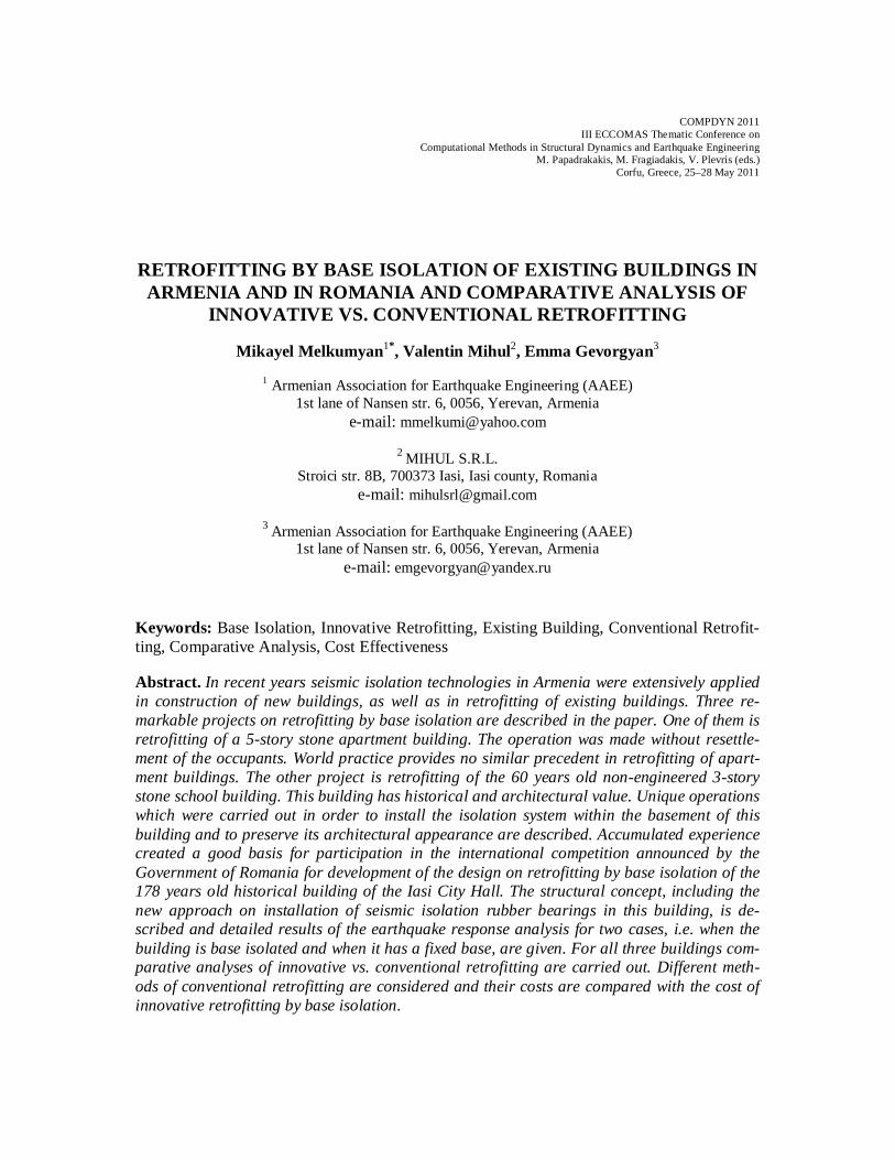
The developed structural concept aims at retrofitting an existing building by means of seismic isolators using simple working technology [8]. This is a unique pioneering seismic isolation project introduced for an existing 5-story stone building (Fig.1).
a.
b.
Figure 1: General view of the retrofitted by base isolation existing 5-story stone apartment building (a) and a
fragments of its isolation system (b)
Mikayel Melkumyan, Valentin Mihul, Emma Gevorgyan
3
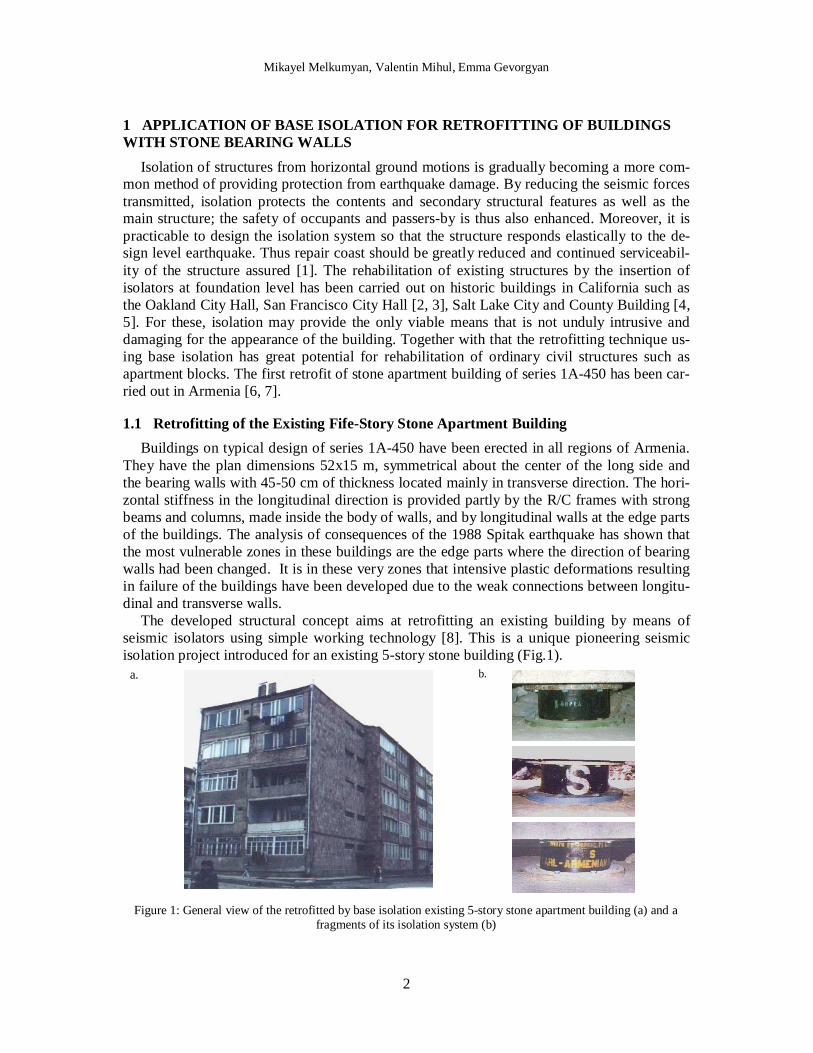
The idea is to supply this building with seismic isolation in the foundation by gradually cutting the isolators into the walls at the level of foundation upper edge by means of a two-stage system of R/C beams. Base isolation method for existing buildings with bearing walls that envisions placing of seismic isolators at the level of the foundation or the basement solves the problem as shown on Figure 2. According to the innovative technology developed by the first author of this paper (Patent of the Republic of Armenia #579), in the basement bearing walls openings with certain spacing are made to accommodate reinforcement frames of lower and upper pedestals with seismic isolators. Then reinforcement frames are placed between pedestals thus forming lower and upper continuous beams along all bearing walls of the build-ing. The parts of existing walls between seismic isolators are removed creating gaps and the building appears separated from its foundation and linked to it only by seismic isolators. It is very important that openings in walls are made so that two adjacent openings are not made simultaneously; parts of walls existing between seismic isolators should be cut off beginning from the middle of building plan.
The above described operation was made without re-settlement of the dwellers. The world practice has had no similar precedent in retrofitting of apartment buildings. The project was implemented in 1995-1996, was financed by the World Bank and co financed by UNIDO. The high damping rubber bearings (HDRB) for this retrofit project were designed with sig-nificant help and support of the UK based Malaysian Rubber Producers’ Research Associa-tion (MRPRA), particularly of Dr. K.N.G. Fuller. To implement the project 60 HDRBs were used, 28 bearings have been manufactured in MRPRA and 32 in Malaysia by Min Rubber Products Sdn. Bhd. and Sime Engineering Rubber Products Sdn. Bhd.
1.1.1 Design of Isolation System High damping rubber bearings are a simple economical means of providing isolation. They
have the low horizontal stiffness required to give a long vibration period (typically 2 s) to the structure when mounted on the bearings. Their vertical stiffness is high, thus minimizing any rocking of the structure during an earthquake. The damping needed to limit the displacement of the structure and reduce the response at the isolation frequency is incorporated into the rubber compound so that there are generally no needed auxiliary dissipation devices. The bearings can be designed to withstand safely the large horizontal displacements imposed dur-ing an earthquake. The service life of the bearings is expected to be several decades [9], and they should require no maintenance. There has been much emphasis on the suitability of base isolation for critically important structures such as hospitals and emergency centers. The pro-tection of both structure and contents, however, would be advantageous for civil structures such as apartment blocks.
The isolators are located by upper and lower recesses provided by annular steel rings bolted to outer steel plates which are connected to the reinforcement in the upper continuous and lower foundation beams; the isolators themselves are not bolted to the structure. This method of connection helps to minimize the cost of the isolators themselves and simplifies their installation on site. Because the bearing is simply located in a recess, no tapped holes for bolted connections are needed in the end-plate. The side, top and bottom rubber cover layers ensure the steel plates are protected from corrosion. In the considered existing building the bearings were not be located in an enclosed, heated basement, but would be exposed to the outside environment. The severe winter weather at the site meant that particular attention had to be paid to the low temperature crystallization resistance of the rubber compound.
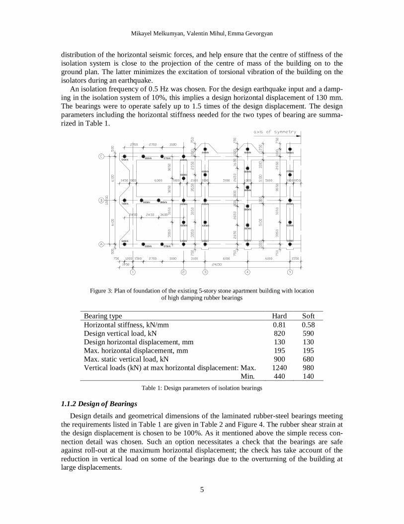
The plan of foundation is given in Figure 3, along with the location of the HDRBs and the total static load on each. The range of the vertical loads on bearings is quite high so it was de-cided to have two types of bearing, but differing only in the shear modulus of the rubber.
Mikayel Melkumyan, Valentin Mihul, Emma Gevorgyan
4
Figure 2: Stages of installation of seismic isolation system in the existing building with stone bearing walls
One type (designated Hard) would support loads in the range 740-900 kN and the other (Soft) loads in the range 500-680 kN. This strategy would lead to a somewhat more uniform
Mikayel Melkumyan, Valentin Mihul, Emma Gevorgyan
5
distribution of the horizontal seismic forces, and help ensure that the centre of stiffness of the isolation system is close to the projection of the centre of mass of the building on to the ground plan. The latter minimizes the excitation of torsional vibration of the building on the isolators during an earthquake.
An isolation frequency of 0.5 Hz was chosen. For the design earthquake input and a damp-ing in the isolation system of 10%, this implies a design horizontal displacement of 130 mm. The bearings were to operate safely up to 1.5 times of the design displacement. The design parameters including the horizontal stiffness needed for the two types of bearing are summa-rized in Table 1.
540kN
740kN
540kN
680kN
900kN
680kN 670kN
880kN
670kN640kN
600kN
900kN
600kN
640kN 840kN
630kN
890kN
630kN
840kN 500kN
900kN
880kN
880kN
900kN
500kN 840kN
630kN
890kN
630kN
840kN
Figure 3: Plan of foundation of the existing 5-story stone apartment building with location of high damping rubber bearings
Bearing type Hard Soft Horizontal stiffness, kN/mm Design vertical load, kN Design horizontal displacement, mm Max. horizontal displacement, mm Max. static vertical load, kN Vertical loads (kN) at max horizontal displacement: Max.
Min.
0.81 820 130 195 900
1240 440
0.58 590 130 195 680 980 140
Table 1: Design parameters of isolation bearings
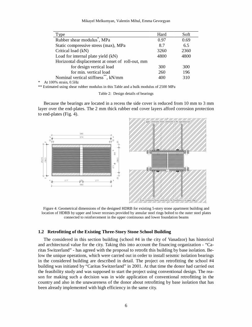
1.1.2 Design of Bearings Design details and geometrical dimensions of the laminated rubber-steel bearings meeting
the requirements listed in Table 1 are given in Table 2 and Figure 4. The rubber shear strain at the design displacement is chosen to be 100%. As it mentioned above the simple recess con-nection detail was chosen. Such an option necessitates a check that the bearings are safe against roll-out at the maximum horizontal displacement; the check has take account of the reduction in vertical load on some of the bearings due to the overturning of the building at large displacements.
Mikayel Melkumyan, Valentin Mihul, Emma Gevorgyan
6
Type Hard Soft Rubber shear modulus*, MPa 0.97 0.69 Static compressive stress (max), MPa Critical load (kN) Load for internal plate yield (kN) Horizontal displacement at onset of roll-out, mm for design vertical load for min. vertical load Nominal vertical stiffness**, kN/mm
8.7 3260 4800
300 260 400
6.5 2360 4800
300 196 310
* At 100% strain, 0.5Hz ** Estimated using shear rubber modulus in this Table and a bulk modulus of 2500 MPa
Table 2: Design details of bearings
Because the bearings are located in a recess the side cover is reduced from 10 mm to 3 mm layer over the end-plates. The 2 mm thick rubber end cover layers afford corrosion protection to end-plates (Fig. 4).
upper continuous beam connected to the superstructure
lower continuous beam connected to the foundation at its upper edge
Figure 4: Geometrical dimensions of the designed HDRB for existing 5-story stone apartment building and location of HDRB by upper and lower recesses provided by annular steel rings bolted to the outer steel plates
connected to reinforcement in the upper continuous and lower foundation beams
1.2 Retrofitting of the Existing Three-Story Stone School Building The considered in this section building (school #4 in the city of Vanadzor) has historical
and architectural value for the city. Taking this into account the financing organization - “Ca-ritas Switzerland” - has agreed with the proposal to retrofit this building by base isolation. Be-low the unique operations, which were carried out in order to install seismic isolation bearings in the considered building are described in detail. The project on retrofitting the school #4 building was initiated by “Caritas Switzerland” in 2001. At that time the donor had carried out the feasibility study and was supposed to start the project using conventional design. The rea-son for making such a decision was in wide application of conventional retrofitting in the country and also in the unawareness of the donor about retrofitting by base isolation that has been already implemented with high efficiency in the same city.
Mikayel Melkumyan, Valentin Mihul, Emma Gevorgyan
7
The school is a 3-story 60 years old building with thick bearing walls constructed using tuff stones. Actually this building is a non-engineered structure with wooden floors. The de-sign for conventional retrofitting of this school envisaged strengthening of bearing walls by reinforced concrete jackets and by construction of R/C frames in addition to the existing walls in order to decrease the distance between the existing walls. Also it was envisaged to replace the wooden floors by the R/C slabs. However, “Caritas Switzerland” being approached with a new proposal to use base isolation for retrofitting of the school instead of conventional retro-fitting had changed its initial decision. The following advantages were taken into account: high reliability, lower cost and reduced duration of construction in comparison with conven-tional retrofitting as well as preservation of the architectural view of the building.
1.2.1 Bearing Structure of the School Building
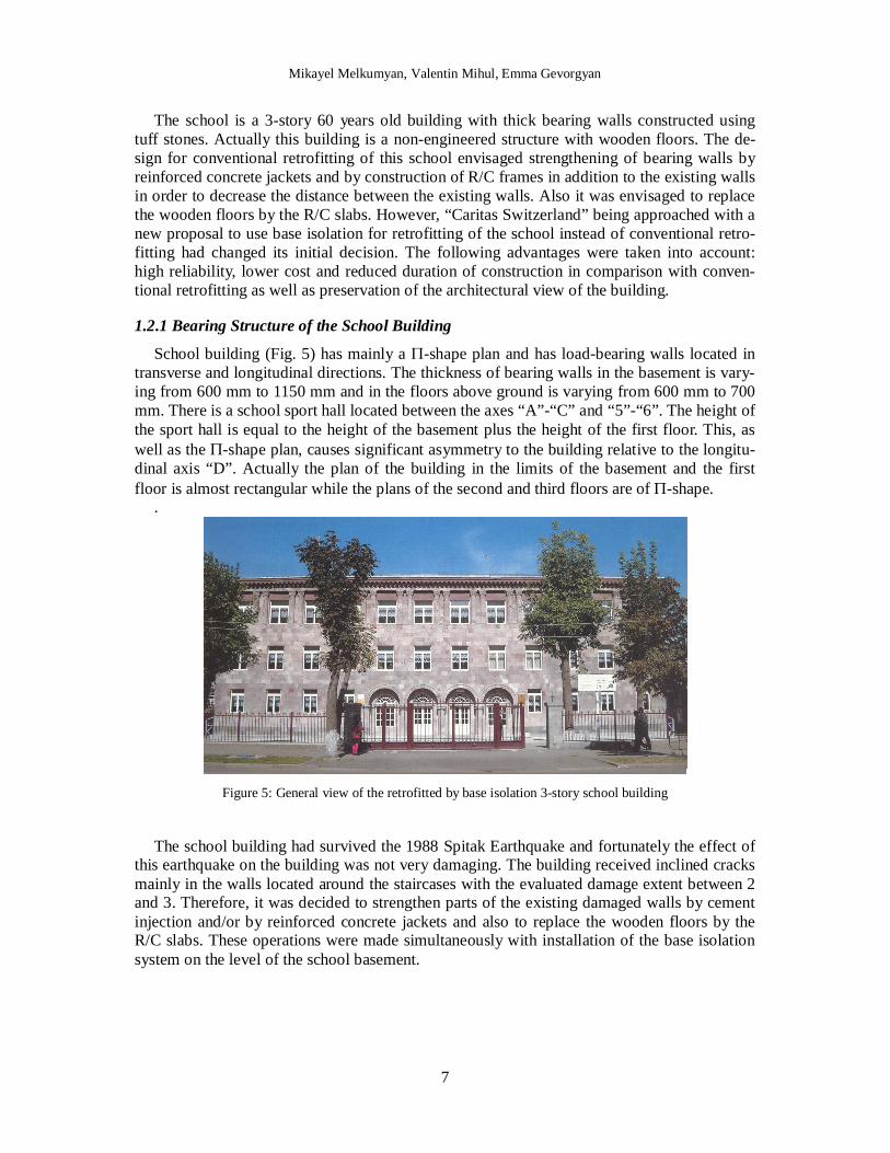
School building (Fig. 5) has mainly a -shape plan and has load-bearing walls located in transverse and longitudinal directions. The thickness of bearing walls in the basement is vary-ing from 600 mm to 1150 mm and in the floors above ground is varying from 600 mm to 700 mm. There is a school sport hall located between the axes “A”-“C” and “5”-“6”. The height of the sport hall is equal to the height of the basement plus the height of the first floor. This, as well as the -shape plan, causes significant asymmetry to the building relative to the longitu-dinal axis “D”. Actually the plan of the building in the limits of the basement and the first floor is almost rectangular while the plans of the second and third floors are of -shape.
.
Figure 5: General view of the retrofitted by base isolation 3-story school building
The school building had survived the 1988 Spitak Earthquake and fortunately the effect of
this earthquake on the building was not very damaging. The building received inclined cracks mainly in the walls located around the staircases with the evaluated damage extent between 2 and 3. Therefore, it was decided to strengthen parts of the existing damaged walls by cement injection and/or by reinforced concrete jackets and also to replace the wooden floors by the R/C slabs. These operations were made simultaneously with installation of the base isolation system on the level of the school basement.

Mikayel Melkumyan, Valentin Mihul, Emma Gevorgyan
8
1.2.2 Structural Concept of Retrofitting by Base Isolation and Technique of Installation of Rubber Bearings
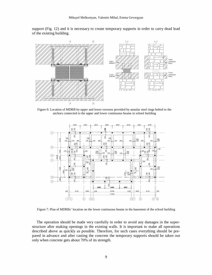
Seismic isolation interface for the school building was created in the middle part along the height of the school basement [10]. This approach has conditioned some differences in retro-fitting of the school building in comparison with the described in the Section 1.1 retrofitting of the apartment building. In the case of the school building the lower continuous beams were structurally connected to the bearing walls of the basement. This has given the possibility to strengthen the bearing walls by means of the lower continuous beams before cutting the build-ing and passing its weight through the seismic isolators to the bearing walls of the basement. Such structural solution permits to reliably carry the concentrated vertical loads by the bearing walls of the basement.
For the given project the medium damping rubber bearings from neoprene have been de-signed and tested locally. An isolation frequency again was chosen equal to 0.5 Hz. For the design level earthquake and damping in the isolation system of 8-9% the calculated horizontal displacement was equal to 140 mm. The maximal horizontal displacement was equal to 210 mm. Geometrical dimensions are the same as given in Figure 4. The other main parameters of the designed MDRBs are as follows: horizontal stiffness - 0.810.1 kN/mm; vertical stiffness - 300 kN/mm; rubber shear modulus - 0.970.15 MPa; critical vertical load - 4500 kN; verti-cal load at max horizontal displacement - 1500 kN.
The isolators in the school building were also located by the upper and lower recesses, however, the annular steel rings in this case were bolted directly to the anchors. The outer steel plates were also modified and instead of 20 mm thick plates the 6 mm plates were envis-aged (Fig. 6). The given modifications in the design of the isolators’ sockets have brought to significant reduction of steel consumption. Figure 6 also shows the cross-sections of the base-ment bearing wall in the place where isolator is installed between the lower and upper pedes-tals and where there is no isolator but the lower and upper continuous beams are seen from both sides of the bearing wall. All together 41 MDRBs had been manufactured by the Yere-van Factory of Rubber Technical Articles (YFRTA) for retrofitting of school building. The plan of location of seismic isolators on the lower continuous beams is shown on Figure 7.
For the considered building, which has historical and architectural value the technique of installation of seismic isolators has especially important meaning. First of all an infringement of the external view of the building should not take place under any circumstances. Secondly, no one stone of the façade should fall down during making openings in the bearing walls.
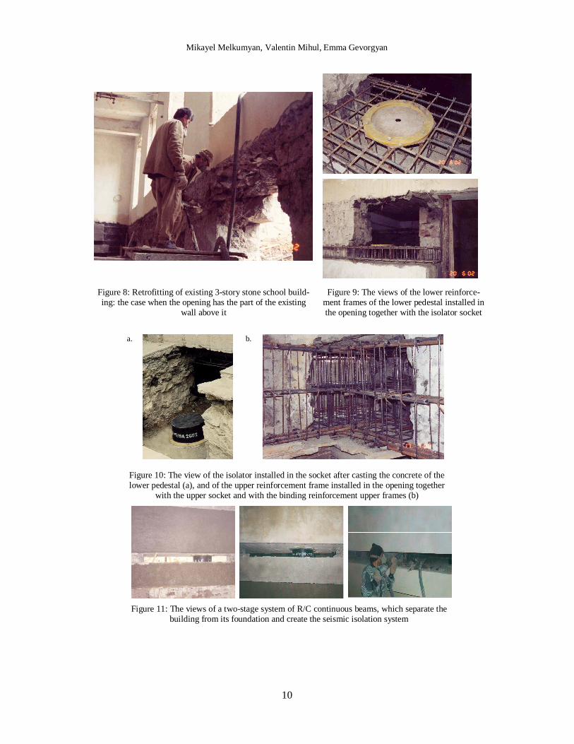
There are three different cases of making openings in the existing walls of the basement, which were mainly used at the retrofitting of the building [11]. The relatively simple case is the one, when the opening has the part of existing wall above it (Fig. 8). In this case there is no need to put any additional supports, as the strength of the wall is sufficient in order to avoid falling. When the opening is made, the lower reinforcement frame of the lower pedestal with the isolator socket can be placed and after that binding reinforcement lower frames are passed along both sides of bearing wall through the frame of the lower pedestal (Fig. 9).
At the next step the concrete of the lower pedestal is casted, the isolator is installed (Fig. 10) and above it the upper socket and the reinforcement frame of the upper pedestal are placed. Then the binding reinforcement upper frames are passed through the reinforcement frame of the upper pedestal along both sides of existing bearing wall (Fig.10). After casting the concrete of the upper pedestal all lower and upper pedestals should be connected to each other forming a two-stage system of R/C continuous beams (Fig. 11).
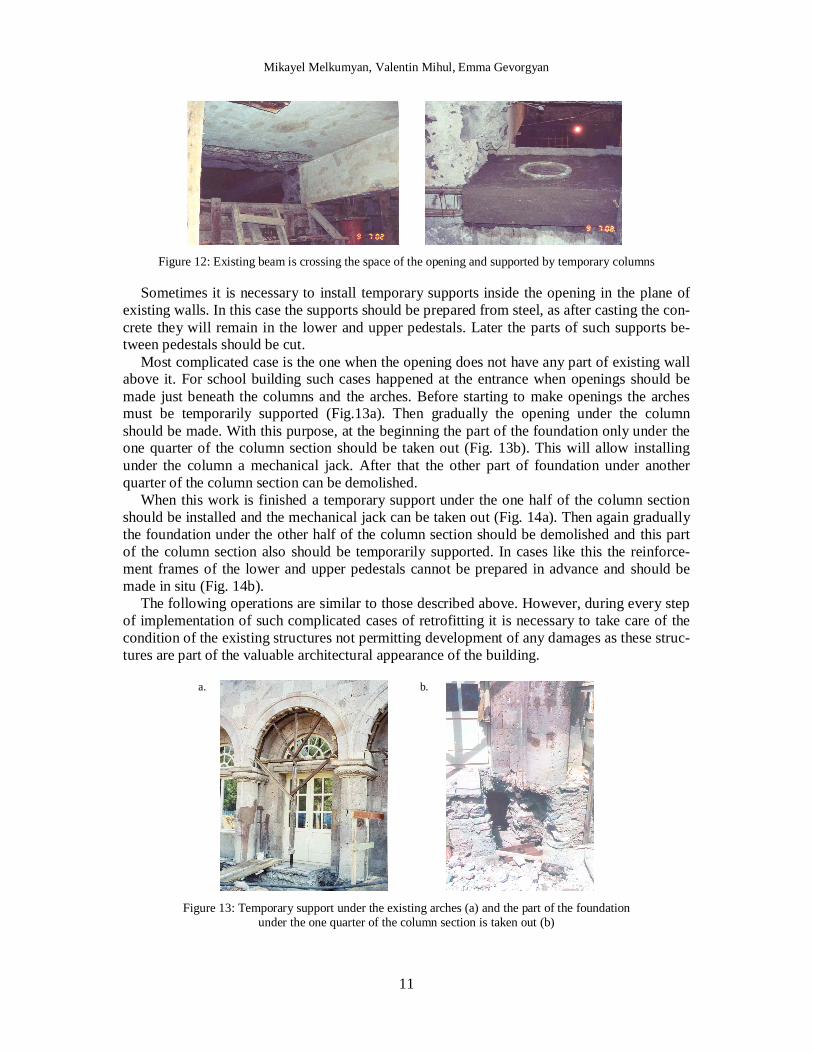
More complicated case of making openings is when any of existing beams or girders is crossing the space of the opening. In this case one of the ends of the existing beam loses its
Mikayel Melkumyan, Valentin Mihul, Emma Gevorgyan
9
support (Fig. 12) and it is necessary to create temporary supports in order to carry dead load of the existing building.
upper continuous beam connected to the superstructure
lower continuous beam connected to the bearing walls of the basement
1
1
2
2
2 - 21 - 1
Lowerpedestal
Upperpedestal
Lowercontinuousbeam
Uppercontinuousbeam
Figure 6: Location of MDRB by upper and lower recesses provided by annular steel rings bolted to the anchors connected to the upper and lower continuous beams in school building
1 2 3 4 5 6 7 8 9 10
400 6150 2800 1100 40061502800110016300
37200
5000 500063005000 50006300
A
B
1800
7200
C
D
E
F
2000
3500
6150
2065
0
4500 4450 4650 4600 450044504650460027
00
700
150
150
1150150
150
150
150
300700
150150 150150 150150 150150 150150300 300 300
150
150
700
150
150
300
150
150
150
150
300
150
150 15
070
015
0
700
150
150
150
150
450
150
450
150
150 150700
150 150 150 150300
4600
700
300 300
700
700
700
700
700
700
700
700
700
700
700700 700 700
700 700
700
700
700 700
700
150150 150 150 150150
150150
Figure 7: Plan of MDRBs’ location on the lower continuous beams in the basement of the school building
The operation should be made very carefully in order to avoid any damages in the super-
structure after making openings in the existing walls. It is important to make all operations described above as quickly as possible. Therefore, for such cases everything should be pre-pared in advance and after casting the concrete the temporary supports should be taken out only when concrete gets about 70% of its strength.
Mikayel Melkumyan, Valentin Mihul, Emma Gevorgyan
10
Figure 8: Retrofitting of existing 3-story stone school build-ing: the case when the opening has the part of the existing
wall above it
Figure 9: The views of the lower reinforce-ment frames of the lower pedestal installed in the opening together with the isolator socket
a.
b.
Figure 10: The view of the isolator installed in the socket after casting the concrete of the lower pedestal (a), and of the upper reinforcement frame installed in the opening together
with the upper socket and with the binding reinforcement upper frames (b)
Figure 11: The views of a two-stage system of R/C continuous beams, which separate the building from its foundation and create the seismic isolation system
Mikayel Melkumyan, Valentin Mihul, Emma Gevorgyan
11
Figure 12: Existing beam is crossing the space of the opening and supported by temporary columns
Sometimes it is necessary to install temporary supports inside the opening in the plane of existing walls. In this case the supports should be prepared from steel, as after casting the con-crete they will remain in the lower and upper pedestals. Later the parts of such supports be-tween pedestals should be cut.
Most complicated case is the one when the opening does not have any part of existing wall above it. For school building such cases happened at the entrance when openings should be made just beneath the columns and the arches. Before starting to make openings the arches must be temporarily supported (Fig.13a). Then gradually the opening under the column should be made. With this purpose, at the beginning the part of the foundation only under the one quarter of the column section should be taken out (Fig. 13b). This will allow installing under the column a mechanical jack. After that the other part of foundation under another quarter of the column section can be demolished.
When this work is finished a temporary support under the one half of the column section should be installed and the mechanical jack can be taken out (Fig. 14a). Then again gradually the foundation under the other half of the column section should be demolished and this part of the column section also should be temporarily supported. In cases like this the reinforce-ment frames of the lower and upper pedestals cannot be prepared in advance and should be made in situ (Fig. 14b).
The following operations are similar to those described above. However, during every step of implementation of such complicated cases of retrofitting it is necessary to take care of the condition of the existing structures not permitting development of any damages as these struc-tures are part of the valuable architectural appearance of the building.
a.
b.
Figure 13: Temporary support under the existing arches (a) and the part of the foundation under the one quarter of the column section is taken out (b)

Mikayel Melkumyan, Valentin Mihul, Emma Gevorgyan
12
a.
b.
Figure 14: Temporary support under the one half of the existing column section (a), and existing column and the wall behind it are supported temporarily and the reinforcement
frame of the upper pedestal is installed (b)
1.3 Retrofitting Design of the Existing Cultural Heritage Iasi City Hall Building (Iasi County, Romania) by Means of Base Isolation
Experience accumulated in Armenia in retrofitting of existing buildings including those of historical and architectural value created a good basis for participation in the international competition announced by the Government of Romania for development of the design on ret-rofitting by base isolation of the 178 years old historical building of the Iasi City Hall (Fig. 15). Design was developed in cooperation with Romanian company MIHUL S.R.L. It was approved by the Technical Committee for Seismic Rick Reduction (TCSRR, a body especially created by the Government of Romania) on June 1, 2009.
Figure 15: Views of the Iasi City Hall building
The structural system consists of un-reinforced masonry walls with primarily wood hori-zontal diaphragms. The thicknesses of the interior and exterior walls vary between 40 to 60 cm and up to 100 cm respectively. Stone foundations have been provided under the masonry bearing walls. The building suffered repairable damage after the 1977 Vrancea earthquake. Thus, the bearing walls were repaired by grout injection, reinforced concrete slabs replaced damaged floors, and the tall chimneys were anchored in place using steel ties. The Iasi City Hall is located in the seismic zone C, and based on Romanian Building Code P100-92, the expected peak ground acceleration for that zone is 0.2 g. The soil in the vicinity of the build-ing is classified as stiff clay sensitive to moisture; the ground water table is approximately 6 m below surface [12]. However, the TCSRR has requested to accept the peak ground accel-eration (PGA) for retrofitting design of the Iasi City Hall building equal to 0.28 g. TCSRR had justified its request mentioning that either for the 100 years mean recurrence interval
Mikayel Melkumyan, Valentin Mihul, Emma Gevorgyan
13
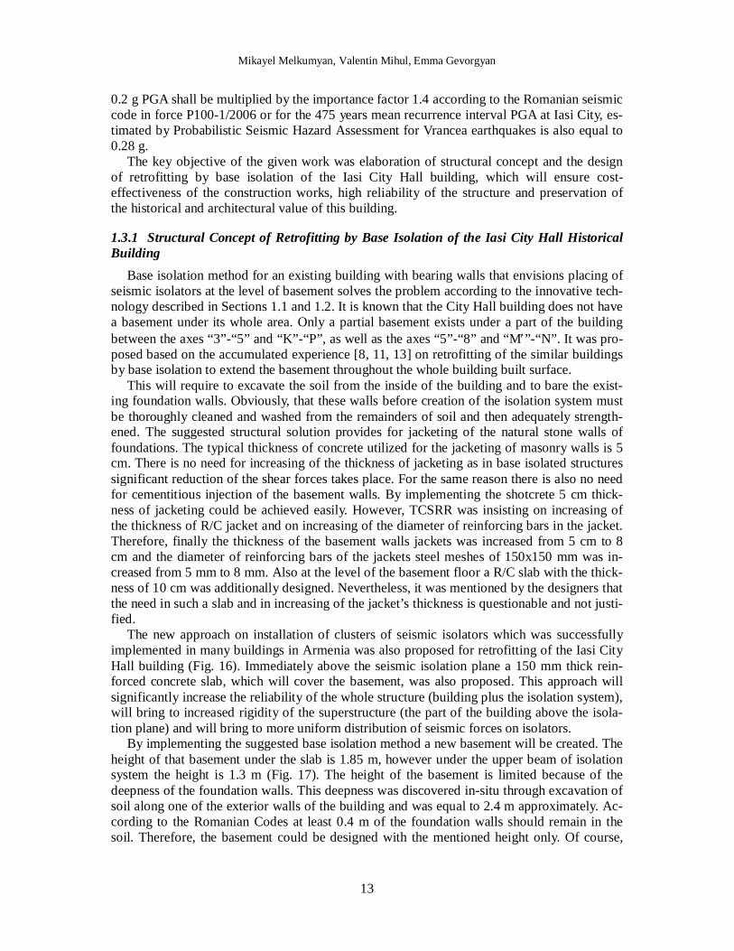
0.2 g PGA shall be multiplied by the importance factor 1.4 according to the Romanian seismic code in force P100-1/2006 or for the 475 years mean recurrence interval PGA at Iasi City, es-timated by Probabilistic Seismic Hazard Assessment for Vrancea earthquakes is also equal to 0.28 g.
The key objective of the given work was elaboration of structural concept and the design of retrofitting by base isolation of the Iasi City Hall building, which will ensure cost-effectiveness of the construction works, high reliability of the structure and preservation of the historical and architectural value of this building.
1.3.1 Structural Concept of Retrofitting by Base Isolation of the Iasi City Hall Historical Building
Base isolation method for an existing building with bearing walls that envisions placing of seismic isolators at the level of basement solves the problem according to the innovative tech-nology described in Sections 1.1 and 1.2. It is known that the City Hall building does not have a basement under its whole area. Only a partial basement exists under a part of the building between the axes “3”-“5” and “K”-“P”, as well as the axes “5”-“8” and “M”-“N”. It was pro-posed based on the accumulated experience [8, 11, 13] on retrofitting of the similar buildings by base isolation to extend the basement throughout the whole building built surface.
This will require to excavate the soil from the inside of the building and to bare the exist-ing foundation walls. Obviously, that these walls before creation of the isolation system must be thoroughly cleaned and washed from the remainders of soil and then adequately strength-ened. The suggested structural solution provides for jacketing of the natural stone walls of foundations. The typical thickness of concrete utilized for the jacketing of masonry walls is 5 cm. There is no need for increasing of the thickness of jacketing as in base isolated structures significant reduction of the shear forces takes place. For the same reason there is also no need for cementitious injection of the basement walls. By implementing the shotcrete 5 cm thick-ness of jacketing could be achieved easily. However, TCSRR was insisting on increasing of the thickness of R/C jacket and on increasing of the diameter of reinforcing bars in the jacket. Therefore, finally the thickness of the basement walls jackets was increased from 5 cm to 8 cm and the diameter of reinforcing bars of the jackets steel meshes of 150x150 mm was in-creased from 5 mm to 8 mm. Also at the level of the basement floor a R/C slab with the thick-ness of 10 cm was additionally designed. Nevertheless, it was mentioned by the designers that the need in such a slab and in increasing of the jacket’s thickness is questionable and not justi-fied.
The new approach on installation of clusters of seismic isolators which was successfully implemented in many buildings in Armenia was also proposed for retrofitting of the Iasi City Hall building (Fig. 16). Immediately above the seismic isolation plane a 150 mm thick rein-forced concrete slab, which will cover the basement, was also proposed. This approach will significantly increase the reliability of the whole structure (building plus the isolation system), will bring to increased rigidity of the superstructure (the part of the building above the isola-tion plane) and will bring to more uniform distribution of seismic forces on isolators.
By implementing the suggested base isolation method a new basement will be created. The height of that basement under the slab is 1.85 m, however under the upper beam of isolation system the height is 1.3 m (Fig. 17). The height of the basement is limited because of the deepness of the foundation walls. This deepness was discovered in-situ through excavation of soil along one of the exterior walls of the building and was equal to 2.4 m approximately. Ac-cording to the Romanian Codes at least 0.4 m of the foundation walls should remain in the soil. Therefore, the basement could be designed with the mentioned height only. Of course,
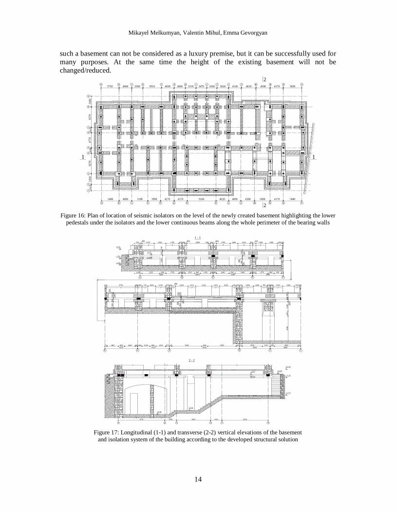
Mikayel Melkumyan, Valentin Mihul, Emma Gevorgyan
14
such a basement can not be considered as a luxury premise, but it can be successfully used for many purposes. At the same time the height of the existing basement will not be changed/reduced.
5750 4060 3500 5910 403019
7033
5065
7016
9047
7016
1065
703680 3310
5480 4060 5180
3470 3260 3630
3990 4270 4170 9160 4020 5000 4170 58404000 4300
4170 58304130 4610 4560L''
L'
M'G' J'
4
8
7
1
2
3
5
6
9
A' C D I JB F G L N O P
CA L NKB E MG H OE' P
3300
1 1
2
2
Figure 16: Plan of location of seismic isolators on the level of the newly created basement highlighting the lower pedestals under the isolators and the lower continuous beams along the whole perimeter of the bearing walls
E'ECBA5480 4060 5180 3990
H K9160
GE' L L'41704270 4020 4000
750250
400400 360440
335415
125
225 300 600 475325 435355 400400 150
1000 420400 340460 320430 235
275 300 600 475 325 435355 1015 585
700
200
300
3240
1230
660
700
200
300
800
50
-1.25
-0.05
-2.05
1015 1025
1705 1610 650
150
550
1300
2325 800 1705 1195 800 1305 1640 800 1960 1570 800 950
3750 1335 1650 2100 1650 785 700
150
550
200
300
800
150
100
200
300
800
1495 800 1400 1030 800 1265 3905 800 3695 2650 3065 350
15501575 2800 10001790 15001300
1000755460
505 10001480 15001250
1 - 1250
250
-0.75
-0.95
8
-1.25
-0.05
-0.75
-0.95
-0.65
-3.71
7543
6570 1690 4810 6530
-5.81
-6.38
2 - 2
6
1610
Figure 17: Longitudinal (1-1) and transverse (2-2) vertical elevations of the basement and isolation system of the building according to the developed structural solution

Mikayel Melkumyan, Valentin Mihul, Emma Gevorgyan
15
Regarding the bearing walls above the isolation interface it is suggested to execute local strengthening of walls where local cracks exist by cement injection in the cracks and by fixing here of 6 mm steel clamps and plastering those parts. This is just a constructive measure, which is actually not required by carried out calculations. Despite this TCSRR has requested to change the mentioned clamps by the steel meshes of 100x100 mm with the reinforcing bars of diameter 8 mm.
1.3.2 Seismic Isolation Laminated Rubber Steel Bearings (SILRSB) to be Applied for Retrofitting of the Iasi City Hall and Some Results of its Earthquake Response Analysis
In order to develop the retrofitting design the Iasi City Hall building was analyzed under the seismic impacts with PGA equal to 0.28g following the request of TCSRR. This commit-tee has also mentioned that according to the Code P100-1/2006 the demand spectral dis-placement at the period of vibrations of base isolated building equal to 2.0 sec and the damping ratio of 5% for Iasi is 27 cm. Therefore, it was suggested by designers to accept the value of the actual damping ratio for seismic isolators equal to 15%. In this case according to the Annex A of P100-1/2006 the mentioned displacement demand shall be recomputed and reduced by a factor of 0.707 (27x0.707=19.09 cm). Period of vibrations of the base isolated Iasi City Hall building, as it is given in [15], is the same in longitudinal (X) and in transverse (Y) directions and is equal to 2.13 sec. This means that the calculated displacement demand will actually be equal to 2:2.13x19.09=17.92 cm. TCSRR has also mentioned that “Good practice and the international codes request a total displacement for design increased by 50% with respect to displacement demand”. Satisfying this requirement the final value of a total displacement D=17.92x1.5=26.88 cm was accepted for retrofitting design of the Iasi City Hall building.
However, the statement given by TCSRR about a total displacement seems weak and not justified. In Science and Engineering such statements are not acceptable as they are not clear and are made without any references. Also when it is stated as “Good practice …” shall some one understand that there is a “Better practice…” or “Best practice…” and what has to be done in these cases? Most probably the absence of the extensive experience on base isolation in Romania is forcing the members of TCSRR to require an over designed isolation system, which will bring to artificial increase of the cost of retrofitting of the Iasi City Hall building. Is there a need for that? Those countries, which are currently extensively using seismic isola-tion technologies for retrofitting or for new construction like Japan [16], Russia [17], China [18], Italy [19], Armenia [13], and others are constantly reporting on reliability and cost effec-tiveness of these technologies.
If it is so then why seismic isolation should be expensive in Romania? There is a risk that in case of artificial increase of retrofitting cost the Iasi City Hall, being over designed, will become the first and the last building retrofitted by base isolation following the sad experi-ence of USA where because of similar extremely high conservatism seismic isolation is actu-ally dying. But TCSRR was arbitrarily requesting to significantly increase the values of PGA and of design displacement of isolation system. This was forcedly done in the design with the understanding that it will raise the cost of retrofitting works unnecessarily.
Based on the above for creation of seismic isolation system under the Iasi City Hall build-ing the SILRSBs made from neoprene were accepted similar to those used for retrofitting of the apartment and school buildings with the damping factor equal to 15% [14]. Earthquake response analysis of the building was carried out by SAP2000 non-linear program. The design model was developed using different types of finite elements for walls, floor slabs and seis-mic isolators.
Mikayel Melkumyan, Valentin Mihul, Emma Gevorgyan
16
The non-linearity was considered only for seismic isolators because for cases like Iasi City Hall building there is no need to apply non-linearity to superstructure. For the linear model the isolators are given the effective stiffness equal to 0.81 kN/mm. For non-linear model the isolators have initial stiffness equal to 3 kN/mm and post yield stiffness equal to 0.81 kN/mm.
For the analysis TCSRR has requested to select only those acceleration time histories which “… characterized by a corner period of response spectra Tc close to the value of 0.7 sec. The design accelerograms might be also compatable with local soil condition in Iasi, as those conditions have been experienced during the Vrancea 1986 and 1990 earthquakes”. Finally 9 accelerograms were selected and scaled to acceleration 0.28g: 4.03.1977 Vrancea Earthquake, EW direction at Buc-INCERC station (Tc = 0.78); 30.05.1990 Vrancea Earthquake, EW di-rection at Buc-Magurele station (Tc = 0.64); 30.08.1986 Vrancea Earthquake, NS direction at Iasi station (Tc = 0.44); 30.08.1986 Vrancea Earthquake, EW direction at Iasi station (Tc = 0.36); 31.05.1990 Vrancea Earthquake, EW direction at Iasi station (Tc = 0.40); 30.08.1986 Vrancea Earthquake, NS direction at Istrita station (Tc = 0.62); 31.05.1990 Vrancea Earth-quake, EW direction at Istrita station (Tc = 0.64); 30.08.1986 Vrancea Earthquake, NS direc-tion at Muntele Rosu station (Tc = 0.70); 30.05.1990 Vrancea Earthquake, EW direction at Muntele Rosu station (Tc = 0.72).
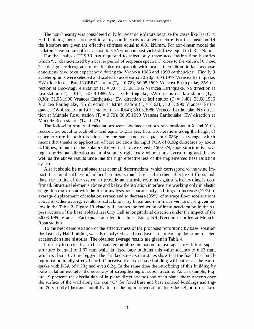
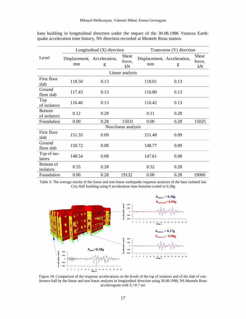
The following results of calculations were obtained: periods of vibrations in X and Y di-rections are equal to each other and equal to 2.13 sec; floor accelerations along the height of superstructure in both directions are the same and are equal to 0.085g in average, which means that thanks to application of base isolation the input PGA of 0.28g decreases by about 3.3 times; in none of the isolators the vertical force exceeds 1500 kN; superstructure is mov-ing in horizontal direction as an absolutely rigid body without any overturning and this as well as the above results underline the high effectiveness of the implemented base isolation system. Also it should be mentioned that at small deformations, which correspond to the wind im-pact, the initial stiffness of rubber bearings is much higher than their effective stiffness and, thus, the ability of the system to provide an intrinsic restraint against wind loading is con-firmed. Structural elements above and below the isolation interface are working only in elastic stage. In comparison with the linear analysis non-linear analysis brings to increase (27%) of average displacement of isolation system and to decrease (35%) of average floor accelerations above it. Other average results of calculations by linear and non-linear versions are given be-low in the Table 3. Figure 18 visually illustrates the reduction of input acceleration in the su-perstructure of the base isolated Iasi City Hall in longitudinal direction under the impact of the 30.08.1986 Vrancea Earthquake acceleration time history, NS direction recorded at Muntele Rosu station.
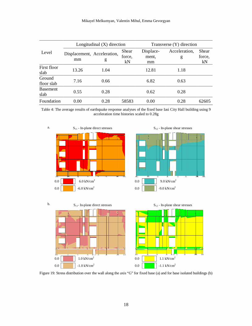
To the best demonstration of the effectiveness of the proposed retrofitting by base isolation the Iasi City Hall building was also analyzed as a fixed base structure using the same selected acceleration time histories. The obtained average results are given in Table 4.
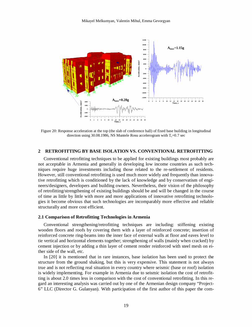
It is easy to notice that in base isolated building the maximum average story drift of super-structure is equal to 1.67 mm while in fixed base building this value reaches to 6.23 mm, which is about 3.7 time bigger. The checked stress-strain states show that the fixed base build-ing must be totally strengthened. Otherwise the fixed base building will not resist the earth-quake with PGA of 0.28g and even 0.2g. In the same time the retrofitting of this building by base isolation excludes the necessity of strengthening of superstructure. As an example, Fig-ure 19 presents the distribution of in-plane direct stresses and of in-plane shear stresses over the surface of the wall along the axis “G” for fixed base and base isolated buildings and Fig-ure 20 visually illustrates amplification of the input acceleration along the height of the fixed
Mikayel Melkumyan, Valentin Mihul, Emma Gevorgyan
17
base building in longitudinal direction under the impact of the 30.08.1986 Vrancea Earth-quake acceleration time history, NS direction recorded at Muntele Rosu station.
Longitudinal (X) direction Transverse (Y) direction
Level Displacement, mm
Acceleration, g
Shear force,
kN
Displacement, mm
Acceleration, g
Shear force,
kN Linear analysis
First floor slab 118.50 0.13 118.01 0.13
Ground floor slab 117.43 0.13 116.80 0.13
Top of isolators 116.40 0.13 116.42 0.13
Bottom of isolators 0.12 0.28 0.11 0.28
Foundation 0.00 0.28 15031 0.00 0.28 15025 Non-linear analysis
First floor slab 151.35 0.09 151.48 0.09
Ground floor slab 150.72 0.08 148.77 0.09
Top of iso-lators 148.54 0.08 147.61 0.08
Bottom of isolators 0.55 0.28 0.52 0.28
Foundation 0.00 0.28 19132 0.00 0.28 19000 Table 3: The average results of the linear and non-linear earthquake response analyses of the base isolated Iasi
City Hall building using 9 acceleration time histories scaled to 0.28g
Figure 18. Comparison of the response accelerations on the levels of the top of isolators and of the slab of con-ference hall by the linear and non linear analyses in longitudinal direction using 30.08.1986, NS Muntele Rosu
accelerogram with Tc=0.7 sec
Amax.l. = 0.18g Amax.n.l.= 0.09g
Amax=0.28g
Amax.l. = 0.17g Amax.n.l.= 0.08g
0 2 4 6 8 10 12 14 16 18 20 22 24 26 28 30Time, s
-2800
-1400
0
1400
2800
Acc
eler
atio
n, m
m/s2
0 2 4 6 8 10 12 14 16 18 20 22 24 26 28 30Time, s
-2800
-1400
0
1400
2800
Acc
eler
atio
n, m
m/s2
0 2 4 6 8 10 12 14 16 18 20 22 24 26 28 30Time, s
-2800
-1400
0
1400
2800
Acc
eler
atio
n, m
m/s2
Mikayel Melkumyan, Valentin Mihul, Emma Gevorgyan
18
Longitudinal (X) direction Transverse (Y) direction
Level Displacement, mm
Acceleration, g
Shear force,
kN
Displace-ment, mm
Acceleration, g
Shear force,
kN First floor slab 13.26 1.04 12.81 1.18
Ground floor slab 7.16 0.66 6.82 0.63
Basement slab 0.55 0.28 0.62 0.28
Foundation 0.00 0.28 58583 0.00 0.28 62605
Table 4: The average results of earthquake response analyses of the fixed base Iasi City Hall building using 9 acceleration time histories scaled to 0.28g
a. S11 - In-plane direct stresses S12 - In-plane shear stresses
0.0 6.0 kN/cm2 0.0 9.0 kN/cm2
0.0 -6.0 kN/cm2 0.0 -9.0 kN/cm2
b. S11- In-plane direct stresses S12 - In-plane shear stresses
0.0 1.0 kN/cm2 0.0 1.1 kN/cm2
0.0 -1.0 kN/cm2 0.0 -1.1 kN/cm2 Figure 19: Stress distribution over the wall along the axis “G” for fixed base (a) and for base isolated buildings (b)
Mikayel Melkumyan, Valentin Mihul, Emma Gevorgyan
19
Figure 20: Response acceleration at the top (the slab of conference hall) of fixed base building in longitudinal direction using 30.08.1986, NS Muntele Rosu accelerogram with Tc=0.7 sec
2 RETROFITTING BY BASE ISOLATION VS. CONVENTIONAL RETROFITTING Conventional retrofitting techniques to be applied for existing buildings most probably are
not acceptable in Armenia and generally in developing low income countries as such tech-niques require huge investments including those related to the re-settlement of residents. However, still conventional retrofitting is used much more widely and frequently than innova-tive retrofitting which is conditioned by the lack of knowledge and by conservatism of engi-neers/designers, developers and building owners. Nevertheless, their vision of the philosophy of retrofitting/strengthening of existing buildings should be and will be changed in the course of time as little by little with more and more applications of innovative retrofitting technolo-gies it become obvious that such technologies are incomparably more effective and reliable structurally and more cost efficient.
2.1 Comparison of Retrofitting Technologies in Armenia Conventional strengthening/retrofitting techniques are including: stiffening existing
wooden floors and roofs by covering them with a layer of reinforced concrete; insertion of reinforced concrete ring-beams into the inner face of external walls at floor and eaves level to tie vertical and horizontal elements together; strengthening of walls (mainly when cracked) by cement injection or by adding a thin layer of cement render reinforced with steel mesh on ei-ther side of the wall, etc.
In [20] it is mentioned that in rare instances, base isolation has been used to protect the structure from the ground shaking, but this is very expensive. This statement is not always true and is not reflecting real situation in every country where seismic (base or roof) isolation is widely implementing. For example in Armenia due to seismic isolation the cost of retrofit-ting is about 2.0 times less in comparison with the cost of conventional retrofitting. In this re-gard an interesting analysis was carried out by one of the Armenian design company “Project-6” LLC (Director G. Gulanyan). With participation of the first author of this paper the com-
0 2 4 6 8 10 12 14 16 18 20 22 24 26 28 30Time, s
-12000
-10000
-8000
-6000
-4000
-2000
0
2000
4000
6000
8000
10000
12000
Acc
eler
atio
n, m
m/s2
Amax=1.15g
Amax=0.28g
0 2 4 6 8 10 12 14 16 18 20 22 24 26 28 30Time, s
-2800
-1400
0
1400
2800
Acc
eler
atio
n, m
m/s2

Mikayel Melkumyan, Valentin Mihul, Emma Gevorgyan
20
pany has analyzed and compared the cost of strengthening of existing stone apartment build-ings of series 1A-450 by different methods (Tab. 5). It was assumed that the cost of the most expensive method of traditional strengthening comprises 100%.
Method of strengthening Cost in % Needed action
Traditional method with application of reinforced concrete jackets, frames and floor slabs. This method is applicable for buildings with damage extent from 2 to 3*
100
Evacuation of tenants, move out furniture
Traditional method with application of only rein-forced concrete frames. This method is applicable for buildings with damage extent from 1 to 2
43 Evacuation of tenants
Innovative method with application of base isola-tion and local strengthening of walls only by rein-forced concrete jackets. This method is applicable for buildings with damage extent from 2 to 3*
37
Without evacuation of tenants, partial move of furniture
Innovative method with application of base isola-tion and total strengthening of walls by cement injection. This method is applicable for buildings with damage extent from 2 to 3
31
Without evacuation of tenants, partial move of furniture
The same as previous but with local strengthening of wall by cement injection for buildings with damage extent from 1 to 2
27 Without evacuation of tenants, partial move of furniture
The same as previous without touching the super-structure for buildings with damage extent from 0 to 1
21 Without evacuation of tenants
* This method can also be applied for buildings with damage extent 4, however, with due regard of economic and social factors
Table 5: Comparison of the cost of strengthening of existing stone apartment buildings of series 1A-450 by different methods
From Table 5 it follows that in Armenia the cost of innovative method of strengthen-ing/retrofitting of stone apartment buildings with application of base isolation is 2.5 times less in average in comparison with the cost of traditional methods of retrofitting. And this is of course with consideration of the cost of seismic isolation rubber bearings but without consid-eration of the cost of evacuation of tenants. It is easy to understand that evacuation of tenants requires huge additional investments in order to provide evacuated tenants with temporary shelters, water, sewer, electricity and relevant infrastructure. Consideration of these additional investments makes in absolutely clear and obvious that at least in those earthquake prone countries where progressive thinking of designers/engineers, developers, building owners and decision-makers, as well as progressive codes are exist and also where it is possible manufac-turing or importing low-cost seismic isolators the preference should be given to the innovative methods of retrofitting with application of base isolation. In the result of its analysis “Project-6” had concluded that the most cost effective technique for strengthening of existing buildings is base isolation in combination with cement injection or with polymer-cement slurry injec-tion for total or local strengthening of the damaged bearing walls.
Above several remarkable projects on retrofitting by base isolation are described. One of them is retrofitting of the existing stone apartment building of series 1A-450 in the city of Vanadzor. This project is an actual example of cost effectiveness of retrofitting by base isola-

Mikayel Melkumyan, Valentin Mihul, Emma Gevorgyan
21
tion vs. conventional retrofitting. The cost of retrofitting of this building defined in the result of competitive bidding is equal to 165.600 USD including the cost of rubber bearings. Other two similar buildings in the same city were retrofitted conventionally. One was retrofitted with application of reinforced concrete jackets and frames and it cost is equal to 340.000 USD. The other one was retrofitted by insertion only of reinforced concrete horizontal ring-beams and vertical columns into the external and internal bearing walls and it cost is equal to 294.200 USD. These actual examples prove ones again that substantial saving (about 2.0 times) could be achieved thanks to application of base isolation. Also this innovative technol-ogy allows avoiding infringement of the external and internal views of the buildings which is extremely important especially at seismic protection of historic buildings and structures of cultural heritage like, for example, the above described building of Iasi City Hall.
2.2 Comparison of Retrofitting Technologies in Romania Special analysis was carried out by the second author of this paper in order to reveal cost
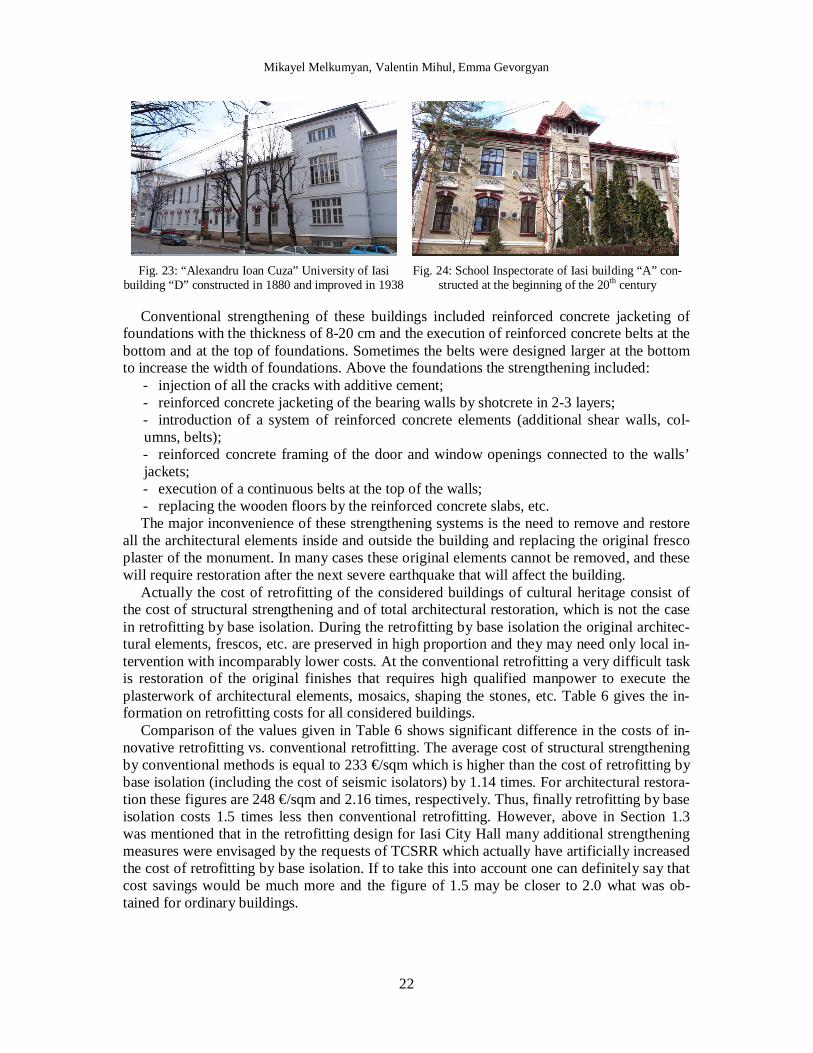
effectiveness of retrofitting by base isolation of the buildings that represent an architectural monument. Four buildings were considered which were strengthened conventionally (Fig. 21, 22, 23 and 24) and the results were compared with those obtained in retrofitting design of Iasi City Hall by application of base isolation.
Structural systems of these buildings as well as of the Iasi City Hall building are similar. They have bearing walls made of brick on the continuous stone masonry foundation. Their floors are made of wooden beams but above the basements (if there are) the floors are made of small brick arches. The shaped limestone of foundations is walled up with dirty sand and lime mortar. The compressive strength of brick corresponds to the grade of 25-50 and of mor-tar – to the grade of 4-10.
In the considered buildings there were inclined cracks observed along the height of the bearing walls with the opening of 1-3 mm. Most of them occurred around the windows and doors as a possible result of the earthquake impact. Also cracks are usually increase in their number, length and openings by the uneven settlements of the ground under the foundation because of wetting or exceeding its local bearing capacity.
Fig. 21: View of “Georghe Pirvan “ Museum, Bârlad
constructed in 1880 Fig. 22: View of Palace of “Alexandru Ioan Cuza” Uni-versity of Iasi which was constructed in two stages: first
in 1894 and then in 1928-1934
Mikayel Melkumyan, Valentin Mihul, Emma Gevorgyan
22
Fig. 23: “Alexandru Ioan Cuza” University of Iasi
building “D” constructed in 1880 and improved in 1938 Fig. 24: School Inspectorate of Iasi building “A” con-
structed at the beginning of the 20th century
Conventional strengthening of these buildings included reinforced concrete jacketing of foundations with the thickness of 8-20 cm and the execution of reinforced concrete belts at the bottom and at the top of foundations. Sometimes the belts were designed larger at the bottom to increase the width of foundations. Above the foundations the strengthening included:
- injection of all the cracks with additive cement; - reinforced concrete jacketing of the bearing walls by shotcrete in 2-3 layers; - introduction of a system of reinforced concrete elements (additional shear walls, col-umns, belts); - reinforced concrete framing of the door and window openings connected to the walls’ jackets; - execution of a continuous belts at the top of the walls; - replacing the wooden floors by the reinforced concrete slabs, etc. The major inconvenience of these strengthening systems is the need to remove and restore
all the architectural elements inside and outside the building and replacing the original fresco plaster of the monument. In many cases these original elements cannot be removed, and these will require restoration after the next severe earthquake that will affect the building.
Actually the cost of retrofitting of the considered buildings of cultural heritage consist of the cost of structural strengthening and of total architectural restoration, which is not the case in retrofitting by base isolation. During the retrofitting by base isolation the original architec-tural elements, frescos, etc. are preserved in high proportion and they may need only local in-tervention with incomparably lower costs. At the conventional retrofitting a very difficult task is restoration of the original finishes that requires high qualified manpower to execute the plasterwork of architectural elements, mosaics, shaping the stones, etc. Table 6 gives the in-formation on retrofitting costs for all considered buildings.
Comparison of the values given in Table 6 shows significant difference in the costs of in-novative retrofitting vs. conventional retrofitting. The average cost of structural strengthening by conventional methods is equal to 233 €/sqm which is higher than the cost of retrofitting by base isolation (including the cost of seismic isolators) by 1.14 times. For architectural restora-tion these figures are 248 €/sqm and 2.16 times, respectively. Thus, finally retrofitting by base isolation costs 1.5 times less then conventional retrofitting. However, above in Section 1.3 was mentioned that in the retrofitting design for Iasi City Hall many additional strengthening measures were envisaged by the requests of TCSRR which actually have artificially increased the cost of retrofitting by base isolation. If to take this into account one can definitely say that cost savings would be much more and the figure of 1.5 may be closer to 2.0 what was ob-tained for ordinary buildings.

Mikayel Melkumyan, Valentin Mihul, Emma Gevorgyan
23
Name of the building Type of retrofitting
Cost of structural
strengthening €/sqm
Cost of architectural restoration
€/sqm
Total cost of retrofitting
€/sqm
“Georghe Pirvan “ Museum, Bârlad conventional 230 260 490
Palace of “Alexandru Ioan Cuza” University of Iasi conventional 240 250 490
“Alexandru Ioan Cuza” Uni-versity of Iasi building “D” conventional 230 240 470
School Inspectorate of Iasi building “A” conventional 230 240 470
Iasi City hall base isolation 204 115 319 Table 6: Retrofitting costs for different buildings of cultural heritage/architectural monuments in Romania
REFERENCES [1] K. Fuller, C. Lim, S. Loo, M. Melkumyan, K. Muniandy, Design and Testing of High
Damping Rubber Earthquake Bearings for Retrofit Project in Armenia. Earthquake Haz-ard and Seismic Risk Reduction. Editors – Serguei Balassanian, Armando Cisternas and Mikayel Melkumyan. Kluwer Academic Publishers. The Netherlands, 379-385, 2000.
[2] M. Walters, B. Honeck, E. Elsesser, Use of Seismic Isolation in New and Retrofit Con-struction. Proceedings of the Joint ASME/JSME Pressure Vessels and Piping Confer-ence, Seismic, Shock and Vibration Isolation, Honolulu, HI, Vol. PVP319, 31-38,1995.
[3] S. Naaseh, Seismic Retrofit of San Francisco City Hall: The Role of Masonry and Con-crete. Proceedings of the 3rd National Concrete Masonry Engineering Conference,. San Francisco CA, Vol.2, 769-795, 1995.
[4] R. Skinner, W. Robinson, G. McVerry, An Introduction to Seismic Isolation. John Willey & Sons, Ltd., 1993.
[5] Report by the Ehrenkrants Group, Burtch Beall, E.W. Allen and Associates, Forell/Elsesser Engineers and SSD, Inc., Base Isolation Study for the Renovation of the City and County Building, Salt Lake City, Utah, 1986.
[6] M. Melkumyan, Base Isolation Retrofit Project In Armenia. Proceedings of the UNIDO Workshop on Use of Natural Rubber Based Bearings for Earthquake Protection of Small Buildings, Jakarta, Indonesia, 1994.
[7] M. Melkumyan, Seismic Isolation of Civil Buildings in Armenia. Journal “Progress in Structural Engineering and Materials”, Vol.4, No. 4, 344-352, 2002.
[8] M. Melkumyan, The Use of High Damping Rubber Isolators to Upgrade Earthquake Resistance of Existing Buildings in Armenia. Proceedings of the International Post-SMiRT Conference Seminar on Seismic Isolation, Passive Energy Dissipation and Ac-tive Control of Seismic Vibrations of Structures, Taormina. Sicily, Italy, 861-867, 1997.
[9] K. Fuller, A. Roberts, Longevity of Natural Rubber Structural Bearings. Proceedings IRC 97, Kuala Lumpur, 777-87, 1997.

Mikayel Melkumyan, Valentin Mihul, Emma Gevorgyan
24
[10] M. Melkumyan, G. Käppeli, R. Khalatyan, H. Hovivyan, Application of Seismic Isola-tion for Retrofitting of Existing 3-story Stone Building of the School #4 in the City of Vanadzor, Armenia. Proceedings of the 8th World Seminar on Seismic Isolation, Energy Dissipation and Active Vibration Control of Structures, Yerevan, Armenia, 557-565, 2003.
[11] M. Melkumyan, H. Hovivyan, L. Movsessyan, S. Terjanyan, Technique of Installation of Seismic Isolation Bearings in an Existing Building with Historical and Architectural Value. Proceedings of the 8th World Seminar on Seismic Isolation, Energy Dissipation and Active Vibration Control of Structures, Yerevan, Armenia, 629-641, 2003.
[12] K. Miyamoto, A. Gilani, Base Isolation for Seismic Retrofit of Structures, Application to a Historic Building in Romania. Seismic Risk Reduction, Proceedings of the Interna-tional Symposium. Bucharest, Romania, 585-592, 2007.
[13] M. Melkumyan, Base and Roof Isolation for Earthquake Retrofitting and Protection of Existing Buildings in Armenia. Proceedings of the International Symposium on Seismic Risk Reduction (the JICA Cooperation Project in Romania), Bucharest, Romanian, 593-600, 2007.
[14] M. Melkumyan, A. Hakobyan, Testing of Seismic Isolation Rubber Bearings for Differ-ent Structures in Armenia. Proceedings of the 9th World Seminar on Seismic Isolation, Energy Dissipation and Active Vibration Control of Structures, Kobe, Japan, , Vol.2, 439-446, 2005
[15] M. Melkumyan, E. Gevorgyan, Structural Concept on Retrofitting by Base Isolation and Analysis of the Iasi City Hall Historical Building in Romania. Proceedings of the Inter-national Conference on Protection of Historical Buildings by Reversible Mixed Tech-nologies, Rome, Italy, 2009.
[16] T. Fujita, Demonstration of Effectiveness of Seismic Isolation in the Hanshin-Awaji Earthquake and Progress of Applications of Base-Isolated Buildings. Report on 1995 Kobe Earthquake by INCEDE, ERC and KOBEnet. IIS, University of Tokyo-Voluntary Information Network for Earthquake Disaster Mitigation, Serial No. 15, 197-216, 1999.
[17] V. Smirnov, J. Eisenberg, F. Zhou, Y. Chung, A. Nikitin, Seismoisolation for Upgrad-ing of an Existing Historical Building in Irkutsk-City, Siberia-Russia. Proceedings of the 12th World Conference on Earthquake Engineering, Auckland, New Zealand, Paper No. 0962, 2000.
[18] F. Zhou, W. Liu, Z. Xu, State of the Art on Application, R & D and Design Rules for Seismic Isolation and Energy Dissipation in China. Proceedings of the 8th World Semi-nar on Seismic Isolation, Energy Dissipation and Active Vibration Control of Structures, Yerevan, Armenia, 174-186, 2004.
[19] A. Martelli, M. Forni, S. Rizzo, Seismic Isolation: Present Application and Perspectives. Proceedings of the International Workshop on Base Isolated High-Rise Buildings, Yer-evan, Armenia, 1-26, 2008.
[20] A. Coburn, R. Spence, Earthquake Protection. Second Edition. - John Willey & Sons, Ltd., 2002.