RESUME OF CYCLOTRON PROJECT - CORE
24
RESUME OF CYCLOTRON PROJECT T. MORENO TECHNICAL REPORT NO. 50 October 30, 1947 RESEARCH LABORATORY OF ELECTRONICS MASSACHUSETTS INSTITUTE OF TECHNOLOGY
Transcript of RESUME OF CYCLOTRON PROJECT - CORE

RESUME OF CYCLOTRON PROJECT
T. MORENO
TECHNICAL REPORT NO. 50
October 30, 1947
RESEARCH LABORATORY OF ELECTRONICS
MASSACHUSETTS INSTITUTE OF TECHNOLOGY

The research reported in this document was made possiblethrough support extended the Massachusetts Institute of Tech-nology, Research Laboratory of Electronics, jointly by the ArmySignal Corps, the Navy Department (Office of Naval Research),and the Army Air Forces (Air Materiel Command), under theSignal Corps Contract No. W-36-039 sc-32037.

S SACHUSETTS INSTITUTE OF TECHNOLOGY
Research Laboratory of Electronics
Technical Report No. 50 October 30, 1947
RESUME OF CYCLOTRON PROJECT
by
T. Moreno
Abstract
In preparation for the construction of a 600-Mev synchro-cyclo-tron at Brookhaven National Laboratory, preliminary design work on the r-fcircuit was undertaken at the Research Laboratory of Electronics. Thiswork was continued until facilities were Available at Brookhaven, wherethe work was then transferred. The work one at the Research Laboratoryof Electronics is summarized. This included construction and test ofcavity resonators which were models of proposed r-f circuits, qualitativeexperiments with proposed oscillator circuits, and design work on con-densers for frequency modulation of the cavity resonators.

RESUME OF CYCLOTRON PROJECT
1. Itrodktkoa
One of the projects proposed for Brookhaven National Laboratory is the construc-
tion of a frequency-modulated cyclotron (synchro-yclotron) to accelerate protons to
approximately 600 Mev energy. A cyclotron to accelerate protons into this energy range
will require a magnet with pole pieces approximately 240 inches in diameter, producing a
magnetic field of about 16,000 gauss. Because of the relativistic increase in mass of
the protons at this high energy, the operating frequency of the r-f field which accelerates
the protons must be modulated over almost a two-to-one frequency range, from 26 to 13
megacycles. It is proposed to accomplish this frequency modulation with the use of a
mechanical variable condenser.
Because of the large physical size of this cyclotron, and because protons are
to be accelerated rather than deuterons or alpha particles, dee structures of the kind
used in smaller cyclotrons are not suitable. The diameter of the pole pieces of the mag-
net exceeds a half wavelength at the highest operating frequency, and the r-f accelerating
circuit must therefore have dimensions that are electrically large; i.e., of the order of
magnitude of a wavelength. The design of such a structure can therefore not be approached
by lumped-constant circuit techniques. Many of the problems encountered in the design may
be solved instead by techniques that have been developed for problems involving transmis-
sion lines, waveguides, and cavity resonators.
In October, 1946, when preliminary design work was started on the proposed
600-Mev cyclotron, facilities for experimental work were not yet available at Brookhaven,
For this reason, and also because personnel were available in the Research Laboratory of
Electronics who were familiar with microwave techniques, preliminary design work for the
r-f circuit was started at M.I.T. and continued until the Summer of 1947. By that time
facilities were available at Brookhaven to continue the work, which was then transferred
to Brookhaven. This report summarizes the work that was done at the Research Laboratory
of Electronics prior to June, 1947.
2. Summary of Investigations
The greater part of the work undertaken at M.I.T. involved the construction and
test of scale models of proposed r-f circuits for use with the cyclotron. These scale
models took the form of cavity resonators which were constructed of sheet copper. The
scale was one-fifth actual size, this scale of reduction being dictated by the require-
ment of simple construction with the sheet metal facilities available in the experi-
mental shop of the Research Laboratory of Electronics. The frequencies at which the model
cavities were tested were correspondingly five times as high as the operating frequencies
of the full-scale cyclotron.
Three cavities were constructed and tested for resonant frequency as a function
of added tuning capacity. Some measurements of Q were also made, and searches made for
-1-
resonant frequencies near the correct frequency that resulted from other resonant modes in
the cavity.
Some attempts were made to build oscillators which drove the cavities in the
desired modes of oscillation. Becuase of the impossibility of scaling such quantities as
tube constants, no attempt was made to obtain quantitative information about the oscil-
lators t performance. The qualitative observations that were made should be at least a
guide to the problems that may be encountered in the design of the full-scale oscillator.
Some model variable condensers for tuning the resonant circuit were constructed
and tested for capacity and tuning range.
3. Cavity Resonators
Of the numerous resonant circuit designs that were proposed for the Brookhaven
cyclotron, two appeared most promising. The first two model cavities that were constructed
followed the first of these designs, the third cavity followed the second proposed design.
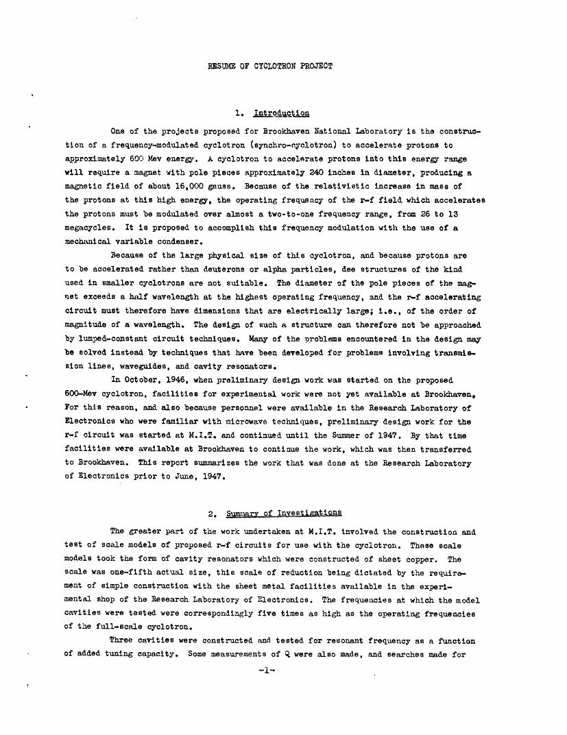
The design of the first and second cavities is illustrated in Fig. 1. The
cavity is best regarded as a low-impedance, coaxial transmission line whose axis is
perpendicular to the magnet axis, and whose cross section has been altered to a flat
rectangle to enable the cavity to fit between the magnet pole faces. The transmission
line is resonant when somewhat less than a quarter wave long, as one end is short-circuited
and the other end is open circuited but loaded with a variable capacity. The open end of
the transmission line extends across the diameter of the magnet poles, and the r-f
voltage developed across the open end of this line when excited by an oscillator is used
to accelerate the protons.
During one half cycle of operation, a proton will travel through a 180-degree
arc of a circle in the region between the pole faces not occupied by the resonant cavity.
Then, after passing across the open end of the transmission line cavity and being
accelerated by the voltage developed across this open end, the proton will travel in the
next half cycle through an additional 180-degree arc in the field-free region inside the
inner conductor of the transmission line. At the end of that time, it will be again
accelerated by the r-f field at the open end of the cavity, which will have reversed in
direction.
The rotating condenser which modulates the resonant frequency of the cavity is
located at the open end of the cavity, and therefore is in the strong magnetic field
between the pole faces of the magnet. This location imposes some rather severe design
requirements upon the condenser, which will be discussed in greater detail in a sub-
sequent section of the report.
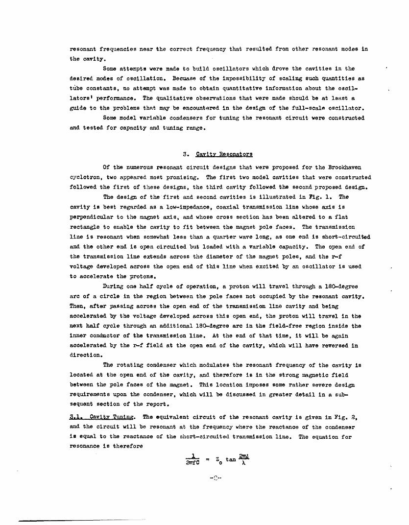
3.1. Cavity Tuning. The equivalent circuit of the resonant cavity is given in Fig. 2,
and the circuit will be resonant at the frequency where the reactance of the condenser
is equal to the reactance of the short-circuited transmission line. The equation for
resonance is therefore
_C _ Zo tan x
END CUT AWTO SHOW INNCONDUCTOR
MAGNET POLES
END VIEW OF CAVITY, SHOWING CONDENSERS
Figure 1. Proposed design of r-f circuit for cyclotron.
-J
C
CHARACTERISTIC IMPEDANCE= Z
Figure 2. Equivalent circuit of the cavity of Fig. 1.
-3-
0
OK�-
I -
where f is the resonant frequency, C the capacity of the condenser, Z the characteristic
impedance of the transmission line, X the free-space wavelength corresponding to the
resonant frequency, and R the line length.
With the first two cavities, measurements were made of resonant frequency as a
function of added capacity which checked reasonably well with the expected values. Thin
metal strips, held together with dielectric screws and separated with dielectric spacers,
were attached to the inner and outer conductors at the open end of the cavity to supply
the added capacity. Details of construction are shown in Fig. 3. The capacity was
increased by decreasing the spacing between the metal strips. After each measurement of
resonant frequency, the strips forming the added capacity were disconnected from the
cavity, and their capacity measured at 1000 cycles. Values obtained in this manner were
felt to be sufficiently accurate, for although the strips were an appreciable fraction
of a wavelength long at the resonant frequencies of the cavity, the field configuration
in the cavity for the desired mode was such that the r-f electric field between the metal
strips was uniform in both amplitude and phase.
The first test cavity, hereafter referred to as Cavity No. 1, was designed for
a spacing between magnet pole faces of 24 inches. The characteristic impedance of the
transmission line was calculated to be 4.4 ohms (See Appendix), and the line was
70 degrees long at a frequency of 130 megacycles, the scale factor of five times the
maximum operating frequency of the cyclotron.
The resonant frequency of the cavity as a function of added capacity is given in
pig. 4. The experimental data indicate the characteristic impedance to be 3.7 ohms, and
also indicate an additional capacity at the open end of about 28 AIf. The discrepancy
between theoretical and measured characteristic impedance is believed to result from
physical inaccuracies in construction of the cavity, which was made of sheet copper only
1/32 inch thick. The additional capacity was about the magnitude expected from fringing
fields at the open end of the cavity. 1
The second test cavity, Cavity No. 2, was designed for a spacing between magnet
pole faces of 30 inches. The characteristic impedance of the line was calculated to be
7.0 ohms, and the line was again 70 degrees long at 130 megacycles. The resonant
frequency as a function of added capacity is given in Fig. 4. The experimental data
indicate the characteristic impedance to be 7.0 ohms, in agreement with the theoretical
value, and the additional capacity of the fringing fields to be about 25 Elf.
The resonant frequencies of these cavities were measured by exciting the cavity
through a coupling loop with the audio-modulated oscillator of a General Radio Type 8040
Signal Generator. Resonance was detected with a pick-up probe at the open end of the
cavity which coupled a signal to a lN21B crystal detector, audio amplifier, and voltmeter.
3.2. Higher Modes. Searches were made for other modes of resonance at the same time that
the resonant frequencies of the desired mode were being determined. The flattened coaxial
-4-
1. J. R. Whinnery and H. W. Jamieson, "Equivalent Circuits for Discontinuities in Trans-mission lines", Proc. I.R.E., 2, 98 (1944).
_ _
�

SHEET COPPER
?/
DIELECTRIC SCREWS,NUTS, AND SPACERS
, SELF-TAPPING_,_5 SCREWS
-7
-METAL STRIPS
OUTER CONDUCTOR,
CENTERCONDUCTOR
Figure 3. Detail of end view of model cavity showingmetal strips and dielectric spacers thatsupply added capacity for test purposes.
4
4La
a4
FREQUENCY-MG
Figure 4. Added capacity vs. resonant frequency for ModelCavities Nos. 1 and 2.
-5-
I -
I
O
line forming the resonant circuit has a large enough mean perimeter to permit resonances
in modes other than the principal transmission line mode at frequencies not greatly differ-
ent. These modes can be identified by the non-uniform field distribution along the open
end of the cavity. Several higher modes were found, corresponding to one or more full
cycles of variation of field intensity around the perimeter of the transmission line. The
first of these higher modes was usually found at a frequency roughly 30 megacycles higher
than the resonant frequency of the principal mode, and additional modes appeared at higher
frequencies.
3.3 Shunt Impedance and Q. The calculated shunt impedance and Q of the two cavities are
plotted as functions of frequency in Figs. 5 and 6. (See Appendix for calculations) No
attempts were made to measure shunt impedance, but the Q of the cavities was determined
experimentally with the arrangement shown in Fig. 7. With 15 percent internal modulation
on Signal Generator No. 1, the model cavity was tuned to resonance by obtaining a maximum
reading on the vacuum tube voltmeter connected to the probe and crystal detector. The
modulation was then switched off, and Signal Generator No. 2 adjusted to give zero beat
with Signal Generator No. 1 as indicated by the oscilloscope and frequency meter. Modula-
tion was then switched back on Signal Generator No. 1, the gain of the amplifier was
adjusted to give full-scale reading on the voltmeter, and Signal Generator No. 1 then
detuned from resonance until the voltmeter reading fell to half scale. This indicated
that its frequency was at the half-power point of the cavity. The modulation was then
switched off again, and the frequency difference between the two signal generators read
by the audio-frequency meter. The bandwidth Af between the half-power points was
determined in this fashion, and the Q then given by the formula Q = f/Af, where f was
the resonant frequency. With this arrangement, Qs of several thousand could be measured
with an accuracy of perhaps ten per cent.
When air dielectric was used for the added condensers, the measured Q's were
somewhat greater than half the theoretically calculated values. To obtain high values of
capacity, it was necessary to use solid dielectric tape between the condenser plates,
and because of losses in the dielectric, the Q fell to about 150.
It is worth noting that the theoretical shunt impedance of these cavities varies
by about a factor of three over the operating frequency band, and that to maintain a
voltage across the open end that is invariant with frequency, the power input must change
by a corresponding factor.
3.4 Oscillators, A number of attempts were made to use the resonant cavity as the
element determining the frequency of a self-excited oscillator. One or more HY-75 triodes
were used in these experiments, operating at three to four hundred volts in the plate
supply. The field intensities produced across the open end of the cavity were investigated
qualitatively with 1/10th watt neon bulbs.
One circuit which produced an oscillator of good efficiency is shown in Fig. 8.
The mode of oscillation was very unstable, however, and depended critically on lead
lengths. For example, in one experiment, if the lead connecting the grid leak condenser
to the cavity was lengthened by less than an inch, the operating frequency would ump
-6-

12 14 16 18 20 22 24 26 28
FREQUENCY - MO
Figure 5. Theoretical Q as a function of frequency forfull scale versions of Cavities Nos. 1 and 2.
010
0
2xI-w0w;50w
z
120 _
CAVITY NO. 2
o CAVITY NO.I
20
10 I1 14 16 18 20 22 24 26
FREQUENCY-MO
Figure 6. Shunt impedance as a function of frequency forthe full-scale versions of Cavities Nos. 1 and 2.
_,7-
2i
I?
x0a
18
16 \CAVITY N0.2
14-
12
I0
'CAVITY NO.I8
6
4
2
n I I I I II0
------- I-. - - -- ,---yl-*- II_ _ I_-
I
I
28

804 CSIGNAL
GENERATOR I
I -CAVITY
804 CSIGNAL
GENERATOR2
XTAL AUDIO-FREQ.MIXER METER
OSCILLOSCOPE
ZJ D EXTAL AUDIO VTVMI~~~~~~VV
PICK-UP PROBE
Figure 7. Block diagram of equipment usedfor measurement of cavity Q.
TRANSMISSION LINE CAVITY
Y-75
Figure 8. Experimental oscillator circuit,equivalent to Hartley oscillator.
-8-
r
L
- --
.

from 155 to 216 megacycles, and the field distribution across the open end of the cavity
would change greatly, the change indicating a different mode of resonance in the cavity.
This effect was not exceptional. By careful adjustment of lead lengths, and of the loca-
tion of the plate and filament taps on the center conductor of the transmission line, the
cavity could be made to oscillate in what appeared to be the desired principal mode.
Because of the loading effect of the vacuum tube circuit, the frequency of oscillation
frequently differed by a number of megacycles from the resonant frequency of the cavity
itself. Also the vacuum tube and associated circuit appeared to distort seriously the
field pattern inside the cavity, for even with what appeared to be principal mode, the
field was frequently not uniform across the open face of the cavity, but tapered in
intensity toward one end or the other. The higher modes of oscillation which frequently
were found were similarly distorted.
As a continuously variable condenser that tuned the cavity over the required
range was not installed, measurements could only be made with fixed values of capacity
across the open end of the cavity. The optimum adjustments were different for dif-
ferent values of capacity.
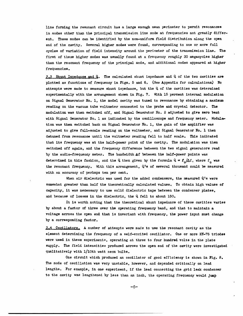
Another oscillating circuit that appeared more promising is shown in Fig. 9.
This is essentially a tuned-plate, tuned-grid oscillator, in which the cavity forms the
plate circuit. The tuned grid circuit helps to prevent the oscillator from operating at
one of the undesired, higher modes of the cavity at a different frequency. This circuit
has the obvious disadvantage that during the modulation cycle, the plate circuit, which
is the cavity, and the grid circuit, which is external to the cavity, must be constructed
so that the tuning approximately tracks over the range of operating frequency.
This circuit was much more successful than the previous one in preventing
oscillation at higher modes. In addition, the distortions of the field inside the
cavity appeared to be considerably reduced. The reasons for this latter result are not
fully understood, and the effect may be only the result of the particular construction
that was used.
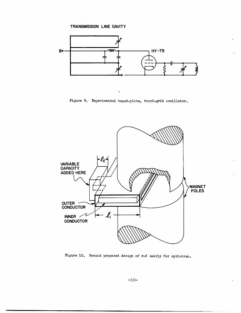
3.5 The Third ExDerimental Cavity. The third model cavity that was constructed was of a
design different from the first two, and is shown in Fig. 10. It is effectively a half-
wave transmission line, open-circuited at both ends. The resonant frequency of the line
is tuned by a variable capacity at one end of the line. This end of the line is not
between the magnet pole faces, and the rotating condenser is therefore not in a region
of strong magnetic field. This is the principal advantage of this type of cavity.
If the transmission line were of uniform characteristic impedance throughout
its length, it could not be tuned by a condenser at one end over more than a two-to-one
frequency range. If the added capacity were zero, the line would be a half wave long at
the resonant frequency. As the capacity was increased toward infinity, the resonant
frequency would decrease, but not below the point where the line was a quarter of a
wavelength long at resonance.
The tuning range may be increased by making a short section of the line
adjacent to the variable condenser of considerably higher characteristic impedance. This
-9-
_1__ -1_1_·.__111_1�·1_--_1111 � _�11�1 � I -·II
TRANSMISSION LINE CAVITY
I i~~~
I----T
2
UV_7 K
- *IS
+8
Figure 9. Experimental tuned-plate, tuned-grid oscillator.
POLES
INNER -/ '-
CONDUCTOR
Figure 10. Second proposed design of r-f cavity for cyclotron.
-10-
!
| So g * * *
ww exam·You M .-, 11 %O
(

is mechanically feasible because the section of line adjacent to the variable condenser
is not confined between the magnet pole faces. The equivalent circuit of the complete
model cavity as constructed is shown in Fig. 11. The equivalent capacity at the unction
of the two sections of transmission line results from the field distortions at this dis-
continuity.
The resonant frequency of this circuit is most readily calculated by summing to
zero the admittances at the unction of the two sections of transmission line. The tuning
curve calculated in this manner is plotted in Fig. 12, along with the experimentally
determined curve of resonant frequency versus added tuning capacity. The discrepancy
between the two curves is primarily the result of inaccuracy in the assumed value of
discontinuity capacity at the juction of the two sections of transmission line. It is
seen from the experimental curve that a tuning range of 130 to 65 megacycles is covered
by a capacity variation in the ratio of 12:1. This required capacity ratio can be further
reduced by more careful choice of the cavity dimensions.
The calculated Q and shunt impedance of the full-scale version of this model
cavity are given in Figs. 13 and 14. Two curves are given for shunt impedance, one
referring to the end of the cavity at which the variable condenser is located, and the
second' curve referring to the other, open end of the cavity, across which the voltage is
developed that accelerates the protons. With suitable shielding to preventradiation from
the model cavity, the Q was roughly measured to be of the order of 5000 at several points
over the frequency band.
No attempts were made to construct an oscillator for this third cavity.
3A6. Oomparison of Desins. Each of the two designs tested has certain advantages over
the other, and the final choice will not be made until more information has been obtained
upon which a sound decision may be based.
The first design has the advantage of structural simplicity. The cavity is
smaller, and the center conductor may be supported by cantilever beams fastened at the
short-circuited end of the line. With the second design, the center conductor must be
supported on insulators, which will be required to withstand perhaps ten or twenty
thousand volts at high radio frequencies without excessive heating while located in a
vacuum.
The principal disadvantage of the first design is that the rotating condenser
is located in a region of strongmagnetic field, and must be fitted into a rather confined
space. The second design has the condenser outside of the magnetic field.
It will probably be simpler to design a suitable oscillator for the first
design. With the second design, the voltage node inside the cavity shifts in position
with changing frequency.
4. Design of Condensers
The design of a suitable condenser for the half-wave type of cavity offers no
particularly difficult problems, as the condenser is located outside of the region of
1. Whinnery and Jamieson, loc. cit.
-1I-
- � � -- - � I . - � - ----- - - __ � -

' TUNABLE CAPACITY - DISCONTINUITY CAPACITI
Figure 11. Equivalent circuit of the cavity of Fig. 10.
40
ES
50 60 70 80 90 100 110 120 130 140 150 160
FREQUENCY- MC
Figure 12. Added capacity vs. resonant frequency for Model Cavity No. 3.
-12-
.0Q.
0
0aIJJ~0~<1
112P
z -

12 14 16 18 20 22 24 26 28
FREQUENCY-MG
Figure 13. Theoretical Q as a function of frequency forthe full-scale version of Cavity No. 3.
12 14 16 18 20 22 24 26 28 30 32
FREQUENCY - MO
Figure 14. Theoretical shunt impedance as a function of fre-quency for the full-scale version of Cavity No. 3.
-13-
i
0X
0
3
20
10
v0I
4(O0
00
O0)Oo
I ICONDENSER END ,
/ END BETWEEN MAGNET POLESEND BETWEEN MAGNET POLES
o3
Cn
,2(I" 2(0z
I
0IC
I
I~
I
I I I
11_�
I
.f- L. A -
_ ...-
I I I, .- , m, Im
--- ----- · ~-- 1;...-rmY_ · W PI· · · _·01·-·1·I_ --
,,., A
vv
I
)

strong magnetic field, and there is ample space available. With the quarter-wave design,
illustrated in Fig. 1, the condenser is required to rotate at a speed of perhaps 3600 rpm
in a magnetic field of at least 16,000 gauss, and this gives rise to the possibility of
eddy current losses which may consume a great amount of power.
The losses may be particulary large if the rotor blades are mounted on a metal1
shaft, and a dielectric shaft would be preferable from this standpoint if a material of
suitable electrical and mechanical properties can be found. Some tests have been made of
a silicone-bonded fiberglass plastic for this purpose. The electrical properties seem
wholly satisfactory, as pieces of the material inserted into the model cavity to simulate
the condenser shafts did not noticeably lower the Q of the cavity. It is doubtful,
however, whether the material possesses the requisite mechanical strength to resist the
torsional stress it will encounter.
In order to reduce the eddy current losses in the rotor blades, the blades must
be exceedingly thin. Experiments at the University of California have shown that eddy
current losses in the blades will be of the order of many kilowatts if the blades are
constructed of 1/32 inch thick copper. It has been proposed for this design to use
blades of stainless steel, thinly plated with copper, and perhaps even less than 1/32 of
an inch in thickness. Blades of this design would probably have to be stiffened by suit-
able corrugations or otherwise for mechanical strength, but the total losses in the
blades would be of the order of a kilowatt or less.
The first proposed construction of the condenser was the butterfly condenser
shown in Fig. 15, and the first model condensers constructed were of this type. These
model condensers had full size plates, but only about ten rotor blades. The first model
condensers were constructed for the design of Cavity No. 1, with a spacing of six inches
available between inner and outer conductors. It was found that with the given cavity
dimensions, it was difficult to design a condenser, even with clearances between blades
as low as 5 mm, that fitted into the available space and that met the requirements of
maximum capacity and ratio of maximum to minimum capacity imposed by the cavity dimen-
sions. This clearance was the minimum that seemed practical, because of construction
difficulties and the possibility of thermal expansion of the rotor shafts during opera-
tion of the cyclotron. By lengthening the cavity, the maximum required capacity could
have been reduced, but the required ratio of maximum to minimum capacity would have been
increased. The cavity design had originally been based on assumptions of a capacity
ratio of ten to one, plus an added fixed capacity from fringing fields of 120 Wf in the
full-scale cavity. These assumptions resulted in a required maximum tuning capacity of
about 4000 Airf for resonance at 13 Mc. It was found experimentally that the assumed
capacity ratio of ten to one was not met with spacings between condenser blades in excess
of 6 mm.
The importance of attaining a high ratio between maximum and minimum tuning
capacity should be emphasized. With a circuit of this type, the capacity ratio must
-14-
1. N. H. Frank, "Eddy Current Losses in a Conducting Shaft Rotating in a Magnetic Field",R.L.E. Report No. 23, Nov. 20, 1946.

figure 15. First proposed design for condenser for cavity of Figure 1.Oondenser shafts to extend along entire face of cavity, withblades approximately uniformly spaced.
/Air->0
0-
Figure 16. Second proposed design of variable condenser forcavity of Figure 1.
-15-
_UI__Y____IIIIIII_1^··ll��n�·-··-1�·- ·i�Oi*U�-�.Y·l*�l III_�II-LVUII^�.... .-..- __F11__11.1- . 1__��1__ 1-.�-___1-�-__(__11(--YI

always exceed the square of the desired ratio of maximum to minimum operating frequency,
and this limiting value can only be approached as the cavity length, and consequently its
shunt impedance, approach zero. As the length of the cavity approaches a quarter wave-
length at the highest operating frequency, the capacity ratio will approach infinity. It
is obvious that a compromise must be made between the shunt impedance of the cavity, the
maximum tuning capacity, and the tuning ratio of the condenser. With the spacing between
magnet poles limited to 24 inches, it was difficult to obtain a satisfactory design.
The most satisfactory solution was to increase the spacing between magnet poles
to 30 inches. This will require a greater magnetomotive force to produce a given magnetic
field, but the increased size of the r-f circuit will increase its efficiency. More
important, the effective inductance of the cavity is increased by its greater volume, and
the required maximum tuning capacity is correspondingly reduced. Also, more space is
available for the tuning condenser, making it easier to attain the maximum required
capacity without too great a reduction in the spacing between condenser plates. Cavity
No. 2 was made the same length as Cavity No. 1, but designed for the greater spacing
between pole faces. The capacity required to tune Cavity No. 2 to the lowest operating
frequency was reduced to about two-thirds of the capacity required for Cavity No. 1.
At about this time, the condenser design shown in Fig. 16 was suggested, which
allowed a greater area for the condenser plates, and a correspondingly greater capacity.
The most satisfactory model condenser had the dimensions indicated in Fig. 17. The
ratio between maximum and minimum capacity was about eleven to one, and with ten rotor
blades, the maximum capacity was 140 O4f. This is great enough to permit the maximum
required capacity to be readily attained, with ample room for bearings on the rotor
shaft and for the ion source in the center.
Ackqwgledgement. The work outlined in this report was carried out at the Research
Laboratories of Electronics, Massachusetts Institute of Technology, ointly by Mr. Martin
Plotkin, of Brookhaven Laboratory, and the author. The work was under the general
direction of Professor M. S. Livingston, and the immediate supervision of Professor
G. G. arvey, and the project is presently being continued at BrookhavenLaboratory under
the direction of Professor Livingston.
-16-
I _

Detail of a proposed design of one of the cavity tuningcondensers. Spacing between rotor and stator blades is1/4 in. Maximum to minimum capacity ratio is 10.5.(Note: The final design developed at Brookhaven main-tained the 70° angles and the 1/4-in. condenser bladespacing, but reduced the spacing between inner andouter conductors to 8 in.).
-17-
Pigure 17.
------ _1II__ II_ IIIl~·Yll~ mI ~ C· I~I~-_ U_··___

APPENDIX
Methods of calculating various parameters of the model cavities:
Characteristic Impedance. To calculate the characteristic impedance of the coaxial lines
of rectangular cross section, use the approximate formula:
Z = 377 spacin between conductors ohms.o mean perimeter
Resistance per Unit Length. In high-frequency transmission lines, the effective resistance
is the same as if the current were concentrated uniformly in a surface layer of thickness
equal to the skin depth 6. The skin depth is given by
9J = | 10 , em p = resistivity in ohms-cm
'211z 2hw w = angular frequency
and the resistance per unit length is
R = ( perimeter of inner conductor perimeter of outer conductor )
Inductance per Unit Length. The inductance per unit length of the transmission line is
given approximately by the formula
'LO x spacing between conductorsL =
mean perimeter
where o is the permeability of free space (rationalized MKS units 4b = 1.257 x 10-
henries/meter).
Resonant Frequency as a Function of Capacity. For cavities Nos. 1 and 2, the equivalent
circuit may be drawn as in Fig. 2, and the resonant frequency is obtained by equating the
input admittance of the transmission line to the negative of the condenser admittance.
For Cavity No. 3, the equivalent circuit is given in Fig. 11. The resonant
frequency as a function of capacity is best calculated by breaking the circuit at the left
of the discontinuity capacity at the junction of the two transmission lines. After
assuming the resonant frequency, the admittance looking to the right can be calculated by
conventional transmission line theory. The negative of this admittance is equated to the
admittance seen looking to the left. The tuning capacity at the end of the left-hand
section of the line may then be calculated, again by conventional transmission line theory.
The value of discontinuity capacity at the Junction of the two sections of
transmission line may be only roughly estimated, because of the complexity of this
Juction. For the model cavity, this capacity was assumed to be 60 4.f, or 300 Elf in the
full-scale cavity.
-18-
......

Cavity Q. The Q of a short section of transmission line of length d is given by
Q `R do
where R is the resistance per unit length, L the inductance per unit length, and w the
angular frequency. This expression may be rewritten in the following form:
RI2 w(stored energy)2 Rde power dissipated
For a resonant system composed of sections of transmission line, the Q of the over-all
system may be obtained by integrating the above expression along the length of the trans-
mission line:
JfLI2 &df =
For a resonant system like Cavities No. 1 and 2, where only a single section of trans-
mission line is involved, the ratio of the two integrals is the same as the ratio of their
integrands, For a composite system, such as in Cavity No. 3, the line parameters as well
as the current are functions of position, and the integrations must be carried out.
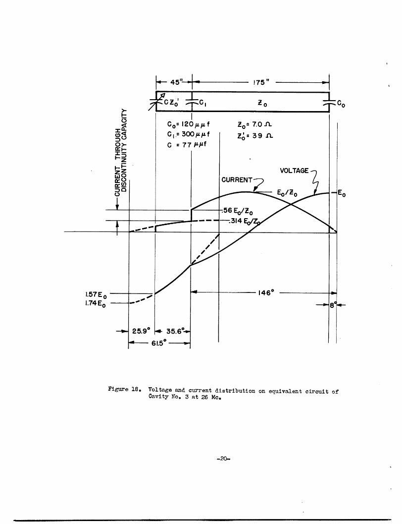
The current distribution along the line is readily obtained from the calcula-
tions for resonant frequency for the cavity. The current and voltage distribution at a
frequency of 26 Mec are plotted in Fig. 18 to illustrate the results of a calculation of
this sort.
Shunt Impedance. To calculate shunt impedance of the cavities, use the formula
aR _(voltae)2 V2
sh power input 2RI2 &d
As in the calculations for Q, the integration is carried out along the length of the
transmission system. This method may be used for all cavities. In Cavities Nos. 1 and 2,
it is convenient to choose for voltage the voltage developed across the open end of the
transmission line. For Cavity No. 3, two values for shunt impedance may be obtained, one
referring to the voltage at one end of the cavity, the second referring to the voltage
developed at the other end.
-19 -
"L**r�·---rs*-··-rrr^fllP-�"IIYr�ll�l�-- ·- ·a�---�·--�---p_··.·-- .r�---�-r�-u�-a�-�sarl·--�-_�-----·---- -_
4- 45 ' 175" A
Figure 18. Voltage and current distribution on equivalent circuit ofCavity No. 3 at 26 Mc.
-20-
___- _ ��.