RESTRAINTS SRS A - navlife.com.au · b1049 driver air bag module b1050 b1051 b1052 b1054 b1055...
38
SRS-1 RESTRAINTS C D E F G I J K L M SECTION SRS A B SRS N O P CONTENTS SUPPLEMENTAL RESTRAINT SYSTEM (SRS) SERVICE INFORMATION ........................... 2 DTC INDEX ......................................................... 2 B1001-B1015 ........................................................... 2 B1042-B1057 ........................................................... 2 B1058-B1073 ........................................................... 3 B1074-B1089 ........................................................... 3 B1202-B1210 ........................................................... 3 PRECAUTIONS .................................................. 4 Precaution for Supplemental Restraint System (SRS) "AIR BAG" and "SEAT BELT PRE-TEN- SIONER" .................................................................. 4 Precaution for SRS "AIR BAG" and "SEAT BELT PRE-TENSIONER" Service ..................................... 4 Service ..................................................................... 4 PREPARATION .................................................. 6 Special Service Tool ................................................ 6 Commercial Service Tool ......................................... 6 SUPPLEMENTAL RESTRAINT SYSTEM (SRS) .................................................................. 8 SRS Configuration ................................................... 8 Front Seat Belt Pre-tensioner with Load Limiter ...... 8 Direct-Connect SRS Component Connectors .......... 8 TROUBLE DIAGNOSIS ....................................10 Trouble Diagnosis Introduction .............................. 10 SRS Component Parts Location ............................ 12 Wiring Diagram - SRS - .......................................... 13 CONSULT-III Function ........................................... 14 Self-Diagnosis Function (Without CONSULT-III) .... 15 SRS Operation Check ............................................16 Trouble Diagnosis with CONSULT-III .....................17 Trouble Diagnosis without CONSULT-III ................19 Trouble Diagnosis: "AIR BAG" Warning Lamp Does Not Turn OFF ................................................20 Trouble Diagnosis: "AIR BAG" Warning Lamp Does Not Turn ON ..................................................21 DRIVER AIR BAG MODULE ............................ 22 Component Parts Location .....................................22 Removal and Installation ........................................22 SPIRAL CABLE ................................................ 24 Component Parts Location .....................................24 Removal and Installation ........................................24 FRONT PASSENGER AIR BAG MODULE ...... 27 Removal and Installation ........................................27 FRONT SEAT BELT PRE-TENSIONER ........... 30 Removal and Installation ........................................30 DIAGNOSIS SENSOR UNIT ............................. 31 Component Parts Location .....................................31 Removal and Installation ........................................31 DISPOSAL OF AIR BAG MODULE AND SEAT BELT PRE-TENSIONER ........................ 33 Caution for Air Bag Module and Seat Belt Pre-ten- sioner ......................................................................33 COLLISION DIAGNOSIS .................................. 38 For Frontal Collision ...............................................38
-
Upload
phungthien -
Category
Documents
-
view
229 -
download
1
Transcript of RESTRAINTS SRS A - navlife.com.au · b1049 driver air bag module b1050 b1051 b1052 b1054 b1055...
RESTRAINTS
C
D
E
SECTION SRSA
B
SUPPLEMENTAL RESTRAINT SYSTEM (SRS)
F
G
I
J
K
L
M
RS
N
O
P
CONTENTS
S
SERVICE INFORMATION ............................ 2
DTC INDEX .......................................................... 2B1001-B1015 ............................................................2B1042-B1057 ............................................................2B1058-B1073 ............................................................3B1074-B1089 ............................................................3B1202-B1210 ............................................................3
PRECAUTIONS ................................................... 4Precaution for Supplemental Restraint System (SRS) "AIR BAG" and "SEAT BELT PRE-TEN-SIONER" ...................................................................4Precaution for SRS "AIR BAG" and "SEAT BELT PRE-TENSIONER" Service ......................................4Service ......................................................................4
PREPARATION ................................................... 6Special Service Tool .................................................6Commercial Service Tool ..........................................6
SUPPLEMENTAL RESTRAINT SYSTEM (SRS) ................................................................... 8
SRS Configuration ....................................................8Front Seat Belt Pre-tensioner with Load Limiter .......8Direct-Connect SRS Component Connectors ...........8
TROUBLE DIAGNOSIS .....................................10Trouble Diagnosis Introduction ...............................10SRS Component Parts Location .............................12Wiring Diagram - SRS - ...........................................13CONSULT-III Function ............................................14Self-Diagnosis Function (Without CONSULT-III) ....15
SRS Operation Check .............................................16Trouble Diagnosis with CONSULT-III ......................17Trouble Diagnosis without CONSULT-III .................19Trouble Diagnosis: "AIR BAG" Warning Lamp Does Not Turn OFF .................................................20Trouble Diagnosis: "AIR BAG" Warning Lamp Does Not Turn ON ...................................................21
DRIVER AIR BAG MODULE ............................22Component Parts Location ......................................22Removal and Installation .........................................22
SPIRAL CABLE ................................................24Component Parts Location ......................................24Removal and Installation .........................................24
FRONT PASSENGER AIR BAG MODULE ......27Removal and Installation .........................................27
FRONT SEAT BELT PRE-TENSIONER ...........30Removal and Installation .........................................30
DIAGNOSIS SENSOR UNIT .............................31Component Parts Location ......................................31Removal and Installation .........................................31
DISPOSAL OF AIR BAG MODULE AND SEAT BELT PRE-TENSIONER ........................33
Caution for Air Bag Module and Seat Belt Pre-ten-sioner .......................................................................33
COLLISION DIAGNOSIS ..................................38For Frontal Collision ................................................38
SRS-1

DTC INDEX
< SERVICE INFORMATION >SERVICE INFORMATIONDTC INDEX
B1001-B1015 INFOID:0000000003950650
B1042-B1057 INFOID:0000000003950651
DTC Items (CONSULT screen terms) Reference
B1001
DIAGNOSIS SENSOR UNIT SRS-17, "Trouble Diagnosis with CONSULT-III"
B1002
B1003
B1004
B1005
B1006
B1007
B1008
B1009
B1010
B1011
B1012
B1013
B1014
B1015
DTC Items (CONSULT screen terms) Reference
B1042
DIAGNOSIS SENSOR UNIT
SRS-17, "Trouble Diagnosis with CONSULT-III"
B1043
B1044
B1045
B1046
B1047
B1049
DRIVER AIR BAG MODULE
B1050
B1051
B1052
B1054
B1055
B1056
B1057
SRS-2
DTC INDEX
C
D
E
F
G
I
J
K
L
M
A
B
RS
N
O
P
< SERVICE INFORMATION >
S
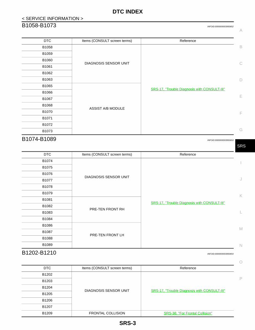
B1058-B1073 INFOID:0000000003950652
B1074-B1089 INFOID:0000000003950653
B1202-B1210 INFOID:0000000003950654
DTC Items (CONSULT screen terms) Reference
B1058
DIAGNOSIS SENSOR UNIT
SRS-17, "Trouble Diagnosis with CONSULT-III"
B1059
B1060
B1061
B1062
B1063
B1065
ASSIST A/B MODULE
B1066
B1067
B1068
B1070
B1071
B1072
B1073
DTC Items (CONSULT screen terms) Reference
B1074
DIAGNOSIS SENSOR UNIT
SRS-17, "Trouble Diagnosis with CONSULT-III"
B1075
B1076
B1077
B1078
B1079
B1081
PRE-TEN FRONT RHB1082
B1083
B1084
B1086
PRE-TEN FRONT LHB1087
B1088
B1089
DTC Items (CONSULT screen terms) Reference
B1202
DIAGNOSIS SENSOR UNIT SRS-17, "Trouble Diagnosis with CONSULT-III"
B1203
B1204
B1205
B1206
B1207
B1209 FRONTAL COLLISION SRS-38, "For Frontal Collision"
SRS-3

PRECAUTIONS
< SERVICE INFORMATION >PRECAUTIONS
Precaution for Supplemental Restraint System (SRS) "AIR BAG" and "SEAT BELT PRE-TENSIONER" INFOID:0000000003950655
The Supplemental Restraint System such as “AIR BAG” and “SEAT BELT PRE-TENSIONER”, used alongwith a front seat belt, helps to reduce the risk or severity of injury to the driver and front passenger for certaintypes of collision. Information necessary to service the system safely is included in the “SUPPLEMENTALRESTRAINT SYSTEM” and “SEAT BELTS” of this Service Manual.WARNING:• To avoid rendering the SRS inoperative, which could increase the risk of personal injury or death in
the event of a collision which would result in air bag inflation, all maintenance must be performed byan authorized NISSAN/INFINITI dealer.
• Improper maintenance, including incorrect removal and installation of the SRS, can lead to personalinjury caused by unintentional activation of the system. For removal of Spiral Cable and Air BagModule, see the “SUPPLEMENTAL RESTRAINT SYSTEM”.
• Do not use electrical test equipment on any circuit related to the SRS unless instructed to in thisService Manual. SRS wiring harnesses can be identified by yellow and/or orange harnesses or har-ness connectors.
PRECAUTIONS WHEN USING POWER TOOLS (AIR OR ELECTRIC) AND HAMMERSWARNING:• When working near the Air Bag Diagnosis Sensor Unit or other Air Bag System sensors with the
ignition ON or engine running, DO NOT use air or electric power tools or strike near the sensor(s)with a hammer. Heavy vibration could activate the sensor(s) and deploy the air bag(s), possiblycausing serious injury.
• When using air or electric power tools or hammers, always switch the ignition OFF, disconnect thebattery, and wait at least 3 minutes before performing any service.
Precaution for SRS "AIR BAG" and "SEAT BELT PRE-TENSIONER" ServiceINFOID:0000000003950656
• Never use electrical test equipment to check SRS circuits unless instructed to in this Service Manual.• Before servicing the SRS, turn ignition switch OFF, disconnect battery negative terminal and wait at least 3
minutes.For approximately 3 minutes after the battery negative terminal is removed, it is still possible for the air bagand seat belt pre-tensioner to deploy. Therefore, never work on any SRS connectors or wires until at least 3minutes have passed.
• Diagnosis sensor unit must always be installed with their arrow marks “⇐” pointing towards the front of thevehicle for proper operation. Also check diagnosis sensor unit for cracks, deformities, or rust before installa-tion and replace as required.
• The spiral cable must be aligned with the neutral position since its rotations are limited. Never attempt to turnsteering wheel or column after removal of steering gear.
• Handle air bag module carefully. Always place driver and front passenger air bag modules with the pad sidefacing upward.
• Conduct self-diagnosis to check entire SRS for proper function after replacing any components.• After air bag inflates, the front instrument panel assembly should be replaced if damaged.• Always replace instrument panel pad following front passenger air bag deployment.
Service INFOID:0000000004068197
• Never use electrical test equipment to check SRS circuits unless instructed to in this Service Manual.• Before servicing the SRS, turn ignition switch OFF, disconnect both battery cables and wait at least 3 min-
utes.For approximately 3 minutes after the cables are removed, it is still possible for the air bag and seat belt pre-tensioner to deploy. Therefore, never work on any SRS connectors or wires until at least 3 minutes haveelapsed.
• Diagnosis sensor unit must always be installed with their arrow marks “⇐” pointing towards the front of thevehicle for proper operation. Also check diagnosis sensor unit for cracks, deformities, or rust before installa-tion and replace as required.
SRS-4
PRECAUTIONS
C
D
E
F
G
I
J
K
L
M
A
B
RS
N
O
P
< SERVICE INFORMATION >
S
• The spiral cable must be aligned in the neutral position since its rotations are limited. Never turn steeringwheel and column after removal of steering gear.
• Handle air bag module carefully. Always place driver and front passenger air bag modules with the pad sidefacing upward and seat mounted front side air bag module standing with the stud bolt side facing downward.
• Perform self-diagnosis to check entire SRS for proper functioning after replacing any components.• After air bag deploys, the front instrument panel assembly should be replaced if damaged.• Always replace instrument panel pad following front passenger air bag deployment.
SRS-5

PREPARATION
< SERVICE INFORMATION >PREPARATION
Special Service Tool INFOID:0000000003950657
Commercial Service Tool INFOID:0000000003950658
Tool numberTool name
Description
KV99105300Air bag module bracket
Anchors the air bag module
KV99106400Deployment tool
Disposes the air bag module and front seat belt pre-tensioner
KV99109700• Deployment tool adapter for front
seat belt pre-tensioner• Deployment tool adapter for driver
air bag module
• Connects the deployment tool and front seat belt pre-tensioner
• Connects between the deployment tool and driver air bag module
KV99108300Deployment tool adapters for front passenger air bag module
Connects the deployment tool and front pas-senger air bag module
S-NT354
S-NT357
SHIA0038J
ZZA1166D
SRS-6
PREPARATION
C
D
E
F
G
I
J
K
L
M
A
B
RS
N
O
P
< SERVICE INFORMATION >
S
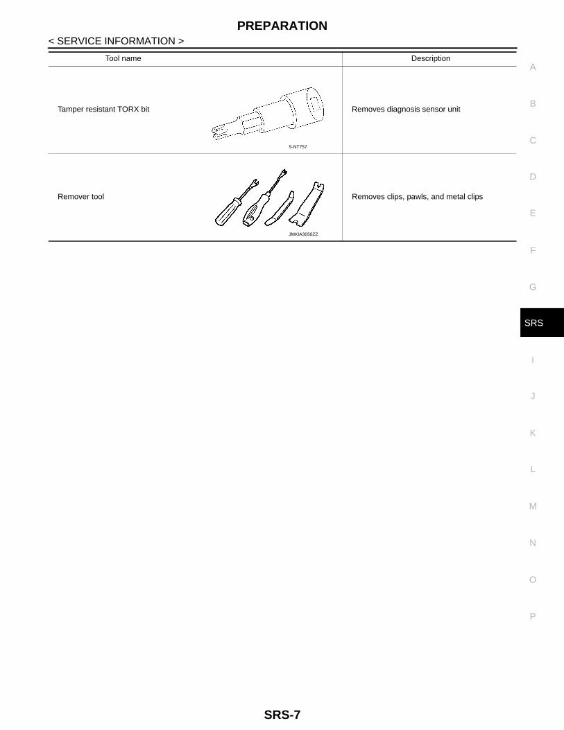
Tool name Description
Tamper resistant TORX bit Removes diagnosis sensor unit
Remover tool Removes clips, pawls, and metal clips
S-NT757
JMKIA3050ZZ
SRS-7

SUPPLEMENTAL RESTRAINT SYSTEM (SRS)
< SERVICE INFORMATION >SUPPLEMENTAL RESTRAINT SYSTEM (SRS)
SRS Configuration INFOID:0000000003950659
The air bag deploys if the air bag diagnosis sensor unit is activated while the ignition switch is in the ON orSTART position.The collision modes for which supplemental restraint systems are activated are different among the SRS sys-tems. For example, the driver air bag module, front passenger air bag module and front seat belt pre-tension-ers are activated in a frontal collision but not in a side collision.SRS configurations for some collision modes are as follows:
Front Seat Belt Pre-tensioner with Load Limiter INFOID:0000000003950660
The seat belt pre-tensioner system with load limiter is installed forboth the driver seat and the front passenger seat. It operates simul-taneously with the SRS air bag system in the event of a frontal colli-sion with an impact exceeding a specified level.When the frontal collision with an impact exceeding a specified leveloccurs, seat belt slack resulting from clothing or other factors isimmediately taken up by the pre-tensioner. Vehicle passengers aresecurely restrained.When passengers in a vehicle are thrown forward in a collision andthe restraining force of the seat belt exceeds a specified level, theload limiter permits the specified extension of the seat belt by thetwisting of the ELR shaft, and a relaxation of the chest-area seat beltweb tension while maintaining force.
Direct-Connect SRS Component Connectors INFOID:0000000003950661
The following SRS components use direct-connect style harness connectors.• Driver air bag module• Front passenger air bag module• Front LH seat belt pre-tensioner• Front RH seat belt pre-tensioner
MHIB0119E
SRS configuration Frontal collision Left side collision Right side collision
Driver air bag module × — —
Front passenger air bag module × — —
Front LH seat belt pre-tensioner × — —
Front RH seat belt pre-tensioner × — —
WHIA0225E
SRS-8
SUPPLEMENTAL RESTRAINT SYSTEM (SRS)
C
D
E
F
G
I
J
K
L
M
A
B
RS
N
O
P
< SERVICE INFORMATION >
S
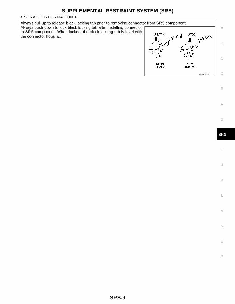
Always pull up to release black locking tab prior to removing connector from SRS component.Always push down to lock black locking tab after installing connectorto SRS component. When locked, the black locking tab is level withthe connector housing.
WHIA0103E
SRS-9
TROUBLE DIAGNOSIS
< SERVICE INFORMATION >TROUBLE DIAGNOSIS
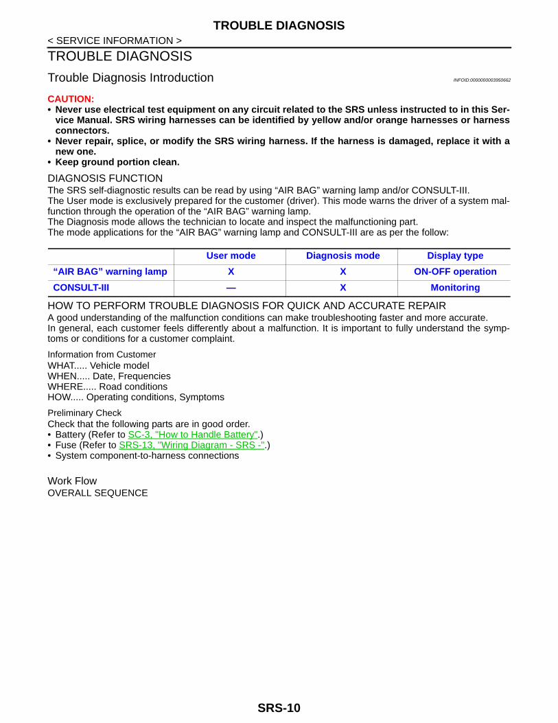
Trouble Diagnosis Introduction INFOID:0000000003950662
CAUTION:• Never use electrical test equipment on any circuit related to the SRS unless instructed to in this Ser-
vice Manual. SRS wiring harnesses can be identified by yellow and/or orange harnesses or harnessconnectors.
• Never repair, splice, or modify the SRS wiring harness. If the harness is damaged, replace it with anew one.
• Keep ground portion clean.
DIAGNOSIS FUNCTIONThe SRS self-diagnostic results can be read by using “AIR BAG” warning lamp and/or CONSULT-III.The User mode is exclusively prepared for the customer (driver). This mode warns the driver of a system mal-function through the operation of the “AIR BAG” warning lamp.The Diagnosis mode allows the technician to locate and inspect the malfunctioning part.The mode applications for the “AIR BAG” warning lamp and CONSULT-III are as per the follow:
HOW TO PERFORM TROUBLE DIAGNOSIS FOR QUICK AND ACCURATE REPAIRA good understanding of the malfunction conditions can make troubleshooting faster and more accurate.In general, each customer feels differently about a malfunction. It is important to fully understand the symp-toms or conditions for a customer complaint.
Information from CustomerWHAT..... Vehicle modelWHEN..... Date, FrequenciesWHERE..... Road conditionsHOW..... Operating conditions, Symptoms
Preliminary CheckCheck that the following parts are in good order.• Battery (Refer to SC-3, "How to Handle Battery".)• Fuse (Refer to SRS-13, "Wiring Diagram - SRS -".)• System component-to-harness connections
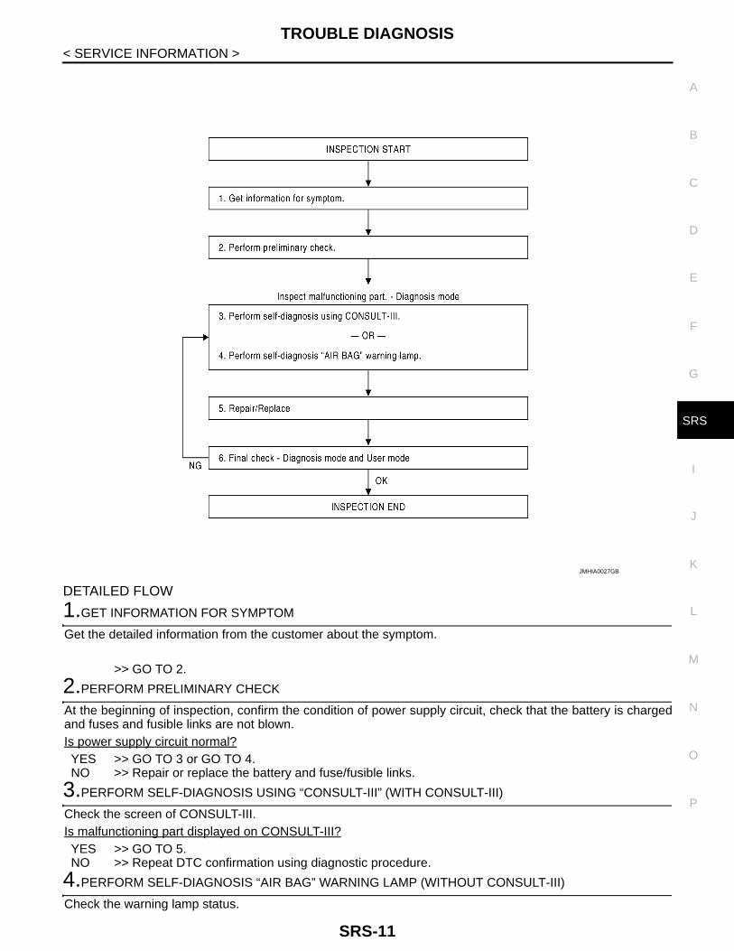
Work FlowOVERALL SEQUENCE
User mode Diagnosis mode Display type
“AIR BAG” warning lamp X X ON-OFF operation
CONSULT-III — X Monitoring
SRS-10
TROUBLE DIAGNOSIS
C
D
E
F
G
I
J
K
L
M
A
B
RS
N
O
P
< SERVICE INFORMATION >
S
DETAILED FLOW
1.GET INFORMATION FOR SYMPTOM
Get the detailed information from the customer about the symptom.
>> GO TO 2.
2.PERFORM PRELIMINARY CHECK
At the beginning of inspection, confirm the condition of power supply circuit, check that the battery is chargedand fuses and fusible links are not blown.Is power supply circuit normal?YES >> GO TO 3 or GO TO 4.NO >> Repair or replace the battery and fuse/fusible links.
3.PERFORM SELF-DIAGNOSIS USING “CONSULT-III” (WITH CONSULT-III)
Check the screen of CONSULT-III.Is malfunctioning part displayed on CONSULT-III?YES >> GO TO 5.NO >> Repeat DTC confirmation using diagnostic procedure.
4.PERFORM SELF-DIAGNOSIS “AIR BAG” WARNING LAMP (WITHOUT CONSULT-III)
Check the warning lamp status.
JMHIA0027GB
SRS-11

TROUBLE DIAGNOSIS
< SERVICE INFORMATION >Is malfunctioning part detected?YES >> GO TO 5.NO >> Repeat DTC confirmation with diagnostic procedure.5.REPAIR OR REPLACE
Repair or replace the malfunctioning part.After the malfunctioning is repaired, erase the self-diagnostic result. Refer to SRS-14, "CONSULT-III Func-tion".
>> GO TO 6.
6.FINAL CHECK DIAGNOSIS MODE AND USER MODE
Check the screen of CONSULT-III and/or Air bag warning lamp status.Are the malfunctions corrected?YES >> INSPECTION END.NO >> GO TO 3 or GO TO 4.
SRS Component Parts Location INFOID:0000000003950663
1. Front RH seat belt pre-tensioner 2. Front passenger air bag module 3. Air bag warning lamp
4. Spiral cable 5. Driver air bag module 6. Front LH seat belt pre-tensioner
7. Diagnosis sensor unit
MHIB0120E
SRS-12

TROUBLE DIAGNOSIS
C
D
E
F
G
I
J
K
L
M
A
B
RS
N
O
P
< SERVICE INFORMATION >
S
Wiring Diagram - SRS - INFOID:0000000003950664
MHWA0095E
SRS-13

TROUBLE DIAGNOSIS
< SERVICE INFORMATION >CONSULT-III Function INFOID:0000000003950665
DIAGNOSIS MODE FOR CONSULT-III• “SELF-DIAG [CURRENT]”
The current self-diagnostic results (also indicated by the number of warning lamp blinks in the Diagnosismode) are displayed on the CONSULT-III screen in real time. This refers to a malfunctioning part requiringrepair.
• “SELF-DIAG [PAST]”
MHWA0082E
SRS-14
TROUBLE DIAGNOSIS
C
D
E
F
G
I
J
K
L
M
A
B
RS
N
O
P
< SERVICE INFORMATION >
S
Diagnosis results previously stored in the memory are displayed on the CONSULT-III screen. The storedresults are not erased until memory erasing is executed.
• “TROUBLE DIAG RECORD”With TROUBLE DIAG RECORD, diagnosis results previously erased by a reset operation can be displayedon the CONSULT-III screen.
• “ECU DISCRIMINATED NO.”The diagnosis sensor unit for each vehicle model is assigned with its own, individual classification number.This number will be displayed on the CONSULT-III screen, as shown. When replacing the diagnosis sensorunit, refer to the part number for the compatibility. After installation, replacement with a correct unit can bechecked by confirming this classification number on the CONSULT-III screen.After repair, check that the discriminated number of diagnosis sensor unit installed to vehicle is the same.Refer to SRS-31, "Removal and Installation".
HOW TO CHANGE SELF-DIAGNOSIS MODE WITH CONSULT-III
From User Mode to Diagnosis ModeAfter selecting “AIR BAG” on the “SELECT SYSTEM” screen, the User mode automatically changes to theDiagnosis mode.
From Diagnosis Mode to User ModeTo return to the User mode from the Diagnosis mode, touch “BACK” key of CONSULT-III until “SELECT SYS-TEM” appears, then the diagnosis mode automatically changes to the User mode.
HOW TO ERASE SELF-DIAGNOSTIC RESULTS• “SELF-DIAG [CURRENT]”
A current self-diagnostic result is displayed on the CONSULT-III screen in real time.After the malfunction is repaired completely, no malfunction is detected on “SELF-DIAG [CURRENT]”.
• “SELF-DIAG [PAST]”Return to the “SELF-DIAG [CURRENT]” CONSULT-III screen by touching “BACK” key of CONSULT-III andselect “SELF-DIAG [CURRENT]” in SELECT DIAG MODE. Touch “ERASE” in “SELF-DIAG [CURRENT]”mode.NOTE:If the memory of the malfunction in “SELF-DIAG [PAST]” is not erased, the User mode shows the systemmalfunction by the operation of the warning lamp even if the malfunction is repaired completely.
• “TROUBLE DIAG RECORD”The memory of “TROUBLE DIAG RECORD” cannot be erased.
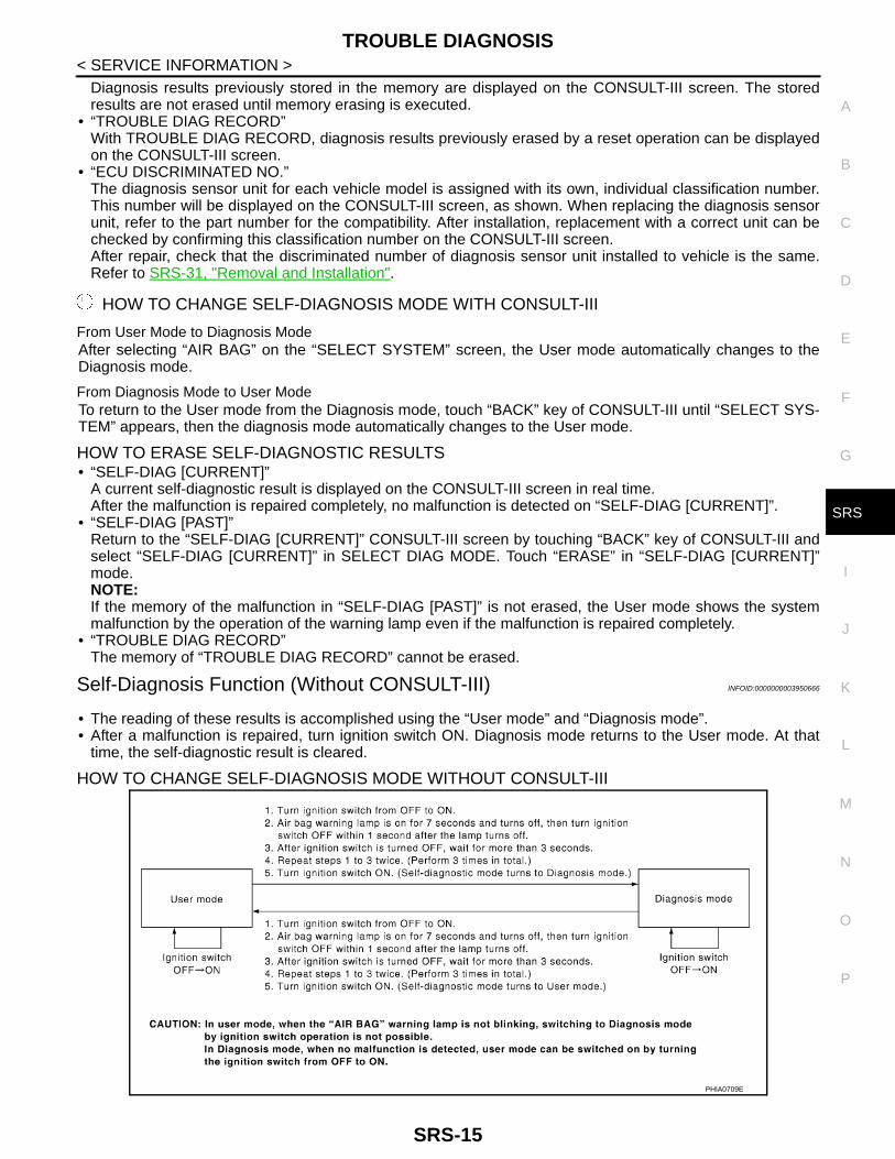
Self-Diagnosis Function (Without CONSULT-III) INFOID:0000000003950666
• The reading of these results is accomplished using the “User mode” and “Diagnosis mode”.• After a malfunction is repaired, turn ignition switch ON. Diagnosis mode returns to the User mode. At that
time, the self-diagnostic result is cleared.
HOW TO CHANGE SELF-DIAGNOSIS MODE WITHOUT CONSULT-III
PHIA0709E
SRS-15

TROUBLE DIAGNOSIS
< SERVICE INFORMATION >HOW TO ERASE SELF-DIAGNOSIS RESULTSAfter a malfunction is repaired, turn ignition switch OFF for at least one second, then back ON. the Diagnosismode returns to the User mode. At that time, the self-diagnostic result is cleared.
SRS Operation Check INFOID:0000000003950667
DIAGNOSTIC PROCEDURE
Checking Air Bag Operation by Using “AIR BAG” Warning Lamp — User Mode
1. Turn ignition switch from OFF to ON, and make sure that the air bag warning lamp blinks.2. Compare the SRS air bag warning lamp blinking pattern with the
examples.
Warning lamp examples
BF-1845D
“AIR BAG” warning lamp operation — User mode SRS condition Reference item
• No malfunction is detected.• No further action is necessary.
—
• The system is malfunctioning and needs to be repaired as indicated.
Go to SRS-17, "Trouble Diagnosis with CONSULT-III" or SRS-19, "Trouble Diagnosis without CON-SULT-III".
SHIA0011E
SHIA0012E
SRS-16

TROUBLE DIAGNOSIS
C
D
E
F
G
I
J
K
L
M
A
B
RS
N
O
P
< SERVICE INFORMATION >
S
Trouble Diagnosis with CONSULT-III INFOID:0000000003950668
DIAGNOSTIC PROCEDURE
DTC No. Index ("SELF-DIAG [CURRENT]" “SELF-DIAG [PAST]” or TROUBLE DIAG RECORD)
• Air bag is deployed.• Seat belt pre-tensioner is deployed.
Go to SRS-38, "For Frontal Colli-sion".
• Diagnosis sensor unit is malfunction-ing.
• Air bag power supply circuit is mal-functioning.
• SRS air bag warning lamp circuit is malfunctioning.
Go to SRS-20, "Trouble Diagnosis: "AIR BAG" Warning Lamp Does Not Turn OFF".
• Diagnosis sensor unit is malfunction-ing.
• Air bag warning lamp circuit is mal-functioning.
Go to SRS-21, "Trouble Diagnosis: "AIR BAG" Warning Lamp Does Not Turn ON".
“AIR BAG” warning lamp operation — User mode SRS condition Reference item
SHIA0013E
SHIA0014E
Diagnostic mode Description
SELF-DIAG RESULT The self-diagnosis result is displayed. (SELF-DIAG [CURRENT], [PAST], [RECORD])
ECU DISCRIMINATED No. The parts number of diagnosis sensor unit is displayed.
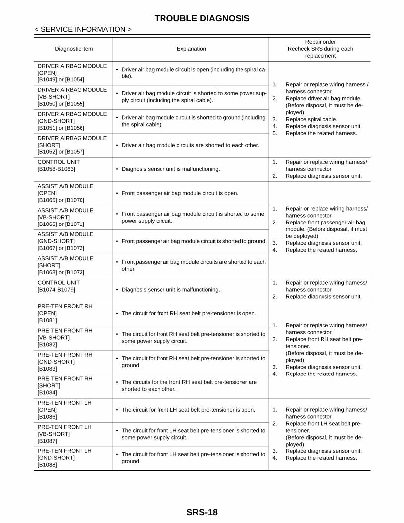
Diagnostic item ExplanationRepair order
Recheck SRS during each replacement
NO DTC IS DETECTED
When malfunction is indicated by the “AIR BAG” warning lamp in the User mode.
• Low battery voltage (Less than 9V)
• Self-diagnostic result “SELF-DIAG [PAST]” (previously stored in the memory) might not be erased after repair.
• Intermittent malfunction has been detected in the past.
Go to SRS-14, "CONSULT-III Func-tion".
• No malfunction is detected. —
CONTROL UNIT[B1001-B1015][B1042-B1047]
• Diagnosis sensor unit is malfunctioning.1. Repair or replace wiring harness/
harness connector.2. Replace diagnosis sensor unit.
SRS-17
TROUBLE DIAGNOSIS
< SERVICE INFORMATION >DRIVER AIRBAG MODULE[OPEN][B1049] or [B1054]
• Driver air bag module circuit is open (including the spiral ca-ble).
1. Repair or replace wiring harness /harness connector.
2. Replace driver air bag module. (Before disposal, it must be de-ployed)
3. Replace spiral cable.4. Replace diagnosis sensor unit.5. Replace the related harness.
DRIVER AIRBAG MODULE[VB-SHORT][B1050] or [B1055]
• Driver air bag module circuit is shorted to some power sup-ply circuit (including the spiral cable).
DRIVER AIRBAG MODULE[GND-SHORT][B1051] or [B1056]
• Driver air bag module circuit is shorted to ground (including the spiral cable).
DRIVER AIRBAG MODULE[SHORT][B1052] or [B1057]
• Driver air bag module circuits are shorted to each other.
CONTROL UNIT[B1058-B1063] • Diagnosis sensor unit is malfunctioning.
1. Repair or replace wiring harness/ harness connector.
2. Replace diagnosis sensor unit.
ASSIST A/B MODULE[OPEN][B1065] or [B1070]
• Front passenger air bag module circuit is open.
1. Repair or replace wiring harness/harness connector.
2. Replace front passenger air bag module. (Before disposal, it must be deployed)
3. Replace diagnosis sensor unit.4. Replace the related harness.
ASSIST A/B MODULE[VB-SHORT][B1066] or [B1071]
• Front passenger air bag module circuit is shorted to some power supply circuit.
ASSIST A/B MODULE[GND-SHORT][B1067] or [B1072]
• Front passenger air bag module circuit is shorted to ground.
ASSIST A/B MODULE[SHORT][B1068] or [B1073]
• Front passenger air bag module circuits are shorted to each other.
CONTROL UNIT[B1074-B1079] • Diagnosis sensor unit is malfunctioning.
1. Repair or replace wiring harness/ harness connector.
2. Replace diagnosis sensor unit.
PRE-TEN FRONT RH[OPEN][B1081]
• The circuit for front RH seat belt pre-tensioner is open.
1. Repair or replace wiring harness/ harness connector.
2. Replace front RH seat belt pre-tensioner.(Before disposal, it must be de-ployed)
3. Replace diagnosis sensor unit.4. Replace the related harness.
PRE-TEN FRONT RH[VB-SHORT][B1082]
• The circuit for front RH seat belt pre-tensioner is shorted to some power supply circuit.
PRE-TEN FRONT RH[GND-SHORT][B1083]
• The circuit for front RH seat belt pre-tensioner is shorted to ground.
PRE-TEN FRONT RH[SHORT][B1084]
• The circuits for the front RH seat belt pre-tensioner are shorted to each other.
PRE-TEN FRONT LH[OPEN][B1086]
• The circuit for front LH seat belt pre-tensioner is open. 1. Repair or replace wiring harness/ harness connector.
2. Replace front LH seat belt pre-tensioner.(Before disposal, it must be de-ployed)
3. Replace diagnosis sensor unit.4. Replace the related harness.
PRE-TEN FRONT LH[VB-SHORT][B1087]
• The circuit for front LH seat belt pre-tensioner is shorted to some power supply circuit.
PRE-TEN FRONT LH[GND-SHORT][B1088]
• The circuit for front LH seat belt pre-tensioner is shorted to ground.
Diagnostic item ExplanationRepair order
Recheck SRS during each replacement
SRS-18

TROUBLE DIAGNOSIS
C
D
E
F
G
I
J
K
L
M
A
B
RS
N
O
P
< SERVICE INFORMATION >
S
NOTE:Follow the procedures in numerical order when repairing malfunctioning parts. Confirm whether malfunction iseliminated using air bag warning lamp or CONSULT-III each time repair is finished. If malfunction is stillobserved, proceed to the next step. When malfunction is eliminated, further repair work is not required.
Trouble Diagnosis without CONSULT-III INFOID:0000000003950669
DIAGNOSTIC PROCEDURE
Inspect SRS Malfunction Using "AIR BAG" Warning Lamp—Diagnosis ModeNOTE:SRS will not enter the Diagnosis mode if no malfunction is detected in the User mode.1. Turn ignition switch ON.2. After “AIR BAG” warning lamp illuminates for 7 seconds, turn ignition switch OFF within 1 second.3. Wait more than 3 seconds.4. Repeat steps 1 to 3 two more times (3 times total).5. Turn ignition switch ON.SRS is now in the Diagnosis mode."AIR BAG" warning lamp operates in the Diagnosis mode as per the following:
WARNING LAMP FLASH CODE CHART
CONTROL UNIT[B1202-B1207] • Diagnosis sensor unit is malfunctioning.
1. Repair or replace wiring harness/ harness connector.
2. Replace diagnosis sensor unit.
FRONTAL COLLISION DE-TECTION[B1209]
• Seat belt pre-tensioner and front air bag module are de-ployed.
Go to SRS-38, "For Frontal Collision".
Diagnostic item ExplanationRepair order
Recheck SRS during each replacement
PHIA0532E
SHIA0028E
SRS-19

TROUBLE DIAGNOSIS
< SERVICE INFORMATION >Trouble Diagnosis: "AIR BAG" Warning Lamp Does Not Turn OFF INFOID:0000000003950670
DIAGNOSTIC PROCEDURE
1.CHECK DEPLOYMENT OF AIR BAG MODULE
Check the air bag module.Is “AIR BAG MODULE” deployed?YES >> Refer to SRS-38, "For Frontal Collision".NO >> GO TO 2.
2.CHECK AIR BAG FUSE
Check the air bag fuse. Refer to SRS-13, "Wiring Diagram - SRS -".Check 10A fuse [No.13, located in fuse block (J/B)] normal?YES >> GO TO 4.
WHIA0197E
WHIA0199E
WHIA0201E
WHIA0202E
SRS-20
TROUBLE DIAGNOSIS
C
D
E
F
G
I
J
K
L
M
A
B
RS
N
O
P
< SERVICE INFORMATION >
S
NO >> GO TO 3.
3.CHECK AIR BAG FUSE AGAIN
Replace air bag fuse and turn ignition switch ON.Does the “AIR BAG” fuse blow again?YES >> Repair or replace main harness.NO >> INSPECTION END
4.CHECK DIAGNOSIS SENSOR UNIT
Check the screen of CONSULT-III.Is “DIAGNOSIS SENSOR UNIT” displayed on CONSULT-III?YES >> Replace diagnosis sensor unit.NO >> GO TO 5.
5.CHECK HARNESS CONNECTION
Check the connection of harness connector.Is harness connection between warning lamp and diagnosis sensor unit normal?YES >> Check the intermittent incident.NO >> Replace wiring harness connector.
Trouble Diagnosis: "AIR BAG" Warning Lamp Does Not Turn ON INFOID:0000000003950671
DIAGNOSTIC PROCEDURE
1.CHECK METER FUSE
Check the meter fuse. Refer to SRS-13, "Wiring Diagram - SRS -".Check 10A fuse [No.14, located in fuse block (J/B)] normal?YES >> GO TO 3.NO >> GO TO 2.
2.CHECK METER FUSE AGAIN
Replace 10A fuse [No. 14, located in fuse block (J/B)] and turn ignition switch ON.Does the meter fuse blow again?YES >> Repair or replace the related harness.NO >> INSPECTION END
3.CHECK HARNESS CONNECTION BETWEEN DIAGNOSIS SENSOR UNIT AND COMBINATION METER
Disconnect diagnosis sensor unit connector and turn ignition switch ON.Does “AIR BAG” warning lamp turn ON?YES >> Replace diagnosis sensor unit.NO >> Replace combination meter assembly.
SRS-21

DRIVER AIR BAG MODULE
< SERVICE INFORMATION >DRIVER AIR BAG MODULE
Component Parts Location INFOID:0000000003970583
Removal and Installation INFOID:0000000003970584
WARNING:• Before servicing, turn ignition switch OFF, disconnect battery negative terminal and wait 3 minutes
or more.• When servicing the SRS, never work directly in front of driver air bag module.
REMOVAL1. Locate retaining clip access hole and insert screwdriver.
2. Press upward (toward center of steering wheel) on retaining clip until driver air bag module is releasedfrom steering wheel.
3. Lift the driver air bag module from the steering wheel.4. Disconnect the driver air bag module and horn connectors, then remove the driver air bag module.
1. Steering wheel 2. Retaining clip 3. Driver air bag module harness con-nector
4. Driver air bag module 5. Retaining clip access hole 6. Horn harness connector
MHIB0099E
LHIA0085E
SRS-22

DRIVER AIR BAG MODULE
C
D
E
F
G
I
J
K
L
M
A
B
RS
N
O
P
< SERVICE INFORMATION >
S
a. For removal/installation of the direct-connect SRS connectors, refer to SRS-8, "Direct-Connect SRS Com-ponent Connectors".
CAUTION:• Always place the driver air bag module with pad side facing
upward.
• Never impact the driver air bag module.• Replace the driver air bag module if it has been dropped or
sustained an impact.
• Never attempt to repair or replace damaged direct-connect SRS component connectors. If a driverair bag module direct-connect harness connector is damaged, the spiral cable must be replaced.
• Never insert any foreign objects (screwdriver, etc.) into the driver air bag module or connectors.• Never disassemble driver air bag module.• Never expose the driver air bag module to temperatures exceeding 90°C (194°F).• Never allow oil, grease, detergent, or water to come in contact with the driver air bag module.• If driver air bag module is being replaced due to deployment, spiral cable must also be replaced.
Refer to SRS-24, "Removal and Installation".• For removal/installation of the direct-connect SRS connectors, refer to SRS-8, "Direct-Connect SRS
Component Connectors".
INSTALLATIONInstall in the reverse order of removal.CAUTION:• If malfunction is detected by the air bag warning lamp, after repair or replacement of the malfunc-
tioning parts, reset the memory using self-diagnosis or CONSULT-III. Refer to SRS-16, "SRS Opera-tion Check".
• After the work is completed, check that no system malfunction is detected by air bag warning lamp.
LHIA0086E
SBF814E
SRS-23

SPIRAL CABLE
< SERVICE INFORMATION >SPIRAL CABLE
Component Parts Location INFOID:0000000003970585
Removal and Installation INFOID:0000000003970586
REMOVALWARNING:• Before servicing, turn ignition switch OFF, disconnect battery negative terminal and wait 3 minutes
or more.• When servicing the SRS, never work directly in front of driver air bag module.• Never use the air tools or electric tools for servicing.1. Remove the driver air bag module. Refer to SRS-22, "Removal and Installation".2. Set the front wheels in the straight-ahead position.3. Remove the steering wheel. Refer to PS-9, "Removal and Installation".4. Remove the steering column cover upper and lower.5. Disconnect the wiper and washer switch connector. Then while
pressing tabs, pull wiper and washer switch away from spiralcable to remove.
1. Steering wheel 2. Lighting and turn signal switch 3. Spiral cable
4. Steering column cover upper 5. Steering column assembly 6. Screw
7. Steering column cover lower 8. Wiper and washer switch 9. Driver air bag module harness con-nector
MHIB0100E
LHIA0034E
SRS-24

SPIRAL CABLE
C
D
E
F
G
I
J
K
L
M
A
B
RS
N
O
P
< SERVICE INFORMATION >
S
6. Disconnect the lighting and turn signal switch connector. Thenwhile pressing tabs, pull lighting and turn signal switch towarddriver door to remove.
7. Remove the screws. Then while pressing the tab, pull the spiralcable away from steering column assembly.
8. Disconnect the spiral cable connectors, and then remove thespiral cable.
CAUTION:• Never impact the spiral cable.• Replace the spiral cable if it has been dropped or sustained
an impact.
• Never disassemble the spiral cable.• Never apply lubricant to the spiral cable.• Never allow oil, grease, detergent, or water to come in contact with the spiral cable.
INSTALLATIONInstall in the reverse order of removal.CAUTION:
LHIA0035E
LHIA0036E
LHIA0088E
JMHIA0009ZZ
SRS-25

SPIRAL CABLE
< SERVICE INFORMATION >• The spiral cable may snap during steering operation if thecable is installed in an improper position.The neutral position is set as per the following.
• Carefully turn the spiral cable clockwise to the end position.Then turn it counterclockwise (about 2 and a half turns) andstop turning at the mark (B) on which the stopper insertionholes are in the same position.
• The service part is installed in the neutral position by thestopper and can be set without adjusting after the stopper isremoved.
• Never over turn the spiral cable or go beyond the number ofturns required. (This will cause the cable to snap)
• Adjust the spiral cable locating pin (A) to the steering wheellocating pin hole (C).
• If malfunction is detected by the air bag warning lamp, after repair or replacement of the malfunc-tioning parts, reset the memory using self-diagnosis or CONSULT-III. Refer to SRS-16, "SRS Opera-tion Check".
• After the work is completed, check that no system malfunction is detected by air bag warning lamp.
PHIA1068J
SRS-26
FRONT PASSENGER AIR BAG MODULE
C
D
E
F
G
I
J
K
L
M
A
B
RS
N
O
P
< SERVICE INFORMATION >
S
FRONT PASSENGER AIR BAG MODULE
Removal and Installation INFOID:0000000003970587
The passenger air bag module originally installed in the vehicle uses direct-connect style harness connectors.Service replacement passenger air bag modules use tab-locking style harness connectors. If the passengerair bag module is replaced or if the direct-connect harness connectors are damaged, the vehicle wiring har-ness must be modified to allow connection of the service replacement passenger air bag module. Refer to“WIRING HARNESS MODIFICATION” for wiring harness modification procedure.WARNING:• Before servicing, turn ignition switch OFF, disconnect battery negative terminal and wait 3 minutes
or more.• Always work from the side of air bag module. Never work in front of it.• Never use the air tools or electric tools for servicing.
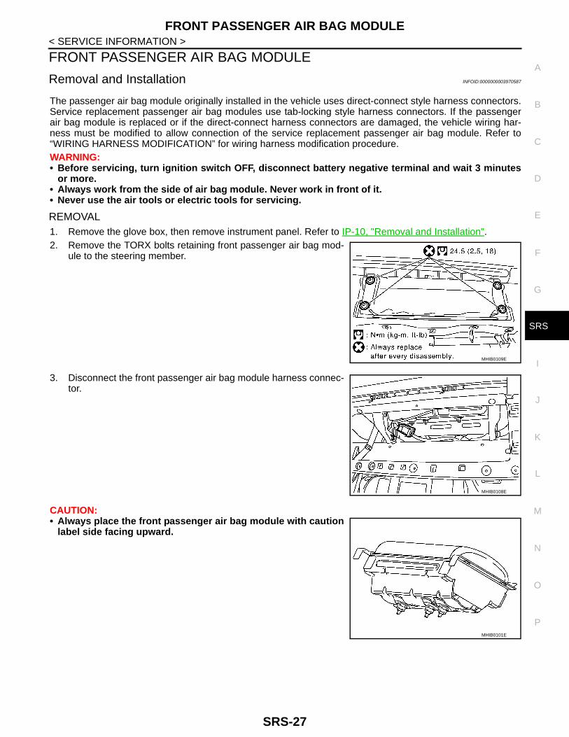
REMOVAL1. Remove the glove box, then remove instrument panel. Refer to IP-10, "Removal and Installation".2. Remove the TORX bolts retaining front passenger air bag mod-
ule to the steering member.
3. Disconnect the front passenger air bag module harness connec-tor.
CAUTION:• Always place the front passenger air bag module with caution
label side facing upward.
MHIB0109E
MHIB0108E
MHIB0101E
SRS-27

FRONT PASSENGER AIR BAG MODULE
< SERVICE INFORMATION >• Never impact the front passenger air bag module.• Replace the front passenger air bag module if it has beendropped or sustained an impact.
• Never attempt to repair or replace damaged direct-connect the front passenger air bag module con-nectors. If a direct-connect harness connector is damaged, the front passenger air bag must bereplaced and the wiring harness modified.
• Never insert any foreign objects (screwdriver, etc.) into the front passenger air bag module or har-ness connectors.
• Never disassemble the front passenger air bag module. • Never expose the front passenger air bag module to temperatures exceeding 90°C (194°F).• Never allow oil, grease, detergent, or water to come in contact with the front passenger air bag mod-
ule.• For removal/installation of the direct-connect SRS connectors, refer to SRS-8, "Direct-Connect SRS
Component Connectors".
INSTALLATION
Original Front Passenger Air Bag ModuleInstall in the reverse order of removal.NOTE:For removal/installation of the direct-connect SRS connectors, refer to SRS-8, "Direct-Connect SRS Compo-nent Connectors".CAUTION:• Never use the old TORX bolt after removal, replace with the new TORX bolt.• If malfunction is detected by the air bag warning lamp, after repair or replacement of the malfunc-
tioning parts, reset the memory using self-diagnosis or CONSULT-III. Refer to SRS-16, "SRS Opera-tion Check".
• After the work is completed, check that no system malfunction is detected by air bag warning lamp.
SERVICE REPLACEMENT FRONT PASSENGER AIR BAG MODULE1. Install the instrument panel. Refer to IP-10, "Removal and Installation".2. Install the front passenger air bag module to the steering mem-
ber.
3. Connect the front passenger air bag module harness connector to yellow 4-pin service replacement airbag connector and fasten connector to mounting bracket.
CAUTION:After the work is completed, perform self-diagnosis to check that no malfunction is detected. Refer toSRS-16, "SRS Operation Check".
WIRING HARNESS MODIFICATIONThe front passenger air bag module originally installed in the vehicle uses direct-connect style harness con-nectors. Service replacement front passenger air bag modules use tab-locking style harness connectors. If the
SBF814E
MHIB0109E
SRS-28

FRONT PASSENGER AIR BAG MODULE
C
D
E
F
G
I
J
K
L
M
A
B
RS
N
O
P
< SERVICE INFORMATION >
S
front passenger air bag module is replaced or if the direct-connect harness connectors are damaged, the vehi-cle wiring harness must be modified to allow connection of the service replacement front passenger air bagmodule.NOTE:The wiring harness modification is to be performed only if the vehicle is equipped with the original front pas-senger air bag module which uses direct-connect harness connectors. If the front passenger air bag module isto be replaced in a vehicle that has already had the service replacement front passenger air bag moduleinstalled, the wiring harness modification is not required.CAUTION:• Never attempt to repair or replace damaged direct-connect front passenger air bag module connec-
tors. If a direct-connect harness connector is damaged, the front passenger air bag module must bereplaced and the wiring harness modified.
• Before servicing, turn ignition switch OFF, disconnect battery negative terminal and wait 3 minutesor more.
• Always work the side of or under front passenger air bag module.• After the work is completed, perform self-diagnosis to check that no malfunction is detected. Refer
to SRS-16, "SRS Operation Check".1. Locate the yellow and orange direct-connect front passenger air bag module harness connectors.2. Use wire cutters to cut back both previously used direct-connect front passenger air bag module harness
connectors from the vehicle wiring harness approximately 50 mm (1.969 in) from the connectors.3. Remove approximately 150 mm (5.906 in) of the vehicle harness covering from the cut end.4. Slide a piece of dual-wall heat shrink tubing (provided in the
front passenger air bag module service kit) onto each wire of thepreviously used vehicle wiring harness.
5. Fold each wire back and insert into the end of the heat shrinktubing so that the end of the wire is approximately centered inthe heat shrink tubing.
6. Use a heat gun to shrink the heat shrink tubing and seal the wire.7. Use electrical tape to secure the modified circuits to the outside of the wiring harness.8. Locate the front passenger air bag module service replacement
connector that is taped back to the main harness. Unwrap thetape to access the yellow service replacement connector andremove the dust cover from the connector.
LHIA0017E
WHIA0062E
MHIB0108E
SRS-29

FRONT SEAT BELT PRE-TENSIONER
< SERVICE INFORMATION >FRONT SEAT BELT PRE-TENSIONER
Removal and Installation INFOID:0000000003970593
For removal and installation procedures, refer to SB-3, "Removal and Installation of Front Seat Belt".
SRS-30

DIAGNOSIS SENSOR UNIT
C
D
E
F
G
I
J
K
L
M
A
B
RS
N
O
P
< SERVICE INFORMATION >
S
DIAGNOSIS SENSOR UNIT
Component Parts Location INFOID:0000000003970594
Removal and Installation INFOID:0000000003970595
WARNING:• Before servicing, turn ignition switch OFF, disconnect battery negative terminal and wait 3 minutes
or more.• Before disconnecting the air bag sensor unit harness connector, be sure to disconnect the each har-
ness connector of the air bag module and pre-tensioner seat belt to prevent air bag deployment bystatic electricity and pre-tensioner seat belt operation.
• Never use the air tools or electric tools for servicing.• When replacing the air bag diagnosis sensor unit, always check with the parts department for the lat-
est parts information. Installing an incorrect air bag diagnosis sensor unit may or may not cause theair bag warning lamp to illuminate and may cause incorrect deployment of the supplemental air bagsand seat belt pre-tensioners in a collision resulting in serious personal injury or death.
REMOVAL1. Always check the air bag diagnosis sensor unit ECU discriminated number (identification number) using
CONSULT-III.2. Disconnect the connectors for each air bag module and seat belt pre-tensioner.3. Remove the center console. Refer to IP-10, "Removal and Installation".4. Disconnect the diagnosis sensor unit harness connectors.5. Remove the TORX bolts from the diagnosis sensor unit.CAUTION:
1. Diagnosis sensor unit harness con-nectors
2. Diagnosis sensor unit
MHIB0163E
SRS-31
DIAGNOSIS SENSOR UNIT
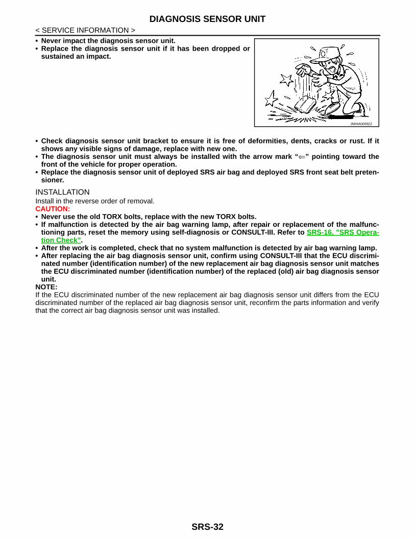
< SERVICE INFORMATION >• Never impact the diagnosis sensor unit.• Replace the diagnosis sensor unit if it has been dropped orsustained an impact.
• Check diagnosis sensor unit bracket to ensure it is free of deformities, dents, cracks or rust. If itshows any visible signs of damage, replace with new one.
• The diagnosis sensor unit must always be installed with the arrow mark “⇐” pointing toward thefront of the vehicle for proper operation.
• Replace the diagnosis sensor unit of deployed SRS air bag and deployed SRS front seat belt preten-sioner.
INSTALLATIONInstall in the reverse order of removal.CAUTION:• Never use the old TORX bolts, replace with the new TORX bolts.• If malfunction is detected by the air bag warning lamp, after repair or replacement of the malfunc-
tioning parts, reset the memory using self-diagnosis or CONSULT-III. Refer to SRS-16, "SRS Opera-tion Check".
• After the work is completed, check that no system malfunction is detected by air bag warning lamp.• After replacing the air bag diagnosis sensor unit, confirm using CONSULT-III that the ECU discrimi-
nated number (identification number) of the new replacement air bag diagnosis sensor unit matchesthe ECU discriminated number (identification number) of the replaced (old) air bag diagnosis sensorunit.
NOTE:If the ECU discriminated number of the new replacement air bag diagnosis sensor unit differs from the ECUdiscriminated number of the replaced air bag diagnosis sensor unit, reconfirm the parts information and verifythat the correct air bag diagnosis sensor unit was installed.
JMHIA0009ZZ
SRS-32

DISPOSAL OF AIR BAG MODULE AND SEAT BELT PRE-TENSIONER
C
D
E
F
G
I
J
K
L
M
A
B
RS
N
O
P
< SERVICE INFORMATION >
S
DISPOSAL OF AIR BAG MODULE AND SEAT BELT PRE-TENSIONER
Caution for Air Bag Module and Seat Belt Pre-tensioner INFOID:0000000003981689
• Before disposing of air bag module, seat belt pre-tensioner, or vehicle equipped with such systems, deploythe systems. If such systems have already been deployed due to an accident, dispose of them as indicatedin checking deployment tool.
• When deploying the air bag module or seat belt pre-tensioner, always use the Special Service Tool Deploy-ment tool [KV99106400].
• When deploying the air bag module or seat belt pre-tensioner, stand at least 5.0 m (16.4 ft) away from thecomponent being deployed.
• When deploying air bag module or seat belt pre-tensioner, a fairly loud noise is made, followed by smokebeing released. The smoke is not poisonous, however, be careful not to inhale smoke since it irritates thethroat and can cause choking.
• Only deploy one air bag module or seat belt pre-tensioner at a time.• Due to heat, leave deployed air bag module unattended for at least 30 minutes after deployment. Leave
deployed seat belt pre-tensioner unattended for at least 10 minutes after deployment.• Always use gloves when handling a deployed air bag module or seat belt pre-tensioner.• Never apply water to the deployed air bag module or seat belt pre-tensioner.• Wash hands thoroughly after finishing work.• Place the vehicle outdoors with an open space of at least 6.0 m (19.7 ft) on all sides when deploying air bag
module or seat belt pre-tensioner while mounted in vehicle.• Use a voltmeter to check that the vehicle battery is fully charged.• Never dispose of the air bag module or seat belt pre-tensioner undeployed.
CHECKING DEPLOYMENT TOOL
Connecting to BatteryCAUTION:The battery must show voltage of 9.6 V or more.Remove the battery from the vehicle and place it on dry wood blocksapproximately 5.0 m (16.4 ft) away from the vehicle.• Wait 3 minutes after the vehicle battery is disconnected before pro-
ceeding.• Connect red clip of deployment tool to battery positive terminal and
black clip to negative terminal.Check that the polarity is correct. The right side lamp in the toolmarked “deployment tool power” should illuminate with a greenlight. If the right side lamp illuminates red, reverse the connec-tions to the battery.
Deployment Tool CheckPlace the deployment tool switch to the ON position. The left sidelamp in the tool, marked “Air Bag Connector Voltage” should illumi-nate. If it does not illuminate, replace the tool.
Air Bag Deployment Tool Lamp Illumination Chart (Battery connected)
PHIA0003E
SBF266H
Switch operationLeft side lamp, green
“AIR BAG CONNECTOR VOLTAGE”Right side lamp, green*
“DEPLOYMENT TOOL POWER”
OFF OFF ON
ON ON ON
SRS-33

DISPOSAL OF AIR BAG MODULE AND SEAT BELT PRE-TENSIONER
< SERVICE INFORMATION >*: If this lamp illuminates red, the tool is connected to the battery incorrectly. Reverse the connections and make sure the lamp illumi-nates green.DEPLOYMENT PROCEDURES FOR AIR BAG MODULE (OUTSIDE OF VEHICLE)• Unless the vehicle is being scrapped, deploying the air bag in the
vehicle is not recommended. This may cause damage to the vehi-cle interior.
• Anchor air bag module bracket in a vise secured to a firm founda-tion during deployment.
Deployment of Driver Air Bag Module (Outside of vehicle)
1. Using wire, secure air bag module to the Tool at 4 places.CAUTION:Use wire of at least 1.0 mm (0.039 in) diameter.
2. Firmly secure Tool with air bag module attached, in a vise.
3. Connect deployment Tool to air bag module connector usingTool C.
4. Connect red clip of Tool to battery positive terminal and blackclip to negative terminal.
5. The lamp on the right side of the tool, marked “deployment toolpower”, must illuminate green, not red.
6. Press the button on the deployment tool. The left side lamp onthe tool, marked “air bag connector voltage”, illuminates and theair bag module deploys.CAUTION:When deploying the driver air bag module, stand at least 5.0 m (16.4 ft) away from the air bag mod-ule.
Deployment of Front Passenger Air Bag Module (Outside of vehicle)
SRS232-E
Tool A : KV99105300
MHIB0103E
Tool C : KV99109700
MHIB0104E
Tool B : KV99106400Tool C : KV99109700
MHIB0105E
SRS-34
DISPOSAL OF AIR BAG MODULE AND SEAT BELT PRE-TENSIONER
C
D
E
F
G
I
J
K
L
M
A
B
RS
N
O
P
< SERVICE INFORMATION >
S
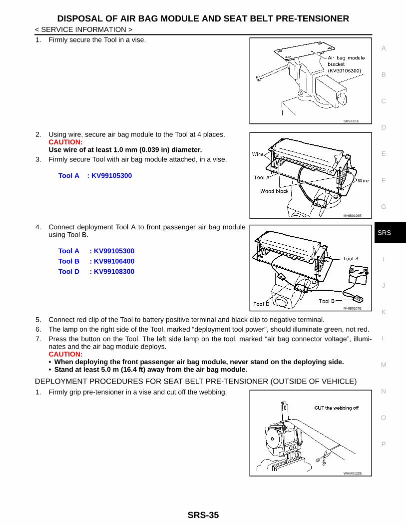
1. Firmly secure the Tool in a vise.
2. Using wire, secure air bag module to the Tool at 4 places.CAUTION:Use wire of at least 1.0 mm (0.039 in) diameter.
3. Firmly secure Tool with air bag module attached, in a vise.
4. Connect deployment Tool A to front passenger air bag moduleusing Tool B.
5. Connect red clip of the Tool to battery positive terminal and black clip to negative terminal.6. The lamp on the right side of the Tool, marked “deployment tool power”, should illuminate green, not red.7. Press the button on the Tool. The left side lamp on the tool, marked “air bag connector voltage”, illumi-
nates and the air bag module deploys.CAUTION:• When deploying the front passenger air bag module, never stand on the deploying side.• Stand at least 5.0 m (16.4 ft) away from the air bag module.
DEPLOYMENT PROCEDURES FOR SEAT BELT PRE-TENSIONER (OUTSIDE OF VEHICLE)1. Firmly grip pre-tensioner in a vise and cut off the webbing.
SRS232-E
Tool A : KV99105300
MHIB0106E
Tool A : KV99105300Tool B : KV99106400 Tool D : KV99108300
MHIB0107E
WHIA0122E
SRS-35
DISPOSAL OF AIR BAG MODULE AND SEAT BELT PRE-TENSIONER
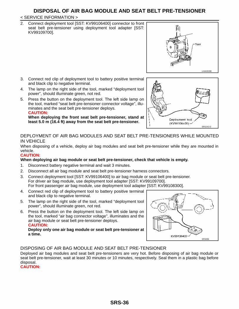
< SERVICE INFORMATION >2. Connect deployment tool [SST: KV99106400] connector to frontseat belt pre-tensioner using deployment tool adapter [SST:KV99109700].
3. Connect red clip of deployment tool to battery positive terminaland black clip to negative terminal.
4. The lamp on the right side of the tool, marked “deployment toolpower”, should illuminate green, not red.
5. Press the button on the deployment tool. The left side lamp onthe tool, marked “seat belt pre-tensioner connector voltage”, illu-minates and the seat belt pre-tensioner deploys.CAUTION:When deploying the front seat belt pre-tensioner, stand atleast 5.0 m (16.4 ft) away from the seat belt pre-tensioner.
DEPLOYMENT OF AIR BAG MODULES AND SEAT BELT PRE-TENSIONERS WHILE MOUNTEDIN VEHICLEWhen disposing of a vehicle, deploy air bag modules and seat belt pre-tensioner while they are mounted invehicle.CAUTION:When deploying air bag module or seat belt pre-tensioner, check that vehicle is empty.1. Disconnect battery negative terminal and wait 3 minutes.2. Disconnect all air bag module and seat belt pre-tensioner harness connectors.3. Connect deployment tool [SST: KV99106400] to air bag module or seat belt pre-tensioner.
For driver air bag module, use deployment tool adapter [SST: KV99109700].For front passenger air bag module, use deployment tool adapter [SST: KV99108300].
4. Connect red clip of deployment tool to battery positive terminaland black clip to negative terminal.
5. The lamp on the right side of the tool, marked “deployment toolpower”, should illuminate green, not red.
6. Press the button on the deployment tool. The left side lamp onthe tool, marked “air bag connector voltage”, illuminates and theair bag module or seat belt pre-tensioner deploys.CAUTION:Deploy only one air bag module or seat belt pre-tensioner ata time.
DISPOSING OF AIR BAG MODULE AND SEAT BELT PRE-TENSIONERDeployed air bag modules and seat belt pre-tensioners are very hot. Before disposing of air bag module orseat belt pre-tensioner, wait at least 30 minutes or 10 minutes, respectively. Seal them in a plastic bag beforedisposal.CAUTION:
LHIA0039E
SRS242-D
SRS006
SRS-36

DISPOSAL OF AIR BAG MODULE AND SEAT BELT PRE-TENSIONER
C
D
E
F
G
I
J
K
L
M
A
B
RS
N
O
P
< SERVICE INFORMATION >
S
• Never apply water to a deployed air bag module or seat beltpre-tensioner.
• Always use gloves when handling a deployed air bag moduleor seat belt pre-tensioner.
• No poisonous gas is produced upon air bag module deploy-ment. However, be careful not to inhale gas since it irritatesthe throat and can cause choking.
• Never disassemble air bag module or seat belt pre-tensioner.• Air bag modules and seat belt pre-tensioners cannot be
reused.• Wash your hands thoroughly after finishing work.
SBF276H
SRS-37
COLLISION DIAGNOSIS
< SERVICE INFORMATION >COLLISION DIAGNOSIS
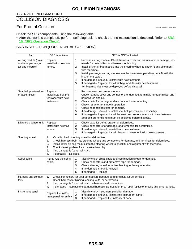
For Frontal Collision INFOID:0000000003981690
Check the SRS components using the following table.• After the work is completed, perform self-diagnosis to check that no malfunction is detected. Refer to SRS-
16, "SRS Operation Check".
SRS INSPECTION (FOR FRONTAL COLLISION)
Part SRS is activated SRS is NOT activated
Air bag module (driver and front passenger air bag module)
ReplaceInstall with new fas-teners.
1. Remove air bag module. Check harness cover and connectors for damage, ter-minals for deformities, and harness for binding.
2. Install driver air bag module into the steering wheel to check fit and alignment with the wheel.
3. Install passenger air bag module into the instrument panel to check fit with the instrument panel.
4. If no damage is found, reinstall with new fasteners.5. If damaged – Replace. Install air bag modules with new fasteners.
Air bag modules must be deployed before disposal.
Seat belt pre-tension-er assemblies
ReplaceInstall seat belt pre-tensioner with new fasteners.
1. Remove seat belt pre-tensioners.Check harness cover and connectors for damage, terminals for deformities, and harness for binding.
2. Check belts for damage and anchors for loose mounting.3. Check retractor for smooth operation.4. Check seat belt adjuster for damage.5. If no damage is found, reinstall seat belt pre-tensioner assembly.6. If damaged – Replace. Install the seat belt pre-tensioners with new fasteners.
Seat belt pre-tensioners must be deployed before disposal.
Diagnosis sensor unit ReplaceInstall with new fas-teners.
1. Check case for dents, cracks, or deformities.2. Check connectors for damage, and terminals for deformities.3. If no damage is found, reinstall with new fasteners.4. If damaged – Replace. Install diagnosis sensor unit with new fasteners.
Steering wheel 1. Visually check steering wheel for deformities.2. Check harness (built into steering wheel) and connectors for damage, and terminals for deformities.3. Install driver air bag module into the steering wheel to check fit and alignment with the wheel.4. Check steering wheel for excessive free play.5. If no damage is found, reinstall.6. If damaged – Replace.
Spiral cable REPLACE the spiral cable.
1. Visually check spiral cable and combination switch for damage.2. Check connectors and protective tape for damage.3. Check steering wheel for noise, binding, or heavy operation.4. If no damage is found, reinstall.5. If damaged – Replace.
Harness and connec-tors
1. Check connectors for poor connection, damage, and terminals for deformities.2. Check harness for binding, chafing, cuts, or deformities.3. If no damage is found, reinstall the harness and connectors.4. If damaged – Replace the damaged harness. Do not attempt to repair, splice or modify any SRS harness.
Instrument panelReplace the instru-ment panel assembly.
1. Visually check instrument panel for damage.2. If no damage is found, reinstall the instrument panel.3. If damaged – Replace the instrument panel.
SRS-38