RESTRAINTS SRC A - PDF.TEXTFILES.COMpdf.textfiles.com/manuals/AUTOMOBILE/NISSAN/EX/2008/SRC.pdf ·...
145
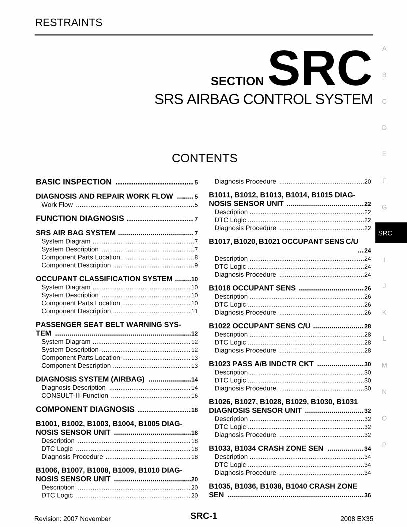
SRC-1 RESTRAINTS C D E F G I J K L M SECTION SRC A B SRC N O P CONTENTS SRS AIRBAG CONTROL SYSTEM BASIC INSPECTION ................................... 5 DIAGNOSIS AND REPAIR WORK FLOW ........ 5 Work Flow ................................................................ 5 FUNCTION DIAGNOSIS .............................. 7 SRS AIR BAG SYSTEM ..................................... 7 System Diagram ....................................................... 7 System Description .................................................. 7 Component Parts Location ....................................... 8 Component Description ............................................ 9 OCCUPANT CLASSIFICATION SYSTEM ........10 System Diagram ..................................................... 10 System Description ................................................ 10 Component Parts Location ..................................... 10 Component Description .......................................... 11 PASSENGER SEAT BELT WARNING SYS- TEM ...................................................................12 System Diagram ..................................................... 12 System Description ................................................ 12 Component Parts Location ..................................... 13 Component Description .......................................... 13 DIAGNOSIS SYSTEM (AIRBAG) .....................14 Diagnosis Description ............................................ 14 CONSULT-III Function ........................................... 16 COMPONENT DIAGNOSIS ........................ 18 B1001, B1002, B1003, B1004, B1005 DIAG- NOSIS SENSOR UNIT ......................................18 Description ............................................................. 18 DTC Logic .............................................................. 18 Diagnosis Procedure .............................................. 18 B1006, B1007, B1008, B1009, B1010 DIAG- NOSIS SENSOR UNIT ......................................20 Description ............................................................. 20 DTC Logic .............................................................. 20 Diagnosis Procedure ..............................................20 B1011, B1012, B1013, B1014, B1015 DIAG- NOSIS SENSOR UNIT ...................................... 22 Description ..............................................................22 DTC Logic ...............................................................22 Diagnosis Procedure ..............................................22 B1017, B1020, B1021 OCCUPANT SENS C/U ... 24 Description ..............................................................24 DTC Logic ...............................................................24 Diagnosis Procedure ..............................................24 B1018 OCCUPANT SENS ................................ 26 Description ..............................................................26 DTC Logic ...............................................................26 Diagnosis Procedure ..............................................26 B1022 OCCUPANT SENS C/U ......................... 28 Description ..............................................................28 DTC Logic ...............................................................28 Diagnosis Procedure ..............................................28 B1023 PASS A/B INDCTR CKT ....................... 30 Description ..............................................................30 DTC Logic ...............................................................30 Diagnosis Procedure ..............................................30 B1026, B1027, B1028, B1029, B1030, B1031 DIAGNOSIS SENSOR UNIT ............................. 32 Description ..............................................................32 DTC Logic ...............................................................32 Diagnosis Procedure ..............................................32 B1033, B1034 CRASH ZONE SEN .................. 34 Description ..............................................................34 DTC Logic ...............................................................34 Diagnosis Procedure ..............................................34 B1035, B1036, B1038, B1040 CRASH ZONE SEN ................................................................... 36 Revision: 2007 November 2008 EX35
-
Upload
dinhkhuong -
Category
Documents
-
view
222 -
download
1
Transcript of RESTRAINTS SRC A - PDF.TEXTFILES.COMpdf.textfiles.com/manuals/AUTOMOBILE/NISSAN/EX/2008/SRC.pdf ·...
RESTRAINTS
C
D
E
SECTION SRCA
B
SRS AIRBAG CONTROL SYSTEM
F
G
I
J
K
L
M
RC
N
O
P
CONTENTS
S
BASIC INSPECTION .................................... 5
DIAGNOSIS AND REPAIR WORK FLOW ......... 5Work Flow .................................................................5
FUNCTION DIAGNOSIS ............................... 7
SRS AIR BAG SYSTEM ...................................... 7System Diagram ........................................................7System Description ...................................................7Component Parts Location ........................................8Component Description .............................................9
OCCUPANT CLASSIFICATION SYSTEM .........10System Diagram ......................................................10System Description .................................................10Component Parts Location ......................................10Component Description ...........................................11
PASSENGER SEAT BELT WARNING SYS-TEM ....................................................................12
System Diagram ......................................................12System Description .................................................12Component Parts Location ......................................13Component Description ...........................................13
DIAGNOSIS SYSTEM (AIRBAG) ......................14Diagnosis Description .............................................14CONSULT-III Function ............................................16
COMPONENT DIAGNOSIS .........................18
B1001, B1002, B1003, B1004, B1005 DIAG-NOSIS SENSOR UNIT .......................................18
Description ..............................................................18DTC Logic ...............................................................18Diagnosis Procedure ...............................................18
B1006, B1007, B1008, B1009, B1010 DIAG-NOSIS SENSOR UNIT .......................................20
Description ..............................................................20DTC Logic ...............................................................20
Diagnosis Procedure ...............................................20
B1011, B1012, B1013, B1014, B1015 DIAG-NOSIS SENSOR UNIT ......................................22
Description ...............................................................22DTC Logic ................................................................22Diagnosis Procedure ...............................................22
B1017, B1020, B1021 OCCUPANT SENS C/U ...24
Description ...............................................................24DTC Logic ................................................................24Diagnosis Procedure ...............................................24
B1018 OCCUPANT SENS ................................26Description ...............................................................26DTC Logic ................................................................26Diagnosis Procedure ...............................................26
B1022 OCCUPANT SENS C/U .........................28Description ...............................................................28DTC Logic ................................................................28Diagnosis Procedure ...............................................28
B1023 PASS A/B INDCTR CKT .......................30Description ...............................................................30DTC Logic ................................................................30Diagnosis Procedure ...............................................30
B1026, B1027, B1028, B1029, B1030, B1031 DIAGNOSIS SENSOR UNIT .............................32
Description ...............................................................32DTC Logic ................................................................32Diagnosis Procedure ...............................................32
B1033, B1034 CRASH ZONE SEN ..................34Description ...............................................................34DTC Logic ................................................................34Diagnosis Procedure ...............................................34
B1035, B1036, B1038, B1040 CRASH ZONE SEN ...................................................................36
SRC-1Revision: 2007 November 2008 EX35
Description .............................................................. 36DTC Logic ............................................................... 36Diagnosis Procedure .............................................. 36
B1042, B1043, B1044, B1045, B1046, B1047 DIAGNOSIS SENSOR UNIT .............................. 38
Description .............................................................. 38DTC Logic ............................................................... 38Diagnosis Procedure .............................................. 38
B1049, B1054 DRIVER AIRBAG MODULE ...... 40Description .............................................................. 40DTC Logic ............................................................... 40Diagnosis Procedure .............................................. 40
B1050, B1055 DRIVER AIRBAG MODULE ...... 42Description .............................................................. 42DTC Logic ............................................................... 42Diagnosis Procedure .............................................. 42
B1051, B1056 DRIVER AIRBAG MODULE ...... 44Description .............................................................. 44DTC Logic ............................................................... 44Diagnosis Procedure .............................................. 44
B1052, B1057 DRIVER AIRBAG MODULE ...... 46Description .............................................................. 46DTC Logic ............................................................... 46Diagnosis Procedure .............................................. 46
B1058, B1059, B1060, B1061, B1062, B1063 DIAGNOSIS SENSOR UNIT .............................. 48
Description .............................................................. 48DTC Logic ............................................................... 48Diagnosis Procedure .............................................. 48
B1065, B1070 ASSIST A/B MODULE .............. 50Description .............................................................. 50DTC Logic ............................................................... 50Diagnosis Procedure .............................................. 50
B1066, B1071 ASSIST A/B MODULE .............. 52Description .............................................................. 52DTC Logic ............................................................... 52Diagnosis Procedure .............................................. 52
B1067, B1072 ASSIST A/B MODULE .............. 54Description .............................................................. 54DTC Logic ............................................................... 54Diagnosis Procedure .............................................. 54
B1068, B1073 ASSIST A/B MODULE .............. 56Description .............................................................. 56DTC Logic ............................................................... 56Diagnosis Procedure .............................................. 56
B1074, B1075, B1076, B1077, B1078, B1079 DIAGNOSIS SENSOR UNIT .............................. 58
Description .............................................................. 58DTC Logic ............................................................... 58Diagnosis Procedure .............................................. 58
B1081 PRE-TEN FRONT RH ............................ 60Description .............................................................. 60DTC Logic ............................................................... 60Diagnosis Procedure ............................................... 60
B1082 PRE-TEN FRONT RH ............................ 62Description .............................................................. 62DTC Logic ............................................................... 62Diagnosis Procedure ............................................... 62
B1083 PRE-TEN FRONT RH ............................ 64Description .............................................................. 64DTC Logic ............................................................... 64Diagnosis Procedure ............................................... 64
B1084 PRE-TEN FRONT RH ............................ 66Description .............................................................. 66DTC Logic ............................................................... 66Diagnosis Procedure ............................................... 66
B1086 PRE-TEN FRONT LH ............................. 68Description .............................................................. 68DTC Logic ............................................................... 68Diagnosis Procedure ............................................... 68
B1087 PRE-TEN FRONT LH ............................. 70Description .............................................................. 70DTC Logic ............................................................... 70Diagnosis Procedure ............................................... 70
B1088 PRE-TEN FRONT LH ............................. 72Description .............................................................. 72DTC Logic ............................................................... 72Diagnosis Procedure ............................................... 72
B1089 PRE-TEN FRONT LH ............................. 74Description .............................................................. 74DTC Logic ............................................................... 74Diagnosis Procedure ............................................... 74
B1106, B1107, B1108, B1109, B1110, B1111 DIAGNOSIS SENSOR UNIT ............................. 76
Description .............................................................. 76DTC Logic ............................................................... 76Diagnosis Procedure ............................................... 76
B1113, B1114 SATELLITE SENS RH .............. 78Description .............................................................. 78DTC Logic ............................................................... 78Diagnosis Procedure ............................................... 78
B1115, B1116 SATELLITE SENS RH .............. 80Description .............................................................. 80DTC Logic ............................................................... 80Diagnosis Procedure ............................................... 80
B1118, B1119 SATELLITE SENS LH ............... 82Description .............................................................. 82DTC Logic ............................................................... 82Diagnosis Procedure ............................................... 82
B1120, B1121 SATELLITE SENS LH ............... 84
SRC-2Revision: 2007 November 2008 EX35

C
D
E
F
G
I
J
K
L
M
A
B
RC
N
O
P
S
Description ..............................................................84DTC Logic ...............................................................84Diagnosis Procedure ...............................................84
B1122, B1123, B1124, B1125, B1126, B1127 DIAGNOSIS SENSOR UNIT ..............................86
Description ..............................................................86DTC Logic ...............................................................86Diagnosis Procedure ...............................................86
B1129 SIDE MODULE RH .................................88Description ..............................................................88DTC Logic ...............................................................88Diagnosis Procedure ...............................................88
B1130 SIDE MODULE RH .................................90Description ..............................................................90DTC Logic ...............................................................90Diagnosis Procedure ...............................................90
B1131 SIDE MODULE RH .................................92Description ..............................................................92DTC Logic ...............................................................92Diagnosis Procedure ...............................................92
B1132 SIDE MODULE RH .................................94Description ..............................................................94DTC Logic ...............................................................94Diagnosis Procedure ...............................................94
B1134 SIDE MODULE LH ..................................96Description ..............................................................96DTC Logic ...............................................................96Diagnosis Procedure ...............................................96
B1135 SIDE MODULE LH ..................................98Description ..............................................................98DTC Logic ...............................................................98Diagnosis Procedure ...............................................98
B1136 SIDE MODULE LH ................................ 100Description ............................................................ 100DTC Logic ............................................................. 100Diagnosis Procedure ............................................. 100
B1137 SIDE MODULE LH ................................ 102Description ............................................................ 102DTC Logic ............................................................. 102Diagnosis Procedure ............................................. 102
B1138, B1139, B1140, B1141, B1142, B1143 DIAGNOSIS SENSOR UNIT ............................ 104
Description ............................................................ 104DTC Logic ............................................................. 104Diagnosis Procedure ............................................. 104
B1145 CURTAIN MODULE RH ....................... 106Description ............................................................ 106DTC Logic ............................................................. 106Diagnosis Procedure ............................................. 106
B1146 CURTAIN MODULE RH ....................... 108
Description .............................................................108DTC Logic ..............................................................108Diagnosis Procedure .............................................108
B1147 CURTAIN MODULE RH ...................... 110Description .............................................................110DTC Logic ..............................................................110Diagnosis Procedure .............................................110
B1148 CURTAIN MODULE RH ...................... 112Description .............................................................112DTC Logic ..............................................................112Diagnosis Procedure .............................................112
B1150 CURTAIN MODULE LH ....................... 114Description .............................................................114DTC Logic ..............................................................114Diagnosis Procedure .............................................114
B1151 CURTAIN MODULE LH ....................... 116Description .............................................................116DTC Logic ..............................................................116Diagnosis Procedure .............................................116
B1152 CURTAIN MODULE LH ....................... 118Description .............................................................118DTC Logic ..............................................................118Diagnosis Procedure .............................................118
B1153 CURTAIN MODULE LH ....................... 120Description .............................................................120DTC Logic ..............................................................120Diagnosis Procedure .............................................120
B1202, B1203, B1204, B1205, B1206, B1207 DIAGNOSIS SENSOR UNIT ........................... 122
Description .............................................................122DTC Logic ..............................................................122Diagnosis Procedure .............................................122
B1209 FRONTAL COLLISION DETECTION .. 124Description .............................................................124DTC Logic ..............................................................124Diagnosis Procedure .............................................124
B1210 SIDE COLLISION DETECTION .......... 126Description .............................................................126DTC Logic ..............................................................126Diagnosis Procedure .............................................126
ECU DIAGNOSIS ....................................... 128
DIAGNOSIS SENSOR UNIT ........................... 128DTC Index .............................................................128Wiring Diagram - SRS AIR BAG CONTROL SYS-TEM - .....................................................................136
SYMPTOM DIAGNOSIS ............................ 142
SRS AIR BAG WARNING LAMP DOES NOT TURN OFF ....................................................... 142
Diagnosis Procedure .............................................142
SRC-3Revision: 2007 November 2008 EX35

SRS AIR BAG WARNING LAMP DOES NOT TURN ON ......................................................... 143
Diagnosis Procedure .............................................143
PASSENGER SEAT BELT WARNING SYS-TEM .................................................................. 144
Diagnosis Procedure .............................................144
PRECAUTION ...........................................145
PRECAUTIONS ................................................145Precaution for Supplemental Restraint System (SRS) "AIR BAG" and "SEAT BELT PRE-TEN-SIONER" ............................................................... 145Service .................................................................. 145Occupant Classification System Precaution ....... 145
SRC-4Revision: 2007 November 2008 EX35

DIAGNOSIS AND REPAIR WORK FLOW
C
D
E
F
G
I
J
K
L
M
A
B
RC
N
O
P
< BASIC INSPECTION >
S
BASIC INSPECTIONDIAGNOSIS AND REPAIR WORK FLOW
Work Flow INFOID:0000000003136139
OVERALL SEQUENCE
DETAILED FLOW
1.GET INFORMATION FOR SYMPTOM
Get the detailed information from the customer about the symptom.
>> GO TO 2.
2.PERFORM PRELIMINARY CHECK
At the beginning of inspection, confirm the condition of power supply circuit, check that the battery is chargedand fuses and fusible links are not blown.Is the inspection result normal?YES >> GO TO 3 or GO TO 4.NO >> Repair or replace the battery and fuse/fusible links.
3.PERFORM SELF-DIAGNOSIS USING “CONSULT-III” (WITH CONSULT-III)
JMHIA0027GB
SRC-5Revision: 2007 November 2008 EX35
DIAGNOSIS AND REPAIR WORK FLOW
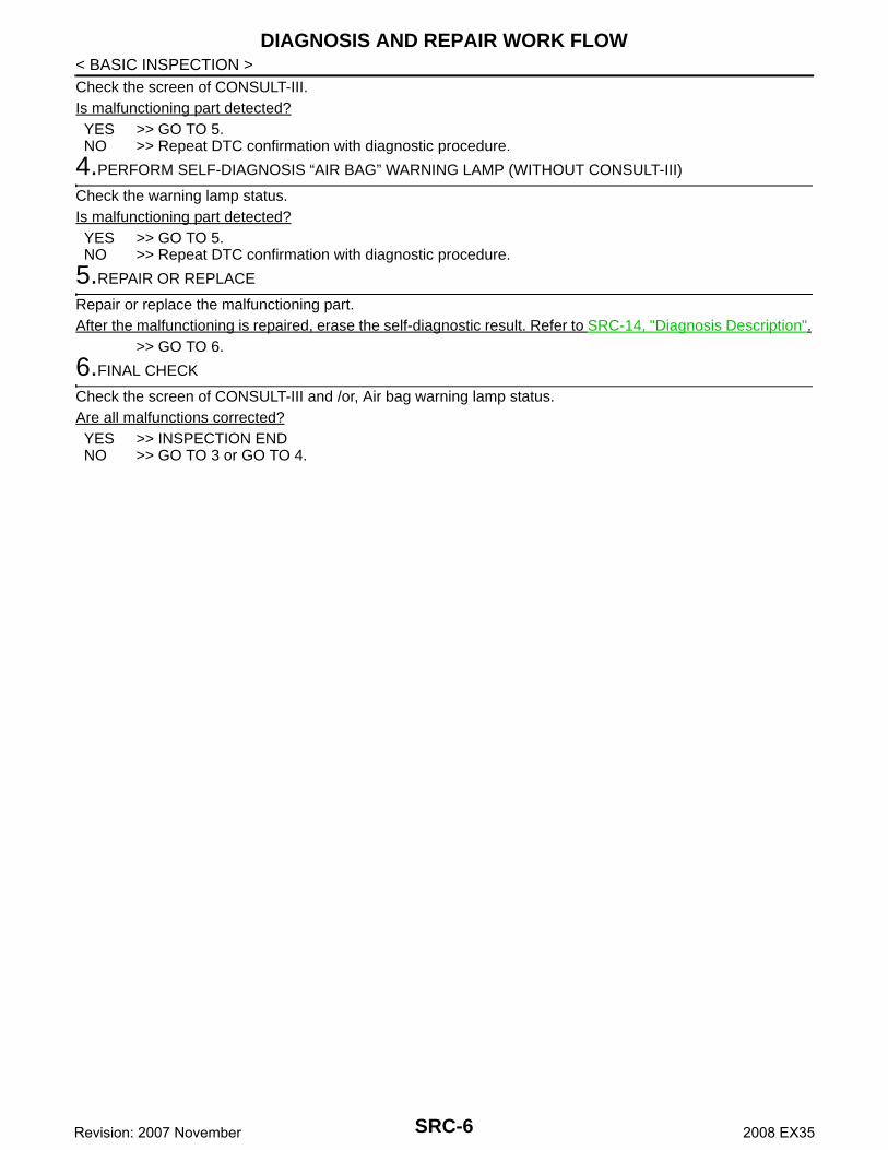
< BASIC INSPECTION >Check the screen of CONSULT-III.Is malfunctioning part detected?YES >> GO TO 5.NO >> Repeat DTC confirmation with diagnostic procedure.4.PERFORM SELF-DIAGNOSIS “AIR BAG” WARNING LAMP (WITHOUT CONSULT-III)
Check the warning lamp status.Is malfunctioning part detected?YES >> GO TO 5.NO >> Repeat DTC confirmation with diagnostic procedure.
5.REPAIR OR REPLACE
Repair or replace the malfunctioning part.After the malfunctioning is repaired, erase the self-diagnostic result. Refer to SRC-14, "Diagnosis Description".
>> GO TO 6.
6.FINAL CHECK
Check the screen of CONSULT-III and /or, Air bag warning lamp status.Are all malfunctions corrected?YES >> INSPECTION ENDNO >> GO TO 3 or GO TO 4.
SRC-6Revision: 2007 November 2008 EX35

SRS AIR BAG SYSTEM
C
D
E
F
G
I
J
K
L
M
A
B
RC
N
O
P
< FUNCTION DIAGNOSIS >
S
FUNCTION DIAGNOSISSRS AIR BAG SYSTEM
System Diagram INFOID:0000000003591502
System Description INFOID:0000000003591503
This SRS Air Bag System has the following function.1. Detects crash and supplies the energy for deploying air bag and seat belt pre-tensioner.2. Detects electrical trouble in SRS Air Bag System and Seat Belt Pre-tensioner System, records trouble
code, and blinking air bag warning lamp.
JMHIA0585GB
SRC-7Revision: 2007 November 2008 EX35
SRS AIR BAG SYSTEM
< FUNCTION DIAGNOSIS >3. Detects and records the deployment of air bag and seat belt pre-tensioner, and turns on air bag warninglamp.4. Indicates malfunctioning portion with blinking times of air bag warning lamp in diagnosis mode.5. Indicate the malfunctioning record by CONSULT-III.6. Suppress the deployment of front passenger air bag when the front passenger seat is empty or when
occupied by turns on front passenger air bag OFF indicator (Cut-off telltale) when passenger seat is occu-pied with a child-seat and child.
7. Turns on seat belt warning lamp when the Occupant Classification System (OCS) option is adult or childand the passenger seat belt buckle switch is not on.
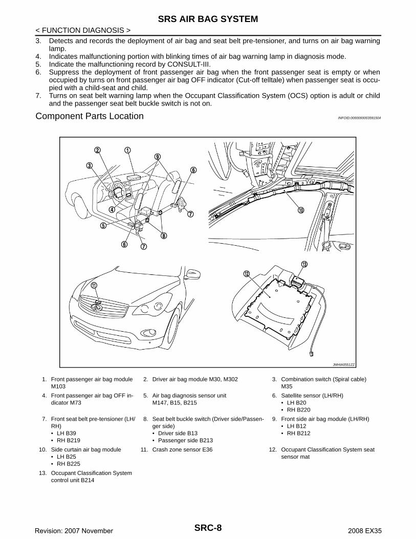
Component Parts Location INFOID:0000000003591504
1. Front passenger air bag module M103
2. Driver air bag module M30, M302 3. Combination switch (Spiral cable) M35
4. Front passenger air bag OFF in-dicator M73
5. Air bag diagnosis sensor unitM147, B15, B215
6. Satellite sensor (LH/RH)• LH B20• RH B220
7. Front seat belt pre-tensioner (LH/RH)• LH B39• RH B219
8. Seat belt buckle switch (Driver side/Passen-ger side)• Driver side B13• Passenger side B213
9. Front side air bag module (LH/RH)• LH B12• RH B212
10. Side curtain air bag module • LH B25• RH B225
11. Crash zone sensor E36 12. Occupant Classification System seat sensor mat
13. Occupant Classification System control unit B214
JMHIA0551ZZ
SRC-8Revision: 2007 November 2008 EX35
SRS AIR BAG SYSTEM
C
D
E
F
G
I
J
K
L
M
A
B
RC
N
O
P
< FUNCTION DIAGNOSIS >
S
Component Description INFOID:0000000003591505
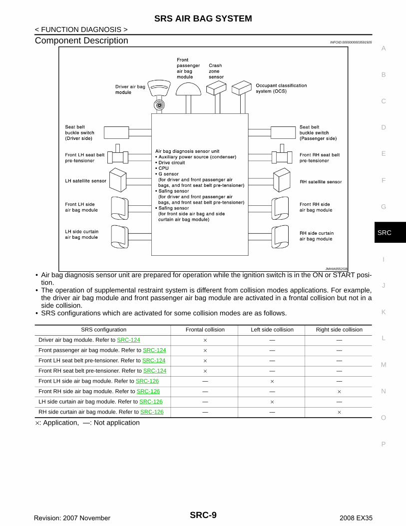
• Air bag diagnosis sensor unit are prepared for operation while the ignition switch is in the ON or START posi-tion.
• The operation of supplemental restraint system is different from collision modes applications. For example,the driver air bag module and front passenger air bag module are activated in a frontal collision but not in aside collision.
• SRS configurations which are activated for some collision modes are as follows.
×: Application, —: Not application
JMHIA0552GB
SRS configuration Frontal collision Left side collision Right side collision
Driver air bag module. Refer to SRC-124 × — —
Front passenger air bag module. Refer to SRC-124 × — —
Front LH seat belt pre-tensioner. Refer to SRC-124 × — —
Front RH seat belt pre-tensioner. Refer to SRC-124 × — —
Front LH side air bag module. Refer to SRC-126 — × —
Front RH side air bag module. Refer to SRC-126 — — ×
LH side curtain air bag module. Refer to SRC-126 — × —
RH side curtain air bag module. Refer to SRC-126 — — ×
SRC-9Revision: 2007 November 2008 EX35

OCCUPANT CLASSIFICATION SYSTEM
< FUNCTION DIAGNOSIS >OCCUPANT CLASSIFICATION SYSTEM
System Diagram INFOID:0000000003591506
OCCUPANT CLASSIFICATION SYSTEM
System Description INFOID:0000000003591507
This Occupant Classification System (OCS) has the following function.1. Suppress the deployment of front passenger air bag when front passenger seat is empty, or when occu-
pied by child and child-seat. Turns on front passenger air bag OFF indicator (Cut-off telltale) when frontpassenger seat is occupied by child-seat and child.
2. Indicates malfunction portion with blinking times of air bag warning lamp in diagnosis mode.3. Indicates the malfunctioning record by CONSULT-III.NOTE:Operation of air bag diagnosis sensor unit when air bag diagnosis sensor unit receives information from Occu-pant Classification System (OCS)
Component Parts Location INFOID:0000000003591508
JMHIA0586GB
Status (front passenger seat)
Passenger air bag Front passenger air bag OFF indicator
(Cut-off telltale)
Air bag warning lamp Seat belt warning lamp (when front passenger seat is unbuckled)
Empty Suppress Off Off Off
Child/ child-seat Suppress On Off On
Adult Enable to deploy Off Off On
Malfunction Suppress On Blinking Off
JMHIA0553ZZ
SRC-10Revision: 2007 November 2008 EX35

OCCUPANT CLASSIFICATION SYSTEM
C
D
E
F
G
I
J
K
L
M
A
B
RC
N
O
P
< FUNCTION DIAGNOSIS >
S
Component Description INFOID:0000000003591509
1. Occupant classification system control unit B214
2. OCS seat sensor mat 3. Passenger air bag OFF indicator M73
A. Occupant classification system control unit harness connector B202, B261
JMHIA0554GB
Component parts Outline of function
OCS seat sensor mat Detects if the passenger seat is empty or occupied
Occupant classification system control unit
Transmits the passenger seat status (occupied or empty) to air bag diagnosis sensor unit
Front passenger air bag OFF indicatorTurns the front passenger air bag OFF indicator lamp ON when the front passenger seat is occupied by a child or a child-seat
SRC-11Revision: 2007 November 2008 EX35

PASSENGER SEAT BELT WARNING SYSTEM
< FUNCTION DIAGNOSIS >PASSENGER SEAT BELT WARNING SYSTEM
System Diagram INFOID:0000000003591510
System Description INFOID:0000000003591511
This Passenger Seat Belt Warning System has the following function.Turns ON seat belt warning lamp, when the Occupant Classification System (OCS) judges adult or child in thefront passenger seat and the passenger seat belt buckle switch is not on.NOTE:In addition, a seat belt warning lamp illuminates and a seat belt alarm sounds, when the driver side seat beltbuckle switch is not on, This does not relate to the air bag diagnosis sensor unit. (Refer to BCM.)NOTE:Operation of air bag diagnosis sensor unit when air bag diagnosis sensor unit receives information from Occu-pant Classification System (OCS)
JMHIA0498GB
Status (front passenger seat)
Passenger air bag Front passenger air bag OFF indicator (Cut-off telltale)
Air bag warning lamp Seat belt warning lamp (When front passenger seat is unbuckled)
Empty Suppress Off Off Off
Child/ child-seat Suppress On Off On
Adult Enable to deploy Off Off On
Malfunction Suppress On Blinking Off
SRC-12Revision: 2007 November 2008 EX35
PASSENGER SEAT BELT WARNING SYSTEM
C
D
E
F
G
I
J
K
L
M
A
B
RC
N
O
P
< FUNCTION DIAGNOSIS >
S
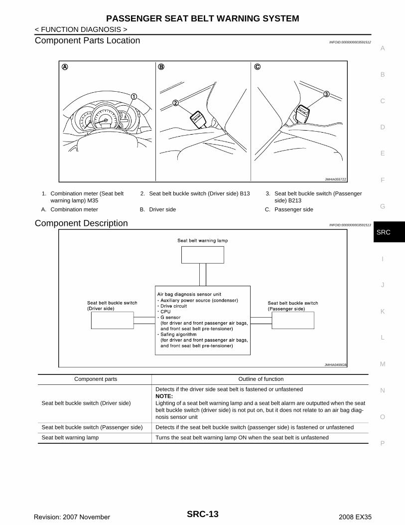
Component Parts Location INFOID:0000000003591512
Component Description INFOID:0000000003591513
1. Combination meter (Seat belt warning lamp) M35
2. Seat belt buckle switch (Driver side) B13 3. Seat belt buckle switch (Passenger side) B213
A. Combination meter B. Driver side C. Passenger side
JMHIA0557ZZ
JMHIA0499GB
Component parts Outline of function
Seat belt buckle switch (Driver side)
Detects if the driver side seat belt is fastened or unfastenedNOTE:Lighting of a seat belt warning lamp and a seat belt alarm are outputted when the seat belt buckle switch (driver side) is not put on, but it does not relate to an air bag diag-nosis sensor unit
Seat belt buckle switch (Passenger side) Detects if the seat belt buckle switch (passenger side) is fastened or unfastened
Seat belt warning lamp Turns the seat belt warning lamp ON when the seat belt is unfastened
SRC-13Revision: 2007 November 2008 EX35
DIAGNOSIS SYSTEM (AIRBAG)
< FUNCTION DIAGNOSIS >DIAGNOSIS SYSTEM (AIRBAG)
Diagnosis Description INFOID:0000000003591514
CAUTION:• Do not use electrical test equipment on any circuit related to the SRS unless instructed in this Ser-
vice Manual. SRS wiring harnesses can be identified by yellow and/or orange harnesses or harnessconnectors.
• Do not repair, splice or modify the SRS wiring harness. If the harness is damaged, replace it with anew one.
• Keep ground portion clean.
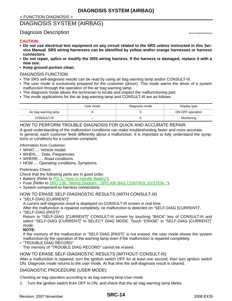
DIAGNOSIS FUNCTION• The SRS self-diagnosis results can be read by using air bag warning lamp and/or CONSULT-III.• The user mode is exclusively prepared for the customer (driver). This mode warns the driver of a system
malfunction through the operation of the air bag warning lamp.• The diagnosis mode allows the technician to locate and inspect the malfunctioning part.• The mode applications for the air bag warning lamp and CONSULT-III are as follows.
HOW TO PERFORM TROUBLE DIAGNOSIS FOR QUICK AND ACCURATE REPAIRA good understanding of the malfunction conditions can make troubleshooting faster and more accurate.In general, each customer feels differently about a malfunction. It is important to fully understand the symp-toms or conditions for a customer complaint.
Information from Customer.• WHAT..... Vehicle model.• WHEN..... Date, Frequencies.• WHERE..... Road conditions.• HOW..... Operating conditions, Symptoms.
Preliminary Check.Check that the following parts are in good order.• Battery (Refer to PG-3, "How to Handle Battery").• Fuse (Refer to SRC-136, "Wiring Diagram - SRS AIR BAG CONTROL SYSTEM -").• System component-to-harness connections.
HOW TO ERASE SELF-DIAGNOSTIC RESULTS (WITH CONSULT-III)• “SELF-DIAG [CURRENT]”
A current self-diagnosis result is displayed on CONSULT-III screen in real time.After the malfunction is repaired completely, no malfunction is detected on “SELF-DIAG [CURRENT]”.
• “SELF-DIAG [PAST]”Return to “SELF-DIAG [CURRENT]” CONSULT-III screen by touching “BACK” key of CONSULT-III andselect “SELF-DIAG [CURRENT]” in SELECT DIAG MODE. Touch “ERASE” in “SELF-DIAG [CURRENT]”mode.NOTE:If the memory of the malfunction in “SELF-DIAG [PAST]” is not erased, the user mode shows the systemmalfunction by the operation of the warning lamp even if the malfunction is repaired completely.
• “TROUBLE DIAG RECORD”The memory of “TROUBLE DIAG RECORD” cannot be erased.
HOW TO ERASE SELF-DIAGNOSTIC RESULTS (WITHOUT CONSULT-III)After a malfunction is repaired, turn the ignition switch OFF for at least one second, then turn ignition switchON. Diagnosis mode returns to the user mode. At that time the self-diagnosis result is cleared.
DIAGNOSTIC PROCEDURE (USER MODE)
Checking air bag operation according to air bag warning lamp-User mode
1. Turn the ignition switch from OFF to ON, and check that the air bag warning lamp blinks.
User mode Diagnosis mode Display type
Air bag warning lamp X X ON-OFF operation
CONSULT-III – X Monitoring
SRC-14Revision: 2007 November 2008 EX35

DIAGNOSIS SYSTEM (AIRBAG)
C
D
E
F
G
I
J
K
L
M
A
B
RC
N
O
P
< FUNCTION DIAGNOSIS >
S
2. Compare the air bag warning lamp blinking pattern with theexamples.
Air bag warning lamp examples (User mode)
BF-1845D
Air bag warning lamp operation -User mode SRS condition Reference item
• No malfunction is detected• No further action is necessary
—
• The system is malfunctioning and needs to be repaired as indicated
Go to SRC-14, "Diagnosis Descrip-tion"
SHIA0011E
SHIA0012E
SRC-15Revision: 2007 November 2008 EX35

DIAGNOSIS SYSTEM (AIRBAG)
< FUNCTION DIAGNOSIS >DIAGNOSTIC PROCEDURE (WITH CONSULT-III)
CONSULT-III Function INFOID:0000000003591515
DIAGNOSIS MODE FOR CONSULT-III• “SELF-DIAG [CURRENT]”
A current self-diagnosis results (also indicated with the number of air bag warning lamp blinks in diagnosismode) are displayed on CONSULT-III screen in real time. This refers to a malfunctioning part requiringrepairs.
• “SELF-DIAG [PAST]”Diagnosis results previously stored in the memory are displayed on CONSULT-III screen. The stored resultsare not erased until memory erasing is executed.
• “TROUBLE DIAG RECORD”With TROUBLE DIAG RECORD, diagnosis results previously erased by a reset operation can be displayedon CONSULT-III screen.
• “DISCRIMINATED NO.”The air bag diagnosis sensor unit for each vehicle model has its own individual classification number. Thisnumber will be displayed on CONSULT-III screen, as shown. When replacing the air bag diagnosis sensorunit, refer to the part number for the compatibility. After installation, replacement with a correct unit can bechecked by confirming this classification number on CONSULT-III screen.After repair, check that the discriminated number of air bag diagnosis sensor unit installed to vehicle are thesame. Refer to SR-16, "Removal and Installation".
HOW TO CHANGE SELF-DIAGNOSIS MODE WITH CONSULT-III
From User Mode to Diagnosis ModeAfter selecting “AIR BAG” on the “SELECT SYSTEM” screen, User mode automatically changes to Diagnosismode.
From Diagnosis Mode to User Mode
• Air bag is deployed• Seat belt pre-tensioner is deployed
Go to SRC-124, "Diagnosis Proce-dure" or SRC-126, "Diagnosis Pro-cedure"
• Air bag diagnosis sensor unit is mal-functioning
• Air bag power supply circuit is mal-functioning
• Air bag warning lamp circuit is mal-functioning
Go to SRC-142, "Diagnosis Proce-dure"
• Air bag diagnosis sensor unit is mal-functioning
• Air bag warning lamp circuit is mal-functioning
Go to SRC-143, "Diagnosis Proce-dure"
Air bag warning lamp operation -User mode SRS condition Reference item
SHIA0013E
SHIA0014E
Diagnostic Mode Description
SELF-DIAG RESULT The self-diagnosis result is displayed (SELF-DIAG [CURRENT], [PAST], [RECORD])
DISCRIMINATED No. Discriminated number of air bag diagnosis sensor unit is displayed
SRC-16Revision: 2007 November 2008 EX35

DIAGNOSIS SYSTEM (AIRBAG)
C
D
E
F
G
I
J
K
L
M
A
B
RC
N
O
P
< FUNCTION DIAGNOSIS >
S
To return to User mode from Diagnosis mode, touch “BACK” key of CONSULT-III until “SELECT SYSTEM”appears, then diagnosis mode automatically changes to User mode.
SELF-DIAGNOSIS FUNCTION (Without CONSULT-III)• The reading of these results is accomplished by “User mode” and “Diagnosis mode”.• After a malfunction is repaired, turn ignition switch ON. Diagnosis mode returns to the user mode. At that
time, the self-diagnosis result is cleared.
HOW TO CHANGE SELF-DIAGNOSIS MODE WITHOUT CONSULT-III
PHIA0709E
SRC-17Revision: 2007 November 2008 EX35
B1001, B1002, B1003, B1004, B1005 DIAGNOSIS SENSOR UNIT
< COMPONENT DIAGNOSIS >COMPONENT DIAGNOSISB1001, B1002, B1003, B1004, B1005 DIAGNOSIS SENSOR UNIT
Description INFOID:0000000003591714
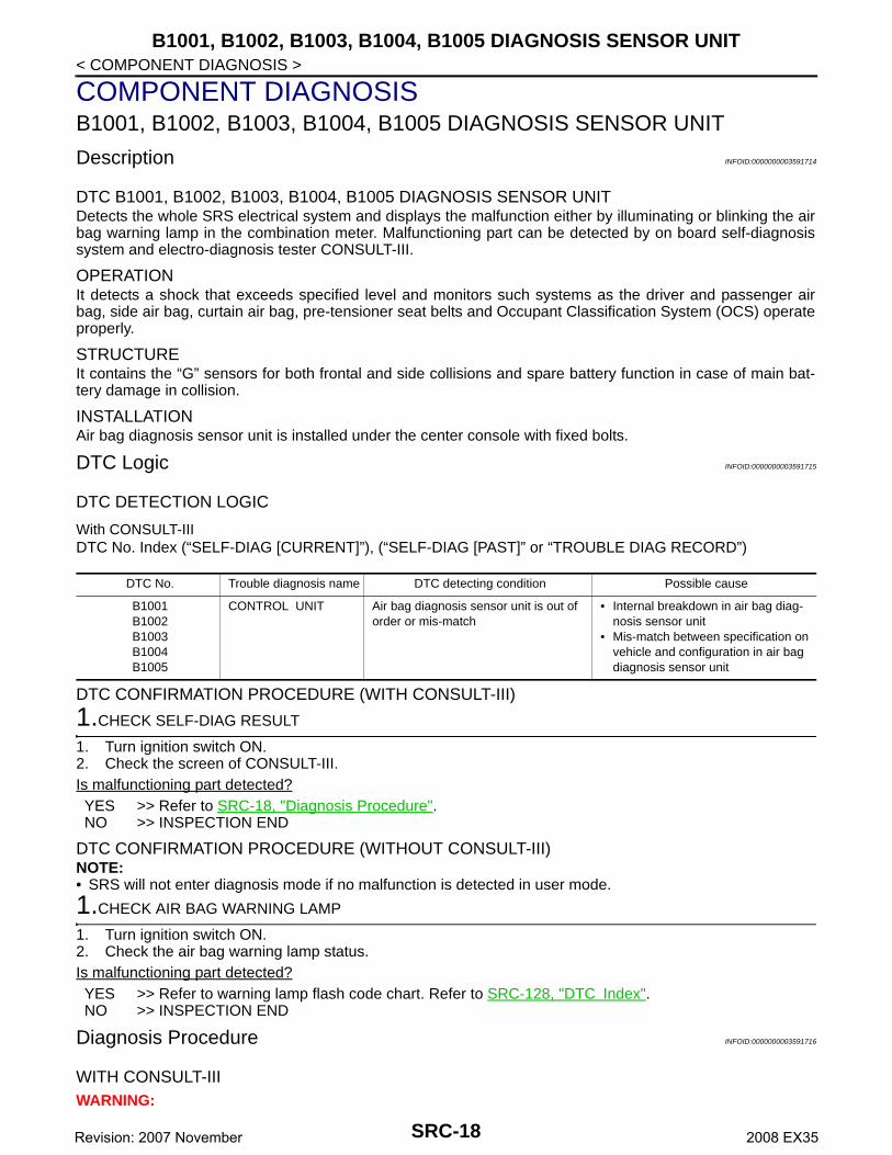
DTC B1001, B1002, B1003, B1004, B1005 DIAGNOSIS SENSOR UNITDetects the whole SRS electrical system and displays the malfunction either by illuminating or blinking the airbag warning lamp in the combination meter. Malfunctioning part can be detected by on board self-diagnosissystem and electro-diagnosis tester CONSULT-III.
OPERATIONIt detects a shock that exceeds specified level and monitors such systems as the driver and passenger airbag, side air bag, curtain air bag, pre-tensioner seat belts and Occupant Classification System (OCS) operateproperly.
STRUCTUREIt contains the “G” sensors for both frontal and side collisions and spare battery function in case of main bat-tery damage in collision.
INSTALLATIONAir bag diagnosis sensor unit is installed under the center console with fixed bolts.
DTC Logic INFOID:0000000003591715
DTC DETECTION LOGIC
With CONSULT-IIIDTC No. Index (“SELF-DIAG [CURRENT]”), (“SELF-DIAG [PAST]” or “TROUBLE DIAG RECORD”)
DTC CONFIRMATION PROCEDURE (WITH CONSULT-III)
1.CHECK SELF-DIAG RESULT
1. Turn ignition switch ON.2. Check the screen of CONSULT-III.Is malfunctioning part detected?YES >> Refer to SRC-18, "Diagnosis Procedure".NO >> INSPECTION END
DTC CONFIRMATION PROCEDURE (WITHOUT CONSULT-III)NOTE:• SRS will not enter diagnosis mode if no malfunction is detected in user mode.
1.CHECK AIR BAG WARNING LAMP
1. Turn ignition switch ON.2. Check the air bag warning lamp status.Is malfunctioning part detected?YES >> Refer to warning lamp flash code chart. Refer to SRC-128, "DTC Index".NO >> INSPECTION END
Diagnosis Procedure INFOID:0000000003591716
WITH CONSULT-IIIWARNING:
DTC No. Trouble diagnosis name DTC detecting condition Possible cause
B1001B1002B1003B1004B1005
CONTROL UNIT Air bag diagnosis sensor unit is out of order or mis-match
• Internal breakdown in air bag diag-nosis sensor unit
• Mis-match between specification on vehicle and configuration in air bag diagnosis sensor unit
SRC-18Revision: 2007 November 2008 EX35
B1001, B1002, B1003, B1004, B1005 DIAGNOSIS SENSOR UNIT
C
D
E
F
G
I
J
K
L
M
A
B
RC
N
O
P
< COMPONENT DIAGNOSIS >
S
• Before servicing, turn ignition switch OFF, disconnect battery negative terminal and wait at least 3minutes. (To discharge backup capacitor.)
• Do not use unspecified tester or other measuring device.
DIAGNOSTIC PROCEDURE
1.CHECK HARNESS CONNECTOR
Check the connection of harness connector.Is the inspection result normal?YES >> GO TO 2.NO >> Replace harness connectors.
2.CHECK WIRING HARNESS
Check the wiring harness externals.Is the inspection result normal?YES >> GO TO 3.NO >> Replace wiring harness.
3.CHECK AIR BAG DIAGNOSIS SENSOR UNIT
1. Replace air bag diagnosis sensor unit. Refer to SR-16, "Exploded View".2. Check “Self diagnostic result” with CONSULT-III.3. Perform DTC confirmation procedure. Refer to SRC-18, "DTC Logic".Is the inspection result normal?YES >> GO TO 1.NO >> INSPECTION END
SRC-19Revision: 2007 November 2008 EX35
B1006, B1007, B1008, B1009, B1010 DIAGNOSIS SENSOR UNIT
< COMPONENT DIAGNOSIS >B1006, B1007, B1008, B1009, B1010 DIAGNOSIS SENSOR UNIT
Description INFOID:0000000003591717
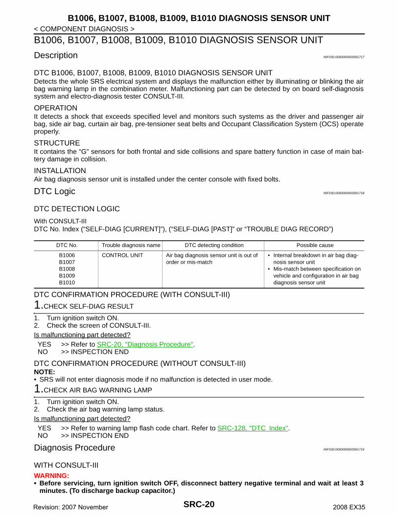
DTC B1006, B1007, B1008, B1009, B1010 DIAGNOSIS SENSOR UNITDetects the whole SRS electrical system and displays the malfunction either by illuminating or blinking the airbag warning lamp in the combination meter. Malfunctioning part can be detected by on board self-diagnosissystem and electro-diagnosis tester CONSULT-III.
OPERATIONIt detects a shock that exceeds specified level and monitors such systems as the driver and passenger airbag, side air bag, curtain air bag, pre-tensioner seat belts and Occupant Classification System (OCS) operateproperly.
STRUCTUREIt contains the “G” sensors for both frontal and side collisions and spare battery function in case of main bat-tery damage in collision.
INSTALLATIONAir bag diagnosis sensor unit is installed under the center console with fixed bolts.
DTC Logic INFOID:0000000003591718
DTC DETECTION LOGIC
With CONSULT-IIIDTC No. Index (“SELF-DIAG [CURRENT]”), (“SELF-DIAG [PAST]” or “TROUBLE DIAG RECORD”)
DTC CONFIRMATION PROCEDURE (WITH CONSULT-III)
1.CHECK SELF-DIAG RESULT
1. Turn ignition switch ON.2. Check the screen of CONSULT-III.Is malfunctioning part detected?YES >> Refer to SRC-20, "Diagnosis Procedure".NO >> INSPECTION END
DTC CONFIRMATION PROCEDURE (WITHOUT CONSULT-III)NOTE:• SRS will not enter diagnosis mode if no malfunction is detected in user mode.
1.CHECK AIR BAG WARNING LAMP
1. Turn ignition switch ON.2. Check the air bag warning lamp status.Is malfunctioning part detected?YES >> Refer to warning lamp flash code chart. Refer to SRC-128, "DTC Index".NO >> INSPECTION END
Diagnosis Procedure INFOID:0000000003591719
WITH CONSULT-IIIWARNING:• Before servicing, turn ignition switch OFF, disconnect battery negative terminal and wait at least 3
minutes. (To discharge backup capacitor.)
DTC No. Trouble diagnosis name DTC detecting condition Possible cause
B1006B1007B1008B1009B1010
CONTROL UNIT Air bag diagnosis sensor unit is out of order or mis-match
• Internal breakdown in air bag diag-nosis sensor unit
• Mis-match between specification on vehicle and configuration in air bag diagnosis sensor unit
SRC-20Revision: 2007 November 2008 EX35
B1006, B1007, B1008, B1009, B1010 DIAGNOSIS SENSOR UNIT
C
D
E
F
G
I
J
K
L
M
A
B
RC
N
O
P
< COMPONENT DIAGNOSIS >
S
• Do not use unspecified tester or other measuring device.
DIAGNOSTIC PROCEDURE
1.CHECK HARNESS CONNECTOR
Check the connection of harness connector.Is the inspection result normal?YES >> GO TO 2.NO >> Replace harness connectors.
2.CHECK WIRING HARNESS
Check the wiring harness externals.Is the inspection result normal?YES >> GO TO 3.NO >> Replace wiring harness.
3.CHECK AIR BAG DIAGNOSIS SENSOR UNIT
1. Replace air bag diagnosis sensor unit. Refer to SR-16, "Exploded View"2. Check “Self diagnostic result” with CONSULT-III.3. Perform DTC confirmation procedure. Refer to SRC-20, "DTC Logic"Is the inspection result normal?YES >> GO TO 1.NO >> INSPECTION END
SRC-21Revision: 2007 November 2008 EX35

B1011, B1012, B1013, B1014, B1015 DIAGNOSIS SENSOR UNIT
< COMPONENT DIAGNOSIS >B1011, B1012, B1013, B1014, B1015 DIAGNOSIS SENSOR UNIT
Description INFOID:0000000003591722
DTC B1011, B1012, B1013, B1014, B1015 DIAGNOSIS SENSOR UNITDetects the whole SRS electrical system and displays the malfunction either by illuminating or blinking the airbag warning lamp in the combination meter. Malfunctioning part can be detected by on board self-diagnosissystem and electro-diagnosis tester CONSULT-III.
OPERATIONIt detects a shock that exceeds specified level and monitors such systems as the driver and passenger airbag, side air bag, curtain air bag, pre-tensioner seat belts and Occupant Classification System (OCS) operateproperly.
STRUCTUREIt contains the “G” sensors for both frontal and side collisions and spare battery function in case of main bat-tery damage in collision.
INSTALLATIONAir bag diagnosis sensor unit is installed under the center console with fixed bolts.
DTC Logic INFOID:0000000003591723
DTC DETECTION LOGIC
With CONSULT-IIIDTC No. Index (“SELF-DIAG [CURRENT]”), (“SELF-DIAG [PAST]” or “TROUBLE DIAG RECORD”)
DTC CONFIRMATION PROCEDURE (WITH CONSULT-III)
1.CHECK SELF-DIAG RESULT
1. Turn ignition switch ON.2. Check the screen of CONSULT-III.Is malfunctioning part detected?YES >> Refer to SRC-22, "Diagnosis Procedure".NO >> INSPECTION END
DTC CONFIRMATION PROCEDURE (WITHOUT CONSULT-III)NOTE:• SRS will not enter diagnosis mode if no malfunction is detected in user mode.
1.CHECK AIR BAG WARNING LAMP
1. Turn ignition switch ON.2. Check the air bag warning lamp status.Is malfunctioning part detected?YES >> Refer to warning lamp flash code chart. Refer to SRC-128, "DTC Index".NO >> INSPECTION END
Diagnosis Procedure INFOID:0000000003591724
WITH CONSULT-IIIWARNING:• Before servicing, turn ignition switch OFF, disconnect battery negative terminal and wait at least 3
minutes. (To discharge backup capacitor.)
DTC No. Trouble diagnosis name DTC detecting condition Possible cause
B1011B1012B1013B1014B1015
CONTROL UNIT Air bag diagnosis sensor unit is out of order or mis-match
• Internal breakdown in air bag diag-nosis sensor unit
• Mis-match between specification on vehicle and configuration in air bag diagnosis sensor unit
SRC-22Revision: 2007 November 2008 EX35

B1011, B1012, B1013, B1014, B1015 DIAGNOSIS SENSOR UNIT
C
D
E
F
G
I
J
K
L
M
A
B
RC
N
O
P
< COMPONENT DIAGNOSIS >
S
• Do not use unspecified tester or other measuring device.
DIAGNOSTIC PROCEDURE
1.CHECK HARNESS CONNECTOR
Check the connection of harness connector.Is the inspection result normal?YES >> GO TO 2.NO >> Replace harness connectors.
2.CHECK WIRING HARNESS
Check the wiring harness externals.Is the inspection result normal?YES >> GO TO 3.NO >> Replace wiring harness.
3.CHECK AIR BAG DIAGNOSIS SENSOR UNIT
1. Replace air bag diagnosis sensor unit. Refer to SR-16, "Exploded View"2. Check “Self diagnostic result” with CONSULT-III.3. Perform DTC confirmation procedure. Refer to SRC-22, "DTC Logic"Is the inspection result normal?YES >> GO TO 1.NO >> INSPECTION END
SRC-23Revision: 2007 November 2008 EX35
B1017, B1020, B1021 OCCUPANT SENS C/U
< COMPONENT DIAGNOSIS >B1017, B1020, B1021 OCCUPANT SENS C/U
Description INFOID:0000000003591727
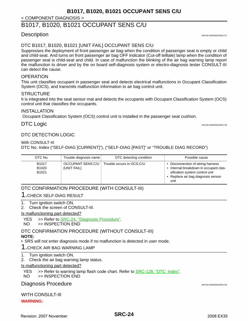
DTC B1017, B1020, B1021 [UNIT FAIL] OCCUPANT SENS C/USuppresses the deployment of front passenger air bag when the condition of passenger seat is empty or childand child-seat. And turns on front passenger air bag OFF indicator (Cut-off telltale) lamp when the condition ofpassenger seat is child-seat and child. In case of malfunction the blinking of the air bag warning lamp reportthe malfunction to driver and by the on board self-diagnosis system or electro-diagnosis tester CONSULT-IIIcan detect the cause.
OPERATIONThis unit classifies occupant in passenger seat and detects electrical malfunctions in Occupant ClassificationSystem (OCS), and transmits malfunction information to air bag control unit.
STRUCTUREIt is integrated into the seat sensor mat and detects the occupants with Occupant Classification System (OCS)control unit that classifies the occupants.
INSTALLATION Occupant Classification System (OCS) control unit is installed in the passenger seat cushion.
DTC Logic INFOID:0000000003591728
DTC DETECTION LOGIC
With CONSULT-IIIDTC No. Index (“SELF-DIAG [CURRENT]”), (“SELF-DIAG [PAST]” or “TROUBLE DIAG RECORD”)
DTC CONFIRMATION PROCEDURE (WITH CONSULT-III)
1.CHECK SELF-DIAG RESULT
1. Turn ignition switch ON.2. Check the screen of CONSULT-III.Is malfunctioning part detected?YES >> Refer to SRC-24, "Diagnosis Procedure".NO >> INSPECTION END
DTC CONFIRMATION PROCEDURE (WITHOUT CONSULT-III)NOTE:• SRS will not enter diagnosis mode if no malfunction is detected in user mode.
1.CHECK AIR BAG WARNING LAMP
1. Turn ignition switch ON.2. Check the air bag warning lamp status.Is malfunctioning part detected?YES >> Refer to warning lamp flash code chart. Refer to SRC-128, "DTC Index".NO >> INSPECTION END
Diagnosis Procedure INFOID:0000000003591729
WITH CONSULT-IIIWARNING:
DTC No. Trouble diagnosis name DTC detecting condition Possible cause
B1017B1020B1021
OCCUPANT SENS C/U [UNIT FAIL]
Trouble occurs in OCS-C/U • Disconnection of wiring harness• Internal breakdown in occupant clas-
sification system control unit• Replace air bag diagnosis sensor
unit
SRC-24Revision: 2007 November 2008 EX35

B1017, B1020, B1021 OCCUPANT SENS C/U
C
D
E
F
G
I
J
K
L
M
A
B
RC
N
O
P
< COMPONENT DIAGNOSIS >
S
• Before servicing, turn ignition switch OFF, disconnect battery negative terminal and wait at least 3minutes. (To discharge backup capacitor.)
• Do not use unspecified tester or other measuring device.
DIAGNOSTIC PROCEDURE
1.CHECK HARNESS CONNECTOR
Check the connection of harness connector.Is the inspection result normal?YES >> GO TO 2.NO >> Replace harness connectors.
2.CHECK WIRING HARNESS
Check the wiring harness externals.Is the inspection result normal?YES >> GO TO 3.NO >> Replace wiring harness.
3.CHECK OCCUPANT CLASSIFICATION SYSTEM CONTROL UNIT
1. Replace occupant classification system control unit. (front passenger side seat cushion assembly.) Referto SE-87, "Exploded View"
2. Check “Self diagnostic result” with CONSULT-III.3. Perform DTC confirmation procedure. Refer to SRC-24, "DTC Logic"Is DTC detected?YES >> GO TO 4.NO >> INSPECTION END
4.CHECK AIR BAG DIAGNOSIS SENSOR UNIT
1. Replace air bag diagnosis sensor unit. Refer to SR-16, "Removal and Installation"2. Check “Self diagnostic result” with CONSULT-III.3. Perform DTC confirmation procedure. Refer to SRC-24, "DTC Logic"Is DTC detected?YES >> GO TO 1.NO >> INSPECTION END
SRC-25Revision: 2007 November 2008 EX35

B1018 OCCUPANT SENS
< COMPONENT DIAGNOSIS >B1018 OCCUPANT SENS
Description INFOID:0000000003591730
DTC B1018 [UNIT FAIL] OCCUPANT SENSSuppresses the deployment of front passenger air bag when the condition of passenger seat is empty or childand child-seat. And turns on front passenger air bag OFF indicator (Cut-off telltale) lamp when the condition ofpassenger seat is child-seat and child. In case of malfunction the blinking of the air bag warning lamp reportsthe malfunction to driver and by the on board self-diagnosis system or electro-diagnosis tester CONSULT-IIIcan detect the cause.
OPERATIONThe unit classifies occupant in passenger seat and transmits it to Occupant Classification System (OCS) con-trol unit.
STRUCTUREPlural sensors are installed in the sensor mat to prevent incorrect sensing induced by the sitting position.
INSTALLATIONSeat sensor mat is installed in the passenger seat cushion.
DTC Logic INFOID:0000000003591731
DTC DETECTION LOGIC
With CONSULT-IIIDTC No. Index (“SELF-DIAG [CURRENT]”), (“SELF-DIAG [PAST]” or “TROUBLE DIAG RECORD”)
DTC CONFIRMATION PROCEDURE (WITH CONSULT-III)
1.CHECK SELF-DIAG RESULT
1. Turn ignition switch ON.2. Check the screen of CONSULT-III.Is malfunctioning part detected?YES >> Refer to SRC-26, "Diagnosis Procedure".NO >> INSPECTION END
DTC CONFIRMATION PROCEDURE (WITHOUT CONSULT-III)NOTE:• SRS will not enter diagnosis mode if no malfunction is detected in user mode.
1.CHECK AIR BAG WARNING LAMP
1. Turn ignition switch ON.2. Check the air bag warning lamp status.Is malfunctioning part detected?YES >> Refer to warning lamp flash code chart. Refer to SRC-128, "DTC Index".NO >> INSPECTION END
Diagnosis Procedure INFOID:0000000003591732
WITH CONSULT-IIIWARNING:• Before servicing, turn ignition switch OFF, disconnect battery negative terminal and wait at least 3
minutes. (To discharge backup capacitor.)• Do not use unspecified tester or other measuring device.
DTC No. Trouble diagnosis name DTC detecting condition Possible cause
B1018 OCCUPANT SENS [UNIT FAIL]
Trouble occurs in OCS-SENSOR • Disconnection of wiring harness• Internal breakdown in occupant clas-
sification system sensor
SRC-26Revision: 2007 November 2008 EX35

B1018 OCCUPANT SENS
C
D
E
F
G
I
J
K
L
M
A
B
RC
N
O
P
< COMPONENT DIAGNOSIS >
S
DIAGNOSTIC PROCEDURE
1.CHECK HARNESS CONNECTOR
Check the connection of harness connector.Is the inspection result normal?YES >> GO TO 2.NO >> Replace harness connectors.
2.CHECK WIRING HARNESS
Check the wiring harness externals.Is the inspection result normal?YES >> GO TO 3.NO >> Replace wiring harness.
3.CHECK OCCUPANT CLASSIFICATION SYSTEM SENSOR
1. Replace occupant classification system sensor. (front passenger side seat cushion assembly.) RefertoSE-87, "Exploded View".
2. Check “Self diagnostic result” with CONSULT-III.3. Perform DTC confirmation procedure. Refer to SRC-26, "DTC Logic".Is DTC detected?YES >> GO TO 1.NO >> INSPECTION END
SRC-27Revision: 2007 November 2008 EX35
B1022 OCCUPANT SENS C/U
< COMPONENT DIAGNOSIS >B1022 OCCUPANT SENS C/U
Description INFOID:0000000003591734
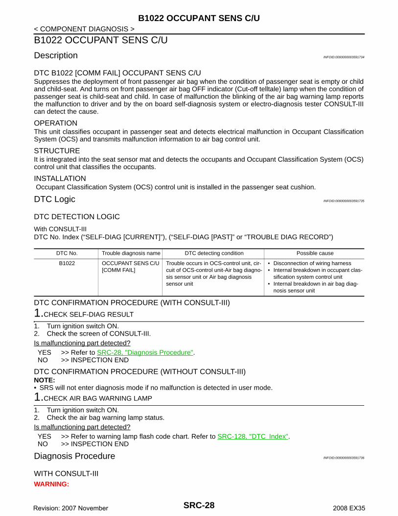
DTC B1022 [COMM FAIL] OCCUPANT SENS C/USuppresses the deployment of front passenger air bag when the condition of passenger seat is empty or childand child-seat. And turns on front passenger air bag OFF indicator (Cut-off telltale) lamp when the condition ofpassenger seat is child-seat and child. In case of malfunction the blinking of the air bag warning lamp reportsthe malfunction to driver and by the on board self-diagnosis system or electro-diagnosis tester CONSULT-IIIcan detect the cause.
OPERATIONThis unit classifies occupant in passenger seat and detects electrical malfunction in Occupant ClassificationSystem (OCS) and transmits malfunction information to air bag control unit.
STRUCTUREIt is integrated into the seat sensor mat and detects the occupants and Occupant Classification System (OCS)control unit that classifies the occupants.
INSTALLATION Occupant Classification System (OCS) control unit is installed in the passenger seat cushion.
DTC Logic INFOID:0000000003591735
DTC DETECTION LOGIC
With CONSULT-IIIDTC No. Index (“SELF-DIAG [CURRENT]”), (“SELF-DIAG [PAST]” or “TROUBLE DIAG RECORD”)
DTC CONFIRMATION PROCEDURE (WITH CONSULT-III)
1.CHECK SELF-DIAG RESULT
1. Turn ignition switch ON.2. Check the screen of CONSULT-III.Is malfunctioning part detected?YES >> Refer to SRC-28, "Diagnosis Procedure".NO >> INSPECTION END
DTC CONFIRMATION PROCEDURE (WITHOUT CONSULT-III)NOTE:• SRS will not enter diagnosis mode if no malfunction is detected in user mode.
1.CHECK AIR BAG WARNING LAMP
1. Turn ignition switch ON.2. Check the air bag warning lamp status.Is malfunctioning part detected?YES >> Refer to warning lamp flash code chart. Refer to SRC-128, "DTC Index".NO >> INSPECTION END
Diagnosis Procedure INFOID:0000000003591736
WITH CONSULT-IIIWARNING:
DTC No. Trouble diagnosis name DTC detecting condition Possible cause
B1022 OCCUPANT SENS C/U [COMM FAIL]
Trouble occurs in OCS-control unit, cir-cuit of OCS-control unit-Air bag diagno-sis sensor unit or Air bag diagnosis sensor unit
• Disconnection of wiring harness• Internal breakdown in occupant clas-
sification system control unit• Internal breakdown in air bag diag-
nosis sensor unit
SRC-28Revision: 2007 November 2008 EX35

B1022 OCCUPANT SENS C/U
C
D
E
F
G
I
J
K
L
M
A
B
RC
N
O
P
< COMPONENT DIAGNOSIS >
S
• Before servicing, turn ignition switch OFF, disconnect battery negative terminal and wait at least 3minutes. (To discharge backup capacitor.)
• Do not use unspecified tester or other measuring device.
DIAGNOSTIC PROCEDURE
1.CHECK HARNESS CONNECTOR
Check the connection of harness connector.Is the inspection result normal?YES >> GO TO 2.NO >> Replace harness connectors.
2.CHECK WIRING HARNESS
Check the wiring harness externals.Is the inspection result normal?YES >> GO TO 3.NO >> Replace wiring harness.
3.CHECK OCCUPANT CLASSIFICATION SYSTEM SENSOR
1. Replace occupant classification system sensor. (front passenger side seat cushion assembly.) Refer toSE-87, "Exploded View".
2. Check “Self diagnostic result” with CONSULT-III.3. Perform DTC confirmation procedure. Refer to SRC-28, "DTC Logic".Is DTC detected?YES >> GO TO 4.NO >> INSPECTION END
4.CHECK AIR BAG DIAGNOSIS SENSOR UNIT
1. Replace air bag diagnosis sensor unit. Refer to SR-16, "Exploded View".2. Check “Self diagnostic result” with CONSULT-III.3. Perform DTC confirmation procedure. Refer to SRC-28, "DTC Logic".Is DTC detected?YES >> GO TO 1.NO >> INSPECTION END
SRC-29Revision: 2007 November 2008 EX35

B1023 PASS A/B INDCTR CKT
< COMPONENT DIAGNOSIS >B1023 PASS A/B INDCTR CKT
Description INFOID:0000000003591737
DTC B1023 PASS A/B INDCTR CKTSuppresses the deployment of front passenger air bag when the condition of passenger seat is empty or childand child-seat. And turns on front passenger air bag OFF indicator (Cut-off telltale) lamp when the condition ofpassenger seat is child-seat and child. In case of malfunction the blinking of the air bag warning lamp reportsthe malfunction to driver and by the on board self-diagnosis system or electro-diagnosis tester CONSULT-IIIcan detect the cause.
OPERATIONTurns on front passenger air bag OFF indicator (Cut-off telltale) when the passenger seat is empty or occupiedby child-seat and child.
STRUCTUREFront passenger air bag OFF indicator (Cut-off telltale) with LED illumination.
INSTALLATIONFront passenger air bag OFF indicator (Cut-off telltale) is installed at the instrument panel center.
DTC Logic INFOID:0000000003591738
DTC DETECTION LOGIC
With CONSULT-IIIDTC No. Index (“SELF-DIAG [CURRENT]”), (“SELF-DIAG [PAST]” or “TROUBLE DIAG RECORD”)
DTC CONFIRMATION PROCEDURE (WITH CONSULT-III)
1.CHECK SELF-DIAG RESULT
1. Turn ignition switch ON.2. Check the screen of CONSULT-III.Is malfunctioning part detected?YES >> Refer to SRC-30, "Diagnosis Procedure".NO >> INSPECTION END
DTC CONFIRMATION PROCEDURE (WITHOUT CONSULT-III)NOTE:• SRS will not enter diagnosis mode if no malfunction is detected in user mode.
1.CHECK AIR BAG WARNING LAMP
1. Turn ignition switch ON.2. Check the air bag warning lamp status.Is malfunctioning part detected?YES >> Refer to warning lamp flash code chart. Refer to SRC-128, "DTC Index".NO >> INSPECTION END
Diagnosis Procedure INFOID:0000000003591739
WITH CONSULT-IIIWARNING:• Before servicing, turn ignition switch OFF, disconnect battery negative terminal and wait at least 3
minutes. (To discharge backup capacitor.)
DTC No. Trouble diagnosis name DTC detecting condition Possible cause
B1023 PASS A/B INDCTR CKT [UNIT FAIL]
Cut-off telltale circuit is open or shorted to ground or the circuits are shorted each other
• Disconnection of wiring harness• Internal breakdown in front passen-
ger air bag OFF indicator• Internal breakdown in air bag diag-
nosis sensor unit
SRC-30Revision: 2007 November 2008 EX35

B1023 PASS A/B INDCTR CKT
C
D
E
F
G
I
J
K
L
M
A
B
RC
N
O
P
< COMPONENT DIAGNOSIS >
S
• Do not use unspecified tester or other measuring device.
DIAGNOSTIC PROCEDURE
1.CHECK HARNESS CONNECTOR
Check the connection of harness connector.Is the inspection result normal?YES >> GO TO 2.NO >> Replace harness connectors.
2.CHECK WIRING HARNESS
Check the wiring harness externals.Is the inspection result normal?YES >> GO TO 3.NO >> Replace wiring harness.
3.CHECK PASSENGER AIR BAG OFF INDICATOR
1. Replace front passenger air bag OFF indicator (Cut-off telltale). Refer to IP-11, "Exploded View"2. Check “Self diagnostic result” with CONSULT-III.3. Perform DTC confirmation procedure. Refer to SRC-30, "DTC Logic".Is DTC detected?YES >> GO TO 4.NO >> INSPECTION END
4.CHECK AIR BAG DIAGNOSIS SENSOR UNIT
1. Replace air bag diagnosis sensor unit. Refer to SR-16, "Exploded View".2. Check “Self diagnostic result” with CONSULT-III.3. Perform DTC confirmation procedure. Refer to SRC-30, "DTC Logic".Is DTC detected?YES >> GO TO 1.NO >> INSPECTION END
SRC-31Revision: 2007 November 2008 EX35

B1026, B1027, B1028, B1029, B1030, B1031 DIAGNOSIS SENSOR UNIT
< COMPONENT DIAGNOSIS >B1026, B1027, B1028, B1029, B1030, B1031 DIAGNOSIS SENSOR UNIT
Description INFOID:0000000003591741
DTC B1026, B1027, B1028, B1029, B1030, B1031 DIAGNOSIS SENSOR UNITDetects the whole SRS electrical system and displays the malfunction either by illuminating or blinking the airbag warning lamp in the combination meter. Malfunctioning part can be detected by on board self-diagnosissystem and electro-diagnosis tester CONSULT-III.
OPERATIONIt detects a shock that exceeds specified level and monitors such systems as the driver and passenger airbag, side air bag, curtain air bag, pre-tensioner seat belts and Occupant Classification System (OCS) operateproperly.
STRUCTUREIt contains the “G” sensors for both frontal and side collisions and spare battery function in case of main bat-tery damage in collision.
INSTALLATIONAir bag diagnosis sensor unit is installed under the center console with fixed bolts.
DTC Logic INFOID:0000000003591742
DTC DETECTION LOGIC
With CONSULT-IIIDTC No. Index (“SELF-DIAG [CURRENT]”), (“SELF-DIAG [PAST]” or “TROUBLE DIAG RECORD”)
DTC CONFIRMATION PROCEDURE (WITH CONSULT-III)
1.CHECK SELF-DIAG RESULT
1. Turn ignition switch ON.2. Check the screen of CONSULT-III.Is malfunctioning part detected?YES >> Refer to SRC-32, "Diagnosis Procedure".NO >> INSPECTION END
DTC CONFIRMATION PROCEDURE (WITHOUT CONSULT-III)NOTE:• SRS will not enter diagnosis mode if no malfunction is detected in user mode.
1.CHECK AIR BAG WARNING LAMP
1. Turn ignition switch ON.2. Check the air bag warning lamp status.Is malfunctioning part detected?YES >> Refer to warning lamp flash code chart. Refer to SRC-128, "DTC Index".NO >> INSPECTION END
Diagnosis Procedure INFOID:0000000003591743
WITH CONSULT-IIIWARNING:
DTC No. Trouble diagnosis name DTC detecting condition Possible cause
B1026B1027B1028B1029B1030B1031
CONTROL UNIT Air bag diagnosis sensor unit is out of order or mis-match
• Internal breakdown in air bag diag-nosis sensor unit
• Mis-match between specification on vehicle and configuration in air bag diagnosis sensor unit
SRC-32Revision: 2007 November 2008 EX35

B1026, B1027, B1028, B1029, B1030, B1031 DIAGNOSIS SENSOR UNIT
C
D
E
F
G
I
J
K
L
M
A
B
RC
N
O
P
< COMPONENT DIAGNOSIS >
S
• Before servicing, turn ignition switch OFF, disconnect battery negative terminal and wait at least 3minutes. (To discharge backup capacitor.)
• Do not use unspecified tester or other measuring device.
DIAGNOSTIC PROCEDURE
1.CHECK HARNESS CONNECTOR
Check the connection of harness connector.Is the inspection result normal?YES >> GO TO 2.NO >> Replace harness connectors.
2.CHECK WIRING HARNESS
Check the wiring harness externals.Is the inspection result normal?YES >> GO TO 3.NO >> Replace wiring harness.
3.CHECK AIR BAG DIAGNOSIS SENSOR UNIT
1. Replace air bag diagnosis sensor unit. Refer to SR-16, "Exploded View".2. Check “Self diagnostic result” with CONSULT-III.3. Perform DTC confirmation procedure. Refer to SRC-32, "DTC Logic".Is DTC detected?YES >> GO TO 1.NO >> INSPECTION END
SRC-33Revision: 2007 November 2008 EX35

B1033, B1034 CRASH ZONE SEN
< COMPONENT DIAGNOSIS >B1033, B1034 CRASH ZONE SEN
Description INFOID:0000000003591757
DTC B1033, B1034 [UNIT FAIL] CRASH ZONE SENSORMain “G” sensor generates signal voltage, when it detects deceleration beyond the specified level caused byvehicle frontal collision.
OPERATIONWhen air bag diagnosis sensor unit define the both signal voltage of the “G” sensor and the safing algorithm tobe that of collision which exceeds specified level, the driving circuit switches on and feeds the electric ignitor ofboth driver and passenger air bags and pre-tensioner seat belt.
STRUCTUREIntegrated type of the “G” sensor element for frontal collision with output terminals for signal voltage.
INSTALLATIONCrash zone sensor is installed on the radiator core support assembly with fixed nuts.
DTC Logic INFOID:0000000003591758
DTC DETECTION LOGIC
With CONSULT-IIIDTC No. Index (“SELF-DIAG [CURRENT]”), (“SELF-DIAG [PAST]” or “TROUBLE DIAG RECORD)
DTC CONFIRMATION PROCEDURE (WITH CONSULT-III)
1.CHECK SELF-DIAG RESULT
1. Turn ignition switch ON.2. Check the screen of CONSULT-III.Is malfunctioning part detected?YES >> Refer to SRC-34, "Diagnosis Procedure".NO >> INSPECTION END
DTC CONFIRMATION PROCEDURE (WITHOUT CONSULT-III)NOTE:• SRS will not enter diagnosis mode if no malfunction is detected in user mode.
1.CHECK AIR BAG WARNING LAMP-
1. Turn ignition switch ON.2. Check the air bag warning lamp status.Is malfunctioning part detected?YES >> Refer to warning lamp flash code chart. Refer to SRC-128, "DTC Index".NO >> INSPECTION END
Diagnosis Procedure INFOID:0000000003591759
WITH CONSULT-IIIWARNING:• Before servicing, turn ignition switch OFF, disconnect battery negative terminal and wait at least 3
minutes. (To discharge backup capacitor.)• Do not use unspecified tester or other measuring device.
DTC No. Trouble diagnosis name DTC detecting condition Possible cause
B1033B1034
CRASH ZONE SEN-SOR [UNIT FAIL]
Crash zone sensor is out of order • Disconnection of wiring harness• Internal breakdown in crash zone
sensor• Internal breakdown in air bag diag-
nosis sensor unit
SRC-34Revision: 2007 November 2008 EX35

B1033, B1034 CRASH ZONE SEN
C
D
E
F
G
I
J
K
L
M
A
B
RC
N
O
P
< COMPONENT DIAGNOSIS >
S
DIAGNOSTIC PROCEDURE
1.CHECK HARNESS CONNECTOR
Check the connection of harness connector.Is the inspection result normal?YES >> GO TO 2.NO >> Replace harness connectors.
2.CHECK WIRING HARNESS
Check the wiring harness externals.Is the inspection result normal?YES >> GO TO 3.NO >> Replace wiring harness.
3.CHECK CRASH ZONE SENSOR
1. Replace crash zone sensor. Refer to SR-12, "Exploded View".2. Check “Self diagnostic result” with CONSULT-III.3. Perform DTC confirmation procedure. Refer to SRC-34, "DTC Logic".Is DTC detected?YES >> GO TO 4.NO >> INSPECTION END
4.CHECK AIR BAG DIAGNOSIS SENSOR UNIT
1. Replace air bag diagnosis sensor unit. Refer to SR-16, "Exploded View".2. Check “Self diagnostic result” with CONSULT-III.3. Perform DTC confirmation procedure. Refer to SRC-34, "DTC Logic".Is DTC detected?YES >> GO TO 1.NO >> INSPECTION END
SRC-35Revision: 2007 November 2008 EX35

B1035, B1036, B1038, B1040 CRASH ZONE SEN
< COMPONENT DIAGNOSIS >B1035, B1036, B1038, B1040 CRASH ZONE SEN
Description INFOID:0000000003591760
DTC B1035, B1036, B1038, B1040 [COMM FAIL] CRASH ZONE SENSORMain “G” sensor generates signal voltage, when it detects deceleration beyond the specified level caused byvehicle frontal collision.
OPERATIONWhen air bag diagnosis sensor unit defines both signal voltage of the “G” sensor and the safing algorithm tobe that of collision which exceeds specified level, the driving circuit switches on and feeds the electric ignitor ofboth driver and passenger air bags and pre-tensioner seat belt.
STRUCTUREIntegrated type of the “G” sensor element for frontal collision with output terminals for signal voltage.
INSTALLATIONCrash zone sensor is installed on the radiator core support assembly with fixed nuts.
DTC Logic INFOID:0000000003591761
DTC DETECTION LOGIC
With CONSULT-IIIDTC No. Index (“SELF-DIAG [CURRENT]”), (“SELF-DIAG [PAST]” or “TROUBLE DIAG RECORD”)
DTC CONFIRMATION PROCEDURE (WITH CONSULT-III)
1.CHECK SELF-DIAG RESULT
1. Turn ignition switch ON.2. Check the screen of CONSULT-III.Is malfunctioning part detected?YES >> Refer to SRC-36, "Diagnosis Procedure".NO >> INSPECTION END
DTC CONFIRMATION PROCEDURE (WITHOUT CONSULT-III)NOTE:• SRS will not enter diagnosis mode if no malfunction is detected in user mode.
1.CHECK AIR BAG WARNING LAMP
1. Turn ignition switch ON.2. Check the air bag warning lamp status.Is malfunctioning part detected?YES >> Refer to warning lamp flash code chart. Refer to SRC-128, "DTC Index".NO >> INSPECTION END
Diagnosis Procedure INFOID:0000000003591762
WITH CONSULT-IIIWARNING:
DTC No. Trouble diagnosis name DTC detecting condition Possible cause
B1035B1036B1038B1040
CRASH ZONE SEN-SOR [COMM FAIL][UNMATCH][OPEN/UPR-VB-SHORT][SHORT/UPR-GND-SHORT]
Crash zone sensor is out of order • Disconnection of wiring harness and open/short
• Internal breakdown in crash zone sensor
• Internal breakdown in air bag diag-nosis sensor unit
SRC-36Revision: 2007 November 2008 EX35

B1035, B1036, B1038, B1040 CRASH ZONE SEN
C
D
E
F
G
I
J
K
L
M
A
B
RC
N
O
P
< COMPONENT DIAGNOSIS >
S
• Before servicing, turn ignition switch OFF, disconnect battery negative terminal and wait at least 3minutes. (To discharge backup capacitor.)
• Do not use unspecified tester or other measuring device.
DIAGNOSTIC PROCEDURE
1.CHECK HARNESS CONNECTOR
Check the connection of harness connector.Is the inspection result normal?YES >> GO TO 2.NO >> Replace harness connectors.
2.CHECK WIRING HARNESS
Check the wiring harness externals.Is the inspection result normal?YES >> GO TO 3.NO >> Replace wiring harness.
3.CHECK CRASH ZONE SENSOR
1. Replace crash zone sensor. Refer to SR-12, "Exploded View".2. Check “Self diagnostic result” with CONSULT-III.3. Perform DTC confirmation procedure. Refer to SRC-36, "DTC Logic".Is DTC detected?YES >> GO TO 4.NO >> INSPECTION END
4.CHECK AIR BAG DIAGNOSIS SENSOR UNIT
1. Replace air bag diagnosis sensor unit. Refer to SR-16, "Exploded View".2. Check “Self diagnostic result” with CONSULT-III.3. Perform DTC confirmation procedure. Refer to SRC-36, "DTC Logic".Is DTC detected?YES >> GO TO 1.NO >> INSPECTION END
SRC-37Revision: 2007 November 2008 EX35
B1042, B1043, B1044, B1045, B1046, B1047 DIAGNOSIS SENSOR UNIT
< COMPONENT DIAGNOSIS >B1042, B1043, B1044, B1045, B1046, B1047 DIAGNOSIS SENSOR UNIT
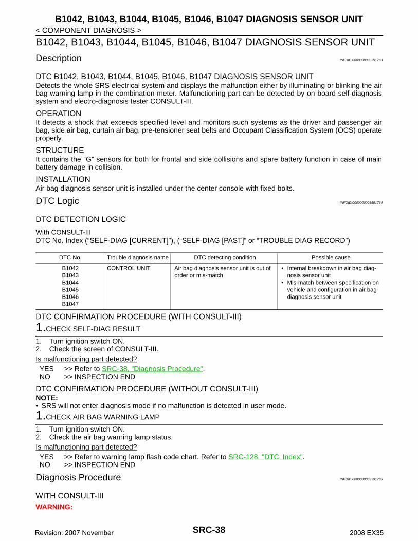
Description INFOID:0000000003591763
DTC B1042, B1043, B1044, B1045, B1046, B1047 DIAGNOSIS SENSOR UNITDetects the whole SRS electrical system and displays the malfunction either by illuminating or blinking the airbag warning lamp in the combination meter. Malfunctioning part can be detected by on board self-diagnosissystem and electro-diagnosis tester CONSULT-III.
OPERATIONIt detects a shock that exceeds specified level and monitors such systems as the driver and passenger airbag, side air bag, curtain air bag, pre-tensioner seat belts and Occupant Classification System (OCS) operateproperly.
STRUCTUREIt contains the “G” sensors for both for frontal and side collisions and spare battery function in case of mainbattery damage in collision.
INSTALLATIONAir bag diagnosis sensor unit is installed under the center console with fixed bolts.
DTC Logic INFOID:0000000003591764
DTC DETECTION LOGIC
With CONSULT-IIIDTC No. Index (“SELF-DIAG [CURRENT]”), (“SELF-DIAG [PAST]” or “TROUBLE DIAG RECORD”)
DTC CONFIRMATION PROCEDURE (WITH CONSULT-III)
1.CHECK SELF-DIAG RESULT
1. Turn ignition switch ON.2. Check the screen of CONSULT-III.Is malfunctioning part detected?YES >> Refer to SRC-38, "Diagnosis Procedure".NO >> INSPECTION END
DTC CONFIRMATION PROCEDURE (WITHOUT CONSULT-III)NOTE:• SRS will not enter diagnosis mode if no malfunction is detected in user mode.
1.CHECK AIR BAG WARNING LAMP
1. Turn ignition switch ON.2. Check the air bag warning lamp status.Is malfunctioning part detected?YES >> Refer to warning lamp flash code chart. Refer to SRC-128, "DTC Index".NO >> INSPECTION END
Diagnosis Procedure INFOID:0000000003591765
WITH CONSULT-IIIWARNING:
DTC No. Trouble diagnosis name DTC detecting condition Possible cause
B1042B1043B1044B1045B1046B1047
CONTROL UNIT Air bag diagnosis sensor unit is out of order or mis-match
• Internal breakdown in air bag diag-nosis sensor unit
• Mis-match between specification on vehicle and configuration in air bag diagnosis sensor unit
SRC-38Revision: 2007 November 2008 EX35
B1042, B1043, B1044, B1045, B1046, B1047 DIAGNOSIS SENSOR UNIT
C
D
E
F
G
I
J
K
L
M
A
B
RC
N
O
P
< COMPONENT DIAGNOSIS >
S
• Before servicing, turn ignition switch OFF, disconnect battery negative terminal and wait at least 3minutes. (To discharge backup capacitor.)
• Do not use unspecified tester or other measuring device.
DIAGNOSTIC PROCEDURE
1.CHECK HARNESS CONNECTOR
Check the connection of harness connector.Is the inspection result normal?YES >> GO TO 2.NO >> Replace harness connectors.
2.CHECK WIRING HARNESS
Check the wiring harness externals.Is the inspection result normal?YES >> GO TO 3.NO >> Replace wiring harness.
3.CHECK AIR BAG DIAGNOSIS SENSOR UNIT
1. Replace air bag diagnosis sensor unit. Refer to SR-4, "Exploded View".2. Check “Self diagnostic result” with CONSULT-III.3. Perform DTC confirmation procedure. Refer to SRC-38, "DTC Logic".Is DTC detected?YES >> GO TO 1.NO >> INSPECTION END
SRC-39Revision: 2007 November 2008 EX35

B1049, B1054 DRIVER AIRBAG MODULE
< COMPONENT DIAGNOSIS >B1049, B1054 DRIVER AIRBAG MODULE
Description INFOID:0000000003591767
DTC B1049, B1054 [OPEN] DRIVER AIRBAG MODULEFor driver air bag module, crash is judged by main "G" sensor output signal and Safing algorithm in front direc-tion.
OPERATIONIn case of frontal collision whose acceleration exceeds the specified level, the ignition materials are ignited byelectric ignition system. The system burns and introduces the chemical reaction of gas generating materials togenerate hot gases that flow into the air bag through a filter and expand the bag.
STRUCTUREDriver air bag module mainly consists of air bag and inflator which inflates air bag.
INSTALLATIONDriver air bag module is installed on the center of steering wheel with fixed bolts.
DTC Logic INFOID:0000000003591768
DTC DETECTION LOGIC
With CONSULT-IIIDTC No. Index (“SELF-DIAG [CURRENT]”), (“SELF-DIAG [PAST]” or “TROUBLE DIAG RECORD”)
DTC CONFIRMATION PROCEDURE (WITH CONSULT-III)
1.CHECK SELF-DIAG RESULT
1. Turn ignition switch ON.2. Check the screen of CONSULT-III.Is malfunctioning part detected?YES >> Refer to SRC-40, "Diagnosis Procedure".NO >> INSPECTION END
DTC CONFIRMATION PROCEDURE (WITHOUT CONSULT-III)NOTE:• SRS will not enter diagnosis mode if no malfunction is detected in user mode.
1.CHECK AIR BAG WARNING LAMP
1. Turn ignition switch ON.2. Check the air bag warning lamp status.Is malfunctioning part detected?YES >> Refer to warning lamp flash code chart. Refer to SRC-128, "DTC Index".NO >> INSPECTION END
Diagnosis Procedure INFOID:0000000003591769
WITH CONSULT-IIIWARNING:• Before servicing, turn ignition switch OFF, disconnect battery negative terminal and wait at least 3
minutes. (To discharge backup capacitor.)
DTC No. Trouble diagnosis name DTC detecting condition Possible cause
B1049B1054
DRIVER AIRBAG MOD-ULE[OPEN]
Driver air bag module circuit is open(including the spiral cable)
• Disconnection of wiring harness and open
• Internal breakdown in driver air bag module
• Internal breakdown in spiral cable• Internal breakdown in air bag diag-
nosis sensor unit
SRC-40Revision: 2007 November 2008 EX35

B1049, B1054 DRIVER AIRBAG MODULE
C
D
E
F
G
I
J
K
L
M
A
B
RC
N
O
P
< COMPONENT DIAGNOSIS >
S
• Do not use unspecified tester or other measuring device.
DIAGNOSTIC PROCEDURE
1.CHECK HARNESS CONNECTOR
Check the connection of harness connector.Is the inspection result normal?YES >> GO TO 2.NO >> Replace harness connector.
2.CHECK WIRING HARNESS
Check the wiring harness externals.Is the inspection result normal?YES >> GO TO 3.NO >> Replace wiring harness.
3.CHECK SPIRAL CABLE CIRCUIT
1. Turn ignition switch OFF.2. Disconnect driver side air bag module harness connector and body side harness connector.3. Check continuity between driver side air bag module harness connector and body side harness connec-
tor.
4. Check continuity between driver side air bag module harness connector and ground.
Is the inspection result normal?YES >> GO TO 4.NO >> Replace spiral cable. Refer to SR-6, "Exploded View".
4.CHECK DRIVER AIR BAG MODULE
1. Replace driver air bag module. Refer to SR-4, "Exploded View"2. Check “Self diagnostic result” with CONSULT-III.3. Perform DTC confirmation procedure. Refer to SRC-40, "DTC Logic".Is DTC detected?YES >> GO TO 5.NO >> INSPECTION END
5.CHECK AIR BAG DIAGNOSIS SENSOR UNIT
1. Replace driver air bag diagnosis sensor unit. Refer to SR-16, "Exploded View"2. Check “Self diagnostic result” with CONSULT-III.3. Perform DTC confirmation procedure. Refer to SRC-40, "DTC Logic".Is DTC detected?YES >> GO TO 1.NO >> INSPECTION END
Driver side air bag module harness connector
TerminalBody side harness
connectorTerminal Continuity
M30210
M35
28
Existed11 30
M30112 29
9 30
Driver side air bag module harness con-nector
Terminal
Ground
Continuity
M30210
Not existed11
M30112
9
SRC-41Revision: 2007 November 2008 EX35

B1050, B1055 DRIVER AIRBAG MODULE
< COMPONENT DIAGNOSIS >B1050, B1055 DRIVER AIRBAG MODULE
Description INFOID:0000000003591770
DTC B1050, B1055 [VB-SHORT] DRIVER AIRBAG MODULEFor driver air bag module, crash is judged by main “G” sensor output signal and Safing algorithm in front direc-tion.
OPERATIONIn case of frontal collision whose acceleration exceeds the specified level, the ignition materials are ignited byelectric ignition system. The system burns and introduces the chemical reaction of gas generating materials togenerate hot gases that flow into the air bag through a filter and expand the bag.
STRUCTUREDriver air bag module mainly consists of air bag and inflator which inflates air bag.
INSTALLATIONDriver air bag module is installed on the center of steering wheel with fixed bolts.
DTC Logic INFOID:0000000003591771
DTC DETECTION LOGIC
With CONSULT-IIIDTC No. Index (“SELF-DIAG [CURRENT]”), (“SELF-DIAG [PAST]” or “TROUBLE DIAG RECORD”)
DTC CONFIRMATION PROCEDURE (WITH CONSULT-III)
1.CHECK SELF-DIAG RESULT
1. Turn ignition switch ON.2. Check the screen of CONSULT-III.Is malfunctioning part detected?YES >> Refer to SRC-42, "Diagnosis Procedure".NO >> INSPECTION END
DTC CONFIRMATION PROCEDURE (WITHOUT CONSULT-III)NOTE:• SRS will not enter diagnosis mode if no malfunction is detected in user mode.
1.CHECK AIR BAG WARNING LAMP
1. Turn ignition switch ON.2. Check the air bag warning lamp status.Is malfunctioning part detected?YES >> Refer to warning lamp flash code chart. Refer to SRC-128, "DTC Index".NO >> INSPECTION END
Diagnosis Procedure INFOID:0000000003591772
WITH CONSULT-IIIWARNING:• Before servicing, turn ignition switch OFF, disconnect battery negative terminal and wait at least 3
minutes. (To discharge backup capacitor.)
DTC No. Trouble diagnosis name DTC detecting condition Possible cause
B1050B1055
DRIVER AIRBAG MOD-ULE [VB-SHORT]
Driver air bag module circuit is shorted to some power supply circuit(including the spiral cable)
• Disconnection of wiring harness and short
• Internal breakdown in driver air bag module
• Internal breakdown in spiral cable• Internal breakdown in air bag diag-
nosis sensor unit
SRC-42Revision: 2007 November 2008 EX35

B1050, B1055 DRIVER AIRBAG MODULE
C
D
E
F
G
I
J
K
L
M
A
B
RC
N
O
P
< COMPONENT DIAGNOSIS >
S
• Do not use unspecified tester or other measuring device.
DIAGNOSTIC PROCEDURE
1.CHECK HARNESS CONNECTOR
Check the connection of harness connector.Is the inspection result normal?YES >> GO TO 2.NO >> Replace harness connector.
2.CHECK WIRING HARNESS
Check the wiring harness externals.Is the inspection result normal?YES >> GO TO 3.NO >> Replace wiring harness.
3.CHECK SPIRAL CABLE CIRCUIT
1. Turn ignition switch OFF.2. Disconnect driver side air bag module harness connector and body side harness connector.3. Check continuity between driver side air bag module harness connector and body side harness connec-
tor.
4. Check continuity between driver side air bag module harness connector and ground.
Is the inspection result normal?YES >> GO TO 4.NO >> Replace spiral cable. Refer to SR-6, "Removal and Installation".
4.CHECK DRIVER AIR BAG MODULE
1. Replace driver air bag module. Refer to SR-4, "Exploded View".2. Check “Self diagnostic result” with CONSULT-III.3. Perform DTC confirmation procedure. Refer to SRC-42, "DTC Logic".Is DTC detected?YES >> GO TO 5.NO >> INSPECTION END
5.CHECK AIR BAG DIAGNOSIS SENSOR UNIT
1. Replace driver air bag diagnosis sensor unit. Refer to SR-16, "Exploded View".2. Check “Self diagnostic result” with CONSULT-III.3. Perform DTC confirmation procedure. Refer to SRC-42, "DTC Logic".Is DTC detected?YES >> GO TO 1.NO >> INSPECTION END
Driver side air bag module harness connector
TerminalBody side harness
connectorTerminal Continuity
M30210
M35
28
Existed11 30
M30112 29
9 30
Driver side air bag module harness con-nector
Terminal
Ground
Continuity
M30210
Not existed11
M30112
9
SRC-43Revision: 2007 November 2008 EX35

B1051, B1056 DRIVER AIRBAG MODULE
< COMPONENT DIAGNOSIS >B1051, B1056 DRIVER AIRBAG MODULE
Description INFOID:0000000003591773
DTC B1051, B1056 [GND-SHORT] DRIVER AIRBAG MODULEFor driver air bag module, crash is judged by main “G” sensor output signal and Safing algorithm in front direc-tion.
OPERATIONIn case of frontal collision whose acceleration exceeds the specified level, the ignition materials are ignited byelectric ignition system. The system burns and introduces the chemical reaction of gas generating materials togenerate hot gases that flow into the air bag through a filter and expand the bag.
STRUCTUREDriver air bag module mainly consists of air bag and inflator which inflates air bag.
INSTALLATIONDriver air bag module is installed on the center of steering wheel with fixed bolts.
DTC Logic INFOID:0000000003591774
DTC DETECTION LOGIC
With CONSULT-IIIDTC No. Index (“SELF-DIAG [CURRENT]”), (“SELF-DIAG [PAST]” or “TROUBLE DIAG RECORD”)
DTC CONFIRMATION PROCEDURE (WITH CONSULT-III)
1.CHECK SELF-DIAG RESULT
1. Turn ignition switch ON.2. Check the screen of CONSULT-III.Is malfunctioning part detected?YES >> Refer to SRC-44, "Diagnosis Procedure".NO >> INSPECTION END
DTC CONFIRMATION PROCEDURE (WITHOUT CONSULT-III)NOTE:• SRS will not enter diagnosis mode if no malfunction is detected in user mode.
1.CHECK AIR BAG WARNING LAMP
1. Turn ignition switch ON.2. Check the air bag warning lamp status.Is malfunctioning part detected?YES >> Refer to warning lamp flash code chart. Refer to SRC-128, "DTC Index".NO >> INSPECTION END
Diagnosis Procedure INFOID:0000000003591775
WITH CONSULT-IIIWARNING:• Before servicing, turn ignition switch OFF, disconnect battery negative terminal and wait at least 3
minutes. (To discharge backup capacitor.)
DTC No. Trouble diagnosis name DTC detecting condition Possible cause
B1051B1056
DRIVER AIRBAG MOD-ULE [GND-SHORT]
Driver air bag module circuit is shorted to ground(including the spiral cable)
• Disconnection of wiring harness and short
• Internal breakdown in driver air bag module
• Internal breakdown in spiral cable• Internal breakdown in air bag diag-
nosis sensor unit
SRC-44Revision: 2007 November 2008 EX35

B1051, B1056 DRIVER AIRBAG MODULE
C
D
E
F
G
I
J
K
L
M
A
B
RC
N
O
P
< COMPONENT DIAGNOSIS >
S
• Do not use unspecified tester or other measuring device.
DIAGNOSTIC PROCEDURE
1.CHECK HARNESS CONNECTOR
Check the connection of harness connector.Is the inspection result normal?YES >> GO TO 2.NO >> Replace harness connector.
2.CHECK WIRING HARNESS
Check the wiring harness externals.Is the inspection result normal?YES >> GO TO 3.NO >> Replace wiring harness.
3.CHECK SPIRAL CABLE CIRCUIT
1. Turn ignition switch OFF.2. Disconnect driver side air bag module harness connector and body side harness connector.3. Check continuity between driver side air bag module harness connector and body side harness connec-
tor.
4. Check continuity between driver side air bag module harness connector and ground.
Is the inspection result normal?YES >> GO TO 4.NO >> Replace spiral cable. Refer to SR-6, "Removal and Installation".
4.CHECK DRIVER AIR BAG MODULE
1. Replace driver air bag module. Refer to SR-4, "Exploded View".2. Check “Self diagnostic result” with CONSULT-III.3. Perform DTC confirmation procedure. Refer to SRC-44, "DTC Logic".Is DTC detected?YES >> GO TO 5.NO >> INSPECTION END
5.CHECK AIR BAG DIAGNOSIS SENSOR UNIT
1. Replace driver air bag diagnosis sensor unit. Refer to SR-16, "Exploded View".2. Check “Self diagnostic result” with CONSULT-III.3. Perform DTC confirmation procedure. Refer to SRC-44, "DTC Logic".Is DTC detected?YES >> GO TO 1.NO >> INSPECTION END
Driver side air bag module harness connector
TerminalBody side harness
connectorTerminal Continuity
M30210
M35
28
Existed11 30
M30112 29
9 30
Driver side air bag module harness con-nector
Terminal
Ground
Continuity
M30210
Not existed11
M30112
9
SRC-45Revision: 2007 November 2008 EX35
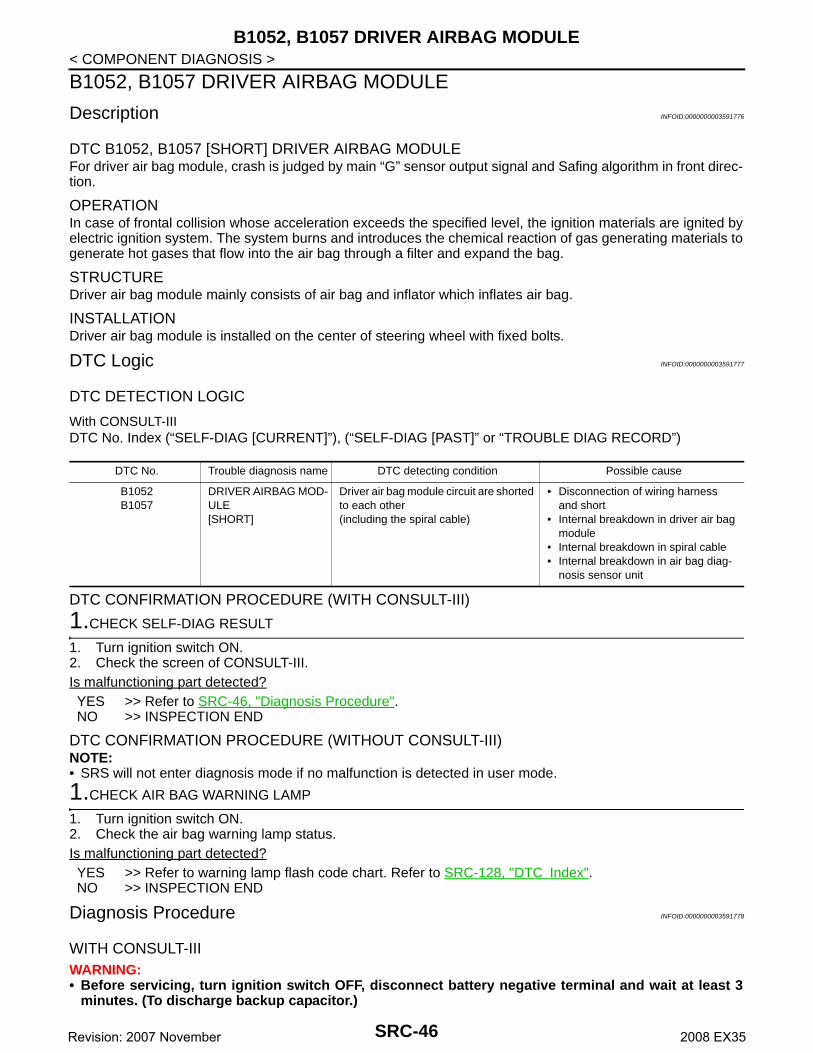
B1052, B1057 DRIVER AIRBAG MODULE
< COMPONENT DIAGNOSIS >B1052, B1057 DRIVER AIRBAG MODULE
Description INFOID:0000000003591776
DTC B1052, B1057 [SHORT] DRIVER AIRBAG MODULEFor driver air bag module, crash is judged by main “G” sensor output signal and Safing algorithm in front direc-tion.
OPERATIONIn case of frontal collision whose acceleration exceeds the specified level, the ignition materials are ignited byelectric ignition system. The system burns and introduces the chemical reaction of gas generating materials togenerate hot gases that flow into the air bag through a filter and expand the bag.
STRUCTUREDriver air bag module mainly consists of air bag and inflator which inflates air bag.
INSTALLATIONDriver air bag module is installed on the center of steering wheel with fixed bolts.
DTC Logic INFOID:0000000003591777
DTC DETECTION LOGIC
With CONSULT-IIIDTC No. Index (“SELF-DIAG [CURRENT]”), (“SELF-DIAG [PAST]” or “TROUBLE DIAG RECORD”)
DTC CONFIRMATION PROCEDURE (WITH CONSULT-III)
1.CHECK SELF-DIAG RESULT
1. Turn ignition switch ON.2. Check the screen of CONSULT-III.Is malfunctioning part detected?YES >> Refer to SRC-46, "Diagnosis Procedure".NO >> INSPECTION END
DTC CONFIRMATION PROCEDURE (WITHOUT CONSULT-III)NOTE:• SRS will not enter diagnosis mode if no malfunction is detected in user mode.
1.CHECK AIR BAG WARNING LAMP
1. Turn ignition switch ON.2. Check the air bag warning lamp status.Is malfunctioning part detected?YES >> Refer to warning lamp flash code chart. Refer to SRC-128, "DTC Index".NO >> INSPECTION END
Diagnosis Procedure INFOID:0000000003591778
WITH CONSULT-IIIWARNING:• Before servicing, turn ignition switch OFF, disconnect battery negative terminal and wait at least 3
minutes. (To discharge backup capacitor.)
DTC No. Trouble diagnosis name DTC detecting condition Possible cause
B1052B1057
DRIVER AIRBAG MOD-ULE [SHORT]
Driver air bag module circuit are shorted to each other(including the spiral cable)
• Disconnection of wiring harnessand short
• Internal breakdown in driver air bag module
• Internal breakdown in spiral cable• Internal breakdown in air bag diag-
nosis sensor unit
SRC-46Revision: 2007 November 2008 EX35

B1052, B1057 DRIVER AIRBAG MODULE
C
D
E
F
G
I
J
K
L
M
A
B
RC
N
O
P
< COMPONENT DIAGNOSIS >
S
• Do not use unspecified tester or other measuring device.
DIAGNOSTIC PROCEDURE
1.CHECK HARNESS CONNECTOR
Check the connection of harness connector.Is the inspection result normal?YES >> GO TO 2.NO >> Replace harness connector.
2.CHECK WIRING HARNESS
Check the wiring harness externals.Is the inspection result normal?YES >> GO TO 3.NO >> Replace wiring harness.
3.CHECK SPIRAL CABLE CIRCUIT
1. Turn ignition switch OFF.2. Disconnect driver side air bag module harness connector and body side harness connector.3. Check continuity between driver side air bag module harness connector and body side harness connec-
tor.
4. Check continuity between driver side air bag module harness connector and ground.
Is the inspection result normal?YES >> GO TO 4.NO >> Replace spiral cable. Refer to SR-6, "Removal and Installation".
4.CHECK DRIVER AIR BAG MODULE
1. Replace driver air bag module. Refer to SR-4, "Exploded View".2. Check “Self diagnostic result” with CONSULT-III.3. Perform DTC confirmation procedure. Refer to SRC-46, "DTC Logic".Is DTC detected?YES >> GO TO 5.NO >> INSPECTION END
5.CHECK AIR BAG DIAGNOSIS SENSOR UNIT
1. Replace driver air bag diagnosis sensor unit. Refer to SR-16, "Exploded View".2. Check “Self diagnostic result” with CONSULT-III.3. Perform DTC confirmation procedure. Refer to SRC-46, "DTC Logic".Is DTC detected?YES >> GO TO 1.NO >> INSPECTION END
Driver side air bag module harness connector
TerminalBody side harness
connectorTerminal Continuity
M30210
M35
28
Existed11 30
M30112 29
9 30
Driver side air bag module harness con-nector
Terminal
Ground
Continuity
M30210
Not existed11
M30112
9
SRC-47Revision: 2007 November 2008 EX35

B1058, B1059, B1060, B1061, B1062, B1063 DIAGNOSIS SENSOR UNIT
< COMPONENT DIAGNOSIS >B1058, B1059, B1060, B1061, B1062, B1063 DIAGNOSIS SENSOR UNIT
Description INFOID:0000000003591779
DTC B1058, B1059, B1060, B1061, B1062, B1063 DIAGNOSIS SENSOR UNITDetects the whole SRS electrical system and displays the malfunction either by illuminating or blinking the airbag warning lamp in the combination meter. Malfunctioning part can be detected by on board self-diagnosissystem and electro-diagnosis tester CONSULT-III.
OPERATIONIt detects a shock that exceeds specified level and monitors such systems as the driver and passenger airbag, side air bag, curtain air bag, pre-tensioner seat belts and Occupant Classification System (OCS) operateproperly.
STRUCTUREIt contains the “G” sensors for both frontal and side collisions and spare battery function in case of main bat-tery damage in collision.
INSTALLATIONAir bag diagnosis sensor unit is installed under the center console with fixed bolts.
DTC Logic INFOID:0000000003591780
DTC DETECTION LOGIC
With CONSULT-IIIDTC No. Index (“SELF-DIAG [CURRENT]”), (“SELF-DIAG [PAST]” or “TROUBLE DIAG RECORD”)
DTC CONFIRMATION PROCEDURE (WITH CONSULT-III)
1.CHECK SELF-DIAG RESULT
1. Turn ignition switch ON.2. Check the screen of CONSULT-III.Is malfunctioning part detected?YES >> Refer to SRC-48, "Diagnosis Procedure".NO >> INSPECTION END
DTC CONFIRMATION PROCEDURE (WITHOUT CONSULT-III)NOTE:• SRS will not enter diagnosis mode if no malfunction is detected in user mode.
1.CHECK AIR BAG WARNING LAMP
1. Turn ignition switch ON.2. Check the air bag warning lamp status.Is malfunctioning part detected?YES >> Refer to warning lamp flash code chart. Refer to SRC-128, "DTC Index".NO >> INSPECTION END
Diagnosis Procedure INFOID:0000000003591781
WITH CONSULT-IIIWARNING:
DTC No. Trouble diagnosis name DTC detecting condition Possible cause
B1058B1059B1060B1061B1062B1063
CONTROL UNIT Air bag diagnosis sensor unit is out of order or mis-match
• Internal breakdown in air bag diag-nosis sensor unit
• Mis-match between specification on vehicle and configuration in air bag diagnosis sensor unit
SRC-48Revision: 2007 November 2008 EX35

B1058, B1059, B1060, B1061, B1062, B1063 DIAGNOSIS SENSOR UNIT
C
D
E
F
G
I
J
K
L
M
A
B
RC
N
O
P
< COMPONENT DIAGNOSIS >
S
• Before servicing, turn ignition switch OFF, disconnect battery negative terminal and wait at least 3minutes. (To discharge backup capacitor.)
• Do not use unspecified tester or other measuring device.
DIAGNOSTIC PROCEDURE
1.CHECK HARNESS CONNECTOR
Check the connection of harness connector.Is the inspection result normal?YES >> GO TO 2.NO >> Replace harness connectors.
2.CHECK WIRING HARNESS
Check the wiring harness externals.Is the inspection result normal?YES >> GO TO 3.NO >> Replace wiring harness.
3.CHECK AIR BAG DIAGNOSIS SENSOR UNIT
1. Replace air bag diagnosis sensor unit. Refer to SR-16, "Exploded View".2. Check “Self diagnostic result” with CONSULT-III.3. Perform DTC confirmation procedure. Refer to SRC-48, "DTC Logic".Is DTC detected?YES >> GO TO 1.NO >> INSPECTION END
SRC-49Revision: 2007 November 2008 EX35

B1065, B1070 ASSIST A/B MODULE
< COMPONENT DIAGNOSIS >B1065, B1070 ASSIST A/B MODULE
Description INFOID:0000000003591782
DTC B 1065, B1070 [OPEN] ASSIST A/B MODULEFor front passenger air bag module, crash is judged by main “G” sensor output signal and Safing algorithm infront direction.
OPERATIONIn the case of a frontal collision whose acceleration exceeds the specified level, the ignition materials areignited by electric ignition system. The system burns and introduces the chemical reaction of gas generatingmaterials to generate hot gases that flow into the air bag through a filter and expand the bag.
STRUCTUREFront passenger air bag module mainly consists of air bag and inflator which inflates air bag.
INSTALLATIONFront passenger air bag module is installed on the instrument panel with fixed bolts.
DTC Logic INFOID:0000000003591783
DTC DETECTION LOGIC
With CONSULT-IIIDTC No. Index (“SELF-DIAG [CURRENT]”), (“SELF-DIAG [PAST]” or “TROUBLE DIAG RECORD”)
DTC CONFIRMATION PROCEDURE (WITH CONSULT-III)
1.CHECK SELF-DIAG RESULT
1. Turn ignition switch ON.2. Check the screen of CONSULT-III.Is malfunctioning part detected?YES >> Refer to SRC-50, "Diagnosis Procedure".NO >> INSPECTION END
DTC CONFIRMATION PROCEDURE (WITHOUT CONSULT-III)NOTE:• SRS will not enter diagnosis mode if no malfunction is detected in user mode.
1.CHECK AIR BAG WARNING LAMP
1. Turn ignition switch ON.2. Check the air bag warning lamp status.Is malfunctioning part detected?YES >> Refer to warning lamp flash code chart. Refer to SRC-128, "DTC Index".NO >> INSPECTION END
Diagnosis Procedure INFOID:0000000003591784
WITH CONSULT-IIIWARNING:• Before servicing, turn ignition switch OFF, disconnect battery negative terminal and wait at least 3
minutes. (To discharge backup capacitor.)• Do not use unspecified tester or other measuring device.
DTC No. Trouble diagnosis name DTC detecting condition Possible cause
B1065B1070
ASSIST A/B MODULE [OPEN]
Front passenger air bag module circuit is open
• Disconnection of wiring harness and open
• Internal breakdown in front passen-ger air bag module
• Internal breakdown in air bag diag-nosis sensor unit
SRC-50Revision: 2007 November 2008 EX35

B1065, B1070 ASSIST A/B MODULE
C
D
E
F
G
I
J
K
L
M
A
B
RC
N
O
P
< COMPONENT DIAGNOSIS >
S
DIAGNOSTIC PROCEDURE
1.CHECK HARNESS CONNECTOR
Check the connection of harness connector.Is the inspection result normal?YES >> GO TO 2.NO >> Replace harness connector.
2.CHECK WIRING HARNESS
Check the wiring harness externals.Is the inspection result normal?YES >> GO TO 3.NO >> Replace wiring harness.
3.CHECK FRONT PASSENGER AIR BAG MODULE
1. Replace front passenger air bag module. Refer to SR-8, "Exploded View"2. Check “Self diagnostic result” with CONSULT-III.3. Perform DTC confirmation procedure. Refer to SRC-50, "DTC Logic".Is DTC detected?YES >> GO TO 4.NO >> INSPECTION END
4.CHECK AIR BAG DIAGNOSIS SENSOR UNIT
1. Replace air bag diagnosis sensor unit. Refer to SR-4, "Exploded View".2. Check “Self diagnostic result” with CONSULT-III.3. Perform DTC confirmation procedure. Refer to SRC-50, "DTC Logic".Is DTC detected?YES >> GO TO 1.NO >> INSPECTION END
SRC-51Revision: 2007 November 2008 EX35

B1066, B1071 ASSIST A/B MODULE
< COMPONENT DIAGNOSIS >B1066, B1071 ASSIST A/B MODULE
Description INFOID:0000000003591785
DTC B1066, B1071 [VB-SHORT] ASSIST A/B MODULEFor front passenger air bag module, crash is judged by main “G” sensor output signal and Safing algorithm infront direction.
OPERATIONIn the case of a frontal collision whose acceleration exceeds the specified level, the ignition materials areignited by electric ignition system. The system burns and introduces the chemical reaction of gas generatingmaterials to generate hot gases that flow into the air bag through a filter and expand the bag.
STRUCTUREFront passenger air bag module mainly consists of air bag and inflator which inflates air bag.
INSTALLATIONFront passenger air bag module is installed on the instrument panel with fixed bolts.
DTC Logic INFOID:0000000003591786
DTC DETECTION LOGIC
With CONSULT-IIIDTC No. Index (“SELF-DIAG [CURRENT]”), (“SELF-DIAG [PAST]” or “TROUBLE DIAG RECORD”)
DTC CONFIRMATION PROCEDURE (WITH CONSULT-III)
1.CHECK SELF-DIAG RESULT
1. Turn ignition switch ON.2. Check the screen of CONSULT-III.Is malfunctioning part detected?YES >> Refer to SRC-52, "Diagnosis Procedure".NO >> INSPECTION END
DTC CONFIRMATION PROCEDURE (WITHOUT CONSULT-III)NOTE:• SRS will not enter diagnosis mode if no malfunction is detected in user mode.
1.CHECK AIR BAG WARNING LAMP
1. Turn ignition switch ON.2. Check the air bag warning lamp status.Is malfunctioning part detected?YES >> Refer to warning lamp flash code chart. Refer to SRC-128, "DTC Index".NO >> INSPECTION END
Diagnosis Procedure INFOID:0000000003591787
WITH CONSULT-IIIWARNING:• Before servicing, turn ignition switch OFF, disconnect battery negative terminal and wait at least 3
minutes. (To discharge backup capacitor.)• Do not use unspecified tester or other measuring device.
DTC No. Trouble diagnosis name DTC detecting condition Possible cause
B1066B1071
ASSIST A/B MODULE [VB-SHORT]
Front passenger air bag module circuit is shorted to some power supply circuit
• Disconnection of wiring harness and short
• Internal breakdown in front passen-ger air bag module
• Internal breakdown in air bag diag-nosis sensor unit
SRC-52Revision: 2007 November 2008 EX35
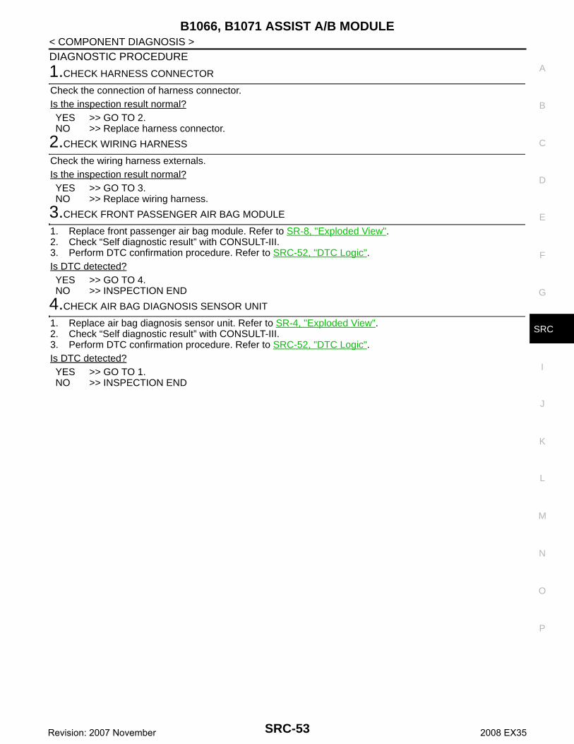
B1066, B1071 ASSIST A/B MODULE
C
D
E
F
G
I
J
K
L
M
A
B
RC
N
O
P
< COMPONENT DIAGNOSIS >
S
DIAGNOSTIC PROCEDURE
1.CHECK HARNESS CONNECTOR
Check the connection of harness connector.Is the inspection result normal?YES >> GO TO 2.NO >> Replace harness connector.
2.CHECK WIRING HARNESS
Check the wiring harness externals.Is the inspection result normal?YES >> GO TO 3.NO >> Replace wiring harness.
3.CHECK FRONT PASSENGER AIR BAG MODULE
1. Replace front passenger air bag module. Refer to SR-8, "Exploded View".2. Check “Self diagnostic result” with CONSULT-III.3. Perform DTC confirmation procedure. Refer to SRC-52, "DTC Logic".Is DTC detected?YES >> GO TO 4.NO >> INSPECTION END
4.CHECK AIR BAG DIAGNOSIS SENSOR UNIT
1. Replace air bag diagnosis sensor unit. Refer to SR-4, "Exploded View".2. Check “Self diagnostic result” with CONSULT-III.3. Perform DTC confirmation procedure. Refer to SRC-52, "DTC Logic".Is DTC detected?YES >> GO TO 1.NO >> INSPECTION END
SRC-53Revision: 2007 November 2008 EX35
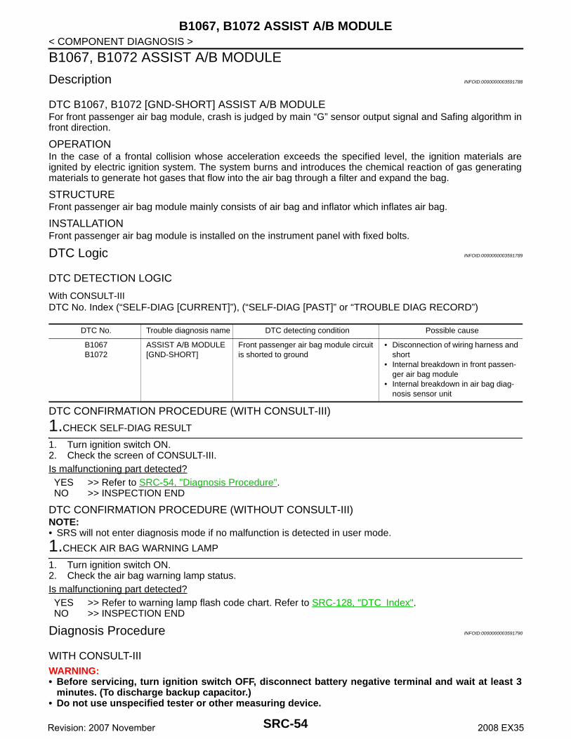
B1067, B1072 ASSIST A/B MODULE
< COMPONENT DIAGNOSIS >B1067, B1072 ASSIST A/B MODULE
Description INFOID:0000000003591788
DTC B1067, B1072 [GND-SHORT] ASSIST A/B MODULEFor front passenger air bag module, crash is judged by main “G” sensor output signal and Safing algorithm infront direction.
OPERATIONIn the case of a frontal collision whose acceleration exceeds the specified level, the ignition materials areignited by electric ignition system. The system burns and introduces the chemical reaction of gas generatingmaterials to generate hot gases that flow into the air bag through a filter and expand the bag.
STRUCTUREFront passenger air bag module mainly consists of air bag and inflator which inflates air bag.
INSTALLATIONFront passenger air bag module is installed on the instrument panel with fixed bolts.
DTC Logic INFOID:0000000003591789
DTC DETECTION LOGIC
With CONSULT-IIIDTC No. Index (“SELF-DIAG [CURRENT]”), (“SELF-DIAG [PAST]” or “TROUBLE DIAG RECORD”)
DTC CONFIRMATION PROCEDURE (WITH CONSULT-III)
1.CHECK SELF-DIAG RESULT
1. Turn ignition switch ON.2. Check the screen of CONSULT-III.Is malfunctioning part detected?YES >> Refer to SRC-54, "Diagnosis Procedure".NO >> INSPECTION END
DTC CONFIRMATION PROCEDURE (WITHOUT CONSULT-III)NOTE:• SRS will not enter diagnosis mode if no malfunction is detected in user mode.
1.CHECK AIR BAG WARNING LAMP
1. Turn ignition switch ON.2. Check the air bag warning lamp status.Is malfunctioning part detected?YES >> Refer to warning lamp flash code chart. Refer to SRC-128, "DTC Index".NO >> INSPECTION END
Diagnosis Procedure INFOID:0000000003591790
WITH CONSULT-IIIWARNING:• Before servicing, turn ignition switch OFF, disconnect battery negative terminal and wait at least 3
minutes. (To discharge backup capacitor.)• Do not use unspecified tester or other measuring device.
DTC No. Trouble diagnosis name DTC detecting condition Possible cause
B1067B1072
ASSIST A/B MODULE [GND-SHORT]
Front passenger air bag module circuit is shorted to ground
• Disconnection of wiring harness and short
• Internal breakdown in front passen-ger air bag module
• Internal breakdown in air bag diag-nosis sensor unit
SRC-54Revision: 2007 November 2008 EX35

B1067, B1072 ASSIST A/B MODULE
C
D
E
F
G
I
J
K
L
M
A
B
RC
N
O
P
< COMPONENT DIAGNOSIS >
S
DIAGNOSTIC PROCEDURE
1.CHECK HARNESS CONNECTOR
Check the connection of harness connector.Is the inspection result normal?YES >> GO TO 2.NO >> Replace harness connector.
2.CHECK WIRING HARNESS
Check the wiring harness externals.Is the inspection result normal?YES >> GO TO 3.NO >> Replace wiring harness.
3.CHECK FRONT PASSENGER AIR BAG MODULE
1. Replace front passenger air bag module. Refer to SR-8, "Exploded View"2. Check “Self diagnostic result” with CONSULT-III.3. Perform DTC confirmation procedure. Refer to SRC-54, "DTC Logic".Is DTC detected?YES >> GO TO 4.NO >> INSPECTION END
4.CHECK AIR BAG DIAGNOSIS SENSOR UNIT
1. Replace air bag diagnosis sensor unit. Refer to SR-4, "Exploded View".2. Check “Self diagnostic result” with CONSULT-III.3. Perform DTC confirmation procedure. Refer to SRC-54, "DTC Logic".Is DTC detected?YES >> GO TO 1.NO >> INSPECTION END
SRC-55Revision: 2007 November 2008 EX35
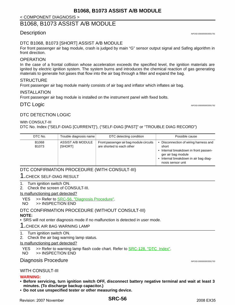
B1068, B1073 ASSIST A/B MODULE
< COMPONENT DIAGNOSIS >B1068, B1073 ASSIST A/B MODULE
Description INFOID:0000000003591791
DTC B1068, B1073 [SHORT] ASSIST A/B MODULEFor front passenger air bag module, crash is judged by main “G” sensor output signal and Safing algorithm infront direction.
OPERATIONIn the case of a frontal collision whose acceleration exceeds the specified level, the ignition materials areignited by electric ignition system. The system burns and introduces the chemical reaction of gas generatingmaterials to generate hot gases that flow into the air bag through a filter and expand the bag.
STRUCTUREFront passenger air bag module mainly consists of air bag and inflator which inflates air bag.
INSTALLATIONFront passenger air bag module is installed on the instrument panel with fixed bolts.
DTC Logic INFOID:0000000003591792
DTC DETECTION LOGIC
With CONSULT-IIIDTC No. Index (“SELF-DIAG [CURRENT]”), (“SELF-DIAG [PAST]” or “TROUBLE DIAG RECORD”)
DTC CONFIRMATION PROCEDURE (WITH CONSULT-III)
1.CHECK SELF-DIAG RESULT
1. Turn ignition switch ON.2. Check the screen of CONSULT-III.Is malfunctioning part detected?YES >> Refer to SRC-56, "Diagnosis Procedure".NO >> INSPECTION END
DTC CONFIRMATION PROCEDURE (WITHOUT CONSULT-III)NOTE:• SRS will not enter diagnosis mode if no malfunction is detected in user mode.
1.CHECK AIR BAG WARNING LAMP
1. Turn ignition switch ON.2. Check the air bag warning lamp status.Is malfunctioning part detected?YES >> Refer to warning lamp flash code chart. Refer to SRC-128, "DTC Index".NO >> INSPECTION END
Diagnosis Procedure INFOID:0000000003591793
WITH CONSULT-IIIWARNING:• Before servicing, turn ignition switch OFF, disconnect battery negative terminal and wait at least 3
minutes. (To discharge backup capacitor.)• Do not use unspecified tester or other measuring device.
DTC No. Trouble diagnosis name DTC detecting condition Possible cause
B1068B1073
ASSIST A/B MODULE [SHORT]
Front passenger air bag module circuits are shorted to each other
• Disconnection of wiring harness and short
• Internal breakdown in front passen-ger air bag module
• Internal breakdown in air bag diag-nosis sensor unit
SRC-56Revision: 2007 November 2008 EX35

B1068, B1073 ASSIST A/B MODULE
C
D
E
F
G
I
J
K
L
M
A
B
RC
N
O
P
< COMPONENT DIAGNOSIS >
S
DIAGNOSTIC PROCEDURE
1.CHECK HARNESS CONNECTOR
Check the connection of harness connector.Is the inspection result normal?YES >> GO TO 2.NO >> Replace harness connector.
2.CHECK WIRING HARNESS
Check the wiring harness externals.Is the inspection result normal?YES >> GO TO 3.NO >> Replace wiring harness.
3.CHECK FRONT PASSENGER AIR BAG MODULE
1. Replace front passenger air bag module. Refer to SR-8, "Exploded View"2. Check “Self diagnostic result” with CONSULT-III.3. Perform DTC confirmation procedure. Refer to SRC-56, "DTC Logic".Is DTC detected?YES >> GO TO 4.NO >> INSPECTION END
4.CHECK AIR BAG DIAGNOSIS SENSOR UNIT
1. Replace air bag diagnosis sensor unit. Refer to SR-4, "Exploded View".2. Check “Self diagnostic result” with CONSULT-III.3. Perform DTC confirmation procedure. Refer to SRC-56, "DTC Logic".Is DTC detected?YES >> GO TO 1.NO >> INSPECTION END
SRC-57Revision: 2007 November 2008 EX35
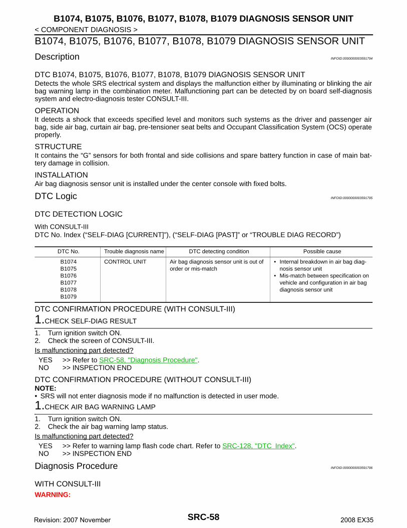
B1074, B1075, B1076, B1077, B1078, B1079 DIAGNOSIS SENSOR UNIT
< COMPONENT DIAGNOSIS >B1074, B1075, B1076, B1077, B1078, B1079 DIAGNOSIS SENSOR UNIT
Description INFOID:0000000003591794
DTC B1074, B1075, B1076, B1077, B1078, B1079 DIAGNOSIS SENSOR UNITDetects the whole SRS electrical system and displays the malfunction either by illuminating or blinking the airbag warning lamp in the combination meter. Malfunctioning part can be detected by on board self-diagnosissystem and electro-diagnosis tester CONSULT-III.
OPERATIONIt detects a shock that exceeds specified level and monitors such systems as the driver and passenger airbag, side air bag, curtain air bag, pre-tensioner seat belts and Occupant Classification System (OCS) operateproperly.
STRUCTUREIt contains the “G” sensors for both frontal and side collisions and spare battery function in case of main bat-tery damage in collision.
INSTALLATIONAir bag diagnosis sensor unit is installed under the center console with fixed bolts.
DTC Logic INFOID:0000000003591795
DTC DETECTION LOGIC
With CONSULT-IIIDTC No. Index (“SELF-DIAG [CURRENT]”), (“SELF-DIAG [PAST]” or “TROUBLE DIAG RECORD”)
DTC CONFIRMATION PROCEDURE (WITH CONSULT-III)
1.CHECK SELF-DIAG RESULT
1. Turn ignition switch ON.2. Check the screen of CONSULT-III.Is malfunctioning part detected?YES >> Refer to SRC-58, "Diagnosis Procedure".NO >> INSPECTION END
DTC CONFIRMATION PROCEDURE (WITHOUT CONSULT-III)NOTE:• SRS will not enter diagnosis mode if no malfunction is detected in user mode.
1.CHECK AIR BAG WARNING LAMP
1. Turn ignition switch ON.2. Check the air bag warning lamp status.Is malfunctioning part detected?YES >> Refer to warning lamp flash code chart. Refer to SRC-128, "DTC Index".NO >> INSPECTION END
Diagnosis Procedure INFOID:0000000003591796
WITH CONSULT-IIIWARNING:
DTC No. Trouble diagnosis name DTC detecting condition Possible cause
B1074B1075B1076B1077B1078B1079
CONTROL UNIT Air bag diagnosis sensor unit is out of order or mis-match
• Internal breakdown in air bag diag-nosis sensor unit
• Mis-match between specification on vehicle and configuration in air bag diagnosis sensor unit
SRC-58Revision: 2007 November 2008 EX35

B1074, B1075, B1076, B1077, B1078, B1079 DIAGNOSIS SENSOR UNIT
C
D
E
F
G
I
J
K
L
M
A
B
RC
N
O
P
< COMPONENT DIAGNOSIS >
S
• Before servicing, turn ignition switch OFF, disconnect battery negative terminal and wait at least 3minutes. (To discharge backup capacitor.)
• Do not use unspecified tester or other measuring device.
DIAGNOSTIC PROCEDURE
1.CHECK HARNESS CONNECTOR
Check the connection of harness connector.Is the inspection result normal?YES >> GO TO 2.NO >> Replace harness connectors.
2.CHECK WIRING HARNESS
Check the wiring harness externals.Is the inspection result normal?YES >> GO TO 3.NO >> Replace wiring harness.
3.CHECK AIR BAG DIAGNOSIS SENSOR UNIT
1. Replace front RH seat belt pre-tensioner. Refer to SB-5, "SEAT BELT RETRACTOR : Exploded View"2. Check the screen of CONSULT-III.Is the inspection result normal?YES >> INSPECTION ENDNO >> Check the intermittent incident. Refer to GI-38, "Intermittent Incident".
SRC-59Revision: 2007 November 2008 EX35

B1081 PRE-TEN FRONT RH
< COMPONENT DIAGNOSIS >B1081 PRE-TEN FRONT RH
Description INFOID:0000000003591798
DTC B1081 [OPEN] PRE-TEN FRONT RHFor front RH seat belt pre-tensioner, crash is judged by main “G” sensor output signal and Safing algorithm infront direction.
OPERATIONIn the case of a frontal collision that exceeds specified impact level, the air bag diagnosis sensor unit detectsthe deceleration caused by collision. It restrains the passenger with seat belt easing the stress on passengerschest with load limiter.
STRUCTUREThe restraint system for front seat occupant consists of the pre-tensioner mechanism and load limiter mecha-nism.
INSTALLATIONFront RH seat belt pre-tensioner is installed on the underside of center pillar with fixed nuts.
DTC Logic INFOID:0000000003591799
DTC DETECTION LOGIC
With CONSULT-IIIDTC No. Index (“SELF-DIAG [CURRENT]”), (“SELF-DIAG [PAST]” or “TROUBLE DIAG RECORD”)
DTC CONFIRMATION PROCEDURE (WITH CONSULT-III)
1.CHECK SELF-DIAG RESULT
1. Turn ignition switch ON.2. Check the screen of CONSULT-III.Is malfunctioning part detected?YES >> Refer to SRC-60, "Diagnosis Procedure".NO >> INSPECTION END
DTC CONFIRMATION PROCEDURE (WITHOUT CONSULT-III)NOTE:• SRS will not enter diagnosis mode if no malfunction is detected in user mode.
1.CHECK AIR BAG WARNING LAMP
1. Turn ignition switch ON.2. Check the air bag warning lamp status.Is malfunctioning part detected?YES >> Refer to warning lamp flash code chart. Refer to SRC-128, "DTC Index".NO >> INSPECTION END
Diagnosis Procedure INFOID:0000000003591800
WITH CONSULT-IIIWARNING:• Before servicing, turn ignition switch OFF, disconnect battery negative terminal and wait at least 3
minutes. (To discharge backup capacitor.)
DTC No. Trouble diagnosis name DTC detecting condition Possible cause
B1081 PRE-TEN FRONT RH [OPEN]
Front RH seat belt pre-tensioner circuit is open
• Disconnection of wiring harness and open
• Internal breakdown in front RH seat belt pre-tensioner
• Internal breakdown in air bag diag-nosis sensor unit
SRC-60Revision: 2007 November 2008 EX35

B1081 PRE-TEN FRONT RH
C
D
E
F
G
I
J
K
L
M
A
B
RC
N
O
P
< COMPONENT DIAGNOSIS >
S
• Do not use unspecified tester or other measuring device.
DIAGNOSTIC PROCEDURE
1.CHECK HARNESS CONNECTOR
Check the connection of harness connector.Is the inspection result normal?YES >> GO TO 2.NO >> Replace harness connector.
2.CHECK WIRING HARNESS
Check the wiring harness externals.Is the inspection result normal?YES >> GO TO 3.NO >> Replace wiring harness.
3.CHECK FRONT SEAT BELT PRE-TENSIONER
1. Replace front RH seat belt pre-tensioner. Refer to SB-5, "SEAT BELT RETRACTOR : Exploded View".2. Check “Self diagnosis result” with CONSULT-III.3. Perform DTC confirmation procedure. Refer to SRC-60, "DTC Logic".Is DTC detected?YES >> GO TO 4.NO >> INSPECTION END
4.CHECK AIR BAG DIAGNOSIS SENSOR UNIT
1. Replace air bag diagnosis sensor unit. Refer to SR-16, "Exploded View".2. Check “Self diagnosis result” with CONSULT-III.3. Perform DTC confirmation procedure. Refer to SRC-60, "DTC Logic".Is DTC detected?YES >> GO TO 1.NO >> INSPECTION END
SRC-61Revision: 2007 November 2008 EX35

B1082 PRE-TEN FRONT RH
< COMPONENT DIAGNOSIS >B1082 PRE-TEN FRONT RH
Description INFOID:0000000003591801
DTC B1082 [VB-SHORT] PRE-TEN FRONT RHFor front RH seat belt pre-tensioner, crash is judged by main "G" sensor output signal and Safing algorithm infront direction.
OPERATIONIn the case of a frontal collision that exceeds specified impact level, the air bag diagnosis sensor unit detectsthe deceleration caused by collision. It restrains the passenger with seat belt easing the stress on passengerschest with load limiter.
STRUCTUREThe restraint system for front seat occupant consists of the pre-tensioner mechanism and load limiter mecha-nism.
INSTALLATIONFront RH seat belt pre-tensioner is installed on the underside of center pillar with fixed nuts.
DTC Logic INFOID:0000000003591802
DTC DETECTION LOGIC
With CONSULT-IIIDTC No. Index (“SELF-DIAG [CURRENT]”), (“SELF-DIAG [PAST]” or “TROUBLE DIAG RECORD”)
DTC CONFIRMATION PROCEDURE (WITH CONSULT-III)
1.CHECK SELF-DIAG RESULT
1. Turn ignition switch ON.2. Check the screen of CONSULT-III.Is malfunctioning part detected?YES >> Refer to SRC-62, "Diagnosis Procedure".NO >> INSPECTION END
DTC CONFIRMATION PROCEDURE (WITHOUT CONSULT-III)NOTE:• SRS will not enter diagnosis mode if no malfunction is detected in user mode.
1.CHECK AIR BAG WARNING LAMP
1. Turn ignition switch ON.2. Check the air bag warning lamp status.Is malfunctioning part detected?YES >> Refer to warning lamp flash code chart. Refer to SRC-128, "DTC Index".NO >> INSPECTION END
Diagnosis Procedure INFOID:0000000003591803
WITH CONSULT-IIIWARNING:• Before servicing, turn ignition switch OFF, disconnect battery negative terminal and wait at least 3
minutes. (To discharge backup capacitor.)
DTC No. Trouble diagnosis name DTC detecting condition Possible cause
B1082 PRE-TEN FRONT RH [VB-SHORT]
Front RH seat belt pre-tensioner circuit is shorted to some power supply circuit
• Disconnection of wiring harness and short
• Internal breakdown in front RH seat belt pre-tensioner
• Internal breakdown in air bag diag-nosis sensor unit
SRC-62Revision: 2007 November 2008 EX35

B1082 PRE-TEN FRONT RH
C
D
E
F
G
I
J
K
L
M
A
B
RC
N
O
P
< COMPONENT DIAGNOSIS >
S
• Do not use unspecified tester or other measuring device.
DIAGNOSTIC PROCEDURE
1.CHECK HARNESS CONNECTOR
Check the connection of harness connector.Is the inspection result normal?YES >> GO TO 2.NO >> Replace harness connector.
2.CHECK WIRING HARNESS
Check the wiring harness externals.Is the inspection result normal?YES >> GO TO 3.NO >> Replace wiring harness.
3.CHECK FRONT SEAT BELT PRE-TENSIONER
1. Replace front RH seat belt pre-tensioner. Refer to SB-5, "SEAT BELT RETRACTOR : Exploded View".2. Check “Self diagnosis result” with CONSULT-III.3. Perform DTC confirmation procedure. Refer to SRC-62, "DTC Logic".Is DTC detected?YES >> GO TO 4.NO >> INSPECTION END
4.CHECK AIR BAG DIAGNOSIS SENSOR UNIT
1. Replace air bag diagnosis sensor unit. Refer to SR-16, "Exploded View".2. Check “Self diagnosis result” with CONSULT-III.3. Perform DTC confirmation procedure. Refer to SRC-62, "DTC Logic".Is DTC detected?YES >> GO TO 1.NO >> INSPECTION END
SRC-63Revision: 2007 November 2008 EX35

B1083 PRE-TEN FRONT RH
< COMPONENT DIAGNOSIS >B1083 PRE-TEN FRONT RH
Description INFOID:0000000003591804
DTC B1083 [GND-SHORT] PRE-TEN FRONT RHFor front RH seat belt pre-tensioner, crash is judged by main “G” sensor output signal and Safing algorithm infront direction.
OPERATIONIn case of a frontal collision that exceeds specified impact level, the air bag diagnosis sensor unit detects thedeceleration caused by collision. It restrains the passenger with seat belt easing the stress on passengerschest with load limiter.
STRUCTUREThe restraint system for front seat occupant consists of the pre-tensioner mechanism and load limiter mecha-nism.
INSTALLATIONFront RH seat belt pre-tensioner is installed on the underside of center pillar with fixed nuts.
DTC Logic INFOID:0000000003591805
DTC DETECTION LOGIC
With CONSULT-IIIDTC No. Index (“SELF-DIAG [CURRENT]”), (“SELF-DIAG [PAST]” or “TROUBLE DIAG RECORD”)
DTC CONFIRMATION PROCEDURE (WITH CONSULT-III)
1.CHECK SELF-DIAG RESULT
1. Turn ignition switch ON.2. Check the screen of CONSULT-III.Is malfunctioning part detected?YES >> Refer to SRC-64, "Diagnosis Procedure".NO >> INSPECTION END
DTC CONFIRMATION PROCEDURE (WITHOUT CONSULT-III)NOTE:• SRS will not enter diagnosis mode if no malfunction is detected in user mode.
1.CHECK AIR BAG WARNING LAMP
1. Turn ignition switch ON.2. Check the air bag warning lamp status.Is malfunctioning part detected?YES >> Refer to warning lamp flash code chart. Refer to SRC-128, "DTC Index".NO >> INSPECTION END
Diagnosis Procedure INFOID:0000000003591806
WITH CONSULT-IIIWARNING:• Before servicing, turn ignition switch OFF, disconnect battery negative terminal and wait at least 3
minutes. (To discharge backup capacitor.)
DTC No. Trouble diagnosis name DTC detecting condition Possible cause
B1083 PRE-TEN FRONT RH [GND-SHORT]
Front RH seat belt pre-tensioner circuit is shorted to ground
• Disconnection of wiring harness and short
• Internal breakdown in front RH seat belt pre-tensioner
• Internal breakdown in air bag diag-nosis sensor unit
SRC-64Revision: 2007 November 2008 EX35

B1083 PRE-TEN FRONT RH
C
D
E
F
G
I
J
K
L
M
A
B
RC
N
O
P
< COMPONENT DIAGNOSIS >
S
• Do not use unspecified tester or other measuring device.
DIAGNOSTIC PROCEDURE
1.CHECK HARNESS CONNECTOR
Check the connection of harness connector.Is the inspection result normal?YES >> GO TO 2.NO >> Replace harness connector.
2.CHECK WIRING HARNESS
Check the wiring harness externals.Is the inspection result normal?YES >> GO TO 3. NO >> Replace wiring harness.
3.CHECK FRONT SEAT BELT PRE-TENSIONER
1. Replace front RH seat belt pre-tensioner. Refer to SB-5, "SEAT BELT RETRACTOR : Exploded View".2. Check “Self diagnosis result” with CONSULT-III.3. Perform DTC confirmation procedure. Refer to SRC-64, "DTC Logic".Is DTC detected?YES >> GO TO 4. NO >> INSPECTION END
4.CHECK AIR BAG DIAGNOSIS SENSOR UNIT
1. Replace air bag diagnosis sensor unit. Refer to SR-16, "Exploded View".2. Check “Self diagnosis result” with CONSULT-III.3. Perform DTC confirmation procedure. Refer to SRC-64, "DTC Logic".Is DTC detected?YES >> GO TO 1. NO >> INSPECTION END
SRC-65Revision: 2007 November 2008 EX35

B1084 PRE-TEN FRONT RH
< COMPONENT DIAGNOSIS >B1084 PRE-TEN FRONT RH
Description INFOID:0000000003591808
DTC B1084 [SHORT] PRE-TEN FRONT RHFor front RH seat belt pre-tensioner, crash is judged by main “G” sensor output signal and Safing algorithm infront direction.
OPERATIONIn the case of a frontal collision that exceeds specified impact level, the air bag diagnosis sensor unit detectsthe deceleration caused by collision. It restrains the passenger with seat belt easing the stress on passengerschest with load limiter.
STRUCTUREThe restraint system for front seat occupant consists of the pre-tensioner mechanism and load limiter mecha-nism.
INSTALLATIONFront RH seat belt pre-tensioner is installed on the underside of center pillar with fixed nuts.
DTC Logic INFOID:0000000003591809
DTC DETECTION LOGIC
With CONSULT-IIIDTC No. Index (“SELF-DIAG [CURRENT]”), (“SELF-DIAG [PAST]” or “TROUBLE DIAG RECORD”)
DTC CONFIRMATION PROCEDURE (WITH CONSULT-III)
1.CHECK SELF-DIAG RESULT
1. Turn ignition switch ON.2. Check the screen of CONSULT-III.Is malfunctioning part detected?YES >> Refer to SRC-66, "Diagnosis Procedure".NO >> INSPECTION END
DTC CONFIRMATION PROCEDURE (WITHOUT CONSULT-III)NOTE:• SRS will not enter diagnosis mode if no malfunction is detected in user mode.
1.CHECK AIR BAG WARNING LAMP
1. Turn ignition switch ON.2. Check the air bag warning lamp status.Is malfunctioning part detected?YES >> Refer to warning lamp flash code chart. Refer to SRC-128, "DTC Index".NO >> INSPECTION END
Diagnosis Procedure INFOID:0000000003591810
WITH CONSULT-IIIWARNING:• Before servicing, turn ignition switch OFF, disconnect battery negative terminal and wait at least 3
minutes. (To discharge backup capacitor.)
DTC No. Trouble diagnosis name DTC detecting condition Possible cause
B1084 PRE-TEN FRONT RH [SHORT]
Front RH seat belt pre-tensioner circuit are shorted to each other
• Disconnection of wiring harness and short
• Internal breakdown in front RH seat belt pre-tensioner
• Internal breakdown in air bag diag-nosis sensor unit
SRC-66Revision: 2007 November 2008 EX35
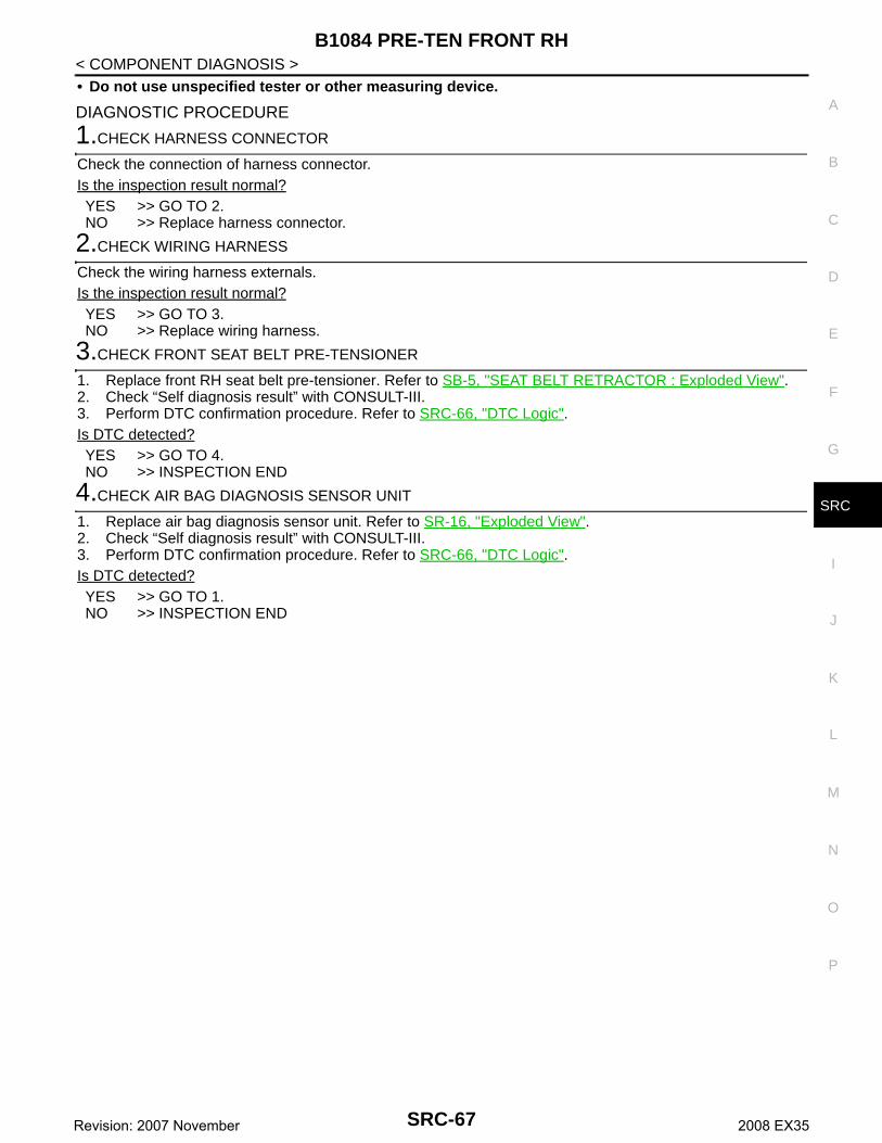
B1084 PRE-TEN FRONT RH
C
D
E
F
G
I
J
K
L
M
A
B
RC
N
O
P
< COMPONENT DIAGNOSIS >
S
• Do not use unspecified tester or other measuring device.
DIAGNOSTIC PROCEDURE
1.CHECK HARNESS CONNECTOR
Check the connection of harness connector.Is the inspection result normal?YES >> GO TO 2.NO >> Replace harness connector.
2.CHECK WIRING HARNESS
Check the wiring harness externals.Is the inspection result normal?YES >> GO TO 3. NO >> Replace wiring harness.
3.CHECK FRONT SEAT BELT PRE-TENSIONER
1. Replace front RH seat belt pre-tensioner. Refer to SB-5, "SEAT BELT RETRACTOR : Exploded View".2. Check “Self diagnosis result” with CONSULT-III.3. Perform DTC confirmation procedure. Refer to SRC-66, "DTC Logic".Is DTC detected?YES >> GO TO 4. NO >> INSPECTION END
4.CHECK AIR BAG DIAGNOSIS SENSOR UNIT
1. Replace air bag diagnosis sensor unit. Refer to SR-16, "Exploded View".2. Check “Self diagnosis result” with CONSULT-III.3. Perform DTC confirmation procedure. Refer to SRC-66, "DTC Logic".Is DTC detected?YES >> GO TO 1. NO >> INSPECTION END
SRC-67Revision: 2007 November 2008 EX35
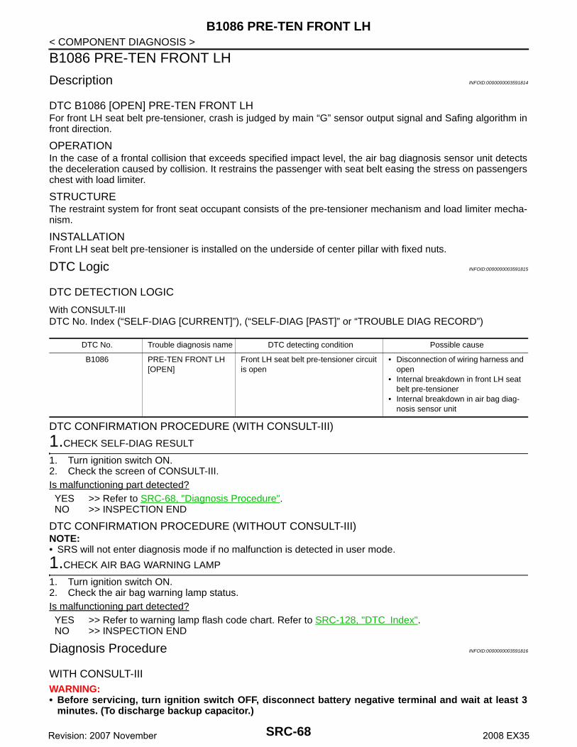
B1086 PRE-TEN FRONT LH
< COMPONENT DIAGNOSIS >B1086 PRE-TEN FRONT LH
Description INFOID:0000000003591814
DTC B1086 [OPEN] PRE-TEN FRONT LHFor front LH seat belt pre-tensioner, crash is judged by main “G” sensor output signal and Safing algorithm infront direction.
OPERATIONIn the case of a frontal collision that exceeds specified impact level, the air bag diagnosis sensor unit detectsthe deceleration caused by collision. It restrains the passenger with seat belt easing the stress on passengerschest with load limiter.
STRUCTUREThe restraint system for front seat occupant consists of the pre-tensioner mechanism and load limiter mecha-nism.
INSTALLATIONFront LH seat belt pre-tensioner is installed on the underside of center pillar with fixed nuts.
DTC Logic INFOID:0000000003591815
DTC DETECTION LOGIC
With CONSULT-IIIDTC No. Index (“SELF-DIAG [CURRENT]”), (“SELF-DIAG [PAST]” or “TROUBLE DIAG RECORD”)
DTC CONFIRMATION PROCEDURE (WITH CONSULT-III)
1.CHECK SELF-DIAG RESULT
1. Turn ignition switch ON.2. Check the screen of CONSULT-III.Is malfunctioning part detected?YES >> Refer to SRC-68, "Diagnosis Procedure".NO >> INSPECTION END
DTC CONFIRMATION PROCEDURE (WITHOUT CONSULT-III)NOTE:• SRS will not enter diagnosis mode if no malfunction is detected in user mode.
1.CHECK AIR BAG WARNING LAMP
1. Turn ignition switch ON.2. Check the air bag warning lamp status.Is malfunctioning part detected?YES >> Refer to warning lamp flash code chart. Refer to SRC-128, "DTC Index".NO >> INSPECTION END
Diagnosis Procedure INFOID:0000000003591816
WITH CONSULT-IIIWARNING:• Before servicing, turn ignition switch OFF, disconnect battery negative terminal and wait at least 3
minutes. (To discharge backup capacitor.)
DTC No. Trouble diagnosis name DTC detecting condition Possible cause
B1086 PRE-TEN FRONT LH [OPEN]
Front LH seat belt pre-tensioner circuit is open
• Disconnection of wiring harness and open
• Internal breakdown in front LH seat belt pre-tensioner
• Internal breakdown in air bag diag-nosis sensor unit
SRC-68Revision: 2007 November 2008 EX35

B1086 PRE-TEN FRONT LH
C
D
E
F
G
I
J
K
L
M
A
B
RC
N
O
P
< COMPONENT DIAGNOSIS >
S
• Do not use unspecified tester or other measuring device.
DIAGNOSTIC PROCEDURE
1.CHECK HARNESS CONNECTOR
Check the connection of harness connector.Is the inspection result normal?YES >> GO TO 2.NO >> Replace harness connector.
2.CHECK WIRING HARNESS
Check the wiring harness externals.Is the inspection result normal?YES >> GO TO 3. NO >> Replace wiring harness.
3.CHECK FRONT SEAT BELT PRE-TENSIONER
1. Replace front LH seat belt pre-tensioner. Refer to SB-5, "SEAT BELT RETRACTOR : Exploded View".2. Check “Self diagnosis result” with CONSULT-III.3. Perform DTC confirmation procedure. Refer to SRC-68, "DTC Logic".Is DTC detected?YES >> GO TO 1. NO >> INSPECTION END
4.CHECK AIR BAG DIAGNOSIS SENSOR UNIT
1. Replace air bag diagnosis sensor unit. Refer to SR-16, "Exploded View".2. Check “Self diagnosis result” with CONSULT-III.3. Perform DTC confirmation procedure. Refer to SRC-68, "DTC Logic".Is DTC detected?YES >> GO TO 1. NO >> INSPECTION END
SRC-69Revision: 2007 November 2008 EX35

B1087 PRE-TEN FRONT LH
< COMPONENT DIAGNOSIS >B1087 PRE-TEN FRONT LH
Description INFOID:0000000003591817
DTC B1087 [VB-SHORT] PRE-TEN FRONT LHFor front LH seat belt pre-tensioner, crash is judged by main “G” sensor output signal and Safing algorithm infront direction.
OPERATIONIn the case of a frontal collision that exceeds specified impact level, the air bag diagnosis sensor unit detectsthe deceleration caused by collision. It restrains the passenger with seat belt easing the stress on passengerschest with load limiter.
STRUCTUREThe restraint system for front seat occupant consists of the pre-tensioner mechanism and load limiter mecha-nism.
INSTALLATIONFront LH seat belt pre-tensioner is installed on the underside of center pillar with fixed nuts.
DTC Logic INFOID:0000000003591818
DTC DETECTION LOGIC
With CONSULT-IIIDTC No. Index (“SELF-DIAG [CURRENT]”), (“SELF-DIAG [PAST]” or “TROUBLE DIAG RECORD”)
DTC CONFIRMATION PROCEDURE (WITH CONSULT-III)
1.CHECK SELF-DIAG RESULT
1. Turn ignition switch ON.2. Check the screen of CONSULT-III.Is malfunctioning part detected?YES >> Refer to SRC-70, "Diagnosis Procedure".NO >> INSPECTION END
DTC CONFIRMATION PROCEDURE (WITHOUT CONSULT-III)NOTE:• SRS will not enter diagnosis mode if no malfunction is detected in user mode.
1.CHECK AIR BAG WARNING LAMP
1. Turn ignition switch ON.2. Check the air bag warning lamp status.Is malfunctioning part detected?YES >> Refer to warning lamp flash code chart. Refer to SRC-128, "DTC Index".NO >> INSPECTION END
Diagnosis Procedure INFOID:0000000003758575
WITH CONSULT-IIIWARNING:• Before servicing, turn ignition switch OFF, disconnect battery negative terminal and wait at least 3
minutes. (To discharge backup capacitor.)
DTC No. Trouble diagnosis name DTC detecting condition Possible cause
B1087 PRE-TEN FRONT LH[VB-SHORT]
Front LH seat belt pre-tensioner circuit is shorted to some power supply circuit
• Disconnection of wiring harness and short
• Internal breakdown in front LH seat belt pre-tensioner
• Internal breakdown in air bag diag-nosis sensor unit
SRC-70Revision: 2007 November 2008 EX35

B1087 PRE-TEN FRONT LH
C
D
E
F
G
I
J
K
L
M
A
B
RC
N
O
P
< COMPONENT DIAGNOSIS >
S
• Do not use unspecified tester or other measuring device.
DIAGNOSTIC PROCEDURE
1.CHECK HARNESS CONNECTOR
Check the connection of harness connector.Is the inspection result normal?YES >> GO TO 2.NO >> Replace harness connector.
2.CHECK WIRING HARNESS
Check the wiring harness externals.Is the inspection result normal?YES >> GO TO 3. NO >> Replace wiring harness.
3.CHECK FRONT SEAT BELT PRE-TENSIONER
1. Replace front LH seat belt pre-tensioner. Refer to SB-5, "SEAT BELT RETRACTOR : Exploded View".2. Check “Self diagnosis result” with CONSULT-III.3. Perform DTC confirmation procedure. Refer to SRC-70, "DTC Logic".Is DTC detected?YES >> GO TO 4. NO >> INSPECTION END
4.CHECK AIR BAG DIAGNOSIS SENSOR UNIT
1. Replace air bag diagnosis sensor unit. Refer to SR-16, "Exploded View".2. Check “Self diagnosis result” with CONSULT-III.3. Perform DTC confirmation procedure. Refer to SRC-70, "DTC Logic".Is DTC detected?YES >> GO TO 1. NO >> INSPECTION END
SRC-71Revision: 2007 November 2008 EX35

B1088 PRE-TEN FRONT LH
< COMPONENT DIAGNOSIS >B1088 PRE-TEN FRONT LH
Description INFOID:0000000003591820
DTC B1088 [GND-SHORT] PRE-TEN FRONT LHFor front LH seat belt pre-tensioner, crash is judged by main “G” sensor output signal and Safing algorithm infront direction.
OPERATIONIn the case of a frontal collision that exceeds specified impact level, the air bag diagnosis sensor unit detectsthe deceleration caused by collision. It restrains the passenger with seat belt easing the stress on passengerschest with load limiter.
STRUCTUREThe restraint system for front seat occupant consists of the pre-tensioner mechanism and load limiter mecha-nism.
INSTALLATIONFront LH seat belt pre-tensioner is installed on the underside of center pillar with fixed nuts.
DTC Logic INFOID:0000000003591821
DTC DETECTION LOGIC
With CONSULT-IIIDTC No. Index (“SELF-DIAG [CURRENT]”), (“SELF-DIAG [PAST]” or “TROUBLE DIAG RECORD”)
DTC CONFIRMATION PROCEDURE (WITH CONSULT-III)
1.CHECK SELF-DIAG RESULT
1. Turn ignition switch ON.2. Check the screen of CONSULT-III.Is malfunctioning part detected?YES >> Refer to SRC-72, "Diagnosis Procedure".NO >> INSPECTION END
DTC CONFIRMATION PROCEDURE (WITHOUT CONSULT-III)NOTE:• SRS will not enter diagnosis mode if no malfunction is detected in user mode.
1.CHECK AIR BAG WARNING LAMP
1. Turn ignition switch ON.2. Check the air bag warning lamp status.Is malfunctioning part detected?YES >> Refer to warning lamp flash code chart. Refer to SRC-128, "DTC Index".NO >> INSPECTION END
Diagnosis Procedure INFOID:0000000003758584
WITH CONSULT-IIIWARNING:• Before servicing, turn ignition switch OFF, disconnect battery negative terminal and wait at least 3
minutes. (To discharge backup capacitor.)
DTC No. Trouble diagnosis name DTC detecting condition Possible cause
B1088 PRE-TEN FRONT LH [GND-SHORT]
Front LH seat belt pre-tensioner circuit is shorted to ground
• Disconnection of wiring harness and short
• Internal breakdown in front LH seat belt pre-tensioner
• Internal breakdown in air bag diag-nosis sensor unit
SRC-72Revision: 2007 November 2008 EX35

B1088 PRE-TEN FRONT LH
C
D
E
F
G
I
J
K
L
M
A
B
RC
N
O
P
< COMPONENT DIAGNOSIS >
S
• Do not use unspecified tester or other measuring device.
DIAGNOSTIC PROCEDURE
1.CHECK HARNESS CONNECTOR
Check the connection of harness connector.Is the inspection result normal?YES >> GO TO 2.NO >> Replace harness connector.
2.CHECK WIRING HARNESS
Check the wiring harness externals.Is the inspection result normal?YES >> GO TO 3. NO >> Replace wiring harness.
3.CHECK FRONT SEAT BELT PRE-TENSIONER
1. Replace front LH seat belt pre-tensioner. Refer to SB-5, "SEAT BELT RETRACTOR : Exploded View".2. Check “Self diagnosis result” with CONSULT-III.3. Perform DTC confirmation procedure. Refer to SRC-72, "DTC Logic".Is DTC detected?YES >> GO TO 4. NO >> INSPECTION END
4.CHECK AIR BAG DIAGNOSIS SENSOR UNIT
1. Replace air bag diagnosis sensor unit. Refer to SR-16, "Exploded View".2. Check “Self diagnosis result” with CONSULT-III.3. Perform DTC confirmation procedure. Refer to SRC-72, "DTC Logic".Is DTC detected?YES >> GO TO 1. NO >> INSPECTION END
SRC-73Revision: 2007 November 2008 EX35
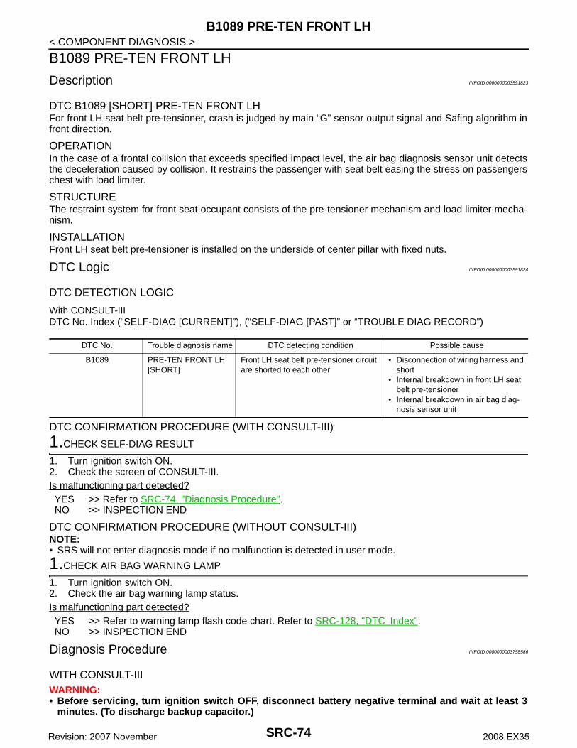
B1089 PRE-TEN FRONT LH
< COMPONENT DIAGNOSIS >B1089 PRE-TEN FRONT LH
Description INFOID:0000000003591823
DTC B1089 [SHORT] PRE-TEN FRONT LHFor front LH seat belt pre-tensioner, crash is judged by main “G” sensor output signal and Safing algorithm infront direction.
OPERATIONIn the case of a frontal collision that exceeds specified impact level, the air bag diagnosis sensor unit detectsthe deceleration caused by collision. It restrains the passenger with seat belt easing the stress on passengerschest with load limiter.
STRUCTUREThe restraint system for front seat occupant consists of the pre-tensioner mechanism and load limiter mecha-nism.
INSTALLATIONFront LH seat belt pre-tensioner is installed on the underside of center pillar with fixed nuts.
DTC Logic INFOID:0000000003591824
DTC DETECTION LOGIC
With CONSULT-IIIDTC No. Index (“SELF-DIAG [CURRENT]”), (“SELF-DIAG [PAST]” or “TROUBLE DIAG RECORD”)
DTC CONFIRMATION PROCEDURE (WITH CONSULT-III)
1.CHECK SELF-DIAG RESULT
1. Turn ignition switch ON.2. Check the screen of CONSULT-III.Is malfunctioning part detected?YES >> Refer to SRC-74, "Diagnosis Procedure".NO >> INSPECTION END
DTC CONFIRMATION PROCEDURE (WITHOUT CONSULT-III)NOTE:• SRS will not enter diagnosis mode if no malfunction is detected in user mode.
1.CHECK AIR BAG WARNING LAMP
1. Turn ignition switch ON.2. Check the air bag warning lamp status.Is malfunctioning part detected?YES >> Refer to warning lamp flash code chart. Refer to SRC-128, "DTC Index".NO >> INSPECTION END
Diagnosis Procedure INFOID:0000000003758586
WITH CONSULT-IIIWARNING:• Before servicing, turn ignition switch OFF, disconnect battery negative terminal and wait at least 3
minutes. (To discharge backup capacitor.)
DTC No. Trouble diagnosis name DTC detecting condition Possible cause
B1089 PRE-TEN FRONT LH [SHORT]
Front LH seat belt pre-tensioner circuit are shorted to each other
• Disconnection of wiring harness and short
• Internal breakdown in front LH seat belt pre-tensioner
• Internal breakdown in air bag diag-nosis sensor unit
SRC-74Revision: 2007 November 2008 EX35

B1089 PRE-TEN FRONT LH
C
D
E
F
G
I
J
K
L
M
A
B
RC
N
O
P
< COMPONENT DIAGNOSIS >
S
• Do not use unspecified tester or other measuring device.
DIAGNOSTIC PROCEDURE
1.CHECK HARNESS CONNECTOR
Check the connection of harness connector.Is the inspection result normal?YES >> GO TO 2.NO >> Replace harness connector.
2.CHECK WIRING HARNESS
Check the wiring harness externals.Is the inspection result normal?YES >> GO TO 3. NO >> Replace wiring harness.
3.CHECK FRONT SEAT BELT PRE-TENSIONER
1. Replace front LH seat belt pre-tensioner. Refer to SB-5, "SEAT BELT RETRACTOR : Exploded View".2. Check “Self diagnosis result” with CONSULT-III.3. Perform DTC confirmation procedure. Refer to SRC-74, "DTC Logic".Is DTC detected?YES >> GO TO 4. NO >> INSPECTION END
4.CHECK AIR BAG DIAGNOSIS SENSOR UNIT
1. Replace air bag diagnosis sensor unit. Refer to SR-16, "Exploded View".2. Check “Self diagnosis result” with CONSULT-III.3. Perform DTC confirmation procedure. Refer to SRC-74, "DTC Logic".Is DTC detected?YES >> GO TO 1. NO >> INSPECTION END
SRC-75Revision: 2007 November 2008 EX35
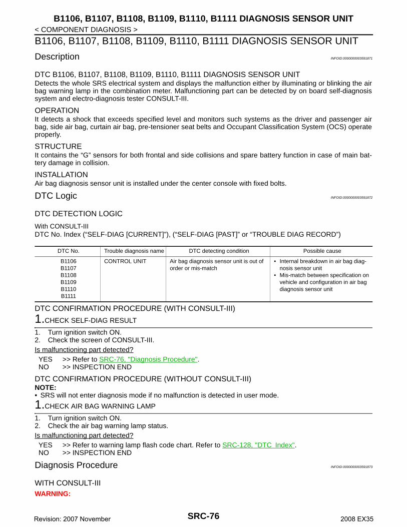
B1106, B1107, B1108, B1109, B1110, B1111 DIAGNOSIS SENSOR UNIT
< COMPONENT DIAGNOSIS >B1106, B1107, B1108, B1109, B1110, B1111 DIAGNOSIS SENSOR UNIT
Description INFOID:0000000003591871
DTC B1106, B1107, B1108, B1109, B1110, B1111 DIAGNOSIS SENSOR UNITDetects the whole SRS electrical system and displays the malfunction either by illuminating or blinking the airbag warning lamp in the combination meter. Malfunctioning part can be detected by on board self-diagnosissystem and electro-diagnosis tester CONSULT-III.
OPERATIONIt detects a shock that exceeds specified level and monitors such systems as the driver and passenger airbag, side air bag, curtain air bag, pre-tensioner seat belts and Occupant Classification System (OCS) operateproperly.
STRUCTUREIt contains the “G” sensors for both frontal and side collisions and spare battery function in case of main bat-tery damage in collision.
INSTALLATIONAir bag diagnosis sensor unit is installed under the center console with fixed bolts.
DTC Logic INFOID:0000000003591872
DTC DETECTION LOGIC
With CONSULT-IIIDTC No. Index (“SELF-DIAG [CURRENT]”), (“SELF-DIAG [PAST]” or “TROUBLE DIAG RECORD”)
DTC CONFIRMATION PROCEDURE (WITH CONSULT-III)
1.CHECK SELF-DIAG RESULT
1. Turn ignition switch ON.2. Check the screen of CONSULT-III.Is malfunctioning part detected?YES >> Refer to SRC-76, "Diagnosis Procedure".NO >> INSPECTION END
DTC CONFIRMATION PROCEDURE (WITHOUT CONSULT-III)NOTE:• SRS will not enter diagnosis mode if no malfunction is detected in user mode.
1.CHECK AIR BAG WARNING LAMP
1. Turn ignition switch ON.2. Check the air bag warning lamp status.Is malfunctioning part detected?YES >> Refer to warning lamp flash code chart. Refer to SRC-128, "DTC Index".NO >> INSPECTION END
Diagnosis Procedure INFOID:0000000003591873
WITH CONSULT-IIIWARNING:
DTC No. Trouble diagnosis name DTC detecting condition Possible cause
B1106B1107B1108B1109B1110B1111
CONTROL UNIT Air bag diagnosis sensor unit is out of order or mis-match
• Internal breakdown in air bag diag-nosis sensor unit
• Mis-match between specification on vehicle and configuration in air bag diagnosis sensor unit
SRC-76Revision: 2007 November 2008 EX35

B1106, B1107, B1108, B1109, B1110, B1111 DIAGNOSIS SENSOR UNIT
C
D
E
F
G
I
J
K
L
M
A
B
RC
N
O
P
< COMPONENT DIAGNOSIS >
S
• Before servicing, turn ignition switch OFF, disconnect battery negative terminal and wait at least 3minutes. (To discharge backup capacitor.)
• Do not use unspecified tester or other measuring device.
DIAGNOSTIC PROCEDURE
1.CHECK HARNESS CONNECTOR
Check the connection of harness connector.Is the inspection result normal?YES >> GO TO 2.NO >> Replace harness connectors.
2.CHECK WIRING HARNESS
Check the wiring harness externals.Is the inspection result normal?YES >> GO TO 3.NO >> Replace wiring harness.
3.CHECK AIR BAG DIAGNOSIS SENSOR UNIT
1. Replace air bag diagnosis sensor unit. Refer to SR-16, "Exploded View".2. Check “Self diagnosis result” with CONSULT-III.3. Perform DTC confirmation procedure. Refer to SRC-76, "DTC Logic".Is DTC detected?YES >> GO TO 1. NO >> INSPECTION END
SRC-77Revision: 2007 November 2008 EX35
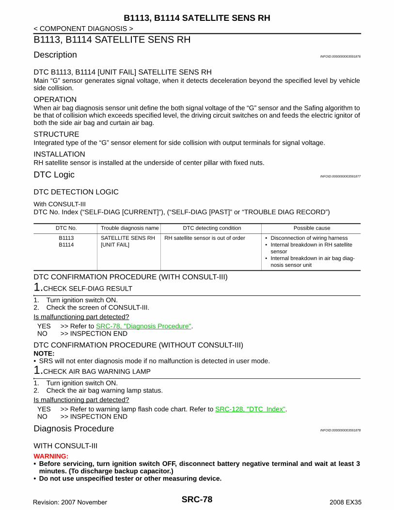
B1113, B1114 SATELLITE SENS RH
< COMPONENT DIAGNOSIS >B1113, B1114 SATELLITE SENS RH
Description INFOID:0000000003591876
DTC B1113, B1114 [UNIT FAIL] SATELLITE SENS RHMain “G” sensor generates signal voltage, when it detects deceleration beyond the specified level by vehicleside collision.
OPERATIONWhen air bag diagnosis sensor unit define the both signal voltage of the “G” sensor and the Safing algorithm tobe that of collision which exceeds specified level, the driving circuit switches on and feeds the electric ignitor ofboth the side air bag and curtain air bag.
STRUCTUREIntegrated type of the “G” sensor element for side collision with output terminals for signal voltage.
INSTALLATIONRH satellite sensor is installed at the underside of center pillar with fixed nuts.
DTC Logic INFOID:0000000003591877
DTC DETECTION LOGIC
With CONSULT-IIIDTC No. Index (“SELF-DIAG [CURRENT]”), (“SELF-DIAG [PAST]” or “TROUBLE DIAG RECORD”)
DTC CONFIRMATION PROCEDURE (WITH CONSULT-III)
1.CHECK SELF-DIAG RESULT
1. Turn ignition switch ON.2. Check the screen of CONSULT-III.Is malfunctioning part detected?YES >> Refer to SRC-78, "Diagnosis Procedure".NO >> INSPECTION END
DTC CONFIRMATION PROCEDURE (WITHOUT CONSULT-III)NOTE:• SRS will not enter diagnosis mode if no malfunction is detected in user mode.
1.CHECK AIR BAG WARNING LAMP
1. Turn ignition switch ON.2. Check the air bag warning lamp status.Is malfunctioning part detected?YES >> Refer to warning lamp flash code chart. Refer to SRC-128, "DTC Index".NO >> INSPECTION END
Diagnosis Procedure INFOID:0000000003591878
WITH CONSULT-IIIWARNING:• Before servicing, turn ignition switch OFF, disconnect battery negative terminal and wait at least 3
minutes. (To discharge backup capacitor.)• Do not use unspecified tester or other measuring device.
DTC No. Trouble diagnosis name DTC detecting condition Possible cause
B1113B1114
SATELLITE SENS RH [UNIT FAIL]
RH satellite sensor is out of order • Disconnection of wiring harness• Internal breakdown in RH satellite
sensor• Internal breakdown in air bag diag-
nosis sensor unit
SRC-78Revision: 2007 November 2008 EX35

B1113, B1114 SATELLITE SENS RH
C
D
E
F
G
I
J
K
L
M
A
B
RC
N
O
P
< COMPONENT DIAGNOSIS >
S
DIAGNOSTIC PROCEDURE
1.CHECK HARNESS CONNECTOR
Check the connection of harness connector.Is the inspection result normal?YES >> GO TO 2.NO >> Replace harness connector.
2.CHECK WIRING HARNESS
Check the wiring harness externals.Is the inspection result normal?YES >> GO TO 3. NO >> Replace wiring harness.
3.CHECK SATELLITE SENSOR
1. Replace RH satellite sensor. Refer to SR-14, "Exploded View".2. Check “Self diagnosis result” with CONSULT-III.3. Perform DTC confirmation procedure. Refer to SRC-78, "DTC Logic".Is DTC detected?YES >> GO TO 4. NO >> INSPECTION END
4.CHECK AIR BAG DIAGNOSIS SENSOR UNIT
1. Replace air bag diagnosis sensor unit. Refer to SR-16, "Exploded View".2. Check “Self diagnosis result” with CONSULT-III.3. Perform DTC confirmation procedure. Refer to SRC-78, "DTC Logic".Is DTC detected?YES >> GO TO 1. NO >> INSPECTION END
SRC-79Revision: 2007 November 2008 EX35

B1115, B1116 SATELLITE SENS RH
< COMPONENT DIAGNOSIS >B1115, B1116 SATELLITE SENS RH
Description INFOID:0000000003591880
DTC B1115, B1116 [COMM FAIL] SATELLITE SENS RHMain “G” sensor generates signal voltage, when it detects deceleration beyond the specified level by vehicleside collision.
OPERATIONWhen air bag diagnosis sensor unit defines both signal voltage of the “G” sensor and the Safing algorithm tobe that of collision which exceeds specified level, the driving circuit switches on and feeds the electric ignitor ofboth the front side air bag and side curtain air bag.
STRUCTUREIntegrated type of the “G” sensor element for side collision with output terminals for signal voltage.
INSTALLATIONRH satellite sensor is installed at the underside of center pillar with fixed nuts.
DTC Logic INFOID:0000000003591881
DTC DETECTION LOGIC
With CONSULT-IIIDTC No. Index (“SELF-DIAG [CURRENT]”), (“SELF-DIAG [PAST]” or “TROUBLE DIAG RECORD”)
DTC CONFIRMATION PROCEDURE (WITH CONSULT-III)
1.CHECK SELF-DIAG RESULT
1. Turn ignition switch ON.2. Check the screen of CONSULT-III.Is malfunctioning part detected?YES >> Refer to SRC-80, "Diagnosis Procedure".NO >> INSPECTION END
DTC CONFIRMATION PROCEDURE (WITHOUT CONSULT-III)NOTE:• SRS will not enter diagnosis mode if no malfunction is detected in user mode.
1.CHECK AIR BAG WARNING LAMP
1. Turn ignition switch ON.2. Check the air bag warning lamp status.Is malfunctioning part detected?YES >> Refer to warning lamp flash code chart. Refer to SRC-128, "DTC Index".NO >> INSPECTION END
Diagnosis Procedure INFOID:0000000003591882
WITH CONSULT-IIIWARNING:• Before servicing, turn ignition switch OFF, disconnect battery negative terminal and wait at least 3
minutes. (To discharge backup capacitor.)• Do not use unspecified tester or other measuring device.
DTC No. Trouble diagnosis name DTC detecting condition Possible cause
B1115B1116
SATELLITE SENS RH [COMM FAIL][UNMATCH]
RH satellite sensor is out of order • Disconnection of wiring harness• Internal breakdown in RH satellite
sensor• Internal breakdown in air bag diag-
nosis sensor unit
SRC-80Revision: 2007 November 2008 EX35

B1115, B1116 SATELLITE SENS RH
C
D
E
F
G
I
J
K
L
M
A
B
RC
N
O
P
< COMPONENT DIAGNOSIS >
S
DIAGNOSTIC PROCEDURE
1.CHECK HARNESS CONNECTOR
Check the connection of harness connector.Is the inspection result normal?YES >> GO TO 2.NO >> Replace harness connector.
2.CHECK WIRING HARNESS
Check the wiring harness externals.Is the inspection result normal?YES >> GO TO 3. NO >> Replace wiring harness.
3.CHECK SATELLITE SENSOR
1. Replace RH satellite sensor. Refer to SR-14, "Exploded View".2. Check “Self diagnosis result” with CONSULT-III.3. Perform DTC confirmation procedure. Refer to SRC-80, "DTC Logic".Is DTC detected?YES >> GO TO 4. NO >> INSPECTION END
4.CHECK AIR BAG DIAGNOSIS SENSOR UNIT
1. Replace air bag diagnosis sensor unit. Refer to SR-16, "Exploded View".2. Check “Self diagnosis result” with CONSULT-III.3. Perform DTC confirmation procedure. Refer to SRC-80, "DTC Logic".Is DTC detected?YES >> GO TO 1. NO >> INSPECTION END
SRC-81Revision: 2007 November 2008 EX35

B1118, B1119 SATELLITE SENS LH
< COMPONENT DIAGNOSIS >B1118, B1119 SATELLITE SENS LH
Description INFOID:0000000003591883
DTC B1118, B1119 [UNIT FAIL] SATELLITE SENS LHMain “G” sensor generates signal voltage, when it detects deceleration beyond the specified level by vehicleside collision.
OPERATIONWhen air bag diagnosis sensor unit defines both signal voltage of the “G” sensor and the Safing algorithm tobe that of collision which exceeds specified level, the driving circuit switches on and feeds the electric ignitor ofboth the front side air bag and side curtain air bag.
STRUCTUREIntegrated type of the “G” sensor element for side collision with output terminals for signal voltage.
INSTALLATIONLH satellite sensor is installed at the underside of center pillar with fixed nuts.
DTC Logic INFOID:0000000003591884
DTC DETECTION LOGIC
With CONSULT-IIIDTC No. Index (“SELF-DIAG [CURRENT]”), (“SELF-DIAG [PAST]” or “TROUBLE DIAG RECORD”)
DTC CONFIRMATION PROCEDURE (WITH CONSULT-III)
1.CHECK SELF-DIAG RESULT
1. Turn ignition switch ON.2. Check the screen of CONSULT-III.Is malfunctioning part detected?YES >> Refer to SRC-82, "Diagnosis Procedure".NO >> INSPECTION END
DTC CONFIRMATION PROCEDURE (WITHOUT CONSULT-III)NOTE:• SRS will not enter diagnosis mode if no malfunction is detected in user mode.
1.CHECK AIR BAG WARNING LAMP
1. Turn ignition switch ON.2. Check the air bag warning lamp status.Is malfunctioning part detected?YES >> Refer to warning lamp flash code chart. Refer to SRC-128, "DTC Index".NO >> INSPECTION END
Diagnosis Procedure INFOID:0000000003591885
WITH CONSULT-IIIWARNING:• Before servicing, turn ignition switch OFF, disconnect battery negative terminal and wait at least 3
minutes. (To discharge backup capacitor.)• Do not use unspecified tester or other measuring device.
DTC No. Trouble diagnosis name DTC detecting condition Possible cause
B1118B1119
SATELLITE SENS LH[UNIT FAIL]
LH satellite sensor is out of order • Disconnection of wiring harness• Internal breakdown in LH satellite
sensor• Internal breakdown in air bag diag-
nosis sensor unit
SRC-82Revision: 2007 November 2008 EX35

B1118, B1119 SATELLITE SENS LH
C
D
E
F
G
I
J
K
L
M
A
B
RC
N
O
P
< COMPONENT DIAGNOSIS >
S
DIAGNOSTIC PROCEDURE
1.CHECK HARNESS CONNECTOR
Check the connection of harness connector.Is the inspection result normal?YES >> GO TO 2.NO >> Replace harness connector.
2.CHECK WIRING HARNESS
Check the wiring harness externals.Is the inspection result normal?YES >> GO TO 3. NO >> Replace wiring harness.
3.CHECK SATELLITE SENSOR
1. Replace LH satellite sensor. Refer to SR-14, "Exploded View".2. Check “Self diagnosis result” with CONSULT-III.3. Perform DTC confirmation procedure. Refer to Is DTC detected?YES >> GO TO 4. NO >> INSPECTION END
4.CHECK AIR BAG DIAGNOSIS SENSOR UNIT
1. Replace air bag diagnosis sensor unit. Refer to SR-16, "Exploded View".2. Check “Self diagnosis result” with CONSULT-III.3. Perform DTC confirmation procedure. Refer to SRC-82, "DTC Logic".Is DTC detected?YES >> GO TO 1. NO >> INSPECTION END
SRC-83Revision: 2007 November 2008 EX35
B1120, B1121 SATELLITE SENS LH
< COMPONENT DIAGNOSIS >B1120, B1121 SATELLITE SENS LH
Description INFOID:0000000003591886
DTC B1120, B1121 [COMM FAIL] SATELLITE SENS LHMain “G” sensor generates signal voltage, when it detects deceleration beyond the specified level by vehicleside collision.
OPERATIONWhen air bag diagnosis sensor unit defines both signal voltage of the “G” sensor and the Safing algorithm tobe that of collision which exceeds specified level, the driving circuit switches on and feeds the electric ignitor ofboth the front side air bag and side curtain air bag.
STRUCTUREIntegrated type of the “G” sensor element for side collision with output terminals for signal voltage.
INSTALLATIONLH satellite sensor is installed at the underside of center pillar with fixed nuts.
DTC Logic INFOID:0000000003591887
DTC DETECTION LOGIC
With CONSULT-IIIDTC No. Index (“SELF-DIAG [CURRENT]”), (“SELF-DIAG [PAST]” or “TROUBLE DIAG RECORD”)
DTC CONFIRMATION PROCEDURE (WITH CONSULT-III)
1.CHECK SELF-DIAG RESULT
1. Turn ignition switch ON.2. Check the screen of CONSULT-III.Is malfunctioning part detected?YES >> Refer to SRC-84, "Diagnosis Procedure".NO >> INSPECTION END
DTC CONFIRMATION PROCEDURE (WITHOUT CONSULT-III)NOTE:• SRS will not enter diagnosis mode if no malfunction is detected in user mode.
1.CHECK AIR BAG WARNING LAMP
1. Turn ignition switch ON.2. Check the air bag warning lamp status.Is malfunctioning part detected?YES >> Refer to warning lamp flash code chart. Refer to SRC-128, "DTC Index".NO >> INSPECTION END
Diagnosis Procedure INFOID:0000000003591888
WITH CONSULT-IIIWARNING:• Before servicing, turn ignition switch OFF, disconnect battery negative terminal and wait at least 3
minutes. (To discharge backup capacitor.)• Do not use unspecified tester or other measuring device.
DTC No. Trouble diagnosis name DTC detecting condition Possible cause
B1120B1121
SATELLITE SENS LH [COMM FAIL][UNMATCH]
LH satellite sensor is out of order • Disconnection of wiring harness• Internal breakdown in LH satellite
sensor• Internal breakdown in air bag diag-
nosis sensor unit
SRC-84Revision: 2007 November 2008 EX35

B1120, B1121 SATELLITE SENS LH
C
D
E
F
G
I
J
K
L
M
A
B
RC
N
O
P
< COMPONENT DIAGNOSIS >
S
DIAGNOSTIC PROCEDURE
1.CHECK HARNESS CONNECTOR
Check the connection of harness connector.Is the inspection result normal?YES >> GO TO 2.NO >> Replace harness connector.
2.CHECK WIRING HARNESS
Check the wiring harness externals.Is the inspection result normal?YES >> GO TO 3. NO >> Replace wiring harness.
3.CHECK SATELLITE SENSOR
1. Replace LH satellite sensor. Refer to SR-14, "Exploded View".2. Check “Self diagnosis result” with CONSULT-III.3. Perform DTC confirmation procedure. Refer to SRC-84, "DTC Logic".Is DTC detected?YES >> GO TO 4. NO >> INSPECTION END
4.CHECK AIR BAG DIAGNOSIS SENSOR UNIT
1. Replace air bag diagnosis sensor unit. Refer to SR-16, "Exploded View".2. Check “Self diagnosis result” with CONSULT-III.3. Perform DTC confirmation procedure. Refer to SRC-84, "DTC Logic".Is DTC detected?YES >> GO TO 1. NO >> INSPECTION END
SRC-85Revision: 2007 November 2008 EX35

B1122, B1123, B1124, B1125, B1126, B1127 DIAGNOSIS SENSOR UNIT
< COMPONENT DIAGNOSIS >B1122, B1123, B1124, B1125, B1126, B1127 DIAGNOSIS SENSOR UNIT
Description INFOID:0000000003595949
DTC B1122, B1123, B1124, B1125, B1126, B1127 DIAGNOSIS SENSOR UNITDetects the whole SRS electrical system and displays the malfunction either by illuminating or blinking the airbag warning lamp in the combination meter. Malfunctioning part can be detected by on board self-diagnosissystem and electro-diagnosis tester CONSULT-III.
OPERATIONIt detects a shock that exceeds specified level and monitors such systems as the driver and passenger airbag, front side air bag, side curtain air bag and pre-tensioner seat belts operate properly.
STRUCTUREIt contains the “G” sensors for both frontal and side collisions and spare battery function in case of main bat-tery damage in collision.
INSTALLATIONAir bag diagnosis sensor unit is installed under the center console with fixed bolts.
DTC Logic INFOID:0000000003595950
DTC DETECTION LOGIC
With CONSULT-IIIDTC No. Index (“SELF-DIAG [CURRENT]”), (“SELF-DIAG [PAST]” or “TROUBLE DIAG RECORD”)
DTC CONFIRMATION PROCEDURE (WITH CONSULT-III)
1.CHECK SELF-DIAG RESULT
1. Turn ignition switch ON.2. Check the screen of CONSULT-III.Is malfunctioning part detected?YES >> Refer to SRC-86, "Diagnosis Procedure".NO >> INSPECTION END
DTC CONFIRMATION PROCEDURE (WITHOUT CONSULT-III)NOTE:• SRS will not enter diagnosis mode if no malfunction is detected in user mode.
1.CHECK AIR BAG WARNING LAMP
1. Turn ignition switch ON.2. Check the air bag warning lamp status.Is malfunctioning part detected?YES >> Refer to warning lamp flash code chart. Refer to SRC-128, "DTC Index".NO >> INSPECTION END
Diagnosis Procedure INFOID:0000000003595951
WITH CONSULT-IIIWARNING:• Before servicing, turn ignition switch OFF, disconnect battery negative terminal and wait at least 3
minutes. (To discharge backup capacitor.)
DTC No. Trouble diagnosis name DTC detecting condition Possible cause
B1122B1123B1124B1125B1126B1127
CONTROL UNIT Air bag diagnosis sensor unit is out of order or mis-match
• Internal breakdown in air bag diag-nosis sensor unit
• Mis-match between specification on vehicle and configuration in air bag diagnosis sensor unit
SRC-86Revision: 2007 November 2008 EX35

B1122, B1123, B1124, B1125, B1126, B1127 DIAGNOSIS SENSOR UNIT
C
D
E
F
G
I
J
K
L
M
A
B
RC
N
O
P
< COMPONENT DIAGNOSIS >
S
• Do not use unspecified tester or other measuring device.
DIAGNOSTIC PROCEDURE
1.CHECK HARNESS CONNECTOR
Check the connection of harness connector.Is the inspection result normal?YES >> GO TO 2.NO >> Replace harness connectors.
2.CHECK WIRING HARNESS
Check the wiring harness externals.Is the inspection result normal?YES >> GO TO 3.NO >> Replace wiring harness.
3.CHECK AIR BAG DIAGNOSIS SENSOR UNIT
1. Replace air bag diagnosis sensor unit. Refer to SR-16, "Exploded View".2. Check “Self diagnosis result” with CONSULT-III.3. Perform DTC confirmation procedure. Refer to SRC-86, "DTC Logic".Is DTC detected?YES >> GO TO 1. NO >> INSPECTION END
SRC-87Revision: 2007 November 2008 EX35

B1129 SIDE MODULE RH
< COMPONENT DIAGNOSIS >B1129 SIDE MODULE RH
Description INFOID:0000000003595952
DTC B1129 [OPEN] SIDE MODULE RHFor front RH side air bag module, crash is judged by main “G” sensor output signal (left side:LH satellite sen-sor, right side:RH satellite sensor) and Safing algorithm (in air bag diagnosis sensor unit).
OPERATIONIn the case of a collision whose acceleration exceeds the specified level, the ignition materials are ignited byelectric ignition system. The system burns and introduces the chemical reaction of gas generating materials togenerate hot gases that flow into the air bag through a filter and expand the bag.
STRUCTUREFront RH side air bag module mainly consists of air bag and inflator which inflates air bag.
INSTALLATIONFront RH side air bag module is installed on the side of front seat back with fixed nuts.
DTC Logic INFOID:0000000003595953
DTC DETECTION LOGIC
With CONSULT-IIIDTC No. Index (“SELF-DIAG [CURRENT]”), (“SELF-DIAG [PAST]” or “TROUBLE DIAG RECORD”)
DTC CONFIRMATION PROCEDURE (WITH CONSULT-III)
1.CHECK SELF-DIAG RESULT
1. Turn ignition switch ON.2. Check the screen of CONSULT-III.Is malfunctioning part detected?YES >> Refer to SRC-88, "Diagnosis Procedure".NO >> INSPECTION END
DTC CONFIRMATION PROCEDURE (WITHOUT CONSULT-III)NOTE:• SRS will not enter diagnosis mode if no malfunction is detected in user mode.
1.CHECK AIR BAG WARNING LAMP
1. Turn ignition switch ON.2. Check the air bag warning lamp status.Is malfunctioning part detected?YES >> Refer to warning lamp flash code chart. Refer to SRC-128, "DTC Index".NO >> INSPECTION END
Diagnosis Procedure INFOID:0000000003595954
WITH CONSULT-IIIWARNING:• Before servicing, turn ignition switch OFF, disconnect battery negative terminal and wait at least 3
minutes. (To discharge backup capacitor.)• Do not use unspecified tester or other measuring device.
DTC No. Trouble diagnosis name DTC detecting condition Possible cause
B1129 SIDE MODULE RH[OPEN]
Front RH side air bag module circuit is open
• Disconnection of wiring harness and open
• Internal breakdown in front RH side air bag module
• Internal breakdown in air bag diag-nosis sensor unit
SRC-88Revision: 2007 November 2008 EX35

B1129 SIDE MODULE RH
C
D
E
F
G
I
J
K
L
M
A
B
RC
N
O
P
< COMPONENT DIAGNOSIS >
S
DIAGNOSTIC PROCEDURE
1.CHECK HARNESS CONNECTOR
Check the connection of harness connector.Is the inspection result normal?YES >> GO TO 2.NO >> Replace harness connector.
2.CHECK WIRING HARNESS
Check the wiring harness externals.Is the inspection result normal?YES >> GO TO 3. NO >> Replace wiring harness.
3.CHECK FRONT SIDE AIR BAG MODULE
1. Replace front RH side air bag module. Refer to SR-10, "Exploded View".2. Check “Self diagnosis result” with CONSULT-III.3. Perform DTC confirmation procedure. Refer to SRC-88, "DTC Logic".Is DTC detected?YES >> GO TO 4. NO >> INSPECTION END
4.CHECK AIR BAG DIAGNOSIS SENSOR UNIT
1. Replace air bag diagnosis sensor unit. Refer to SR-16, "Exploded View".2. Check “Self diagnosis result” with CONSULT-III.3. Perform DTC confirmation procedure. Refer to SRC-88, "DTC Logic".Is DTC detected?YES >> GO TO 1. NO >> INSPECTION END
SRC-89Revision: 2007 November 2008 EX35

B1130 SIDE MODULE RH
< COMPONENT DIAGNOSIS >B1130 SIDE MODULE RH
Description INFOID:0000000003595955
DTC B1130 [VB-SHORT] SIDE MODULE RHFor front RH side air bag module, crash is judged by main “G” sensor output signal (left side: LH satellite sen-sor, right side: RH satellite sensor) and Safing algorithm (in air bag diagnosis sensor unit).
OPERATIONIn the case of a collision whose acceleration exceeds the specified level, the ignition materials are ignited byelectric ignition system. The system burns and introduces the chemical reaction of gas generating materials togenerate hot gases that flow into the air bag through a filter and expand the bag.
STRUCTUREFront RH side air bag module mainly consists of air bag and inflator which inflates air bag.
INSTALLATIONFront RH side air bag module is installed on the side of front seatback with fixed nuts.
DTC Logic INFOID:0000000003595956
DTC DETECTION LOGIC
With CONSULT-IIIDTC No. Index (“SELF-DIAG [CURRENT]”), (“SELF-DIAG [PAST]” or “TROUBLE DIAG RECORD”)
DTC CONFIRMATION PROCEDURE (WITH CONSULT-III)
1.CHECK SELF-DIAG RESULT
1. Turn ignition switch ON.2. Check the screen of CONSULT-III.Is malfunctioning part detected?YES >> Refer to SRC-90, "Diagnosis Procedure".NO >> INSPECTION END
DTC CONFIRMATION PROCEDURE (WITHOUT CONSULT-III)NOTE:• SRS will not enter diagnosis mode if no malfunction is detected in user mode.
1.CHECK AIR BAG WARNING LAMP
1. Turn ignition switch ON.2. Check the air bag warning lamp status.Is malfunctioning part detected?YES >> Refer to warning lamp flash code chart. Refer to SRC-128, "DTC Index".NO >> INSPECTION END
Diagnosis Procedure INFOID:0000000003595957
WITH CONSULT-IIIWARNING:• Before servicing, turn ignition switch OFF, disconnect battery negative terminal and wait at least 3
minutes. (To discharge backup capacitor.)• Do not use unspecified tester or other measuring device.
DTC No. Trouble diagnosis name DTC detecting condition Possible cause
B1130 SIDE MODULE RH [VB-SHORT]
Front RH side air bag module circuit is shorted to some power supply circuit
• Disconnection of wiring harness and short
• Internal breakdown in front RH side air bag module
• Internal breakdown in air bag diag-nosis sensor unit
SRC-90Revision: 2007 November 2008 EX35
B1130 SIDE MODULE RH
C
D
E
F
G
I
J
K
L
M
A
B
RC
N
O
P
< COMPONENT DIAGNOSIS >
S
DIAGNOSTIC PROCEDURE
1.CHECK HARNESS CONNECTOR
Check the connection of harness connector.Is the inspection result normal?YES >> GO TO 2.NO >> Replace harness connector.
2.CHECK WIRING HARNESS
Check the wiring harness externals.Is the inspection result normal?YES >> GO TO 3. NO >> Replace wiring harness.
3.CHECK FRONT SIDE AIR BAG MODULE
1. Replace front RH side air bag module. Refer to SR-10, "Exploded View".2. Check “Self diagnosis result” with CONSULT-III.3. Perform DTC confirmation procedure. Refer to SRC-90, "DTC Logic".Is DTC detected?YES >> GO TO 4. NO >> INSPECTION END
4.CHECK AIR BAG DIAGNOSIS SENSOR UNIT
1. Replace air bag diagnosis sensor unit. Refer to SR-16, "Exploded View".2. Check “Self diagnosis result” with CONSULT-III.3. Perform DTC confirmation procedure. Refer to SRC-90, "DTC Logic".Is DTC detected?YES >> GO TO 1. NO >> INSPECTION END
SRC-91Revision: 2007 November 2008 EX35

B1131 SIDE MODULE RH
< COMPONENT DIAGNOSIS >B1131 SIDE MODULE RH
Description INFOID:0000000003595958
DTC B1131 [GND-SHORT] SIDE MODULE RHFor front RH side air bag module, crash is judged by main “G” sensor output signal (left side:LH satellite sen-sor, right side:RH satellite sensor) and Safing algorithm (in air bag diagnosis sensor unit).
OPERATIONIn the case of a collision whose acceleration exceeds the specified level, the ignition materials are ignited byelectric ignition system. The system burns and introduces the chemical reaction of gas generating materials togenerate hot gases that flow into the air bag through a filter and expand the bag.
STRUCTUREFront RH side air bag module mainly consists of air bag and inflator which inflates air bag.
INSTALLATIONFront RH side air bag module is installed on the side of front seatback with fixed nuts.
DTC Logic INFOID:0000000003595959
DTC DETECTION LOGIC
With CONSULT-IIIDTC No. Index (“SELF-DIAG [CURRENT]”), (“SELF-DIAG [PAST]” or “TROUBLE DIAG RECORD”)
DTC CONFIRMATION PROCEDURE (WITH CONSULT-III)
1.CHECK SELF-DIAG RESULT
1. Turn ignition switch ON.2. Check the screen of CONSULT-III.Is malfunctioning part detected?YES >> Refer to SRC-92, "Diagnosis Procedure".NO >> INSPECTION END
DTC CONFIRMATION PROCEDURE (WITHOUT CONSULT-III)NOTE:• SRS will not enter diagnosis mode if no malfunction is detected in user mode.
1.CHECK AIR BAG WARNING LAMP
1. Turn ignition switch ON.2. Check the air bag warning lamp status.Is malfunctioning part detected?YES >> Refer to warning lamp flash code chart. Refer to SRC-128, "DTC Index".NO >> INSPECTION END
Diagnosis Procedure INFOID:0000000003595960
WITH CONSULT-IIIWARNING:• Before servicing, turn ignition switch OFF, disconnect battery negative terminal and wait at least 3
minutes. (To discharge backup capacitor.)• Do not use unspecified tester or other measuring device.
DTC No. Trouble diagnosis name DTC detecting condition Possible cause
B1131 SIDE MODULE RH [GND-SHORT]
Front RH side air bag module circuit is shorted to ground
• Disconnection of wiring harness and short
• Internal breakdown in front RH side air bag module
• Internal breakdown in air bag diag-nosis sensor unit
SRC-92Revision: 2007 November 2008 EX35

B1131 SIDE MODULE RH
C
D
E
F
G
I
J
K
L
M
A
B
RC
N
O
P
< COMPONENT DIAGNOSIS >
S
DIAGNOSTIC PROCEDURE
1.CHECK HARNESS CONNECTOR
Check the connection of harness connector.Is the inspection result normal?YES >> GO TO 2.NO >> Replace harness connector.
2.CHECK WIRING HARNESS
Check the wiring harness externals.Is the inspection result normal?YES >> GO TO 3. NO >> Replace wiring harness.
3.CHECK FRONT SIDE AIR BAG MODULE
1. Replace front RH side air bag module. Refer to SR-10, "Exploded View".2. Check “Self diagnosis result” with CONSULT-III.3. Perform DTC confirmation procedure. Refer to SRC-92, "DTC Logic".Is DTC detected?YES >> GO TO 4. NO >> INSPECTION END
4.CHECK AIR BAG DIAGNOSIS SENSOR UNIT
1. Replace air bag diagnosis sensor unit. Refer to SR-16, "Exploded View".2. Check “Self diagnosis result” with CONSULT-III.3. Perform DTC confirmation procedure. Refer to SRC-92, "DTC Logic".Is DTC detected?YES >> GO TO 1. NO >> INSPECTION END
SRC-93Revision: 2007 November 2008 EX35

B1132 SIDE MODULE RH
< COMPONENT DIAGNOSIS >B1132 SIDE MODULE RH
Description INFOID:0000000003595961
DTC B1132 [SHORT] SIDE MODULE RHFor front RH side air bag module, crash is judged by main “G” sensor output signal (left side:LH satellite sen-sor, right side:RH satellite sensor) and Safing algorithm (in air bag diagnosis sensor unit).
OPERATIONIn the case of a collision whose acceleration exceeds the specified level, the ignition materials are ignited byelectric ignition system. The system burns and introduces the chemical reaction of gas generating materials togenerate hot gases that flow into the air bag through a filter and expand the bag.
STRUCTUREFront RH side air bag module mainly consists of air bag and inflator which inflates air bag.
INSTALLATIONFront RH side air bag module is installed on the side of front seatback with fixed nuts.
DTC Logic INFOID:0000000003595962
DTC DETECTION LOGIC
With CONSULT-IIIDTC No. Index (“SELF-DIAG [CURRENT]”), (“SELF-DIAG [PAST]” or “TROUBLE DIAG RECORD”)
DTC CONFIRMATION PROCEDURE (WITH CONSULT-III)
1.CHECK SELF-DIAG RESULT
1. Turn ignition switch ON.2. Check the screen of CONSULT-III.Is malfunctioning part detected?YES >> Refer to SRC-94, "Diagnosis Procedure".NO >> INSPECTION END
DTC CONFIRMATION PROCEDURE (WITHOUT CONSULT-III)NOTE:• SRS will not enter diagnosis mode if no malfunction is detected in user mode.
1.CHECK AIR BAG WARNING LAMP
1. Turn ignition switch ON.2. Check the air bag warning lamp status.Is malfunctioning part detected?YES >> Refer to warning lamp flash code chart. Refer to SRC-128, "DTC Index".NO >> INSPECTION END
Diagnosis Procedure INFOID:0000000003595963
WITH CONSULT-IIIWARNING:• Before servicing, turn ignition switch OFF, disconnect battery negative terminal and wait at least 3
minutes. (To discharge backup capacitor.)• Do not use unspecified tester or other measuring device.
DTC No. Trouble diagnosis name DTC detecting condition Possible cause
B1132 SIDE MODULE RH [SHORT]
Front RH side air bag module circuit are shorted to each other
• Disconnection of wiring harness and short
• Internal breakdown in front RH side air bag module
• Internal breakdown in air bag diag-nosis sensor unit
SRC-94Revision: 2007 November 2008 EX35

B1132 SIDE MODULE RH
C
D
E
F
G
I
J
K
L
M
A
B
RC
N
O
P
< COMPONENT DIAGNOSIS >
S
DIAGNOSTIC PROCEDURE
1.CHECK HARNESS CONNECTOR
Check the connection of harness connector.Is the inspection result normal?YES >> GO TO 2.NO >> Replace harness connector.
2.CHECK WIRING HARNESS
Check the wiring harness externals.Is the inspection result normal?YES >> GO TO 3. NO >> Replace wiring harness.
3.CHECK FRONT SIDE AIR BAG MODULE
1. Replace front RH side air bag module. Refer to SR-10, "Exploded View".2. Check “Self diagnosis result” with CONSULT-III.3. Perform DTC confirmation procedure. Refer to SRC-94, "DTC Logic".Is DTC detected?YES >> GO TO 4. NO >> INSPECTION END
4.CHECK AIR BAG DIAGNOSIS SENSOR UNIT
1. Replace air bag diagnosis sensor unit. Refer to SR-16, "Exploded View".2. Check “Self diagnosis result” with CONSULT-III.3. Perform DTC confirmation procedure. Refer to SRC-94, "DTC Logic".Is DTC detected?YES >> GO TO 1. NO >> INSPECTION END
SRC-95Revision: 2007 November 2008 EX35
B1134 SIDE MODULE LH
< COMPONENT DIAGNOSIS >B1134 SIDE MODULE LH
Description INFOID:0000000003595964
DTC B1134 [OPEN] SIDE MODULE LHFor front LH side air bag module, crash is judged by main “G” sensor output signal (left side:LH satellite sen-sor, right side:RH satellite sensor) and Safing algorithm (in air bag diagnosis sensor unit).
OPERATIONIn the case of a collision whose acceleration exceeds the specified level, the ignition materials are ignited byelectric ignition system. The system burns and introduces the chemical reaction of gas generating materials togenerate hot gases that flow into the air bag through a filter and expand the bag.
STRUCTUREFront LH side air bag module mainly consists of air bag and inflator which inflates air bag.
INSTALLATIONFront LH side air bag module is installed on the side of front seatback with fixed nuts.
DTC Logic INFOID:0000000003595965
DTC DETECTION LOGIC
With CONSULT-IIIDTC No. Index (“SELF-DIAG [CURRENT]”), (“SELF-DIAG [PAST]” or “TROUBLE DIAG RECORD”)
DTC CONFIRMATION PROCEDURE (WITH CONSULT-III)
1.CHECK SELF-DIAG RESULT
1. Turn ignition switch ON.2. Check the screen of CONSULT-III.Is malfunctioning part detected?YES >> Refer to SRC-96, "Diagnosis Procedure".NO >> INSPECTION END
DTC CONFIRMATION PROCEDURE (WITHOUT CONSULT-III)NOTE:• SRS will not enter diagnosis mode if no malfunction is detected in user mode.
1.CHECK AIR BAG WARNING LAMP
1. Turn ignition switch ON.2. Check the air bag warning lamp status.Is malfunctioning part detected?YES >> Refer to warning lamp flash code chart. Refer to SRC-128, "DTC Index".NO >> INSPECTION END
Diagnosis Procedure INFOID:0000000003595966
WITH CONSULT-IIIWARNING:• Before servicing, turn ignition switch OFF, disconnect battery negative terminal and wait at least 3
minutes. (To discharge backup capacitor.)• Do not use unspecified tester or other measuring device.
DTC No. Trouble diagnosis name DTC detecting condition Possible cause
B1134 SIDE MODULE LH [OPEN]
Front LH side air bag module circuit is open
• Disconnection of wiring harness and open
• Internal breakdown in front LH side air bag module
• Internal breakdown in air bag diag-nosis sensor unit
SRC-96Revision: 2007 November 2008 EX35

B1134 SIDE MODULE LH
C
D
E
F
G
I
J
K
L
M
A
B
RC
N
O
P
< COMPONENT DIAGNOSIS >
S
DIAGNOSTIC PROCEDURE
1.CHECK HARNESS CONNECTOR
Check the connection of harness connector.Is the inspection result normal?YES >> GO TO 2.NO >> Replace harness connector.
2.CHECK WIRING HARNESS
Check the wiring harness externals.Is the inspection result normal?YES >> GO TO 3. NO >> Replace wiring harness.
3.CHECK FRONT SIDE AIR BAG MODULE
1. Replace front LH side air bag module. Refer to SR-10, "Exploded View".2. Check “Self diagnosis result” with CONSULT-III.3. Perform DTC confirmation procedure. Refer to SRC-96, "DTC Logic".Is DTC detected?YES >> GO TO 4. NO >> INSPECTION END
4.CHECK AIR BAG DIAGNOSIS SENSOR UNIT
1. Replace air bag diagnosis sensor unit. Refer to SR-16, "Exploded View".2. Check “Self diagnosis result” with CONSULT-III.3. Perform DTC confirmation procedure. Refer to SRC-96, "DTC Logic".Is DTC detected?YES >> GO TO 1. NO >> INSPECTION END
SRC-97Revision: 2007 November 2008 EX35

B1135 SIDE MODULE LH
< COMPONENT DIAGNOSIS >B1135 SIDE MODULE LH
Description INFOID:0000000003595967
DTC B1135 [VB-SHORT] SIDE MODULE LHFor front LH side air bag module, crash is judged by main “G” sensor output signal (left side:LH satellite sen-sor, right side:RH satellite sensor) and Safing algorithm (in air bag diagnosis sensor unit).
OPERATIONIn the case of a collision whose acceleration exceeds the specified level, the ignition materials are ignited byelectric ignition system. The system burns and introduces the chemical reaction of gas generating materials togenerate hot gases that flow into the air bag through a filter and expand the bag.
STRUCTUREFront LH side air bag module mainly consists of air bag and inflator which inflates air bag.
INSTALLATIONFront LH side air bag module is installed on the side of front seatback with fixed nuts.
DTC Logic INFOID:0000000003595968
DTC DETECTION LOGIC
With CONSULT-IIIDTC No. Index (“SELF-DIAG [CURRENT]”), (“SELF-DIAG [PAST]” or “TROUBLE DIAG RECORD”)
DTC CONFIRMATION PROCEDURE (WITH CONSULT-III)
1.CHECK SELF-DIAG RESULT
1. Turn ignition switch ON.2. Check the screen of CONSULT-III.Is malfunctioning part detected?YES >> Refer to SRC-98, "Diagnosis Procedure".NO >> INSPECTION END
DTC CONFIRMATION PROCEDURE (WITHOUT CONSULT-III)NOTE:• SRS will not enter diagnosis mode if no malfunction is detected in user mode.
1.CHECK AIR BAG WARNING LAMP
1. Turn ignition switch ON.2. Check the air bag warning lamp status.Is malfunctioning part detected?YES >> Refer to warning lamp flash code chart. Refer to SRC-128, "DTC Index".NO >> INSPECTION END
Diagnosis Procedure INFOID:0000000003595969
WITH CONSULT-IIIWARNING:• Before servicing, turn ignition switch OFF, disconnect battery negative terminal and wait at least 3
minutes. (To discharge backup capacitor.)• Do not use unspecified tester or other measuring device.
DTC No. Trouble diagnosis name DTC detecting condition Possible cause
B1135 SIDE MODULE LH [VB-SHORT]
Front LH side air bag module circuit is shorted to some power supply circuit
• Disconnection of wiring harness and short
• Internal breakdown in front LH side air bag module
• Internal breakdown in air bag diag-nosis sensor unit
SRC-98Revision: 2007 November 2008 EX35

B1135 SIDE MODULE LH
C
D
E
F
G
I
J
K
L
M
A
B
RC
N
O
P
< COMPONENT DIAGNOSIS >
S
DIAGNOSTIC PROCEDURE
1.CHECK HARNESS CONNECTOR
Check the connection of harness connector.Is the inspection result normal?YES >> GO TO 2.NO >> Replace harness connector.
2.CHECK WIRING HARNESS
Check the wiring harness externals.Is the inspection result normal?YES >> GO TO 3. NO >> Replace wiring harness.
3.CHECK FRONT SIDE AIR BAG MODULE
1. Replace front LH side air bag module. Refer to SR-10, "Exploded View".2. Check “Self diagnosis result” with CONSULT-III.3. Perform DTC confirmation procedure. Refer to SRC-98, "DTC Logic".Is DTC detected?YES >> GO TO 4. NO >> INSPECTION END
4.CHECK AIR BAG DIAGNOSIS SENSOR UNIT
1. Replace air bag diagnosis sensor unit. Refer to SR-16, "Exploded View".2. Check “Self diagnosis result” with CONSULT-III.3. Perform DTC confirmation procedure. Refer to SRC-98, "DTC Logic".Is DTC detected?YES >> GO TO 1. NO >> INSPECTION END
SRC-99Revision: 2007 November 2008 EX35

B1136 SIDE MODULE LH
< COMPONENT DIAGNOSIS >B1136 SIDE MODULE LH
Description INFOID:0000000003595970
DTC B1136 [GND-SHORT] SIDE MODULE LHFor front LH side air bag module, crash is judged by main “G” sensor output signal (left side:LH satellite sen-sor, right side:RH satellite sensor) and Safing algorithm (in air bag diagnosis sensor unit).
OPERATIONIn the case of a collision whose acceleration exceeds the specified level, the ignition materials are ignited byelectric ignition system. The system burns and introduces the chemical reaction of gas generating materials togenerate hot gases that flow into the air bag through a filter and expand the bag.
STRUCTUREFront LH side air bag module mainly consists of air bag and inflator which inflates air bag.
INSTALLATIONFront LH side air bag module is installed on the side of front seatback with fixed nuts.
DTC Logic INFOID:0000000003595971
DTC DETECTION LOGIC
With CONSULT-IIIDTC No. Index (“SELF-DIAG [CURRENT]”), (“SELF-DIAG [PAST]” or “TROUBLE DIAG RECORD”)
DTC CONFIRMATION PROCEDURE (WITH CONSULT-III)
1.CHECK SELF-DIAG RESULT
1. Turn ignition switch ON.2. Check the screen of CONSULT-III.Is malfunctioning part detected?YES >> Refer to SRC-100, "Diagnosis Procedure".NO >> INSPECTION END
DTC CONFIRMATION PROCEDURE (WITHOUT CONSULT-III)NOTE:• SRS will not enter diagnosis mode if no malfunction is detected in user mode.
1.CHECK AIR BAG WARNING LAMP
1. Turn ignition switch ON.2. Check the air bag warning lamp status.Is malfunctioning part detected?YES >> Refer to warning lamp flash code chart. Refer to SRC-128, "DTC Index".NO >> INSPECTION END
Diagnosis Procedure INFOID:0000000003595972
WITH CONSULT-IIIWARNING:• Before servicing, turn ignition switch OFF, disconnect battery negative terminal and wait at least 3
minutes. (To discharge backup capacitor.)• Do not use unspecified tester or other measuring device.
DTC No. Trouble diagnosis name DTC detecting condition Possible cause
B1136 SIDE MODULE LH [GND-SHORT]
Front LH side air bag module circuit is shorted to ground
• Disconnection of wiring harness and short
• Internal breakdown in front LH side air bag module
• Internal breakdown in air bag diag-nosis sensor unit
SRC-100Revision: 2007 November 2008 EX35
B1136 SIDE MODULE LH
C
D
E
F
G
I
J
K
L
M
A
B
RC
N
O
P
< COMPONENT DIAGNOSIS >
S
DIAGNOSTIC PROCEDURE
1.CHECK HARNESS CONNECTOR
Check the connection of harness connector.Is the inspection result normal?YES >> GO TO 2.NO >> Replace harness connector.
2.CHECK WIRING HARNESS
Check the wiring harness externals.Is the inspection result normal?YES >> GO TO 3. NO >> Replace wiring harness.
3.CHECK FRONT SIDE AIR BAG MODULE
1. Replace front LH side air bag module. Refer to SR-10, "Exploded View".2. Check “Self diagnosis result” with CONSULT-III.3. Perform DTC confirmation procedure. Refer to SRC-100, "DTC Logic".Is DTC detected?YES >> GO TO 4. NO >> INSPECTION END
4.CHECK AIR BAG DIAGNOSIS SENSOR UNIT
1. Replace air bag diagnosis sensor unit. Refer to SR-16, "Exploded View".2. Check “Self diagnosis result” with CONSULT-III.3. Perform DTC confirmation procedure. Refer to SRC-100, "DTC Logic".Is DTC detected?YES >> GO TO 1. NO >> INSPECTION END
SRC-101Revision: 2007 November 2008 EX35
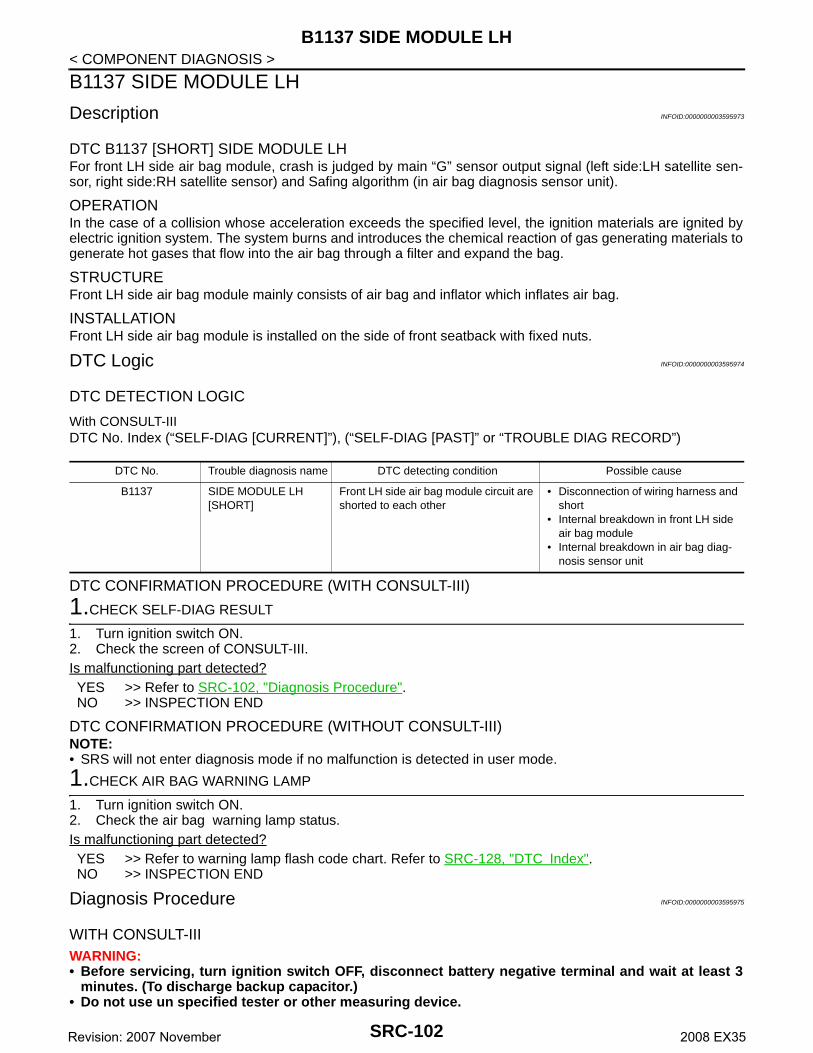
B1137 SIDE MODULE LH
< COMPONENT DIAGNOSIS >B1137 SIDE MODULE LH
Description INFOID:0000000003595973
DTC B1137 [SHORT] SIDE MODULE LHFor front LH side air bag module, crash is judged by main “G” sensor output signal (left side:LH satellite sen-sor, right side:RH satellite sensor) and Safing algorithm (in air bag diagnosis sensor unit).
OPERATIONIn the case of a collision whose acceleration exceeds the specified level, the ignition materials are ignited byelectric ignition system. The system burns and introduces the chemical reaction of gas generating materials togenerate hot gases that flow into the air bag through a filter and expand the bag.
STRUCTUREFront LH side air bag module mainly consists of air bag and inflator which inflates air bag.
INSTALLATIONFront LH side air bag module is installed on the side of front seatback with fixed nuts.
DTC Logic INFOID:0000000003595974
DTC DETECTION LOGIC
With CONSULT-IIIDTC No. Index (“SELF-DIAG [CURRENT]”), (“SELF-DIAG [PAST]” or “TROUBLE DIAG RECORD”)
DTC CONFIRMATION PROCEDURE (WITH CONSULT-III)
1.CHECK SELF-DIAG RESULT
1. Turn ignition switch ON.2. Check the screen of CONSULT-III.Is malfunctioning part detected?YES >> Refer to SRC-102, "Diagnosis Procedure".NO >> INSPECTION END
DTC CONFIRMATION PROCEDURE (WITHOUT CONSULT-III)NOTE:• SRS will not enter diagnosis mode if no malfunction is detected in user mode.
1.CHECK AIR BAG WARNING LAMP
1. Turn ignition switch ON.2. Check the air bag warning lamp status.Is malfunctioning part detected?YES >> Refer to warning lamp flash code chart. Refer to SRC-128, "DTC Index".NO >> INSPECTION END
Diagnosis Procedure INFOID:0000000003595975
WITH CONSULT-IIIWARNING:• Before servicing, turn ignition switch OFF, disconnect battery negative terminal and wait at least 3
minutes. (To discharge backup capacitor.)• Do not use un specified tester or other measuring device.
DTC No. Trouble diagnosis name DTC detecting condition Possible cause
B1137 SIDE MODULE LH [SHORT]
Front LH side air bag module circuit are shorted to each other
• Disconnection of wiring harness and short
• Internal breakdown in front LH side air bag module
• Internal breakdown in air bag diag-nosis sensor unit
SRC-102Revision: 2007 November 2008 EX35

B1137 SIDE MODULE LH
C
D
E
F
G
I
J
K
L
M
A
B
RC
N
O
P
< COMPONENT DIAGNOSIS >
S
DIAGNOSTIC PROCEDURE
1.CHECK HARNESS CONNECTOR
Check the connection of harness connector.Is the inspection result normal?YES >> GO TO 2.NO >> Replace harness connector.
2.CHECK WIRING HARNESS
Check the wiring harness externals.Is the inspection result normal?YES >> GO TO 3. NO >> Replace wiring harness.
3.CHECK FRONT SIDE AIR BAG MODULE
1. Replace front LH side air bag module. Refer to SR-10, "Exploded View".2. Check “Self diagnosis result” with CONSULT-III.3. Perform DTC confirmation procedure. Refer to SRC-102, "DTC Logic".Is DTC detected?YES >> GO TO 4. NO >> INSPECTION END
4.CHECK AIR BAG DIAGNOSIS SENSOR UNIT
1. Replace air bag diagnosis sensor unit. Refer to SR-16, "Exploded View".2. Check “Self diagnosis result” with CONSULT-III.3. Perform DTC confirmation procedure. Refer to SRC-102, "DTC Logic".Is DTC detected?YES >> GO TO 1. NO >> INSPECTION END
SRC-103Revision: 2007 November 2008 EX35

B1138, B1139, B1140, B1141, B1142, B1143 DIAGNOSIS SENSOR UNIT
< COMPONENT DIAGNOSIS >B1138, B1139, B1140, B1141, B1142, B1143 DIAGNOSIS SENSOR UNIT
Description INFOID:0000000003591889
DTC B1138, B1139, B1140, B1141, B1142, B1143 DIAGNOSIS SENSOR UNITDetects the whole SRS electrical system and displays the malfunction either by illuminating or blinking the airbag warning lamp in the combination meter. Malfunctioning part can be detected by on board self-diagnosissystem and electro-diagnosis tester CONSULT-III.
OPERATIONIt detects a shock that exceeds specified level and monitors such systems as the driver and passenger airbag, side air bag, curtain air bag, pre-tensioner seat belts and Occupant Classification System (OCS) operateproperly.
STRUCTUREIt contains the “G” sensors for both frontal and side collisions and spare battery function in case of main bat-tery damage in collision.
INSTALLATIONAir bag diagnosis sensor unit is installed under the center console with fixed bolts.
DTC Logic INFOID:0000000003591890
DTC DETECTION LOGIC
With CONSULT-IIIDTC No. Index (“SELF-DIAG [CURRENT]”), (“SELF-DIAG [PAST]” or “TROUBLE DIAG RECORD”)
DTC CONFIRMATION PROCEDURE (WITH CONSULT-III)
1.CHECK SELF-DIAG RESULT
1. Turn ignition switch ON.2. Check the screen of CONSULT-III.Is malfunctioning part detected?YES >> Refer to SRC-104, "Diagnosis Procedure".NO >> INSPECTION END
DTC CONFIRMATION PROCEDURE (WITHOUT CONSULT-III)NOTE:• SRS will not enter diagnosis mode if no malfunction is detected in user mode.
1.CHECK AIR BAG WARNING LAMP
1. Turn ignition switch ON.2. Check the air bag warning lamp status.Is malfunctioning part detected?YES >> Refer to warning lamp flash code chart. Refer to SRC-128, "DTC Index".NO >> INSPECTION END
Diagnosis Procedure INFOID:0000000003591891
WITH CONSULT-IIIWARNING:
DTC No. Trouble diagnosis name DTC detecting condition Possible cause
B1138B1139B1140B1141B1142B1143
CONTROL UNIT Air bag diagnosis sensor unit is out of order or mis-match
• Internal breakdown in air bag diag-nosis sensor unit
• Mis-match between specification on vehicle and configuration in air bag diagnosis sensor unit
SRC-104Revision: 2007 November 2008 EX35

B1138, B1139, B1140, B1141, B1142, B1143 DIAGNOSIS SENSOR UNIT
C
D
E
F
G
I
J
K
L
M
A
B
RC
N
O
P
< COMPONENT DIAGNOSIS >
S
• Before servicing, turn ignition switch OFF, disconnect battery negative terminal and wait at least 3minutes. (To discharge backup capacitor.)
• Do not use unspecified tester or other measuring device.
DIAGNOSTIC PROCEDURE
1.CHECK HARNESS CONNECTOR
Check the connection of harness connector.Is the inspection result normal?YES >> GO TO 2.NO >> Replace harness connectors.
2.CHECK WIRING HARNESS
Check the wiring harness externals.Is the inspection result normal?YES >> GO TO 3.NO >> Replace wiring harness.
3.CHECK AIR BAG DIAGNOSIS SENSOR UNIT
1. Replace air bag diagnosis sensor unit. Refer to SR-4, "Exploded View".2. Check “Self diagnostic result” with CONSULT-III.3. Perform DTC confirmation procedure. Refer to SRC-104, "DTC Logic".Is DTC detected?YES >> GO TO 1. NO >> INSPECTION END
SRC-105Revision: 2007 November 2008 EX35

B1145 CURTAIN MODULE RH
< COMPONENT DIAGNOSIS >B1145 CURTAIN MODULE RH
Description INFOID:0000000003591892
DTC B1145 [OPEN] CURTAIN MODULE RHFor RH side curtain air bag module, crash is judged by main “G” sensor output signal (left side:LH satellitesensor, right side:RH satellite sensor) and Safing algorithm (left and right GP in air bag diagnosis sensor unit).
OPERATIONIn case of collision whose acceleration exceeds the specified level, the ignition materials are ignited by electricignition system. The system burns and introduces the chemical reaction of gas generating materials to gener-ate hot gases that flow into the air bag through a filter and expand the bag.
STRUCTURERH side curtain air bag module mainly consists of air bag and inflator which inflates air bag.
INSTALLATIONRH side curtain air bag module is installed on the roof side with fixed bolts.
DTC Logic INFOID:0000000003591893
DTC DETECTION LOGIC
With CONSULT-IIIDTC No. Index (“SELF-DIAG [CURRENT]”), (“SELF-DIAG [PAST]” or “TROUBLE DIAG RECORD”)
DTC CONFIRMATION PROCEDURE (WITH CONSULT-III)
1.CHECK SELF-DIAG RESULT
1. Turn ignition switch ON.2. Check the screen of CONSULT-III.Is malfunctioning part detected?YES >> Refer to SRC-106, "Diagnosis Procedure".NO >> INSPECTION END
DTC CONFIRMATION PROCEDURE (WITHOUT CONSULT-III)NOTE:• SRS will not enter diagnosis mode if no malfunction is detected in user mode.
1.CHECK AIR BAG WARNING LAMP
1. Turn ignition switch ON.2. Check the air bag warning lamp status.Is malfunctioning part detected?YES >> Refer to warning lamp flash code chart. Refer to SRC-128, "DTC Index".NO >> INSPECTION END
Diagnosis Procedure INFOID:0000000003591894
WITH CONSULT-IIIWARNING:• Before servicing, turn ignition switch OFF, disconnect battery negative terminal and wait at least 3
minutes. (To discharge backup capacitor.)• Do not use unspecified tester or other measuring device.
DTC No. Trouble diagnosis name DTC detecting condition Possible cause
B1145 CURTAIN MODULE RH [OPEN]
RH side curtain air bag module circuit is open
• Disconnection of wiring harness and open
• Internal breakdown in RH side cur-tain air bag module
• Replace air bag diagnosis sensor unit
SRC-106Revision: 2007 November 2008 EX35

B1145 CURTAIN MODULE RH
C
D
E
F
G
I
J
K
L
M
A
B
RC
N
O
P
< COMPONENT DIAGNOSIS >
S
DIAGNOSTIC PROCEDURE
1.CHECK HARNESS CONNECTOR
Check the connection of harness connector.Is the inspection result normal?YES >> GO TO 2.NO >> Replace harness connector.
2.CHECK WIRING HARNESS
Check the wiring harness externals.Is the inspection result normal?YES >> GO TO 3. NO >> Replace wiring harness.
3.CHECK SIDE CURTAIN AIR BAG MODULE
1. Replace RH side curtain air bag module.2. Check “Self diagnostic result” with CONSULT-III.3. Perform DTC confirmation procedure. Refer to SRC-106, "DTC Logic".Is DTC detected?YES >> GO TO 4. NO >> INSPECTION END
4.CHECK AIR BAG DIAGNOSIS SENSOR UNIT
1. Replace air bag diagnosis sensor unit. Refer to SR-4, "Exploded View".2. Check “Self diagnostic result” with CONSULT-III.3. Perform DTC confirmation procedure. Refer to SRC-106, "DTC Logic".Is DTC detected?YES >> GO TO 1. NO >> INSPECTION END
SRC-107Revision: 2007 November 2008 EX35
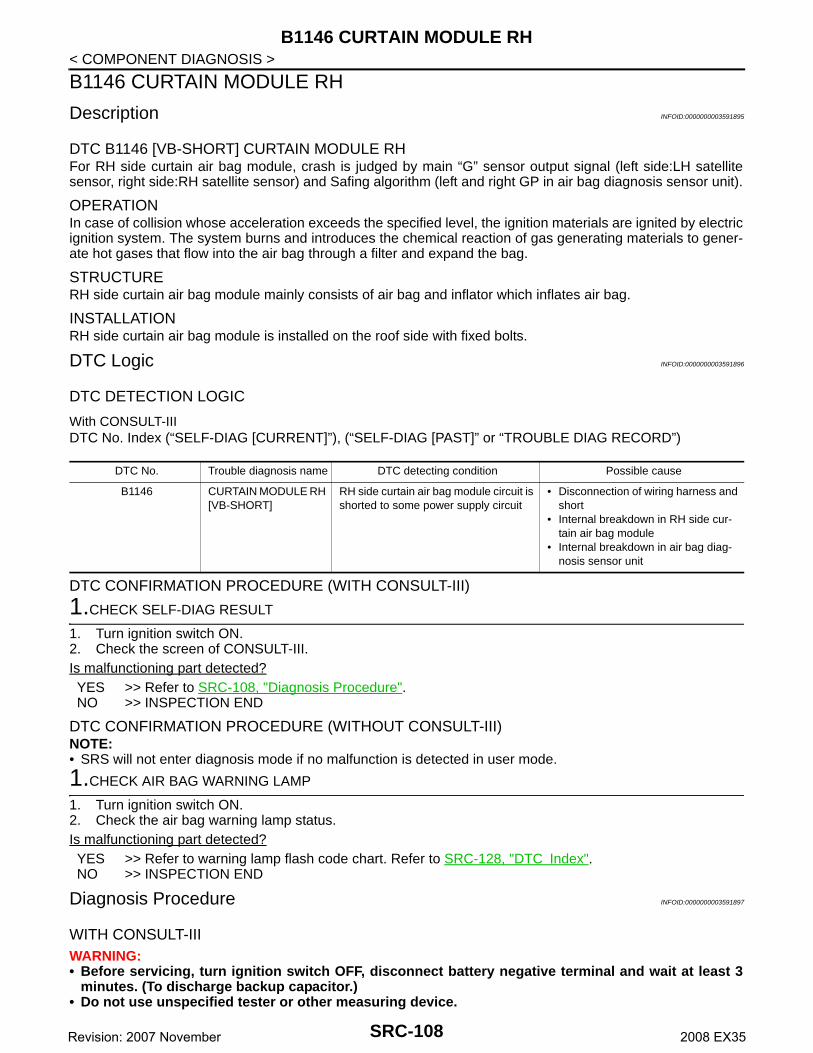
B1146 CURTAIN MODULE RH
< COMPONENT DIAGNOSIS >B1146 CURTAIN MODULE RH
Description INFOID:0000000003591895
DTC B1146 [VB-SHORT] CURTAIN MODULE RHFor RH side curtain air bag module, crash is judged by main “G” sensor output signal (left side:LH satellitesensor, right side:RH satellite sensor) and Safing algorithm (left and right GP in air bag diagnosis sensor unit).
OPERATIONIn case of collision whose acceleration exceeds the specified level, the ignition materials are ignited by electricignition system. The system burns and introduces the chemical reaction of gas generating materials to gener-ate hot gases that flow into the air bag through a filter and expand the bag.
STRUCTURERH side curtain air bag module mainly consists of air bag and inflator which inflates air bag.
INSTALLATIONRH side curtain air bag module is installed on the roof side with fixed bolts.
DTC Logic INFOID:0000000003591896
DTC DETECTION LOGIC
With CONSULT-IIIDTC No. Index (“SELF-DIAG [CURRENT]”), (“SELF-DIAG [PAST]” or “TROUBLE DIAG RECORD”)
DTC CONFIRMATION PROCEDURE (WITH CONSULT-III)
1.CHECK SELF-DIAG RESULT
1. Turn ignition switch ON.2. Check the screen of CONSULT-III.Is malfunctioning part detected?YES >> Refer to SRC-108, "Diagnosis Procedure".NO >> INSPECTION END
DTC CONFIRMATION PROCEDURE (WITHOUT CONSULT-III)NOTE:• SRS will not enter diagnosis mode if no malfunction is detected in user mode.
1.CHECK AIR BAG WARNING LAMP
1. Turn ignition switch ON.2. Check the air bag warning lamp status.Is malfunctioning part detected?YES >> Refer to warning lamp flash code chart. Refer to SRC-128, "DTC Index".NO >> INSPECTION END
Diagnosis Procedure INFOID:0000000003591897
WITH CONSULT-IIIWARNING:• Before servicing, turn ignition switch OFF, disconnect battery negative terminal and wait at least 3
minutes. (To discharge backup capacitor.)• Do not use unspecified tester or other measuring device.
DTC No. Trouble diagnosis name DTC detecting condition Possible cause
B1146 CURTAIN MODULE RH [VB-SHORT]
RH side curtain air bag module circuit is shorted to some power supply circuit
• Disconnection of wiring harness and short
• Internal breakdown in RH side cur-tain air bag module
• Internal breakdown in air bag diag-nosis sensor unit
SRC-108Revision: 2007 November 2008 EX35

B1146 CURTAIN MODULE RH
C
D
E
F
G
I
J
K
L
M
A
B
RC
N
O
P
< COMPONENT DIAGNOSIS >
S
DIAGNOSTIC PROCEDURE
1.CHECK HARNESS CONNECTOR
Check the connection of harness connector.Is the inspection result normal?YES >> GO TO 2.NO >> Replace harness connector.
2.CHECK WIRING HARNESS
Check the wiring harness externals.Is the inspection result normal?YES >> GO TO 3. NO >> Replace wiring harness.
3.CHECK SIDE CURTAIN AIR BAG MODULE
1. Replace RH side curtain air bag module.2. Check “Self diagnostic result” with CONSULT-III.3. Perform DTC confirmation procedure. Refer to SRC-108, "DTC Logic".Is DTC detected?YES >> GO TO 4. NO >> INSPECTION END
4.CHECK AIR BAG DIAGNOSIS SENSOR UNIT
1. Replace air bag diagnosis sensor unit. Refer to SR-4, "Exploded View".2. Check “Self diagnostic result” with CONSULT-III.3. Perform DTC confirmation procedure. Refer to SRC-108, "DTC Logic".Is DTC detected?YES >> GO TO 1. NO >> INSPECTION END
SRC-109Revision: 2007 November 2008 EX35

B1147 CURTAIN MODULE RH
< COMPONENT DIAGNOSIS >B1147 CURTAIN MODULE RH
Description INFOID:0000000003591898
DTC B1147 [GND-SHORT] CURTAIN MODULE RHFor RH side curtain air bag module, crash is judged by main “G” sensor output signal (left side:LH satellitesensor, right side:RH satellite sensor) and Safing algorithm (left and right GP in air bag diagnosis sensor unit).
OPERATIONIn case of collision whose acceleration exceeds the specified level, the ignition materials are ignited by electricignition system. The system burns and introduces the chemical reaction of gas generating materials to gener-ate hot gases that flow into the air bag through a filter and expand the bag.
STRUCTURERH side curtain air bag module mainly consists of air bag and inflator which inflates air bag.
INSTALLATIONRH side curtain air bag module is installed on the roof side with fixed bolts.
DTC Logic INFOID:0000000003591899
DTC DETECTION LOGIC
With CONSULT-IIIDTC No. Index (“SELF-DIAG [CURRENT]”), (“SELF-DIAG [PAST]” or “TROUBLE DIAG RECORD”)
DTC CONFIRMATION PROCEDURE (WITH CONSULT-III)
1.CHECK SELF-DIAG RESULT
1. Turn ignition switch ON.2. Check the screen of CONSULT-III.Is malfunctioning part detected?YES >> Refer to SRC-110, "Diagnosis Procedure".NO >> INSPECTION END
DTC CONFIRMATION PROCEDURE (WITHOUT CONSULT-III)NOTE:• SRS will not enter diagnosis mode if no malfunction is detected in user mode.
1.CHECK AIR BAG WARNING LAMP
1. Turn ignition switch ON.2. Check the air bag warning lamp status.Is malfunctioning part detected?YES >> Refer to warning lamp flash code chart. Refer to SRC-128, "DTC Index".NO >> INSPECTION END
Diagnosis Procedure INFOID:0000000003591900
WITH CONSULT-IIIWARNING:• Before servicing, turn ignition switch OFF, disconnect battery negative terminal and wait at least 3
minutes. (To discharge backup capacitor.)• Do not use unspecified tester or other measuring device.
DTC No. Trouble diagnosis name DTC detecting condition Possible cause
B1147 CURTAIN MODULE RH [GND-SHORT]
RH side curtain air bag module circuit is shorted to ground
• Disconnection of wiring harness and short
• Internal breakdown in RH side cur-tain air bag module
• Replace air bag diagnosis sensor unit
SRC-110Revision: 2007 November 2008 EX35
B1147 CURTAIN MODULE RH
C
D
E
F
G
I
J
K
L
M
A
B
RC
N
O
P
< COMPONENT DIAGNOSIS >
S
DIAGNOSTIC PROCEDURE
1.CHECK HARNESS CONNECTOR
Check the connection of harness connector.Is the inspection result normal?YES >> GO TO 2.NO >> Replace harness connector.
2.CHECK WIRING HARNESS
Check the wiring harness externals.Is the inspection result normal?YES >> GO TO 3. NO >> Replace wiring harness.
3.CHECK SIDE CURTAIN AIR BAG MODULE
1. Replace RH side curtain air bag module.2. Check “Self diagnostic result” with CONSULT-III.3. Perform DTC confirmation procedure. Refer to SRC-110, "DTC Logic".Is DTC detected?YES >> GO TO 4. NO >> INSPECTION END
4.CHECK AIR BAG DIAGNOSIS SENSOR UNIT
1. Replace air bag diagnosis sensor unit. Refer to SR-4, "Exploded View".2. Check “Self diagnostic result” with CONSULT-III.3. Perform DTC confirmation procedure. Refer to SRC-110, "DTC Logic".Is DTC detected?YES >> GO TO 1. NO >> INSPECTION END
SRC-111Revision: 2007 November 2008 EX35
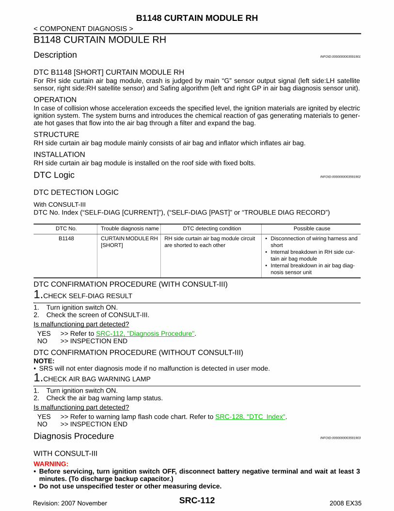
B1148 CURTAIN MODULE RH
< COMPONENT DIAGNOSIS >B1148 CURTAIN MODULE RH
Description INFOID:0000000003591901
DTC B1148 [SHORT] CURTAIN MODULE RHFor RH side curtain air bag module, crash is judged by main “G” sensor output signal (left side:LH satellitesensor, right side:RH satellite sensor) and Safing algorithm (left and right GP in air bag diagnosis sensor unit).
OPERATIONIn case of collision whose acceleration exceeds the specified level, the ignition materials are ignited by electricignition system. The system burns and introduces the chemical reaction of gas generating materials to gener-ate hot gases that flow into the air bag through a filter and expand the bag.
STRUCTURERH side curtain air bag module mainly consists of air bag and inflator which inflates air bag.
INSTALLATIONRH side curtain air bag module is installed on the roof side with fixed bolts.
DTC Logic INFOID:0000000003591902
DTC DETECTION LOGIC
With CONSULT-IIIDTC No. Index (“SELF-DIAG [CURRENT]”), (“SELF-DIAG [PAST]” or “TROUBLE DIAG RECORD”)
DTC CONFIRMATION PROCEDURE (WITH CONSULT-III)
1.CHECK SELF-DIAG RESULT
1. Turn ignition switch ON.2. Check the screen of CONSULT-III.Is malfunctioning part detected?YES >> Refer to SRC-112, "Diagnosis Procedure".NO >> INSPECTION END
DTC CONFIRMATION PROCEDURE (WITHOUT CONSULT-III)NOTE:• SRS will not enter diagnosis mode if no malfunction is detected in user mode.
1.CHECK AIR BAG WARNING LAMP
1. Turn ignition switch ON.2. Check the air bag warning lamp status.Is malfunctioning part detected?YES >> Refer to warning lamp flash code chart. Refer to SRC-128, "DTC Index".NO >> INSPECTION END
Diagnosis Procedure INFOID:0000000003591903
WITH CONSULT-IIIWARNING:• Before servicing, turn ignition switch OFF, disconnect battery negative terminal and wait at least 3
minutes. (To discharge backup capacitor.)• Do not use unspecified tester or other measuring device.
DTC No. Trouble diagnosis name DTC detecting condition Possible cause
B1148 CURTAIN MODULE RH [SHORT]
RH side curtain air bag module circuit are shorted to each other
• Disconnection of wiring harness and short
• Internal breakdown in RH side cur-tain air bag module
• Internal breakdown in air bag diag-nosis sensor unit
SRC-112Revision: 2007 November 2008 EX35

B1148 CURTAIN MODULE RH
C
D
E
F
G
I
J
K
L
M
A
B
RC
N
O
P
< COMPONENT DIAGNOSIS >
S
DIAGNOSTIC PROCEDURE
1.CHECK HARNESS CONNECTOR
Check the connection of harness connector.Is the inspection result normal?YES >> GO TO 2.NO >> Replace harness connector.
2.CHECK WIRING HARNESS
Check the wiring harness externals.Is the inspection result normal?YES >> GO TO 3. NO >> Replace wiring harness.
3.CHECK SIDE CURTAIN AIR BAG MODULE
1. Replace RH side curtain air bag module.2. Check “Self diagnostic result” with CONSULT-III.3. Perform DTC confirmation procedure. Refer to SRC-112, "DTC Logic".Is DTC detected?YES >> GO TO 4. NO >> INSPECTION END
4.CHECK AIR BAG DIAGNOSIS SENSOR UNIT
1. Replace air bag diagnosis sensor unit. Refer to SR-4, "Exploded View".2. Check “Self diagnostic result” with CONSULT-III.3. Perform DTC confirmation procedure. Refer to SRC-112, "DTC Logic".Is DTC detected?YES >> GO TO 1. NO >> INSPECTION END
SRC-113Revision: 2007 November 2008 EX35

B1150 CURTAIN MODULE LH
< COMPONENT DIAGNOSIS >B1150 CURTAIN MODULE LH
Description INFOID:0000000003591904
DTC B1150 [OPEN] CURTAIN MODULE LHFor LH side curtain air bag module, crash is judged by main “G” sensor output signal (left side:LH satellite sen-sor, right side:RH satellite sensor) and Safing algorithm (left and right GP in air bag diagnosis sensor unit).
OPERATIONIn case of collision whose acceleration exceeds the specified level, the ignition materials are ignited by electricignition system. The system burns and introduces the chemical reaction of gas generating materials to gener-ate hot gases that flow into the air bag through a filter and expand the bag.
STRUCTURELH side curtain air bag module mainly consists of air bag and inflator which inflates air bag.
INSTALLATIONLH side curtain air bag module is installed on the roof side with fixed bolts.
DTC Logic INFOID:0000000003591905
DTC DETECTION LOGIC
With CONSULT-IIIDTC No. Index (“SELF-DIAG [CURRENT]”), (“SELF-DIAG [PAST]” or “TROUBLE DIAG RECORD”)
DTC CONFIRMATION PROCEDURE (WITH CONSULT-III)
1.CHECK SELF-DIAG RESULT
1. Turn ignition switch ON.2. Check the screen of CONSULT-III.Is malfunctioning part detected?YES >> Refer to SRC-114, "Diagnosis Procedure".NO >> INSPECTION END
DTC CONFIRMATION PROCEDURE (WITHOUT CONSULT-III)NOTE:• SRS will not enter diagnosis mode if no malfunction is detected in user mode.
1.CHECK AIR BAG WARNING LAMP
1. Turn ignition switch ON.2. Check the air bag warning lamp status.Is malfunctioning part detected?YES >> Refer to warning lamp flash code chart. Refer to SRC-128, "DTC Index".NO >> INSPECTION END
Diagnosis Procedure INFOID:0000000003591906
WITH CONSULT-IIIWARNING:• Before servicing, turn ignition switch OFF, disconnect battery negative terminal and wait at least 3
minutes. (To discharge backup capacitor.)• Do not use unspecified tester or other measuring device.
DTC No. Trouble diagnosis name DTC detecting condition Possible cause
B1150 CURTAIN MODULE LH [OPEN]
LH side curtain air bag module circuit is open
• Disconnection of wiring harness and open
• Internal breakdown in LH side cur-tain air bag module
• Internal breakdown in air bag diag-nosis sensor unit
SRC-114Revision: 2007 November 2008 EX35

B1150 CURTAIN MODULE LH
C
D
E
F
G
I
J
K
L
M
A
B
RC
N
O
P
< COMPONENT DIAGNOSIS >
S
DIAGNOSTIC PROCEDURE
1.CHECK HARNESS CONNECTOR
Check the connection of harness connector.Is the inspection result normal?YES >> GO TO 2.NO >> Replace harness connector.
2.CHECK WIRING HARNESS
Check the wiring harness externals.Is the inspection result normal?YES >> GO TO 3. NO >> Replace wiring harness.
3.CHECK SIDE CURTAIN AIR BAG MODULE
1. Replace LH side curtain air bag module.2. Check “Self diagnostic result” with CONSULT-III.3. Perform DTC confirmation procedure. Refer to SRC-114, "DTC Logic".Is DTC detected?YES >> GO TO 4. NO >> INSPECTION END
4.CHECK AIR BAG DIAGNOSIS SENSOR UNIT
1. Replace air bag diagnosis sensor unit. Refer to SR-4, "Exploded View".2. Check “Self diagnostic result” with CONSULT-III.3. Perform DTC confirmation procedure. Refer to SRC-114, "DTC Logic".Is DTC detected?YES >> GO TO 1. NO >> INSPECTION END
SRC-115Revision: 2007 November 2008 EX35

B1151 CURTAIN MODULE LH
< COMPONENT DIAGNOSIS >B1151 CURTAIN MODULE LH
Description INFOID:0000000003591907
DTC B1151 [VB-SHORT] CURTAIN MODULE LHFor LH side curtain air bag module, crash is judged by main “G” sensor output signal (left side:LH satellite sen-sor, right side:RH satellite sensor) and Safing algorithm (left and right GP in air bag diagnosis sensor unit).
OPERATIONIn case of collision whose acceleration exceeds the specified level, the ignition materials are ignited by electricignition system. The system burns and introduces the chemical reaction of gas generating materials to gener-ate hot gases that flow into the air bag through a filter and expand the bag.
STRUCTURELH side curtain air bag module mainly consists of air bag and inflator which inflates air bag.
INSTALLATIONLH side curtain air bag module is installed on the roof side with fixed bolts.
DTC Logic INFOID:0000000003591908
DTC DETECTION LOGIC
With CONSULT-IIIDTC No. Index (“SELF-DIAG [CURRENT]”), (“SELF-DIAG [PAST]” or “TROUBLE DIAG RECORD”)
DTC CONFIRMATION PROCEDURE (WITH CONSULT-III)
1.CHECK SELF-DIAG RESULT
1. Turn ignition switch ON.2. Check the screen of CONSULT-III.Is malfunctioning part detected?YES >> Refer to SRC-116, "Diagnosis Procedure".NO >> INSPECTION END
DTC CONFIRMATION PROCEDURE (WITHOUT CONSULT-III)NOTE:• SRS will not enter diagnosis mode if no malfunction is detected in user mode.
1.CHECK AIR BAG WARNING LAMP
1. Turn ignition switch ON.2. Check the air bag warning lamp status.Is malfunctioning part detected?YES >> Refer to warning lamp flash code chart. Refer to SRC-128, "DTC Index".NO >> INSPECTION END
Diagnosis Procedure INFOID:0000000003591909
WITH CONSULT-IIIWARNING:• Before servicing, turn ignition switch OFF, disconnect battery negative terminal and wait at least 3
minutes. (To discharge backup capacitor.)• Do not use unspecified tester or other measuring device.
DTC No. Trouble diagnosis name DTC detecting condition Possible cause
B1151 CURTAIN MODULE LH [VB-SHORT]
LH side curtain air bag module circuit is shorted to some power supply circuit
• Disconnection of wiring harness and short
• Internal breakdown in LH side cur-tain air bag module
• Internal breakdown in air bag diag-nosis sensor unit
SRC-116Revision: 2007 November 2008 EX35

B1151 CURTAIN MODULE LH
C
D
E
F
G
I
J
K
L
M
A
B
RC
N
O
P
< COMPONENT DIAGNOSIS >
S
DIAGNOSTIC PROCEDURE
1.CHECK HARNESS CONNECTOR
Check the connection of harness connector.Is the inspection result normal?YES >> GO TO 2.NO >> Replace harness connector.
2.CHECK WIRING HARNESS
Check the wiring harness externals.Is the inspection result normal?YES >> GO TO 3. NO >> Replace wiring harness.
3.CHECK SIDE CURTAIN AIR BAG MODULE
1. Replace LH side curtain air bag module.2. Check “Self diagnostic result” with CONSULT-III.3. Perform DTC confirmation procedure. Refer to SRC-116, "DTC Logic".Is DTC detected?YES >> GO TO 4.NO >> INSPECTION END
4.CHECK AIR BAG DIAGNOSIS SENSOR UNIT
1. Replace air bag diagnosis sensor unit. Refer to SR-4, "Exploded View".2. Check “Self diagnostic result” with CONSULT-III.3. Perform DTC confirmation procedure. Refer to SRC-116, "DTC Logic".Is DTC detected?YES >> GO TO 1. NO >> INSPECTION END
SRC-117Revision: 2007 November 2008 EX35

B1152 CURTAIN MODULE LH
< COMPONENT DIAGNOSIS >B1152 CURTAIN MODULE LH
Description INFOID:0000000003591910
DTC B1152 [GND-SHORT] CURTAIN MODULE LHFor LH side curtain air bag module, crash is judged by main “G” sensor output signal (left side:LH satellite sen-sor, right side:RH satellite sensor) and Safing algorithm (left and right GP in air bag diagnosis sensor unit).
OPERATIONIn case of collision whose acceleration exceeds the specified level, the ignition materials are ignited by electricignition system. The system burns and introduces the chemical reaction of gas generating materials to gener-ate hot gases that flow into the air bag through a filter and expand the bag.
STRUCTURELH side curtain air bag module mainly consists of air bag and inflator which inflates air bag.
INSTALLATIONLH side curtain air bag module is installed on the roof side with fixed bolts.
DTC Logic INFOID:0000000003591911
DTC DETECTION LOGIC
With CONSULT-IIIDTC No. Index (“SELF-DIAG [CURRENT]”), (“”SELF-DIAG [PAST]” or “TROUBLE DIAG RECORD”)
DTC CONFIRMATION PROCEDURE (WITH CONSULT-III)
1.CHECK SELF-DIAG RESULT
1. Turn ignition switch ON.2. Check the screen of CONSULT-III.Is malfunctioning part detected?YES >> Refer to SRC-118, "Diagnosis Procedure".NO >> INSPECTION END
DTC CONFIRMATION PROCEDURE (WITHOUT CONSULT-III)NOTE:• SRS will not enter diagnosis mode if no malfunction is detected in user mode.
1.CHECK AIR BAG WARNING LAMP
1. Turn ignition switch ON.2. Check the air bag warning lamp status.Is malfunctioning part detected?YES >> Refer to warning lamp flash code chart. Refer to SRC-128, "DTC Index".NO >> INSPECTION END
Diagnosis Procedure INFOID:0000000003591912
WITH CONSULT-IIIWARNING:• Before servicing, turn ignition switch OFF, disconnect battery negative terminal and wait at least 3
minutes. (To discharge backup capacitor.)• Do not use unspecified tester or other measuring device.
DTC No. Trouble diagnosis name DTC detecting condition Possible cause
B1152 CURTAIN MODULE LH [GND-SHORT]
LH side curtain air bag module circuit is shorted to ground
• Disconnection of wiring harness and short
• Internal breakdown in LH side cur-tain airbag module
• Internal breakdown in air bag diag-nosis sensor unit
SRC-118Revision: 2007 November 2008 EX35

B1152 CURTAIN MODULE LH
C
D
E
F
G
I
J
K
L
M
A
B
RC
N
O
P
< COMPONENT DIAGNOSIS >
S
DIAGNOSTIC PROCEDURE
1.CHECK HARNESS CONNECTOR
Check the connection of harness connector.Is the inspection result normal?YES >> GO TO 2.NO >> Replace harness connector.
2.CHECK WIRING HARNESS
Check the wiring harness externals.Is the inspection result normal?YES >> GO TO 3. NO >> Replace wiring harness.
3.CHECK SIDE CURTAIN AIR BAG MODULE
1. Replace LH side curtain air bag module.2. Check “Self diagnostic result” with CONSULT-III.3. Perform DTC confirmation procedure. Refer to SRC-118, "DTC Logic".Is DTC detected?YES >> GO TO 4. NO >> INSPECTION END
4.CHECK AIR BAG DIAGNOSIS SENSOR UNIT
1. Replace air bag diagnosis sensor unit. Refer to SR-4, "Exploded View".2. Check “Self diagnostic result” with CONSULT-III.3. Perform DTC confirmation procedure. Refer to SRC-118, "DTC Logic".Is DTC detected?YES >> GO TO 1. NO >> INSPECTION END
SRC-119Revision: 2007 November 2008 EX35

B1153 CURTAIN MODULE LH
< COMPONENT DIAGNOSIS >B1153 CURTAIN MODULE LH
Description INFOID:0000000003591913
DTC B1153 [SHORT] CURTAIN MODULE LHFor LH side curtain air bag module, crash is judged by main “G” sensor output signal (left side:LH satellite sen-sor, right side:RH satellite sensor) and Safing algorithm (left and right GP in air bag diagnosis sensor unit).
OPERATIONIn case of collision whose acceleration exceeds the specified level, the ignition materials are ignited by electricignition system. The system burns and introduces the chemical reaction of gas generating materials to gener-ate hot gases that flow into the air bag through a filter and expand the bag.
STRUCTURELH side curtain air bag module mainly consists of air bag and inflator which inflates air bag.
INSTALLATIONLH side curtain air bag module is installed on the roof side with fixed bolts.
DTC Logic INFOID:0000000003591914
DTC DETECTION LOGIC
With CONSULT-IIIDTC No. Index (“SELF-DIAG [CURRENT]”), (“SELF-DIAG [PAST]” or “TROUBLE DIAG RECORD”)
DTC CONFIRMATION PROCEDURE (WITH CONSULT-III)
1.CHECK SELF-DIAG RESULT
1. Turn ignition switch ON.2. Check the screen of CONSULT-III.Is malfunctioning part detected?YES >> Refer to SRC-120, "Diagnosis Procedure".NO >> INSPECTION END
DTC CONFIRMATION PROCEDURE (WITHOUT CONSULT-III)NOTE:• SRS will not enter diagnosis mode if no malfunction is detected in user mode.
1.CHECK AIR BAG WARNING LAMP
1. Turn ignition switch ON.2. Check the air bag warning lamp status.Is malfunctioning part detected?YES >> Refer to warning lamp flash code chart. Refer to SRC-128, "DTC Index".NO >> INSPECTION END
Diagnosis Procedure INFOID:0000000003591915
WITH CONSULT-IIIWARNING:• Before servicing, turn ignition switch OFF, disconnect battery negative terminal and wait at least 3
minutes. (To discharge backup capacitor.)• Do not use unspecified tester or other measuring device.
DTC No. Trouble diagnosis name DTC detecting condition Possible cause
B1153 CURTAIN MODULE LH [SHORT]
LH side curtain air bag module circuit are shorted to each other
• Disconnection of wiring harness and short
• Internal breakdown in LH side cur-tain air bag module
• Internal breakdown in air bag diag-nosis sensor unit
SRC-120Revision: 2007 November 2008 EX35

B1153 CURTAIN MODULE LH
C
D
E
F
G
I
J
K
L
M
A
B
RC
N
O
P
< COMPONENT DIAGNOSIS >
S
DIAGNOSTIC PROCEDURE
1.CHECK HARNESS CONNECTOR
Check the connection of harness connector.Is the inspection result normal?YES >> GO TO 2.NO >> Replace harness connector.
2.CHECK WIRING HARNESS
Check the wiring harness externals.Is the inspection result normal?YES >> GO TO 3. NO >> Replace wiring harness.
3.CHECK SIDE CURTAIN AIR BAG MODULE
1. Replace LH side curtain air bag module.2. Check “Self diagnostic result” with CONSULT-III.3. Perform DTC confirmation procedure. Refer to SRC-120, "DTC Logic".Is DTC detected?YES >> GO TO 4. NO >> INSPECTION END
4.CHECK AIR BAG DIAGNOSIS SENSOR UNIT
1. Replace air bag diagnosis sensor unit. Refer to SR-4, "Exploded View".2. Check “Self diagnostic result” with CONSULT-III.3. Perform DTC confirmation procedure. Refer to SRC-120, "DTC Logic".Is DTC detected?YES >> GO TO 1. NO >> INSPECTION END
SRC-121Revision: 2007 November 2008 EX35

B1202, B1203, B1204, B1205, B1206, B1207 DIAGNOSIS SENSOR UNIT
< COMPONENT DIAGNOSIS >B1202, B1203, B1204, B1205, B1206, B1207 DIAGNOSIS SENSOR UNIT
Description INFOID:0000000003591916
DTC B1202, B1203, B1204, B1205, B1206, B1207 DIAGNOSIS SENSOR UNITDetects the whole SRS electrical system and displays the malfunction either by illuminating or blinking the airbag warning lamp in the combination meter. Malfunctioning part can be detected by on board self-diagnosissystem and electro-diagnosis tester CONSULT-III.
OPERATIONIt detects a shock that exceeds specified level and monitors such systems as the driver and passenger airbag, side air bag, curtain air bag, pre-tensioner seat belts and Occupant Classification System (OCS) operateproperly.
STRUCTUREIt contains the “G” sensors for both frontal and side collisions and spare battery function in case of main bat-tery damage in collision.
INSTALLATIONAir bag diagnosis sensor unit is installed under the center console with fixed bolts.
DTC Logic INFOID:0000000003591917
DTC DETECTION LOGIC
With CONSULT-IIIDTC No. Index (“SELF-DIAG [CURRENT]”), (“SELF-DIAG [PAST]” or “TROUBLE DIAG RECORD”)
DTC CONFIRMATION PROCEDURE (WITH CONSULT-III)
1.CHECK SELF-DIAG RESULT
1. Turn ignition switch ON.2. Check the screen of CONSULT-III.Is malfunctioning part detected?YES >> Refer to SRC-122, "Diagnosis Procedure".NO >> INSPECTION END
DTC CONFIRMATION PROCEDURE (WITHOUT CONSULT-III)NOTE:• SRS will not enter diagnosis mode if no malfunction is detected in user mode.
1.CHECK AIR BAG WARNING LAMP
1. Turn ignition switch ON.2. Check the air bag warning lamp status.Is malfunctioning part detected?YES >> Refer to warning lamp flash code chart. Refer to SRC-128, "DTC Index".NO >> INSPECTION END
Diagnosis Procedure INFOID:0000000003591918
WITH CONSULT-IIIWARNING:
DTC No. Trouble diagnosis name DTC detecting condition Possible cause
B1202B1203B1204 B1205B1206B1207
CONTROL UNIT • Air bag diagnosis sensor unit is out of order or mis-match
• Internal breakdown in air bag diag-nosis sensor unit
• Mis-match between specification on vehicle and configuration in air bag diagnosis sensor unit
SRC-122Revision: 2007 November 2008 EX35

B1202, B1203, B1204, B1205, B1206, B1207 DIAGNOSIS SENSOR UNIT
C
D
E
F
G
I
J
K
L
M
A
B
RC
N
O
P
< COMPONENT DIAGNOSIS >
S
• Before servicing, turn ignition switch OFF, disconnect battery negative terminal and wait at least 3minutes. (To discharge backup capacitor.)
• Do not use unspecified tester or other measuring device.
DIAGNOSTIC PROCEDURE
1.CHECK HARNESS CONNECTOR
Check the connection of harness connector.Is the inspection result normal?YES >> GO TO 2.NO >> Replace harness connectors.
2.CHECK WIRING HARNESS
Check the wiring harness externals.Is the inspection result normal?YES >> GO TO 3.NO >> Replace wiring harness.
3.CHECK AIR BAG DIAGNOSIS SENSOR UNIT
1. Replace air bag diagnosis sensor unit. Refer to SR-4, "Exploded View".2. Check “Self diagnostic result” with CONSULT-III.3. Perform DTC confirmation procedure. Refer to SRC-122, "DTC Logic".Is DTC detected?YES >> GO TO 1. NO >> INSPECTION END
SRC-123Revision: 2007 November 2008 EX35
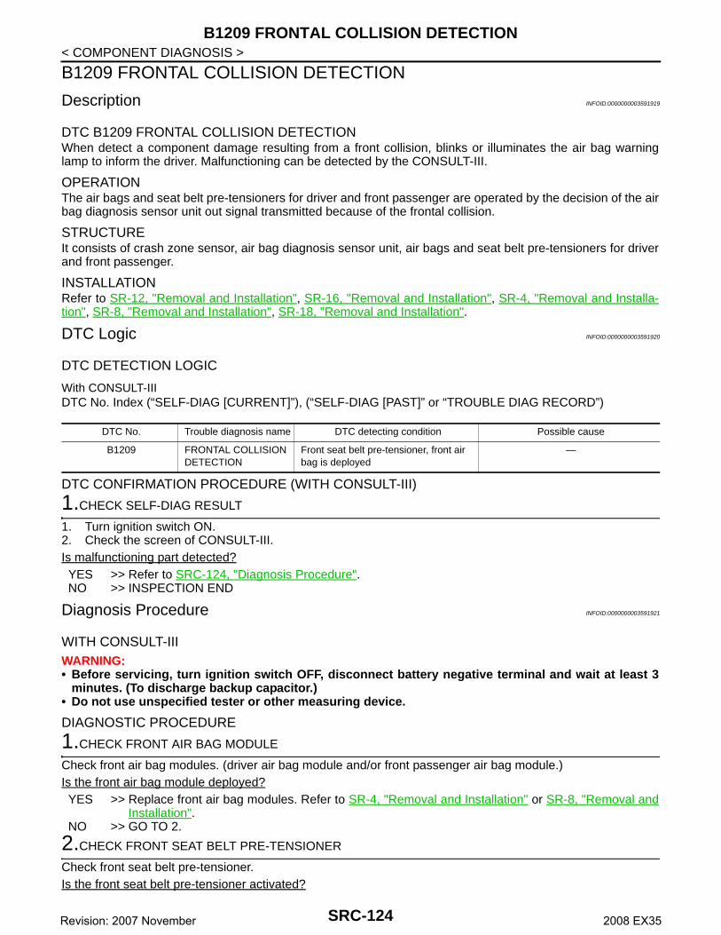
B1209 FRONTAL COLLISION DETECTION
< COMPONENT DIAGNOSIS >B1209 FRONTAL COLLISION DETECTION
Description INFOID:0000000003591919
DTC B1209 FRONTAL COLLISION DETECTIONWhen detect a component damage resulting from a front collision, blinks or illuminates the air bag warninglamp to inform the driver. Malfunctioning can be detected by the CONSULT-III.
OPERATIONThe air bags and seat belt pre-tensioners for driver and front passenger are operated by the decision of the airbag diagnosis sensor unit out signal transmitted because of the frontal collision.
STRUCTUREIt consists of crash zone sensor, air bag diagnosis sensor unit, air bags and seat belt pre-tensioners for driverand front passenger.
INSTALLATIONRefer to SR-12, "Removal and Installation", SR-16, "Removal and Installation", SR-4, "Removal and Installa-tion", SR-8, "Removal and Installation", SR-18, "Removal and Installation".
DTC Logic INFOID:0000000003591920
DTC DETECTION LOGIC
With CONSULT-IIIDTC No. Index (“SELF-DIAG [CURRENT]”), (“SELF-DIAG [PAST]” or “TROUBLE DIAG RECORD”)
DTC CONFIRMATION PROCEDURE (WITH CONSULT-III)
1.CHECK SELF-DIAG RESULT
1. Turn ignition switch ON.2. Check the screen of CONSULT-III.Is malfunctioning part detected?YES >> Refer to SRC-124, "Diagnosis Procedure".NO >> INSPECTION END
Diagnosis Procedure INFOID:0000000003591921
WITH CONSULT-IIIWARNING:• Before servicing, turn ignition switch OFF, disconnect battery negative terminal and wait at least 3
minutes. (To discharge backup capacitor.)• Do not use unspecified tester or other measuring device.
DIAGNOSTIC PROCEDURE
1.CHECK FRONT AIR BAG MODULE
Check front air bag modules. (driver air bag module and/or front passenger air bag module.)Is the front air bag module deployed?YES >> Replace front air bag modules. Refer to SR-4, "Removal and Installation" or SR-8, "Removal and
Installation".NO >> GO TO 2.
2.CHECK FRONT SEAT BELT PRE-TENSIONER
Check front seat belt pre-tensioner.Is the front seat belt pre-tensioner activated?
DTC No. Trouble diagnosis name DTC detecting condition Possible cause
B1209 FRONTAL COLLISION DETECTION
Front seat belt pre-tensioner, front air bag is deployed
—
SRC-124Revision: 2007 November 2008 EX35

B1209 FRONTAL COLLISION DETECTION
C
D
E
F
G
I
J
K
L
M
A
B
RC
N
O
P
< COMPONENT DIAGNOSIS >
S
YES >> Replace front seat belt pre-tensioner. Refer to SR-18, "Removal and Installation".NO >> GO TO 3.
3.CHECK AIR BAG DIAGNOSIS SENSOR UNIT
Check air bag diagnosis sensor unit.Is the front air bag module and/or front seat belt pre-tensioner activated?YES >> Replace air bag diagnosis sensor unit. Refer to SR-16, "Removal and Installation".NO >> GO TO 4.
4.CHECK STEERING WHEEL
Check steering wheel.Is the steering wheel normal?YES >> GO TO 5.NO >> Replace steering wheel. Refer to ST-16, "Removal and Installation".
5.CHECK SPIRAL CABLE
1. Check the continuity of spiral cable.Refer to SRC-40, "Diagnosis Procedure".2. Operate the steering wheel to check excessive heavy operation force, abnormal noise or damage.Is the inspection result normal?YES >> GO TO 6.NO >> Replace spiral cable. Refer to SR-6, "Removal and Installation".
6.CHECK WIRING HARNESS/HARNESS CONNECTOR
Check wiring harness/harness connector.Is the wiring harness/harness connector normal?YES >> GO TO 7.NO >> Replace wiring harness/harness connector.
7.FINAL CHECK
Check the screen of CONSULT-III and/or Air bag warning lamp status.Is the inspection result normal?YES >> INSPECTION ENDNO >> Check the intermittent incident. Refer to GI-38, "Intermittent Incident".
SRC-125Revision: 2007 November 2008 EX35

B1210 SIDE COLLISION DETECTION
< COMPONENT DIAGNOSIS >B1210 SIDE COLLISION DETECTION
Description INFOID:0000000003591922
DTC B1210 SIDE COLLISION DETECTIONWhen detect a component damage resulting from a side collision, brinks or illuminates the air bag warninglamp to inform the driver. Malfunctioning can be detected by the CONSULT-III.
OPERATIONThe front side air bag and side curtain air bag are operated by the decision of the air bag diagnosis sensor unitsignal of the side collision.
STRUCTUREIt consists of satellite sensor, air bag diagnosis sensor unit, front side air bag and side curtain air bag.
INSTALLATIONRefer to SR-14, "Removal and Installation", SR-16, "Removal and Installation", SR-10, "Removal and Installa-tion".
DTC Logic INFOID:0000000003591923
DTC DETECTION LOGIC
With CONSULT-IIIDTC No. Index (“SELF-DIAG [CURRENT]”), (“SELF-DIAG [PAST]” or “TROUBLE DIAG RECORD”)
DTC CONFIRMATION PROCEDURE (WITH CONSULT-III)
1.CHECK SELF-DIAG RESULT
1. Turn ignition switch ON.2. Check the screen of CONSULT-III.Is malfunctioning part detected?YES >> Refer to SRC-126, "Diagnosis Procedure".NO >> INSPECTION END
Diagnosis Procedure INFOID:0000000003591924
WITH CONSULT-IIIWARNING:• Before servicing, turn ignition switch OFF, disconnect battery negative terminal and wait at least 3
minutes. (To discharge backup capacitor)• Do not use unspecified tester or other measuring device.
DIAGNOSTIC PROCEDURE
1.CHECK FRONT SIDE AIR BAG MODULE
Check front side air bag module.Is the front side air bag module deployed?YES >> Replace front side air bag module. Refer to SE-87, "Exploded View".NO >> GO TO 2.
2.CHECK SIDE CURTAIN AIR BAG MODULE
Check side curtain air bag module.Is the side curtain air bag module deployed?YES >> Replace side curtain air bag module. Refer to SR-10, "Removal and Installation".NO >> GO TO 3.
DTC No. Trouble diagnosis name DTC detecting condition Possible cause
B1210 SIDE COLLISION DE-TECTION
Front side air bag, side curtain air bag is deployed
—
SRC-126Revision: 2007 November 2008 EX35

B1210 SIDE COLLISION DETECTION
C
D
E
F
G
I
J
K
L
M
A
B
RC
N
O
P
< COMPONENT DIAGNOSIS >
S
3.CHECK SATELLITE SENSOR
Check satellite sensor.Is the front side air bag module and/or side curtain air bag module deployed?YES >> Replace satellite sensor. Refer to SR-14, "Removal and Installation".NO >> GO TO 4.
4.CHECK AIR BAG DIAGNOSIS SENSOR UNIT
Check air bag diagnosis sensor unit.Is the front side air bag module and/or side curtain air bag module deployed?YES >> Replace air bag diagnosis sensor unit. Refer to SR-16, "Removal and Installation".NO >> GO TO 5.
5.CHECK WIRING HARNESS/HARNESS CONNECTOR
Check wiring harness/harness connector.Is the wiring harness/harness connector normal?YES >> GO TO 6.NO >> Replace wiring harness/harness connector.
6.FINAL CHECK
Check the screen of CONSULT-III and/or Air bag warning lamp status.Is the inspection result normal?YES >> INSPECTION ENDNO >> Check the intermittent incident. Refer to GI-38, "Intermittent Incident".
SRC-127Revision: 2007 November 2008 EX35
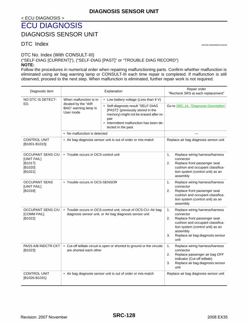
DIAGNOSIS SENSOR UNIT
< ECU DIAGNOSIS >ECU DIAGNOSISDIAGNOSIS SENSOR UNIT
DTC Index INFOID:0000000003136319
DTC No. Index (With CONSULT-III)(“SELF-DIAG [CURRENT]”), (“SELF-DIAG [PAST]” or “TROUBLE DIAG RECORD”)NOTE:Follow the procedures in numerical order when repairing malfunctioning parts. Confirm whether malfunction iseliminated using air bag warning lamp or CONSULT-III each time repair is completed. If malfunction is stillobserved, proceed to the next step. When malfunction is eliminated, further repair work is not required.
Diagnostic item ExplanationRepair order
“Recheck SRS at each replacement”
NO DTC IS DETECT-ED.
When malfunction is in-dicated by the “AIR BAG” warning lamp in User mode
• Low battery voltage (Less than 9 V)
• Self-diagnosis result “SELF-DIAG [PAST]” (previously stored in the memory) might not be erased after re-pair
• Intermittent malfunction has been de-tected in the past
Go to SRC-14, "Diagnosis Description"
• No malfunction is detected —
CONTROL UNIT[B1001-B1015]
• Air bag diagnosis sensor unit is out of order or mis-match Replace air bag diagnosis sensor unit
OCCUPANT SENS C/U[UNIT FAIL][B1017][B1020][B1021]
• Trouble occurs in OCS-control unit 1. Replace wiring harness/harness connector
2. Replace front passenger seat cushion and occupant classifica-tion system (control unit) as an assembly
OCCUPANT SENS [UNIT FAIL][B1018]
• Trouble occurs in OCS-SENSOR 1. Replace wiring harness/harness connector
2. Replace front passenger seat cushion and occupant classifica-tion system (control unit) as an assembly
OCCUPANT SENS C/U[COMM FAIL][B1022]
• Trouble occurs in OCS-control unit, circuit of OCS-CU~Air bag diagnosis sensor unit, or Air bag diagnosis sensor unit
1. Replace wiring harness/harness connector
2. Replace front passenger seat cushion and occupant classifica-tion system (control unit) as an assembly
3. Replace air bag diagnosis sensor unit
PASS A/B INDCTR CKT[B1023]
• Cut-off telltale circuit is open or shorted to ground or the circuits are shorted each other
1. Replace wiring harness/harness connector
2. Replace passenger air bag OFF indicator (Cut-off telltale)
3. Replace air bag diagnosis sensor unit
CONTROL UNIT[B1026-B1031]
• Air bag diagnosis sensor unit is out of order or mis-match Replace air bag diagnosis sensor unit
SRC-128Revision: 2007 November 2008 EX35

DIAGNOSIS SENSOR UNIT
C
D
E
F
G
I
J
K
L
M
A
B
RC
N
O
P
< ECU DIAGNOSIS >
S
CRASH ZONE SEN[UNIT FAIL][B1033][B1034]CRASH ZONE SEN[COMM FAIL][B1035][UNMATCH][B1036]
[OPEN/UPR-VB-SHORT][B1038]
[SHORT/UPR-GND-SHORT][B1040]
• Crash zone sensor is out of order 1. Replace wiring harness/harness connector
2. Replace crash zone sensor3. Replace air bag diagnosis sensor
unit
CONTROL UNIT[B1042-B1047]
• Air bag diagnosis sensor unit is out of order or mis-match Replace air bag diagnosis sensor unit
DRIVER AIRBAG MOD-ULE[OPEN][B1049] [B1054]
• Driver air bag module circuit is open (including the spiral cable) 1. Replace wiring harness/harness connector
2. Replace driver air bag module3. Replace spiral cable. Refer to
SRC-40, "Diagnosis Procedure"4. Replace air bag diagnosis sensor
unit
DRIVER AIRBAG MOD-ULE[VB-SHORT][B1050] [B1055]
• Driver air bag module circuit is shorted to some power supply cir-cuit (including the spiral cable)
DRIVER AIRBAG MOD-ULE[GND-SHORT][B1051] [B1056]
• Driver air bag module circuit is shorted to ground (including the spiral cable)
DRIVER AIRBAG MOD-ULE[SHORT][B1052] [B1057]
• Driver air bag module circuits are shorted to each other (includ-ing spiral cable)
CONTROL UNIT[B1058-B1063]
• Air bag diagnosis sensor unit is out of order or mis-match Replace air bag diagnosis sensor unit
ASSIST A/B MODULE[OPEN][B1065] [B1070]
• Front passenger air bag module circuit is open 1. Replace wiring harness/harness connector
2. Replace front passenger air bag module
3. Replace air bag diagnosis sensor unit
ASSIST A/B MODULE[VB-SHORT][B1066] [B1071]
• Front passenger air bag module circuit is shorted to some power supply circuit
ASSIST A/B MODULE[GND-SHORT][B1067] [B1072]
• Front passenger air bag module circuit is shorted to ground
ASSIST A/B MODULE[SHORT][B1068] [B1073]
• Front passenger air bag module circuits are shorted to each oth-er
CONTROL UNIT[B1074-B1079]
• Air bag diagnosis sensor unit is out of order or mis-match Replace air bag diagnosis sensor unit
Diagnostic item ExplanationRepair order
“Recheck SRS at each replacement”
SRC-129Revision: 2007 November 2008 EX35

DIAGNOSIS SENSOR UNIT
< ECU DIAGNOSIS >PRE-TEN FRONT RH[OPEN][B1081]
• Front RH seat belt pre-tensioner circuit is open 1. Replace wiring harness/harness connector
2. Replace front RH seat belt pre-tensioner
3. Replace air bag diagnosis sensor unit
PRE-TEN FRONT RH[VB-SHORT][B1082]
• Front RH seat belt pre-tensioner circuit is shorted to some power supply circuit
PRE-TEN FRONT RH[GND-SHORT][B1083]
• Front RH seat belt pre-tensioner circuit is shorted to ground
PRE-TEN FRONT RH[SHORT][B1084]
• Front RH seat belt pre-tensioner circuits are shorted to each oth-er
PRE-TEN FRONT LH[OPEN][B1086]
• Front LH seat belt pre-tensioner circuit is open 1. Replace wiring harness/harness connector
2. Replace front LH seat belt pre-tensioner
3. Replace air bag diagnosis sensor unit
PRE-TEN FRONT LH[VB-SHORT][B1087]
• Front LH seat belt pre-tensioner circuit is shorted to some power supply circuit
PRE-TEN FRONT LH[GND-SHORT][B1088]
• Front LH seat belt pre-tensioner circuit is shorted to ground
PRE-TEN FRONT LH[SHORT][B1089]
• Front LH seat belt pre-tensioner circuits are shorted to each oth-er
CONTROL UNIT[B1106-B1111]
• Air bag diagnosis sensor unit is out of order or mis-match Replace air bag diagnosis sensor unit
SATELLITE SENS RH[UNIT FAIL][B1113][B1114]SATELLITE SENS RH[COMM FAIL][B1115][UNMATCH][B1116]
• RH satellite sensor is out of order 1. Replace wiring harness/harness connector
2. Replace RH satellite sensor3. Replace air bag diagnosis sensor
unit
SATELLITE SENS LH[UNIT FAIL][B1118][B1119]SATELLITE SENS LH[COMM FAIL][B1120][UNMATCH][B1121]
• LH satellite sensor is out of order 1. Replace wiring harness/harness connector
2. Replace LH satellite sensor3. Replace air bag diagnosis sensor
unit
CONTROL UNIT[B1122-B1127]
• Air bag diagnosis sensor unit is out of order or mis-match Replace air bag diagnosis sensor unit
Diagnostic item ExplanationRepair order
“Recheck SRS at each replacement”
SRC-130Revision: 2007 November 2008 EX35
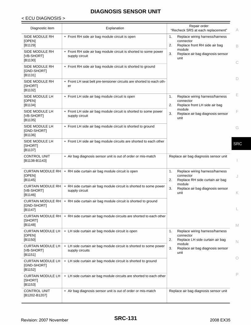
DIAGNOSIS SENSOR UNIT
C
D
E
F
G
I
J
K
L
M
A
B
RC
N
O
P
< ECU DIAGNOSIS >
S
SIDE MODULE RH[OPEN][B1129]
• Front RH side air bag module circuit is open 1. Replace wiring harness/harness connector
2. Replace front RH side air bag module
3. Replace air bag diagnosis sensor unit
SIDE MODULE RH[VB-SHORT][B1130]
• Front RH side air bag module circuit is shorted to some power supply circuit
SIDE MODULE RH[GND-SHORT][B1131]
• Front RH side air bag module circuit is shorted to ground
SIDE MODULE RH[SHORT][B1132]
• Front LH seat belt pre-tensioner circuits are shorted to each oth-er
SIDE MODULE LH[OPEN][B1134]
• Front LH side air bag module circuit is open 1. Replace wiring harness/harness connector
2. Replace front LH side air bag module
3. Replace air bag diagnosis sensor unit
SIDE MODULE LH[VB-SHORT][B1135]
• Front LH side air bag module circuit is shorted to some power supply circuit
SIDE MODULE LH[GND-SHORT][B1136]
• Front LH side air bag module circuit is shorted to ground
SIDE MODULE LH[SHORT][B1137]
• Front LH side air bag module circuits are shorted to each other
CONTROL UNIT[B1138-B1143]
• Air bag diagnosis sensor unit is out of order or mis-match Replace air bag diagnosis sensor unit
CURTAIN MODULE RH[OPEN][B1145]
• RH side curtain air bag module circuit is open 1. Replace wiring harness/harness connector
2. Replace RH side curtain air bag module
3. Replace air bag diagnosis sensor unit
CURTAIN MODULE RH[VB-SHORT][B1146]
• RH side curtain air bag module circuit is shorted to some power supply circuit
CURTAIN MODULE RH[GND-SHORT][B1147]
• RH side curtain air bag module circuit is shorted to ground
CURTAIN MODULE RH[SHORT][B1148]
• RH side curtain air bag module circuits are shorted to each other
CURTAIN MODULE LH[OPEN][B1150]
• LH side curtain air bag module circuit is open 1. Replace wiring harness/harness connector
2. Replace LH side curtain air bag module
3. Replace air bag diagnosis sensor unit
CURTAIN MODULE LH[VB-SHORT][B1151]
• LH side curtain air bag module circuit is shorted to some power supply circuits
CURTAIN MODULE LH[GND-SHORT][B1152]
• LH side curtain air bag module circuit is shorted to ground
CURTAIN MODULE LH[SHORT][B1153]
• LH side curtain air bag module circuits are shorted to each other
CONTROL UNIT[B1202-B1207]
• Air bag diagnosis sensor unit is out of order or mis-match Replace air bag diagnosis sensor unit
Diagnostic item ExplanationRepair order
“Recheck SRS at each replacement”
SRC-131Revision: 2007 November 2008 EX35
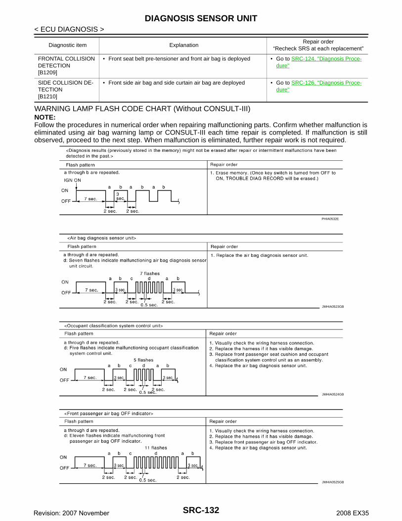
DIAGNOSIS SENSOR UNIT
< ECU DIAGNOSIS >WARNING LAMP FLASH CODE CHART (Without CONSULT-III)NOTE:Follow the procedures in numerical order when repairing malfunctioning parts. Confirm whether malfunction iseliminated using air bag warning lamp or CONSULT-III each time repair is completed. If malfunction is stillobserved, proceed to the next step. When malfunction is eliminated, further repair work is not required.
FRONTAL COLLISION DETECTION[B1209]
• Front seat belt pre-tensioner and front air bag is deployed • Go to SRC-124, "Diagnosis Proce-dure"
SIDE COLLISION DE-TECTION[B1210]
• Front side air bag and side curtain air bag are deployed • Go to SRC-126, "Diagnosis Proce-dure"
Diagnostic item ExplanationRepair order
“Recheck SRS at each replacement”
PHIA0532E
JMHIA0523GB
JMHIA0524GB
JMHIA0525GB
SRC-132Revision: 2007 November 2008 EX35

DIAGNOSIS SENSOR UNIT
C
D
E
F
G
I
J
K
L
M
A
B
RC
N
O
P
< ECU DIAGNOSIS >
S
JMHIA0526GB
JMHIA0527GB
JMHIA0528GB
JMHIA0529GB
JMHIA0530GB
SRC-133Revision: 2007 November 2008 EX35

DIAGNOSIS SENSOR UNIT
< ECU DIAGNOSIS >JMHIA0531GB
JMHIA0532GB
JMHIA0533GB
JMHIA0534GB
JMHIA0535GB
SRC-134Revision: 2007 November 2008 EX35
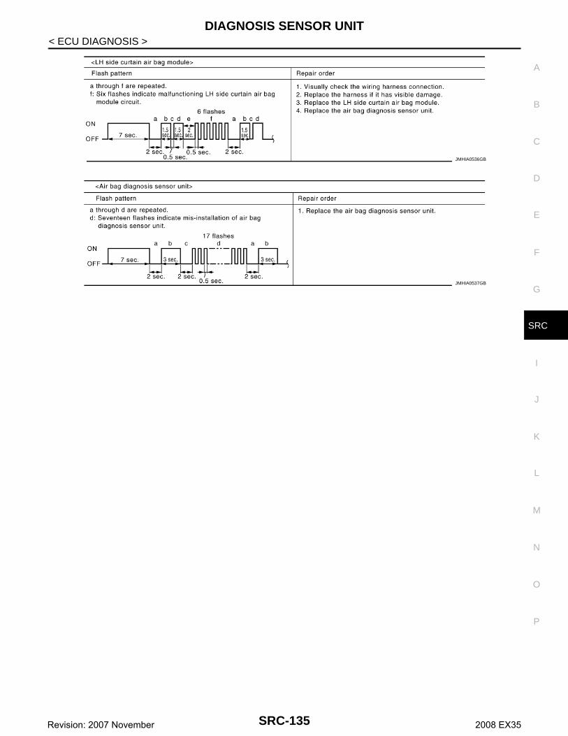
DIAGNOSIS SENSOR UNIT
C
D
E
F
G
I
J
K
L
M
A
B
RC
N
O
P
< ECU DIAGNOSIS >
S
JMHIA0536GB
JMHIA0537GB
SRC-135Revision: 2007 November 2008 EX35
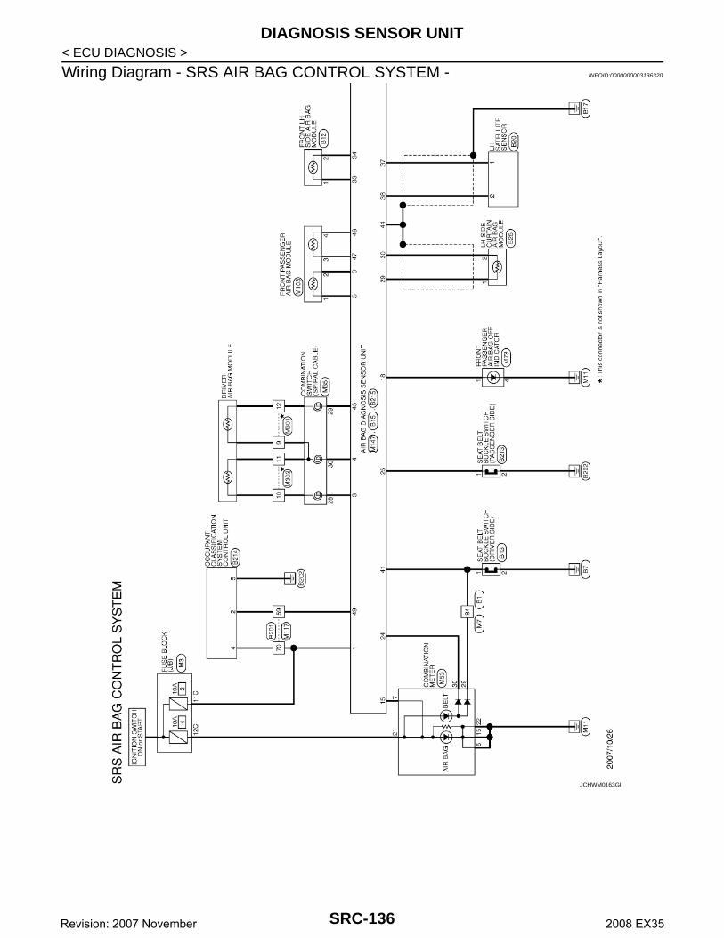
DIAGNOSIS SENSOR UNIT
< ECU DIAGNOSIS >Wiring Diagram - SRS AIR BAG CONTROL SYSTEM - INFOID:0000000003136320
JCHWM0163GB
SRC-136Revision: 2007 November 2008 EX35
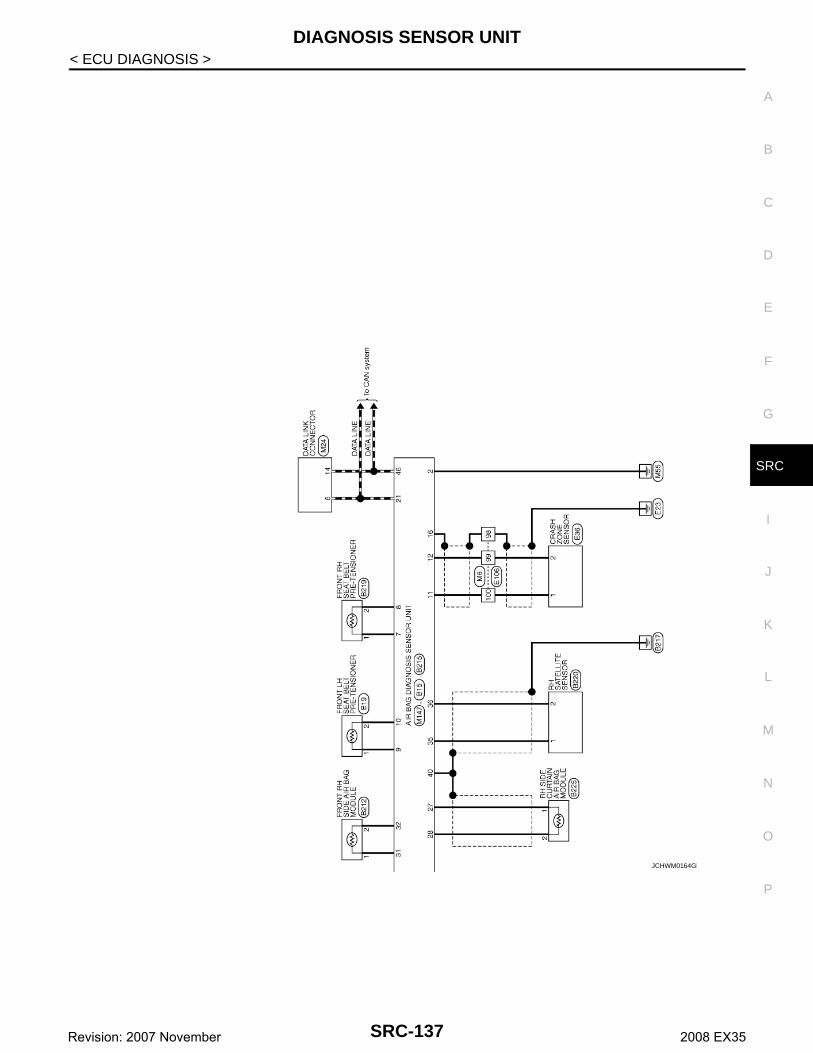
DIAGNOSIS SENSOR UNIT
C
D
E
F
G
I
J
K
L
M
A
B
RC
N
O
P
< ECU DIAGNOSIS >
S
JCHWM0164GB
SRC-137Revision: 2007 November 2008 EX35

DIAGNOSIS SENSOR UNIT
< ECU DIAGNOSIS >JCHWM0165GB
SRC-138Revision: 2007 November 2008 EX35

DIAGNOSIS SENSOR UNIT
C
D
E
F
G
I
J
K
L
M
A
B
RC
N
O
P
< ECU DIAGNOSIS >
S
JCHWM0166GB
SRC-139Revision: 2007 November 2008 EX35
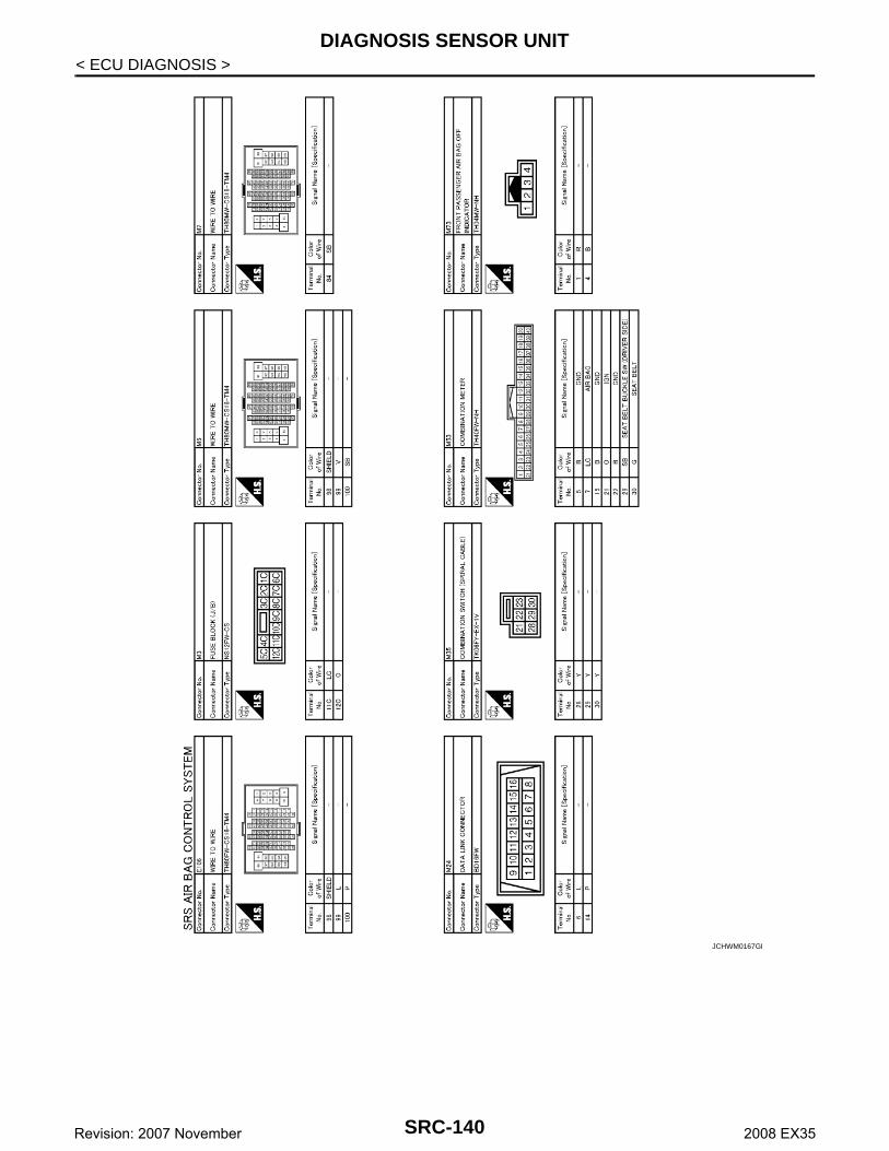
DIAGNOSIS SENSOR UNIT
< ECU DIAGNOSIS >JCHWM0167GB
SRC-140Revision: 2007 November 2008 EX35
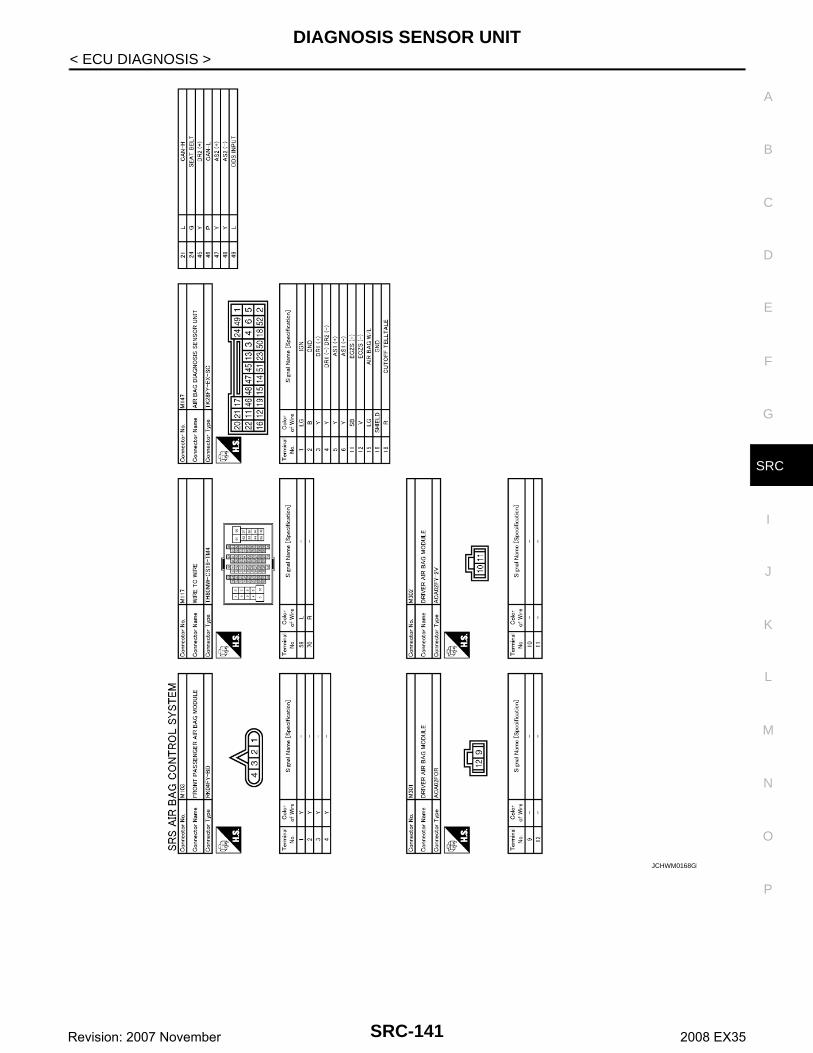
DIAGNOSIS SENSOR UNIT
C
D
E
F
G
I
J
K
L
M
A
B
RC
N
O
P
< ECU DIAGNOSIS >
S
JCHWM0168GB
SRC-141Revision: 2007 November 2008 EX35

SRS AIR BAG WARNING LAMP DOES NOT TURN OFF
< SYMPTOM DIAGNOSIS >SYMPTOM DIAGNOSISSRS AIR BAG WARNING LAMP DOES NOT TURN OFF
Diagnosis Procedure INFOID:0000000003136321
1.CHECK FRONT AIR BAG MODULE
Check the deployment of front air bag module.Is air bag module deployed?YES >> Refer to SR-4, "Removal and Installation" or SR-8, "Removal and Installation".NO >> GO TO 2.
2.CHECK AIR BAG FUSE
Check the air bag fuse. Refer to PG-99, "Fuse and Fusible Link Arrangement".Is 10A fuse [No.2, located in fuse block (J/B)] normal?YES >> GO TO 4.NO >> GO TO 3.
3.CHECK AIR BAG FUSE AGAIN
Replace air bag fuse and turn ignition switch ON.Did the air bag fuse blow again?YES >> Repair or replace main harness.NO >> INSPECTION END
4.CHECK AIR BAG DIAGNOSIS SENSOR UNIT
Check the screen of CONSULT-III.Is the inspection result normal?YES >> GO TO 5.NO >> Replace air bag diagnosis sensor unit. Refer to SR-16, "Removal and Installation".
5.CHECK HARNESS CONNECTION
Check harness connection between air bag warning lamp and air bag diagnosis sensor unit.Is the inspection result normal?YES >> Check the intermittent incident. Refer to GI-38, "Intermittent Incident".NO >> Replace wiring harness connector.
SRC-142Revision: 2007 November 2008 EX35
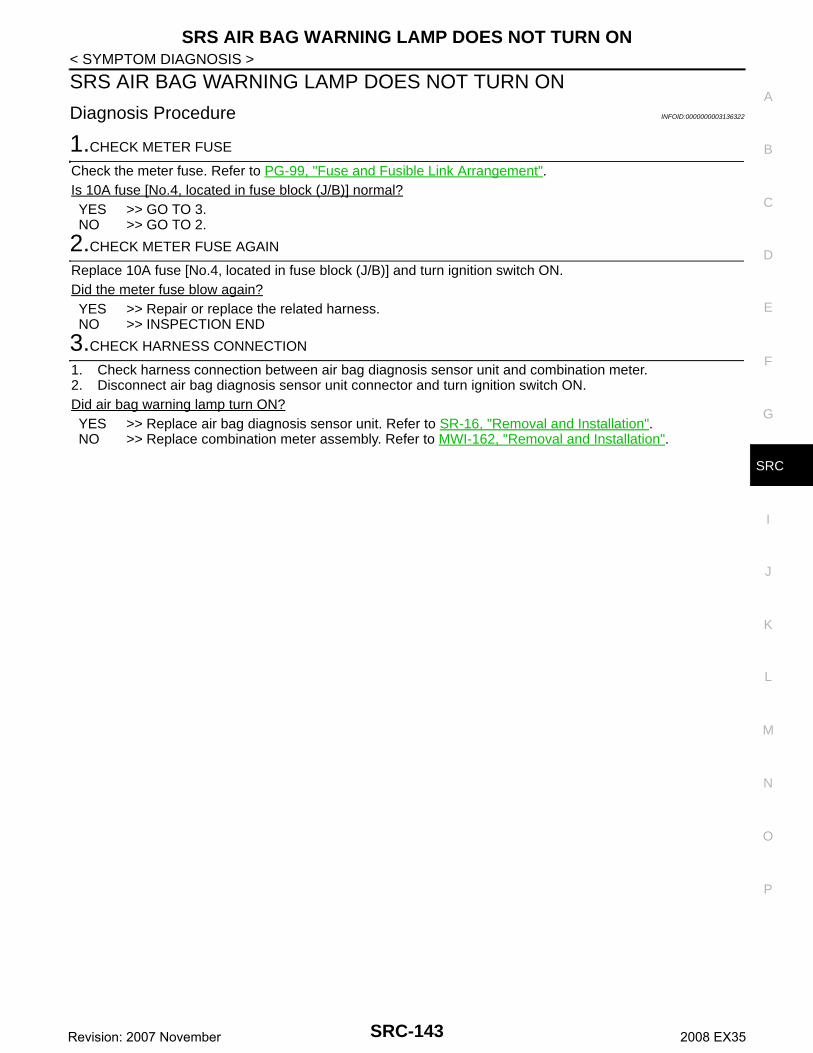
SRS AIR BAG WARNING LAMP DOES NOT TURN ON
C
D
E
F
G
I
J
K
L
M
A
B
RC
N
O
P
< SYMPTOM DIAGNOSIS >
S
SRS AIR BAG WARNING LAMP DOES NOT TURN ON
Diagnosis Procedure INFOID:0000000003136322
1.CHECK METER FUSE
Check the meter fuse. Refer to PG-99, "Fuse and Fusible Link Arrangement".Is 10A fuse [No.4, located in fuse block (J/B)] normal?YES >> GO TO 3.NO >> GO TO 2.
2.CHECK METER FUSE AGAIN
Replace 10A fuse [No.4, located in fuse block (J/B)] and turn ignition switch ON.Did the meter fuse blow again?YES >> Repair or replace the related harness.NO >> INSPECTION END
3.CHECK HARNESS CONNECTION
1. Check harness connection between air bag diagnosis sensor unit and combination meter.2. Disconnect air bag diagnosis sensor unit connector and turn ignition switch ON.Did air bag warning lamp turn ON?YES >> Replace air bag diagnosis sensor unit. Refer to SR-16, "Removal and Installation".NO >> Replace combination meter assembly. Refer to MWI-162, "Removal and Installation".
SRC-143Revision: 2007 November 2008 EX35

PASSENGER SEAT BELT WARNING SYSTEM
< SYMPTOM DIAGNOSIS >PASSENGER SEAT BELT WARNING SYSTEM
Diagnosis Procedure INFOID:0000000003136323
1.CHECK THE SYSTEM 1
Check the seat belt warning lamp function.Seat belt warning lamp turns ON in the following conditions.• Driver seat belt is fastened.• Occupant is on passenger seat.• Passenger seat belt is not fastened. Is the inspection result normal?YES >> GO TO 2.NO >> Check the followings.
• Harness between air bag diagnosis sensor unit and combination meter.• Seat belt buckle switch (passenger side) circuit.• Seat belt buckle switch (passenger side).
If these are OK, replace air bag diagnosis sensor unit.
2.CHECK THE SYSTEM 2
Check the seat belt warning lamp function.Seat belt warning lamp turns OFF in the following conditions.• Driver seat belt is fastened.• Occupant is on passenger seat.• Passenger seat belt is fastened.Is the inspection result normal?YES >> System is OK.NO >> Check the followings.
• Seat belt buckle switch (passenger side) circuit.• Seat belt buckle switch (passenger side).
If these are OK, replace air bag diagnosis sensor unit.
SRC-144Revision: 2007 November 2008 EX35
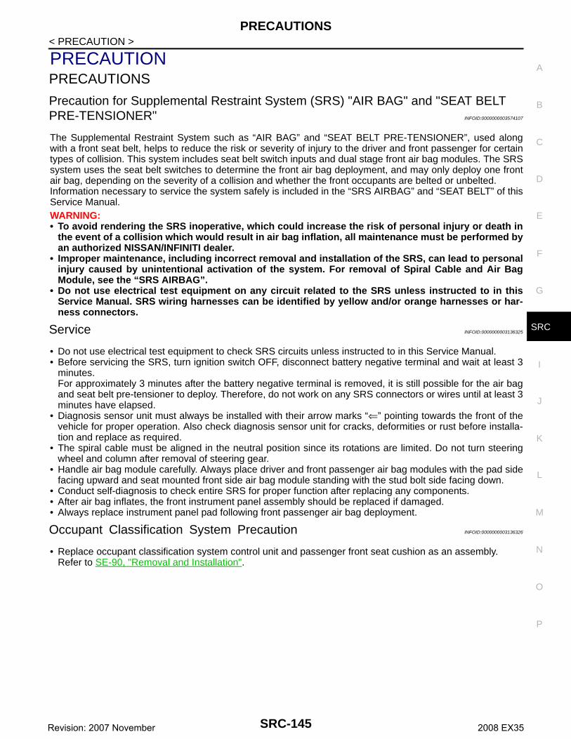
PRECAUTIONS
C
D
E
F
G
I
J
K
L
M
A
B
RC
N
O
P
< PRECAUTION >
S
PRECAUTIONPRECAUTIONS
Precaution for Supplemental Restraint System (SRS) "AIR BAG" and "SEAT BELT PRE-TENSIONER" INFOID:0000000003574107
The Supplemental Restraint System such as “AIR BAG” and “SEAT BELT PRE-TENSIONER”, used alongwith a front seat belt, helps to reduce the risk or severity of injury to the driver and front passenger for certaintypes of collision. This system includes seat belt switch inputs and dual stage front air bag modules. The SRSsystem uses the seat belt switches to determine the front air bag deployment, and may only deploy one frontair bag, depending on the severity of a collision and whether the front occupants are belted or unbelted.Information necessary to service the system safely is included in the “SRS AIRBAG” and “SEAT BELT” of thisService Manual.WARNING:• To avoid rendering the SRS inoperative, which could increase the risk of personal injury or death in
the event of a collision which would result in air bag inflation, all maintenance must be performed byan authorized NISSAN/INFINITI dealer.
• Improper maintenance, including incorrect removal and installation of the SRS, can lead to personalinjury caused by unintentional activation of the system. For removal of Spiral Cable and Air BagModule, see the “SRS AIRBAG”.
• Do not use electrical test equipment on any circuit related to the SRS unless instructed to in thisService Manual. SRS wiring harnesses can be identified by yellow and/or orange harnesses or har-ness connectors.
Service INFOID:0000000003136325
• Do not use electrical test equipment to check SRS circuits unless instructed to in this Service Manual.• Before servicing the SRS, turn ignition switch OFF, disconnect battery negative terminal and wait at least 3
minutes.For approximately 3 minutes after the battery negative terminal is removed, it is still possible for the air bagand seat belt pre-tensioner to deploy. Therefore, do not work on any SRS connectors or wires until at least 3minutes have elapsed.
• Diagnosis sensor unit must always be installed with their arrow marks “⇐” pointing towards the front of thevehicle for proper operation. Also check diagnosis sensor unit for cracks, deformities or rust before installa-tion and replace as required.
• The spiral cable must be aligned in the neutral position since its rotations are limited. Do not turn steeringwheel and column after removal of steering gear.
• Handle air bag module carefully. Always place driver and front passenger air bag modules with the pad sidefacing upward and seat mounted front side air bag module standing with the stud bolt side facing down.
• Conduct self-diagnosis to check entire SRS for proper function after replacing any components.• After air bag inflates, the front instrument panel assembly should be replaced if damaged.• Always replace instrument panel pad following front passenger air bag deployment.
Occupant Classification System Precaution INFOID:0000000003136326
• Replace occupant classification system control unit and passenger front seat cushion as an assembly.Refer to SE-90, "Removal and Installation".
SRC-145Revision: 2007 November 2008 EX35