Restoration of face-centered cubic metals subjected to kinetic spraying
11
Met. Mater. Int., Vol. 19, No. 2 (2013), pp. 283~293 doi: 10.1007/s12540-013-2024-z Restoration of Face-Centered Cubic Metals Subjected to Kinetic Spraying Kicheol Kang, Gyuyeol Bae, and Changhee Lee * Kinetic Spray Coating Laboratory (NRL), Division of Materials Science & Engineering, Hanyang University, 17 Haengdang-dong, Seongdong-ku, Seoul 133-791, Korea (received date: 6 February 2012 / accepted date: 16 April 2012) Deformation mode and restoration of face-centered cubic (FCC) metal (Al, Ni, and Cu) particles sub- jected to kinetic spraying (KS) were investigated. The FCC metal particles were accelerated to supersonic velocity by high pressure process gas, and collided with substrates or previously deposited coating layer. The high velocity impact of in-flight particles and their successive deposition leads to severe plastic defor- mation at ultra-high strain rate and the dissipation of heat energy from the plasticity. Accordingly, highly strained interface undergoes restoration to stabilize strained area during KS. Although Al, Ni, and Cu have equivalent slip systems {111} <110>, the different physical and metallurgical properties of the FCC metals differentiate the deformation mode and lead to variations in static recovery and recrystallization rates. The deformation and restoration behavior of KS FCC metals are discussed, taking into account the physical and metallurgical factors such as stacking fault energy, dislocation mobility, diffusivity, and melting point. Key words: metals, coating, recovery, recrystallization, severe plastic deformation 1. INTRODUCTION Kinetic spraying (KS) is a unique coating process that uti- lizes the severe plastic deformation of colliding micron-sized particles. In KS process, particles are accelerated to super- sonic velocities by the drag force of high pressure process gas in conjunction with the geometrical contribution of a converge-diverge nozzle [1-9]. Upon impact of the in-flight particle, severe plastic deformation occurs, and, in particular, strain localization at the particle interface occurs. The simu- lation results of particle impact indicated that the strain rate at the particle interface approaches 1.0×10 6 -0.5×10 9 s −1 [10- 17]. In such high strain rate deformation, the heat energy dis- sipated from the plastic deformation is stored in an adiabatic state in the deforming area and increases the temperature of the particle, promoting plastic deformation [9-16]. The tem- perature of the particle interface in the adiabatic state reaches the particle melting point [9,17,18]. The bonding or deposi- tion of colliding particles is generated from the plastic defor- mation energy of the particles. Thus, the plastic deformability of a particle is an important criterion that determines deposi- tion in KS. The metallic materials, such as Al [1-3,16,18,20], Cu [8,11,19-21], Ni [16,19,20], Ti [6,17], and metallic alloys [22,23], that have high plastic deformability are principally applied to KS. The high strain at the interface during the collision of par- ticles results in interfacial bonding and concurrently drives the interface metastable state with high dislocation density. Borchers et al. [19,20] and Li et al . [24] reported that dynamic recrystallization (DRX) can occur at the metallic particle interface. DRX is a part of dynamic restoration and partially reduces the strain energy of the interface. However, the DRX zone at the interface is narrow; thus, a high fraction of the strain energy at the strain interface remains. Figure 1(a) shows the schematics of the thermal history experienced by the deposited particle interface during KS. For an instant, i.e., approximately 4×10 −8 -8×10 −8 s, the temperature of the parti- cle interface increases while in the adiabatic state, after which, the particle temperature rapidly decreases [11,18]. The subsequent impact of in-flight particles heats the coating during KS (Fig. 1(b)). Recently, King et al. [8] reported that KS Cu coating was isothermally heated during KS with a lit- tle temperature fluctuation. The strained interface with a high dislocation density may lead to static restoration (SRV or SRX), powered by the heat energy of KS. Deformation mode and restoration of FCC metal (Al, Ni, and Cu) particles subjected to KS were investigated taking into account their physical and metallurgical factors. Since deformation mode and restoration of the FCC metallic coat- ings dominantly influence the microstructural evolution of the KS coatings, the fundamental understanding of the defor- mation mode and dynamic or static restoration is important to control the microstructural factor of KS coatings. The Al, *Corresponding author: [email protected] ©KIM and Springer, Published 10 March 2013
-
Upload
changhee-lee -
Category
Documents
-
view
215 -
download
2
Transcript of Restoration of face-centered cubic metals subjected to kinetic spraying

Met. Mater. Int., Vol. 19, No. 2 (2013), pp. 283~293doi: 10.1007/s12540-013-2024-z
Restoration of Face-Centered Cubic Metals Subjected to Kinetic Spraying
Kicheol Kang, Gyuyeol Bae, and Changhee Lee*
Kinetic Spray Coating Laboratory (NRL), Division of Materials Science & Engineering,Hanyang University, 17 Haengdang-dong, Seongdong-ku, Seoul 133-791, Korea
(received date: 6 February 2012 / accepted date: 16 April 2012)
Deformation mode and restoration of face-centered cubic (FCC) metal (Al, Ni, and Cu) particles sub-jected to kinetic spraying (KS) were investigated. The FCC metal particles were accelerated to supersonicvelocity by high pressure process gas, and collided with substrates or previously deposited coating layer.The high velocity impact of in-flight particles and their successive deposition leads to severe plastic defor-mation at ultra-high strain rate and the dissipation of heat energy from the plasticity. Accordingly, highlystrained interface undergoes restoration to stabilize strained area during KS. Although Al, Ni, and Cu haveequivalent slip systems {111} <110>, the different physical and metallurgical properties of the FCC metalsdifferentiate the deformation mode and lead to variations in static recovery and recrystallization rates. Thedeformation and restoration behavior of KS FCC metals are discussed, taking into account the physical andmetallurgical factors such as stacking fault energy, dislocation mobility, diffusivity, and melting point.
Key words: metals, coating, recovery, recrystallization, severe plastic deformation
1. INTRODUCTION
Kinetic spraying (KS) is a unique coating process that uti-lizes the severe plastic deformation of colliding micron-sizedparticles. In KS process, particles are accelerated to super-sonic velocities by the drag force of high pressure processgas in conjunction with the geometrical contribution of aconverge-diverge nozzle [1-9]. Upon impact of the in-flightparticle, severe plastic deformation occurs, and, in particular,strain localization at the particle interface occurs. The simu-lation results of particle impact indicated that the strain rateat the particle interface approaches 1.0×10⁶-0.5×10⁹s−1 [10-17]. In such high strain rate deformation, the heat energy dis-sipated from the plastic deformation is stored in an adiabaticstate in the deforming area and increases the temperature ofthe particle, promoting plastic deformation [9-16]. The tem-perature of the particle interface in the adiabatic state reachesthe particle melting point [9,17,18]. The bonding or deposi-tion of colliding particles is generated from the plastic defor-mation energy of the particles. Thus, the plastic deformabilityof a particle is an important criterion that determines deposi-tion in KS. The metallic materials, such as Al [1-3,16,18,20],Cu [8,11,19-21], Ni [16,19,20], Ti [6,17], and metallic alloys[22,23], that have high plastic deformability are principallyapplied to KS.
The high strain at the interface during the collision of par-ticles results in interfacial bonding and concurrently drivesthe interface metastable state with high dislocation density.Borchers et al. [19,20] and Li et al. [24] reported that dynamicrecrystallization (DRX) can occur at the metallic particleinterface. DRX is a part of dynamic restoration and partiallyreduces the strain energy of the interface. However, the DRXzone at the interface is narrow; thus, a high fraction of thestrain energy at the strain interface remains. Figure 1(a) showsthe schematics of the thermal history experienced by thedeposited particle interface during KS. For an instant, i.e.,approximately 4×10⁻⁸-8×10⁻⁸ s, the temperature of the parti-cle interface increases while in the adiabatic state, afterwhich, the particle temperature rapidly decreases [11,18].The subsequent impact of in-flight particles heats the coatingduring KS (Fig. 1(b)). Recently, King et al. [8] reported thatKS Cu coating was isothermally heated during KS with a lit-tle temperature fluctuation. The strained interface with a highdislocation density may lead to static restoration (SRV orSRX), powered by the heat energy of KS.
Deformation mode and restoration of FCC metal (Al, Ni,and Cu) particles subjected to KS were investigated takinginto account their physical and metallurgical factors. Sincedeformation mode and restoration of the FCC metallic coat-ings dominantly influence the microstructural evolution ofthe KS coatings, the fundamental understanding of the defor-mation mode and dynamic or static restoration is importantto control the microstructural factor of KS coatings. The Al,
*Corresponding author: [email protected]©KIM and Springer, Published 10 March 2013

284 Kicheol Kang et al.
Ni, and Cu have equivalent slip systems; however, they havedifferent SFE, dislocation mobility, diffusivity, and meltingpoint [25]. In this study, the Al, Ni, and Cu powders weredeposited above their critical velocities. And the correlationbetween deformation mode and restoration of KS Al, Ni,and Cu coatings, and their physical and metallurgical proper-ties are investigated on a basis of microstructural and physi-cal metallurgical analysis.
2. EXPERIMENTAL PROCEDURES
2.1. Powder and sprayingCommercially pure Al (AL-104, Praxair), Ni (56F-NS,
Sulzer-Metco), and Cu (H. C. Starks) powders were used.Figures 2(a-c) show the spherical morphologies of the FCCpowders. Figure 2(d) shows the size distribution of powders,ranging from 45 to 90 µm for Al (mean of 60 µm), 25 to 60 µmfor Ni (mean of 40 µm), and 15 to 35 µm for Cu (mean of 25µm).
Fig. 1. Schematic representation of KS: (a) Thermal history of particle interface, and (b) Deformation and restoration process in KS.
Fig. 2. SEM micrographs of powder morphology: (a) Al, (b) Ni, and (c) Cu powders. (d) Size distribution, and (e) XRD analysis of the powders.
Restoration of Face-Centered Cubic Metals Subjected to Kinetic Spraying 285
A commercial KS system (KINETIC 3000, CGT) with aconverge-diverge tungsten carbide nozzle was used. Theequipment and the KS process are explained in detail in theliterature [1-9]. Table 1 summarizes the process parameters,which were designed to accelerate the FCC metal particlesabove the critical velocity. The process gas temperature wasfixed at 573 K to minimize the effects of temperature on res-toration during KS. Al 1050 alloy plates were used as sub-strate and were polished prior to deposition.
2.2. AnalysisThe cross sections of the Al, Ni, and Cu coatings were
etched using the etching solutions 3 ml HF + 6 ml HNO3 +100 ml H2O, 4 g CuSO4 + 20 ml HCl + 20 ml H2O, and 120 mlC2H5OH + 30 ml HCl + 3 g FeCl3, respectively, and were ana-lyzed using scanning electron microscopy (SEM) (JAM5600,JEOL). For the transmission electron microscopy (TEM) speci-men preparation, coatings were thinned to approximately100 µm by mechanical polishing. Thin foils were punched tomake a 3 mm diameter disc. The thickness of the thin foil wasreduced to around 100 nm using the electrolytic jet polishingmethod (Tenupol-3, Struers). A TEM (JEM2000 EX-II, JEOL)was used to analyze the microstructures, while the grain size,distribution, and aspect ratio were measured using imageanalysis software (Image-Pro Plus, Media Cybernetics).
3. RESULTS
3.1. Powder analysisThe XRD analysis of the FCC powders illustrated the
FCC structure by showing typical FCC peak combinations,as shown in Fig. 2(e). The Al and Cu powders were manu-factured using gas atomization, during which the Al and Cu
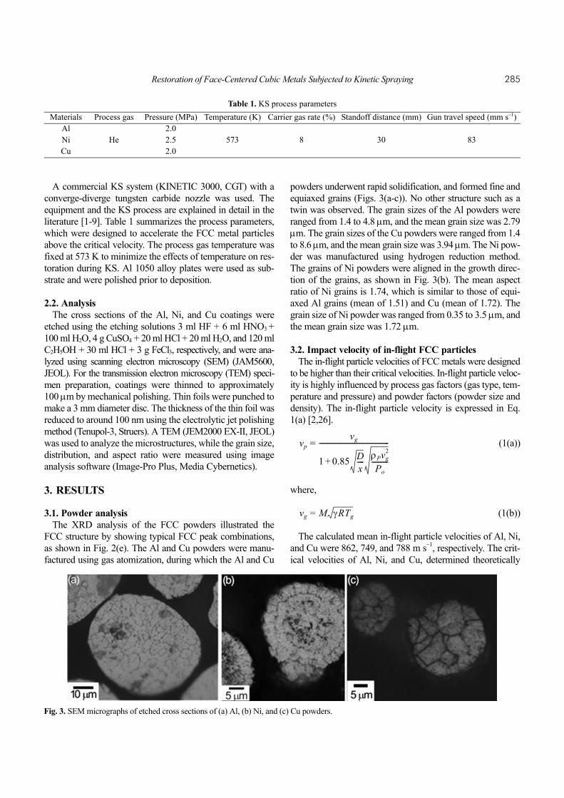
powders underwent rapid solidification, and formed fine andequiaxed grains (Figs. 3(a-c)). No other structure such as atwin was observed. The grain sizes of the Al powders wereranged from 1.4 to 4.8 µm, and the mean grain size was 2.79µm. The grain sizes of the Cu powders were ranged from 1.4to 8.6 µm, and the mean grain size was 3.94 µm. The Ni pow-der was manufactured using hydrogen reduction method.The grains of Ni powders were aligned in the growth direc-tion of the grains, as shown in Fig. 3(b). The mean aspectratio of Ni grains is 1.74, which is similar to those of equi-axed Al grains (mean of 1.51) and Cu (mean of 1.72). Thegrain size of Ni powder was ranged from 0.35 to 3.5 µm, andthe mean grain size was 1.72 µm.
3.2. Impact velocity of in-flight FCC particlesThe in-flight particle velocities of FCC metals were designed
to be higher than their critical velocities. In-flight particle veloc-ity is highly influenced by process gas factors (gas type, tem-perature and pressure) and powder factors (powder size anddensity). The in-flight particle velocity is expressed in Eq.1(a) [2,26].
(1(a))
where,
(1(b))
The calculated mean in-flight particle velocities of Al, Ni,and Cu were 862, 749, and 788 m s−1, respectively. The crit-ical velocities of Al, Ni, and Cu, determined theoretically
vpvg
1 0.85 Dx---- ρPvg
2
Po----------+
------------------------------------------=
vg M γRTg=
Table 1. KS process parametersMaterials Process gas Pressure (MPa) Temperature (K) Carrier gas rate (%) Standoff distance (mm) Gun travel speed (mm s−1)
Al 2.0Ni He 2.5 573 8 30 83Cu 2.0
Fig. 3. SEM micrographs of etched cross sections of (a) Al, (b) Ni, and (c) Cu powders.
286 Kicheol Kang et al.
and experimentally, were 750-760, 600-620, and 570-585 ms−1, respectively [2,11,13]. Each mean particle velocity of anFCC metal powder was significantly higher than its criticalvelocity. Thus, FCC powder can obtain sufficient kinetic energyfor deposition in KS. The deposition efficiencies of Al, Ni,and Cu in KS were 83, 72, and 86%, respectively.
3.3. Deposited microstructures of KS FCC metal coatingsThe sufficient velocity impact of FCC powders led to the
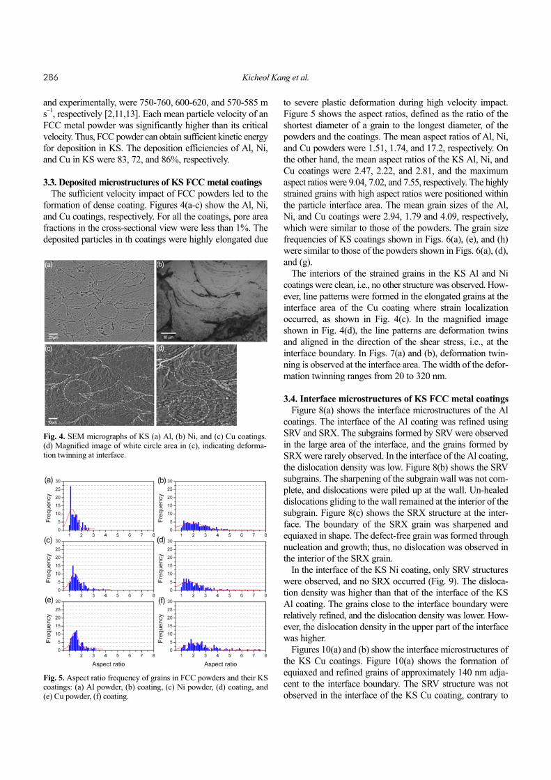
formation of dense coating. Figures 4(a-c) show the Al, Ni,and Cu coatings, respectively. For all the coatings, pore areafractions in the cross-sectional view were less than 1%. Thedeposited particles in th coatings were highly elongated due
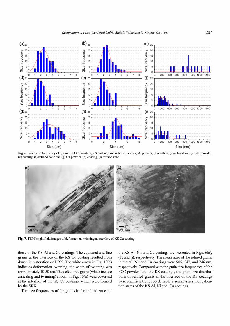
to severe plastic deformation during high velocity impact.Figure 5 shows the aspect ratios, defined as the ratio of theshortest diameter of a grain to the longest diameter, of thepowders and the coatings. The mean aspect ratios of Al, Ni,and Cu powders were 1.51, 1.74, and 17.2, respectively. Onthe other hand, the mean aspect ratios of the KS Al, Ni, andCu coatings were 2.47, 2.22, and 2.81, and the maximumaspect ratios were 9.04, 7.02, and 7.55, respectively. The highlystrained grains with high aspect ratios were positioned withinthe particle interface area. The mean grain sizes of the Al,Ni, and Cu coatings were 2.94, 1.79 and 4.09, respectively,which were similar to those of the powders. The grain sizefrequencies of KS coatings shown in Figs. 6(a), (e), and (h)were similar to those of the powders shown in Figs. 6(a), (d),and (g).
The interiors of the strained grains in the KS Al and Nicoatings were clean, i.e., no other structure was observed. How-ever, line patterns were formed in the elongated grains at theinterface area of the Cu coating where strain localizationoccurred, as shown in Fig. 4(c). In the magnified imageshown in Fig. 4(d), the line patterns are deformation twinsand aligned in the direction of the shear stress, i.e., at theinterface boundary. In Figs. 7(a) and (b), deformation twin-ning is observed at the interface area. The width of the defor-mation twinning ranges from 20 to 320 nm.
3.4. Interface microstructures of KS FCC metal coatingsFigure 8(a) shows the interface microstructures of the Al
coatings. The interface of the Al coating was refined usingSRV and SRX. The subgrains formed by SRV were observedin the large area of the interface, and the grains formed bySRX were rarely observed. In the interface of the Al coating,the dislocation density was low. Figure 8(b) shows the SRVsubgrains. The sharpening of the subgrain wall was not com-plete, and dislocations were piled up at the wall. Un-healeddislocations gliding to the wall remained at the interior of thesubgrain. Figure 8(c) shows the SRX structure at the inter-face. The boundary of the SRX grain was sharpened andequiaxed in shape. The defect-free grain was formed throughnucleation and growth; thus, no dislocation was observed inthe interior of the SRX grain.
In the interface of the KS Ni coating, only SRV structureswere observed, and no SRX occurred (Fig. 9). The disloca-tion density was higher than that of the interface of the KSAl coating. The grains close to the interface boundary wererelatively refined, and the dislocation density was lower. How-ever, the dislocation density in the upper part of the interfacewas higher.
Figures 10(a) and (b) show the interface microstructures ofthe KS Cu coatings. Figure 10(a) shows the formation ofequiaxed and refined grains of approximately 140 nm adja-cent to the interface boundary. The SRV structure was notobserved in the interface of the KS Cu coating, contrary to
Fig. 4. SEM micrographs of KS (a) Al, (b) Ni, and (c) Cu coatings.(d) Magnified image of white circle area in (c), indicating deforma-tion twinning at interface.
Fig. 5. Aspect ratio frequency of grains in FCC powders and their KScoatings: (a) Al powder, (b) coating, (c) Ni powder, (d) coating, and(e) Cu powder, (f) coating.
Restoration of Face-Centered Cubic Metals Subjected to Kinetic Spraying 287
those of the KS Al and Cu coatings. The equiaxed and finegrains at the interface of the KS Cu coating resulted fromdynamic restoration or DRX. The white arrow in Fig. 10(a)indicates deformation twinning, the width of twinning wasapproximately 10-50 nm. The defect-free grains (which includeannealing and twinning) shown in Fig. 10(a) were observedat the interface of the KS Cu coatings, which were formedby the SRX.
The size frequencies of the grains in the refined zones of
the KS Al, Ni, and Cu coatings are presented in Figs. 6(c),(f), and (i), respectively. The mean sizes of the refined grainsin the Al, Ni, and Cu coatings were 905, 247, and 246 nm,respectively. Compared with the grain size frequencies of theFCC powders and the KS coatings, the grain size distribu-tions of refined grains at the interface of the KS coatingswere significantly reduced. Table 2 summarizes the restora-tion states of the KS Al, Ni and, Cu coatings.
Fig. 6. Grain size frequency of grains in FCC powders, KS coatings and refined zone: (a) Al powder, (b) coating, (c) refined zone, (d) Ni powder,(e) coating, (f) refined zone and (g) Cu powder, (h) coating, (i) refined zone.
Fig. 7. TEM bright field images of deformation twinning at interface of KS Cu coating.

288 Kicheol Kang et al.
4. DISCUSSION
4.1. Deformation mode and dynamic restorationUpon impact of particles above the critical velocity, the
interface of the particle undergoes deformation at an extremelyhigh strain rate, in the range of 1.0×10⁶-0.5×10⁹ s−1 [10-17].The energy of plastic deformation is dissipated into heatenergy, and this relationship is given as follows [27].
(2)
The Taylor-Quinney parameter (β) denotes the fraction ofplastic energy converted to heat energy, which is normally0.90-0.95 [27]. In high strain rate deformation, the heatenergy converted from plastic deformation is trapped withinthe deformation zone and increases the temperature of theparticle. The increase in temperature promotes the plasticdeformation, inducing thermal softening.
For the FFC metals, dislocation slip is the general defor-mation mode. However, the deformation mode of high strainrate deformation might occur by dislocation slip and defor-mation twinning depending on the SFE of the metals. In thecase of metals with a high SFE, such as Al and Ni, dislocationslip is the dominant deformation mode. An external stress issupplied to a dislocation of high SFE metals, a dislocation isgliding (or cross-slip), and is hardly dissociated into Shock-ley partial dislocations, i.e., stacking faults are not produced
∆Tpβ
ρPCV------------ σ εd
0
ε
∫=
Fig. 8. TEM bright field images of (a) refined interface in KS Al coating,inset is SAED pattern, (b) SRVed structure, and (c) SRXed structure.
Fig. 9. TEM bright field images of refined interface in KS Ni coating,and inset is SAED pattern.
Fig. 10. TEM bright field images of (a) refined interface in KS Cu coating, and (b) SRXed structure at interface. White arrow indicates the defor-mation twinning, and black triangles indicate the particle interface boundary.
Table 2. Restoration state of KS FCC metals coatings
MaterialsDynamic Static Dislocation
densityDRX state SRV state SRX stateAl encroached high partial lowNi encroached medium non highCu remained low partial high

Restoration of Face-Centered Cubic Metals Subjected to Kinetic Spraying 289
due to their high SFE. In the interface microstructures of theAl and Ni coatings, no traces of deformation twinning wereobserved, as shown in Figs. 4(a-b), 8 and 9. It was reportedthat Al undergoes deformation twining at the crack tip, wherestress is extremely concentrated [28-30]. Deformation twin-ning in Ni is reported to be triggered only under high stressjust prior to fracture [29,31,33]. On the other hand, mediumor low SFE metals (such as Cu) deform by dislocation slip ordeformation twinning concurrently. In the deformation con-ditions of low temperature and high strain rate, deformationtwinning becomes dominant [33]. Dislocation slip and defor-mation twinning in Cu respond competitively to externalstress. Deformation twinning is triggered when the criticalshear stress for deformation twinning is lower than that ofdislocation slip. The stress for dislocation slip is expressed asa Zerilli-Armstrong equation. The Zerilli-Armstrong equa-tion for slip of an FCC metals is given as follows [33].
(3)
The stress for deformation twinning is highly influenced bygrain size and is given in the following equation, which issimilar to the Hall-Petch equation for slip [33-35].
(4)
The deformation twinning is initiated if the following con-dition is satisfied.
(5)
Equations 3 and 4 are substituted into Eq. 5. The criticalstrain for deformation twinning is then derived as follows.
(6)
The particle temperature prior to deformation is assumed tobe room temperature (297 K). The Zerilli-Armstrong andtwinning parameters of Cu are presented in Table 3. Theseparameters were obtained from the literatures [33,35-37].
Figure 11 shows the twinning strain of Cu as a function ofstrain rate. The regime of deformation twinning increases asthe strain rate and strain increase. The strain distribution ofCu at the interface during deformation is heterogeneous. Theouter part of the interface undergoes more severe plasticdeformation and the strain rate is higher. Figure 10(a) showsnarrow deformation twins observed adjacent to refined grains
and formed by a rotational DRX process. The rotationalDRX is mainly formed by dislocation slip. Accordingly, Fig.10(a) presents the dislocation slip and deformation twinningtransition area. At the initiation stage of deformation twin-ning, the deformation twinning is very narrow, on the orderof tens of nanometers, as shown in Fig. 7(a). As the strainand strain rate at the interface increase, the widths of thedeformation twins increase to an order of hundreds of nanome-ters, as shown in Fig. 7(b).
During impact, the dislocations at the interface slip rapidlyand intersect, forming offset dislocations. Furthermore, sig-nificant multiplication of the dislocations occurs and increasesthe dislocation density [21,38]. The stored energy is derivedmainly from the defects, e.g., point defects and dislocations.The stored energy is given as follows, assuming that thestored energy results mainly from the dislocations [25].
(7)
The strain energy leads to a metastable state in the deformedparticles; dynamic restoration might occur to reduce thestrain energy and the bonding simultaneously. The dynamicrestoration is produced by the rotational DRX. The DRXstructure formation at the interface of the KS metal coat-ings has been reported for Al [18], Ni [39], and Cu [19,20].In rotational DRX, during severe plastic deformation at ahigh strain rate, the subgrains are formed by dislocationmovement, and further deformation breaks up the subgrains.The rotations of these broken subgrains complete the recrystal-
σs σS0 C2εnSexp C3Tp– C4Tplnε
·+( ) kSd1/2–+ +=
σT σT0 kTd 1/2–+=
σS σT=
ε=C22– exp 2C3Tp 2C4Tplnε
·–( ) σT0 σS0–( ) kT ks–( )d 1/2–+[ ]2
ED cρdisGb2=
Fig. 11. Critical strain of Cu for deformation twinning formation withvariation in strain rate.
Table 3. Zerilli-Armstrong and twinning parameters of CuZerilli-Armstrong parameters Twinning parameters
σS0 (MPa) C1 C2 (MPa) C3 (K−1) C4 (K−1) C5 n Ks (MPa mm1/2) σT0 (MPa) KT (MPa mm1/2)46.5 − 890 0.28×10⁻³ 1.15×10⁻⁴ − 0.5 4.43 300 21.13

290 Kicheol Kang et al.
lized structure formation [40-44], and the DRX grains areformed at the interface within a very narrow zone, betweenapproximately 50 and 150 nm [18,39]. Even though theDRX grains are refined structures, they have stored energydue to the dislocations at the grain boundaries. The storedenergy, which is inversely proportional to the grain size, isgiven as follows [25].
(8)
Accordingly, the static restoration process, which occursafter dynamic restoration, encroaches on the DRX structureat the interface, reducing the stored energy. The removal ofthe DRX structure is determined by the SRV rate at theinterface. In the interfaces of the KS Al and Ni coatings,where SRV was relatively active, the DRX structure wasnot observed (Figs. 8 and 9). Instead, the SRV structurelargely occupied the interface area. However, the interfacesof the Cu coatings (in which SRV rarely occurs) showedDRX structures.
4.2. Static restoration processDynamic restoration could reduce the strain energy at the
interfaces of the coatings where strain was high. However,the area where the dynamic restoration occurred was quitenarrow. Furthermore, the dynamic restored structure has alsostored energy due to the small grain sizes. After the individ-ual impact, most of the interface is strained, producing strainenergy. Accordingly, static restoration at the interface occursto reduce the strain energy. Static restoration by either SRVor SRX utilizes the strain energy as its driving force, andassociated heat energy is required to trigger and develop thestatic restoration.
The KS metal coatings are isothermally heated during KSand undergo air-cooling afterward. The temperatures of theKS Cu coating were measured during spraying and coolingusing an infrared camera with results between 470 and 520 K[8]. As summarized in Table 2, the interface microstructuresof the KS Al, Ni, and Cu presented different restorationbehaviors. Both the SRV and SRX were powered by strainenergy under annealing conditions. Thus, these two functionsare in competition for the strain energy [25,45]. Since theannealing of FCC coatings during KS is a low temperatureprocess, the SRV might prevail over the SRX in deformedFCC metals [25]. However, the SRV rate is affected signifi-cantly by SFE and diffusivity. The SRV occurs homogeneouslyin the strained area without a need for incubation time. TheSRV process is composed of dislocation annihilation anddislocation rearrangement mechanisms. These two mecha-nisms are operated concurrently and are based on dislocationclimb and dislocation glide. The dislocation climb and dislo-cation glide are thermally activated, and their activities arehighly affected by SFE and self-diffusivity. The dislocation
climb is a diffusion-controlled process, which is determinedby the diffusion of vacancy. The perfect dislocations of highSFE metals, e.g., Al and Ni, are not dissociated into Shock-ley partial dislocations. Recently, Yu and Wang [46] illus-trated that an increase in the SFE of metals decreases theactivation energy of vacancy migration, and thus increasesthe vacancy diffusion rate. Argon et al. reported that the climbof extended edge dislocations in FCC metals is controlled byvacancy evaporation at extended jogs, and the dislocationclimb rate under this condition is given as follows [25,47].
(9(a))
where,
(9(b))
Assuming that the SRV of the strained interface of the FCCmetal coating is controlled by the dislocation climb, theSRV is proportional to the square of SFE (γSEF) and diffu-sivity (Dx). Information about the diffusivity of FCC metalsis listed in Table 4, which was obtained from the literature[48]. If we assume that the constant (a) and external force(F) and their effects on the dislocation climb rate are equiv-alent to those of the FCC metals, then the dislocation climbrate of FCC metals at 523 K is on the order of those of Al,Ni, and Cu. The dislocation climb rate of Cu is significantlylower than those of Al and Ni, approximately 25 and 16times less, respectively. The thermally activated dislocationglide is influenced by activation energy, which is expressedas follows [49].
(10)
The activation energy of an FCC metal (listed in Table 4) isnaturally related to the melting point, i.e., activation energyincreases with an increase in the melting point. The dislo-cation glide velocity at 523 K is on the order of Al, Cu, andNi, assuming that the constant and shear stress are equiva-lent to those of FCC metals. However, the dislocation gliderate of Ni is slightly lower than those of Al and Cu, i.e., thedislocation glide velocities of Al and Cu are 1.03 and 1.01times greater, respectively. The SRV rate in the interface ofAl, Ni, and Cu coatings is dependent on the dislocationclimb rate rather than the dislocation glide. The larger grainsize in the refined zone of Al coating compared with Ni
ED3γs
d-------≈
νdcaDx
RTP---------FγSFE
2=
Dx D0expQS
RTP---------–⎝ ⎠
⎛ ⎞=
νdg A0τmexp Q
RTP---------–⎝ ⎠
⎛ ⎞=
Table 4. Self-diffusivity of FCC metals
Materials D0 (mm2 s−1) QS (kJ mol−1) Dx at 523.13K (mm2 s−1) Al 170 142.0 169.5Ni 190 279.7 188.8Cu 31 200.3 30.9

Restoration of Face-Centered Cubic Metals Subjected to Kinetic Spraying 291
and Cu is attributed to the active dislocation climb rate, asshown in Figs. 6(c), f and (i).
In general, the strain decreases as the distance from theinterface boundary increases, provided that dynamic restora-tion is not taken into account. This strain gradient influencesthe restoration behavior. In the cases of the KS Al and Nicoatings, the SRV structures closer to the interface boundarywere relatively coarser and had lower dislocation densitiesthan those of the SRV grains at the upper part of the interface.
The SRX is composed of nucleation and grain growth andoccurs heterogeneously in the strained interface. The SRX issignificantly influenced by strain and annealing temperature.If the annealing temperature is isothermal and homogeneousin the strained interface, the SRX is triggered where strain orstrain energy is higher. The temperature of the coating dur-ing KS is relatively low; thus, there is an incubation timerequired to trigger the SRX [50]. SRV occurs prior to theonset of SRX and consumes the strain energy. Partial SRXtook place in the interface of the KS Al and Cu coatings(Figs. 7 and 10). On the other hand, the SRX did not takeplace in the interface of the KS Ni coating (Fig. 9). Thenucleation rate of the SRX is given as follows [51].
(11(a))
where
(11(b))
The SRV results in reduction of free energy by the destruc-tion of defects (∆Gd). This increases the activation energyfor nucleation and decreases the nucleation rate. The acti-vation energy for atom migration (∆Gm) is related to themelting point of metals and influences the SRX rate duringKS. The activation energies for atom migration are high forNi, Cu, and Al. In Eq. 11a, the nucleation rate decreaseswith an increase in the activation energy for atom migra-tion. Humphrerys and Hatherly reported that the SRX tem-
peratures of Ni, Cu, and Al were 873, 453, and 473 K,respectively [46]. In the interface of KS Cu coating, theSRV rate is low; thus, strain energy consumption by theSRV prior to the onset of the SRX is low. As shown in Fig.12(c), nucleation is initiated at the grains of the interfacehaving very low SRV after the impact and deposition of Cuparticles. The nucleation site might be a grain boundary ofhighly deformed grains. With an increase in spray time,grain growth occurs and annealing twinning forms in theSRX grains. Ni has a high SRX temperature above that ofthe KS temperature; thus, SRX hardly occurs. As shown inFig. 12(b), the SRV dominates restoration in the interface,and SRV structures encroach on the DRX grains. PartialSRX occurs in the interface of the Al coating, even thoughSRV is active. The KS temperature of the Al coating is suf-ficient to trigger both SRV and SRX concurrently. The nucle-ation of SRX might be heterogeneously initiated at the grainboundary, and the growth of SRX grains occurs during KS.
5. CONCLUSIONS
The particles deposited by KS undergo simultaneous severeplastic deformation at the interface while bonding. The strainedinterface in the coating reduces the strain energy via the res-toration process. In this study, the restoration processes in theinterfaces of FCC metal (Al, Ni and Cu) coatings were investi-gated. The Al, Ni, and Cu have different restoration behav-iors related to their different SFE, diffusivity, and meltingpoint. The important conclusions are as follows.
(1) Depending on the SFE of FCC metals, the deformationmode of FCC metals was determined. In high SFE metalssuch as Al and Ni, the deformation mode was dominated bydislocation slip. However, in the KS Cu with medium or lowSFE, dislocation slip and deformation twinning occurredconcurrently. The relatively low SFE of Cu induced the dis-sociation of dislocation into Shockley partial dislocations duringdeformation, and deformation twinning took place under highstrain and strain rate conditions. Deformation twinning was
N· wS1expGm∆
kTP----------–⎝ ⎠
⎛ ⎞ exp G*∆kTP----------–⎝ ⎠
⎛ ⎞⋅=
G*∆16πγs
3
3 Gv∆ Gs∆– Gd∆+( )-----------------------------------------------=
Fig. 12. Schematic representation of deformation and restoration of interface grains of KS coating: (a) Al, rotational DRX under adiabatic state(top), SRV process (middle), particle SRX and subgrain growth (bottom): (b) Ni, rotational DRX under adiabatic state (top), SRV process (mid-dle), sub grain growth (bottom): (c) Cu, rotational DRX and deformation twinning under adiabatic state (top), nucleation of SRX (middle), graingrowth and annealing twinning (bottom).

292 Kicheol Kang et al.
observed at the outer parts of the particle interface.(2) In the interfaces of the Al, Ni, and Cu, SRV occurred at
different rates. The SRV rate was mainly dependent on theSFE and diffusivity. The SRV rate was the highest in Al andwas the lowest in Cu. Due to the low SRV rate of Cu, theDRX fine grains formed by dynamic restoration were able toremain at the interface. On the other hand, the dynamicrestored structures of Al and Ni were encroached upon bythe SRV structure during KS.
(3) Partial SRX occurred at the interfaces of the Al and Cucoatings. The SRX was not triggered in the case of Ni. Thestatic restoration of Cu (for which the SRV rate was low)could hold sufficient strain energy for the SRX. However,the SRV was active in the case of Ni, and the strain energy ofthe strained interface was consumed by SRV. This increasedthe activation energy for nucleation, and the high SRX tem-perature of Ni retarded the SRX during KS. Al has relativelylow activation energies for atomic migration and nucleation;thus, SRX could occur during KS, while the SRV dominatedthe static restoration process.
ACKNOWLEDGMENTS
This work was supported by the National Research Foun-dation of Korea (NRF) grant funded by the Korea govern-ment (MEST) (No. 2012-0005448).
REFERENCES
1. L. Ajdelsztajn, B. Jodoin, J. Kim, G. Kim, J. Schoenung,and J. Mondoux, Metall. Mater. Trans. A 36, 657 (2005).
2. K. Kang, S. Yoon, Y. Ji, and C. Lee, Mater. Sci. Eng. A 486,300 (2008).
3. A. Hall, L. Brewer, and T. Roemer, J. Therm. Spray Tech-nol. 17, 352 (2008).
4. T. Schmidt, F. Gärtner, and H. Kreye, J. Therm. SprayTechnol. 15, 488 (2006).
5. F. Gärtner, T. Stoltenhoff, T. Schmidt, and H. Kreye, J.Therm. Spray Technol. 15, 223 (2006).
6. S. Zahiri, D. Fraser, and M. Jahedi, J. Therm. Spray Tech-nol. 18, 16 (2009).
7. S. Klinkov, V. Kosarev, and M. Rein, Aerosp. Sci. Technol.9, 582 (2005).
8. P. C. King, S. Zahiri, and M. Jahedi, Metall. Mater. Trans.A 40, 2115 (2009).
9. W. A. Li, C. Zhang, X. Guo, C. J. Li, and H. Liao, Appl.Sur. Sci. 254, 517 (2007).
10. H. Assadi, F. Gärtner, T. Stoltenhoff, and H. Kreye, ActaMater. 51, 4379 (2003).
11. T. Schmidt, F. Gärtner, H. Assadi, and H. Kreye, Acta Mater.54, 729 (2006).
12. R. C. Dykhuizen, M. F. Smith, D. L. Gilmore, R. A. Neiser,X. Jiang, and S. Sampath, J. Therm. Spray Technol. 8, 559
(1999).13. M. Grujicic, C. L. Zhao, W. S. DeRosset, and D. Helfritch,
Mater. Design 25, 681 (2004).14. M. Grujicic, J. R. Saylor, D. E. Beasley, W. S. DeRosset,
and D. Helfritch, Appl. Sur. Sci. 219, 211 (2003).15. W. Y. Li, H. Liao, C. J. Li, G. Li, C. Coddet, and X. Wang,
Appl. Sur. Sci. 253, 2852 (2006).16. G. Bae, Y. Xiong, S. Kumar, K. Kang, and C. Lee, Acta
Mater. 56, 4858 (2008).17. G. Bae, S. Kumar, S. Yoon, K. Kang, H. Na, H. J. Kim, and
C. Lee, Acta Mater. 57, 5654 (2009). 18. Y. Xiong, K. Kang, G. Bae, S. Yoon, and C. Lee, Appl.
Phys. Lett. 92, 194101 (2008).19. C. Borchers, F. Gärtner, T. Stoltenhoff, H. Assadi, and H.
Kreye, J. Appl. Phys. 93, 10064 (2003).20. C. Borchers, F. Gärtner, T. Stoltenhoff, and H. Kreye, J.
Appl. Phys. 96, 4288 (2004).21. C. Borchers, F. Gärtner, T. Stoltenhoff, and H. Kreye, Acta
Mater. 53, 2991 (2005).22. T. H. Steenkiste, J. R. Smith, and R. E. Teets, Sur. Coat.
Technol. 154, 237 (2002).23. T. H. Steenkiste, and J. R. Smith, et al., Sur. Coat. Technol.
111, 62 (1999).24. C. J. Li, W. Y. Li, and Y. Y. Wang, Sur. Coat. Technol. 198,
469 (2005).25. F. J. Humphreys, and M. Hatherly, Recrystallization and
Related Annealing Phenomena, 2nd ed., Pergamon Press,London, (2004).
26. R. C. Dykhuizen, and M. F. Smith, J. Therm. Spray Tech-nol. 7, 205 (1998).
27. P. Rosakis, A. Roskis, G. Rvichandran, and J. Hodowany, J.Mech. Phys. Soli. 48, 581(2000).
28. R. C. Pond, and L. M. F. Garcia-Garcia, Electron Microscopyand Analysis, Proceeding of the Institute of Physics ElectronMicroscopy and Analysis Group Conference. IOP, Cam-bridge, England (1982).
29. S. Kibey, J. B. Liu, D. D. Johson, and H. Sehitoglu, ActaMater. 55, 6843 (2007).
30. W. Z. Han, G. M. Cheng, S. X. Li, S. D. Wu, and Z. F.Zhang, Phys. Rev. Lett. 101, 1105 (2008).
31. I. M. Robertson, Philos. Mag. A 54, 821 (1986).32. P. Haasen, and A. King, Z. Metallkd. 51, 722 (1960).33. M. A. Meyers, O. Vöhringer, and V. A. Lubarda, Acta Mater.
49, 4025 (2001).34. E. El-Danaf, S. R. Kalidindi, and R. D. Doherty, Metall.
Mater. Trans. A 30, 1223 (1999).35. M. A. Meyers, D. J. Benson, O. Vöhringer, B. K. Kad, Q.
Xue, and H. H. Fu, Mater. Sci. Eng. A 322, 194 (2002).36. O. Vöhringer, Z. Metallkd. 67, 535 (1976).37. P. R. Thornton and T. E. Mitchell, Phil. Mag. 7, 361 (1962).38. W. B. Choi, L. Li, V. Luzin, R. Neiser, T. Gnaupel-Herold,
H. J. Prask, S. Sampath, and A. Gouldstone, Acta Mater.55, 857 (2007).
39. Y. Zou, W. Qin, E. Irissou, J. G. Legoux, S. Yue, and J. A.

Restoration of Face-Centered Cubic Metals Subjected to Kinetic Spraying 293
Szpunar, Scripta Mater. 61, 899 (2009).40. L. E. Murr, K. P. Staudhammer, and M. A. Meyers, Metal-
lurgical and Materials Applications of Shock-Wave andHigh Strain Rate Phenomena, 1st ed., Elsevier, Amster-dam, (1995).
41. Y. Xu, J. Zhang, Y. Bai, and M. A. Meyers, Metall. Mater.Trans. A 39, 811 (2008).
42. U. Andrade, M. A. Meyers, K. S. Vecchio, and A. H. Chok-shi, Acta Metall. 42, 3183 (1994).
43. M. A. Meyers, J. C. LaSalvia, V. F. Nesterenko, Y. J. Chen,and B. K. Kad, Proc. ReX 96., Monterey, USA (1996).
44. M. A. Meyers, V. F. Nesterenko, J. C. LaSalvia, and Q. Xue,Mater. Sci. Eng. A 317, (2001).
45. H. P. Stüwe, A. F. Padilha, and F. Siciliano, Mater. Sci. Eng.A 333, 361 (2002).
46. X. X. Yu and C. Y. Wang, Acta Mater. 57, 5914 (2009).47. A. S. Argon and W. C. Moffatt, Acta Metall. 29, 293 (1981).48. A. M. Brown and M. F. Ashby, Acta Metall. 28, 1085 (1980).49. W. G. Johnston and J. J. Gilman, J. Appl. Phys. 30, 129
(1959).50. E. H. Kwon, Sung Ho Cho, J. W. Han, C. Lee, and H. J.
Kim, Met. Mater. Int. 11, 377 (2005).51. D. A. Porter and K. E. Eastering, Phase Transformations in
Metals and Alloys, 2nd ed., Nelson Thornes, Cheltenham(2001).
NOMENCLATURE
γSEF : Stacking fault energycp : Particle velocitycg : Gas velocityP0 : Gas pressureD : Particle diameterρP : Particle densityx : Axial positionM : Mach numberγ : Ratio of specific heatTg : Gas temperature (K)
β : Taylor-Quinney parameterCV : Heat capacity of particleε : Strainσ : StressρS0 : Yield stress for slipC1-5 : Zerilleri-Armstrong parametersTp : Particle temperature (K)nS : Strain hardening coefficient
: Strain ratekS : Hall-Petch coefficient for slipσT0 : Yield stress for twinningkT : Hall-Petch coefficient for twinningc : Constantρdis : Dislocation densityG : Shear modulusb : Burgers vectorγs : Surface energyd : Grain diametera : ConstantDx : DiffusivityR : Gas constantF : External forceD0 : Diffusion coefficientQS : Activation energy for self diffusionA0 : Constantm : Constantτ : Shear stress
: Nucleation rate: Grain growth rate
w : Vibration frequency of atomsS1 : Concentration at the heterogeneous nucleation site∆Gm : Activation energy for atomic migrationk : Boltzmann constant∆G* : Activation energy for nucleation∆Gv : Free energy change due to phase transformation∆Gs : Misfit strain energy∆Gd : Free energy change due to destruction of defects
ε·
N·
G·