RESTMAC - Technology Identification and Classification
28
RESTMAC 5.1 TECHNOLOGY IDENTIFICATION AND CLASSIFICATION CONTACT NO: TREN/05/FP6EN/S07.58365/020185 This report contains the work accomplished for Task 5.1 of the project: RESTMAC - “Creating Markets for Renewable Energy Technologies EU – RES Technology Marketing Campaign“ and was co-financed by the European Commission under the 6 th Framework Programme (FP6). The report was performed by AEBIOM and EUBIA: European Biomass Association European Biomass Industry Association
-
Upload
janictodor -
Category
Documents
-
view
17 -
download
1
description
Processing
Transcript of RESTMAC - Technology Identification and Classification

RESTMAC 5.1
TECHNOLOGY IDENTIFICATION AND CLASSIFICATION CONTACT NO: TREN/05/FP6EN/S07.58365/020185
This report contains the work accomplished for Task 5.1 of the project: RESTMAC - “Creating Markets for Renewable Energy Technologies EU – RES Technology Marketing Campaign“ and was co-financed by the European Commission under the 6th Framework Programme (FP6). The report was performed by AEBIOM and EUBIA: European Biomass Association European Biomass Industry Association
RESTMAC Task 5.1 - Technology identification and classification
2
TABLE OF CONTENTS
INTRODUCTION...............................................................................................................3
1. PELLETS FOR SMALL-SCALE DOMESTIC HEATING SYSTEMS.........................................4 1.1 PELLET STRUCTURE AND ADVANTAGES ..................................................................................................................................4 1.2 MARKET EVOLUTION ...............................................................................................................................................................5 1.3 PELLET PRODUCTION................................................................................................................................................................5 1.4 PELLET DISTRIBUTION..............................................................................................................................................................6 1.5 PELLET BURNING TECHNOLOGY ..............................................................................................................................................7 1.6 PELLET STANDARDS .................................................................................................................................................................7
2. NEW DEDICATED ENERGY CROPS FOR SOLID BIOFUELS..............................................8 2.1 ENERGY CROPS CHARACTERISTICS..........................................................................................................................................8 2.2 CONVERSION ............................................................................................................................................................................9 2.3 CROP RESIDUES - STRAW .......................................................................................................................................................10 2.4 MISCANTHUS ..........................................................................................................................................................................10 2.5 HEMP ......................................................................................................................................................................................10 2.6 SHORT ROTATION COPPICE (SRC): WILLOW AND POPLAR....................................................................................................11 2.7 GIANT REED ...........................................................................................................................................................................11 2.8 REED CANARY GRASS ...........................................................................................................................................................12 2.9 TECHNICAL PROPERTIES ........................................................................................................................................................12
3. PROCUREMENT OF FOREST RESIDUES .......................................................................12 3.1 TYPES AND TECHNOLOGY .....................................................................................................................................................13
3.1.1 Forest residues from thinnings ......................................................................................................................13 3.1.2 Forest residues from final fellings................................................................................................................13 3.1.3 Forest residues from stumps and roots.....................................................................................................14
3.2 PRODUCTION CHAIN ...............................................................................................................................................................14 3.2.1 Harvesting ...............................................................................................................................................................14 3.2.2 Production chain and comminution types.................................................................................................15
4. COGENERATION AT SMALL SCALE..............................................................................16 4.1 APPLICATIONS – TARGET USER.............................................................................................................................................17 4.2 COGENERATION TECHNOLOGIES ...........................................................................................................................................17 4.3 BEST BIOMASS OPTIONS FOR FUTURE COGENERATION.......................................................................................................17 4.4 RECIPROCATED INTERNAL COMBUSTION ENGINES AND GAS ENGINES ..............................................................................18 4.5 GAS TURBINES AND MICROTURBINES ...................................................................................................................................18 4.6 STIRLING ENGINES .................................................................................................................................................................19 4.6 STEAM TURBINE.....................................................................................................................................................................19 4.8 FUEL CELLS............................................................................................................................................................................20
5. BIOETHANOL PRODUCTION AND USE ........................................................................20 5.1 BIOETHANOL PRODUCTION....................................................................................................................................................21 5.2 BY-PRODUCTS IN BIOETHANOL PRODUCTION ......................................................................................................................22 5.3 TARGET USER AND BIOETHANOL USE ..................................................................................................................................23
5.3.1 Vehicles ..........................................................................................................................................................................23 5.3.2 Chemicals .......................................................................................................................................................................24 5.3.3 Fuel Cells........................................................................................................................................................................24

RESTMAC Task 5.1 - Technology identification and classification
3
Introduction Biomass plays an important role in securing the EU’s energy supply, cutting CO2 emissions as well as providing employment opportunities in rural areas. The EU target for renewable energy as a whole is to increase their share from 6% to 12% of total energy consumption by 2010. Within this target, the biomass is expected to cover 8% of the total EU energy supply. The Biomass Action Plan (BAP) published by the European Commission in December 2005 proposes 31 precise measures to develop bioenergy in three sectors: heating, electricity and transport. The BAP could lead to an increase in the use of biomass to about 150 Mtoe by 2010. This goal should be reached using good agricultural and forest practices, safeguarding sustainable production of biomass without interfering with either food production or most importantly the native biodiversity. BAP forecasts that this will reduce green house gas emissions by 209 million ton s CO2 equivalent per year; provide direct employment for 250-300 000 people, and reduce reliance on imported energy from 48% to 42%. The large areas of set-aside land (4 million ha in the EU-15) that were created under the CAP (Common Agricultural Policy) are now seen an important potential resource for planting new energy crops. There is an additional 3 million ha 1 of non-cultivated land but as mentioned above - further agricultural developments must proceed in a thoughtful manner. Forest residues is an underexploited source of RES with an exception of Scandinavian countries such as Finland and Sweden. Maximum EU potential of forest residues is 251 million m3, of which the harvestable potential – 140 million m3. Only less than 5% of harvestable potential is currently utilised. The following report gives a preliminary overview of five of the most promising bioenergy applications in Europe today. They range in scope from pellets, energy crops, forest residues and liquid biofuels to energy efficiency technologies such as cogeneration. Each describes the premise of the bioenergy application of the technology or process as well as the environmental benefits. Each, in its own way, provides a mechanism to utilise biomass (the most promising of all renewable energies) to contribute to reducing not only CO2 emissions but also other more poisonous emissions such as sulphur dioxides, nitrous oxides and carbon monoxide, while also decreasing our dependence on fossil fuels.
1 DG Agriculture, 2006, EU Strategy for Biofuels: opportunities for sustainable agriculture, Hilkka Summa Unit F6

RESTMAC Task 5.1 - Technology identification and classification
4
1. PELLETS FOR SMALL-SCALE DOMESTIC HEATING SYSTEMS Pellets are an important renewable energy source that benefits the environment, provides jobs to local and national economies and is easily manageable in small-scale domestic systems. Domestic households cover about 27% of total energy consumption. The heat market related to domestic households can be best addressed by using pellets as this fuel is as convenient to use as fossil fuels. This section will give an overview on pellet structure, its advantages for domestic heating systems, as well as the pellet chain starting with raw material for pellet production to the pellet delivery to small houses as well as available technology to utilise pellets for home heating. Target groups: pellet producers, producers of pellet burning technology, suppliers of pellet production and pellet burning technology, national, regional and local governmental bodies responsible for biomass use including the national energy agencies responsible for various incentives, project developers.
1.1 Pellet structure and advantages Pellets are a fuel in the form of short cylindrical or spherical units. It is usually 6-12 mm in diameter and 10-30 mm in length, with a moisture content of less than 10%. Pellets are generally produced from residues of wood processing industries and mainly used for heating and electricity production purposes. Pellets are especially suitable in small heating systems due to their automatic heating process, easy storage as they do not degrade, relatively low cost and a very low amount of ash and other emissions released. Pellets heating technology is comparatively new, and was developped from wood chip boiler technology. At present, over 60 manufactures of pellets boilers are active in the market in the European Union, and the boiler technology is constantly being improved to reach a higher efficiency rate. From the three most commonly used types of wood (logs, wood chips and wood pellets), pellets offer major advantages for small heating systems and together with wood chips (which, contrary to pellets, are best suited for a large-scale use) are a best alternative to fossil fuels in the future. This type of bioenergy is efficient, clean and reliable. In comparison with other solid biofuels, pellets provide the following advantages and disadvantages: General advantages Pellet advantages for domestic use Disadvantages Reduces EU dependence on oil and gas
More convenient to store than any other type of wood as it doesn’t degrade due to low moisture content (less than 10%).
Sustainable source of fuel: Wood pellets are a clean, environmentally friendly, natural, renewable fuel resource
High energetic value and, therefore, cost effective product: one ton of wood pellets has the heat value of more than one and a half tons of wood and stacks easily in one third the space. This makes it possible to easily store fuel for the entire season.
Peletizing process requires a certain amount of energy input and results in a higher price comparing to wood logs, briquettes or other forms of wood.
Pellet fuel cost is not dictated by world events; therefore cost is more affordable and predictable Reduces waste (as it is made from by-products of wood processing industry) and, therefore, diminish the cost of disposing waste.
Requires less maintenance: heating process is automatic. Only minimal clearance (mainly removal of ash) is needed for appliance installation (due to the near total combustion (around 98.5%) pellet stoves produce virtually no creosote. This also allows installation of a pellet stove by direct vent without a chimney.
In comparison with oil, there is a need for a larger storage facilities, regular control and removal of ashes.
Provides employment opportunities as it is a native fuel
Cost-efficient: high energy efficiency (due to a low moisture content ) which results in a reduced cost.
Less ash and emissions - since pellet stove emissions are so low
Easier to handle - easiest fuel to transport and feed into burners – pellets are blown with a special pumps from a
RESTMAC Task 5.1 - Technology identification and classification
5
truck to the storage room and are used in automatic machinery.
they can be burned in most areas even those with burning restrictions Compared to wood or other types of wood, less volume
to transport and store (due to higher energy density) Easier to ignite due to a and low moisture content consistent size
Clean, CO2-neutral - Pellet fuel has been proven to provide the cleanest combustion of any solid fuel Standard technical characteristics and low moisture content – burns predictably and provide a consistent heat output.
Further, they have around 10% moisture content, considerably less than the 25 to 55% typical of chips, so that less energy is wasted boiling off water.
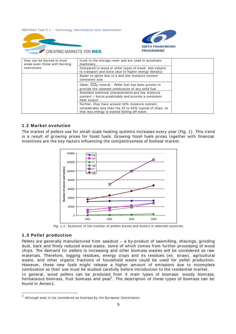
1.2 Market evolution The market of pellets use for small-scale heating systems increases every year (Fig. 1). This trend is a result of growing prices for fossil fuels. Growing fossil fuels prices together with financial incentives are the key factors influencing the competitiveness of bioheat market.
0
20000
40000
60000
80000
100000
120000
140000
2001 2002 2003 2004
Nu
mb
er o
f st
ove
s an
d b
oile
rs
DKATFIDEITSE
Fig. 1.1: Evolution of the number of pellets stoves and boilers in selected countries
1.3 Pellet production Pellets are generally manufactured from sawdust – a by-product of sawmilling, shavings, grinding dust, bark and finely reduced wood waste, some of which comes from further processing of wood chips. The demand for pellets is increasing and other biomass wastes will be considered as raw materials. Therefore, logging residues, energy crops and its residues (ex. straw), agricultural waste, and other organic fractions of household waste could be used for pellet production. However, these new fuels might release a higher amount of emissions due to incomplete combustion so their use must be studied carefully before introduction to the residential market. In general, wood pellets can be produced from 4 main types of biomass: woody biomass, herbaceous biomass, fruit biomass and peat2. The description of these types of biomass can be found in Annex1.
2 Although peat is not considered as biomass by the European Commission.

RESTMAC Task 5.1 - Technology identification and classification
6
Production chain By products from wood processing industries (sawdust, shavings and grindings) go through three main stages of pellet production: storing and pretreatment of raw materials, drying the raw material and actual pellet production process. The overall process is pictured bellow:
Raw material use Mechanical handling (palletizing, hipping, crushing, briquetting
1.4 Pellet distribution After pellets are produced, they can be delivered in 3 ways to the small heating systems (Fig. 1.5). Pellets can be packed either into 15 or 20 kg bags and distributed to the special shops where the customers can buy it at any time, packed into economy size bags of 500-1000 kg or transported loose by trucks and blown into the storage room by a special pump (picture 1.4).
Fig. 1.3: Before distribution: pellet storage deck Fig. 1.4: Pellet feeding by a special pump
Pellet plant
Bulk sales according to weight Direct
Delivery
Economysize bag500-1000 kg
Sacks Bulk
20 kg bagin pallet
Economysize bags
Distribution storage
Retailer
Transportation of raw material
Raw materialstorage
M/S Wood pellets
Export of pellets
Raw materialstorage
Sawmill orplaning mill
Fig. 1.5 Pellet production and distribution
Fig. 1.2: Pellet production process

RESTMAC Task 5.1 - Technology identification and classification
7
1.5 Pellet burning technology In the small heating systems, houses can mainly be heated either by pellet stoves (picture 1.6) or pellet boilers (picture 1.7).
Pellet stoves are more efficient, cleaner burning, and easier to use than conventional wood burning appliances. Pellet stoves are usually placed in the living area and has an esthetic value whereas pellet boilers in the non -living area of the house. Usually, the efficiency of the pellet stoves and boilers reaches 90% (Fig.1.8).
1.6 Pellet standards The European Committee of Standardisation (CEN) has prepared 30 technical specifications on solid biofuels. The standards can be used as tools to enable both efficient trading of biofuels and good understanding between seller and buyer, as well as in communication with equipment manufacturers. The following specifications have been published and available from national standardisation institutions: Terminology – CEN/TS 14588; Fuel specification and classes – CEN/TS 1461; Calorific value – CEN/TS 14918; Moisture content – 3 different (CEN/TS14774-1, 14774-2 and 14774-3); Ash content – CEN/TS 14775.
Figure 1.6: Pellet stove Figure 1.7 : Pellet boiler
Fig. 1.8: Efficiency of wood boilers for domestic use

RESTMAC Task 5.1 - Technology identification and classification
8
These technical specifications are prestandards, which are in force for 3 years after publishing. At the moment, they do not invalidate national standards. After three year period it will be decided wheather these technical specifications will be updated to EN-standards. CEN committee prepared the specifications of properties for Pellets that can be found in Annex 1. The example for high quality wood pellets recommended for household usage is as follows: Origin Chemically untreated tree without bark Moisture content M10 (Moisture < 10 w-%) Mechanical durability
DU97.5 (97.5 w-% of pellet batch of 100g shall be uncrushed after testing)
Percentage of fines F1.0 or F2.0 (percentage of fines among pellets sieved through < 3.15 mm sieve shall not exceed 1 or 2 w-% at factory gate)
Dimensions D06 or D08 (pellet diameter 6mm±0.5mm and length < 5x diameter or diameter 8±0.5mm, and length < 4x diameter). Maximum 20 w-% of the pellets may have a length of 7.5 x Diameter.
Ash content A0.7 (<0.7 w-% of dry matter) Sulphur content S0.05(<0.05 w-% of dry matter) Additives <2 w-% of dry matter may consist of bio-based chemically untreated
material, the type and amount to be given. Net calorific value E4.7 [kWh/kg] (net calorific value > 4.7 kWh/kg=16.9 MJ/kg)
2. NEW DEDICATED ENERGY CROPS FOR SOLID BIOFUELS The resources from European forestry and by-products from wood industry are not sufficient to meet the objective of the EU for solid biofuels, especially if we opt for second generation biofuels. In the long term, bioenergy crops from agriculture provide a significant potential for the biomass supply. The environmentally-compatible bioenergy potential from agriculture can reach up to 142 Mtoe by 2030 compared to 47 in 2010 (EEA report). Such a development will occur if the high yield crops are introduced, additional productivity is increased; and further liberalization of agricultural market is in place. Europe needs to promote new dedicated energy crops for energy production. It would enable the EU to diversify its energy sources, provide financial support for European farmers and reduce CO2 emissions as the energy crops are CO2 neutral. Target groups: farmers, farmer's organisations, manufacturers of technology suitable to plant and harvest new dedicated crops, heating power plants, pellet producers, national, regional and local governmental bodies responsible for agricultural matters, renewable energies and incentives for energy crops, project developers.
2.1 Energy crops characteristics The best biomass crops for energy production is one that can be harvested dry and has a perennial growth habit (no need for annual planting or tillage) to minimize cultivation costs. Low input of fertilizers and other chemicals when growing these plants helps to improve the energy efficiency. It is also important that plants can convert solar energy efficiently. Two major pathways of photosynthesis are the C3 and C4 pathway. In general, the C3 assimilation path is
Fig. 1.9: Standards of high quality wood pellets recommended for household usage

RESTMAC Task 5.1 - Technology identification and classification
9
adapted to operate under low temperature (15-20°C) whereas C4 metabolic pathway3 species are more efficient converters in high light level and high temperature situations. Tropical grasses, such as sugar cane, maize, also miscanthus and sweet sorghum are C4 plants. C4 plants can generate a theoretical maximum dry matter yield of 55 t/ha year compared with 33
t/ha from normal C3 temperate crops. However, C4 plants can only generate such a yield under hot climate conditions. In temperate climate C3 plants might be more suitable. For example, short rotation forestry suitable for energy production under temperate climate is mostly C3 species – willow, poplar, etc. In order to determine suitability of energy crops to grow them in a chosen area, the following factors should be considered: the energy balance, agronomic factors such as crop yields, soils and climate, energy output per hectare and effective utilization of all of the components of the crop at the processing stage. Calorific value, amount of ash the plants produce when used as well as their moisture content are of a crucial importance for energy production. Generally, the C4 crops such as Miscanthus are more suitable for arable lands whereas C3 crops can be grown on marginal land. In order to make the crop growing process environmentally friendly, a transportation distance should be as short as possible and should not exceed 40 km.
2.2 Conversion The primary product, in this case straw, energy cereals, Miscanthus, Poplar, Willow are converted to solid biuofuels in the form of briquettes, pellets, bales using compaction technology and then can be used for electricity and heating purposes. There are three types of plants that are suitable for conversion into solid biofuels:
• annual plant species such as cereals, , hemp, kenaf, and reed canary grass (whole plants); • perennial species harvested annually, such as Miscanthus and other reeds; • fast-growing tree varieties like poplar, aspen or willow with a perennial harvest rhythm
(short rotation or cutting cycle), short rotation coppice (SRC).
3 C4 - plant that prefaces the Calvin Cycle with reactions that incorporate CO2 into 4-carbon compound. C4 plants have a distinctive leaf anatomy. This pathway is found mostly in hot regions with intense sunlight.
Production of solid biofuels
Annual energy crops
Perennial energy crops
Energy cerelas Whole crop utilisation
Hemp Perennial grasses Fast growing trees
Triticale
Rye
Wheat
Barley
Miscanthus
Reed canary grass
Poplar
Willow
Eucalyptus
Fig. 2.1 Division of Selected Energy Crops into Groups
RESTMAC Task 5.1 - Technology identification and classification
10
2.3 Crop residues - Straw Crop residues (cobs, stems, leaves, in particularly straw and other plant matter) left in agricultural fields after harvest could potentially be used for solid biofuels production. Due to high energy content, straw is one of the best crop residues for solid biofuels. Its energy content is of 17-18 MJ per kg dry matter. However, straw has several disadvantages – it has a higher ash content, which results in lower calorific value. In order to improve its bulk density, the straw is generally baled before transportation. Straw burning requires a specific technology. There are four basic types of straw burners: those that accept shredded, loose straw; burners that use densified straw products such as pellets, briquettes or cubes and straw logs; small, square bale burners and round bale burners. To be suitable for heat and electricity production straw should not have a large content of moisture, preferably not more than 20% as the moisture reduces the boiler efficiency. Also straw colour as well as straw chemistry should be considered before burning as it indicates the quality of the straw.
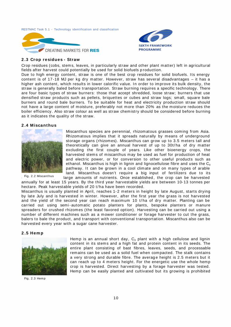
2.4 Miscanthus Miscanthus species are perennial, rhizomatous grasses coming from Asia. Rhizomatous implies that it spreads naturally by means of underground storage organs (rhizomes). Miscanthus can grow up to 3.5 meters tall and theoretically can give an annual harvest of up to 30t/ha of dry matter excluding the first couple of years. Like other bioenergy crops, the harvested stems of miscanthus may be used as fuel for production of heat and electric power, or for conversion to other useful products such as ethanol. Miscanthus is high in lignin and lignocellulose fibre and uses the C4 pathway. It can be grown in a cool climate and on many types of arable land. Miscanthus doesn’t require a big input of fertilizers due to its
capability to recycle large amounts of nutrients. Once established, the crop can be harvested annually for at least 15 years. By the third year harvestable yields are between 10-13 tonnes per hectare. Peak harvestable yields of 20 t/ha have been recorded. Miscanthus is usually planted in April, reaches 1-2 meters in height by late August, starts drying by late July and is harvested in winter. However, after the first year the grass is not harvested and the yield of the second year can reach maximum 10 t/ha of dry matter. Planting can be carried out using semi-automatic potato planters for plants, bespoke planters or manure spreaders for crushed rhizomes (the least favored option). Harvesting can be carried out using a number of different machines such as a mower conditioner or forage harvester to cut the grass, balers to bale the product, and transport with conventional transportation. Miscanthus also can be harvested every year with a sugar cane harvester.
2.5 Hemp Hemp is an annual short day, C3 plant with a high cellulose and lignin content in its stems and a high fat and protein content in its seeds. The entire plant consisting of bast fibres, leaves, seeds, and processable remains can be used as a solid fuel when compacted. The stalk contains a very strong and durable fibre. The average height is 2.5 meters but it can reach up to 4 meters height. For the energetic use the whole hemp crop is harvested. Direct harvesting by a forage harvester was tested. Hemp can be easily planted and cultivated but its growing is prohibited
Fig. 2.2 Miscanthus
Fig. 2.3 Hemp

RESTMAC Task 5.1 - Technology identification and classification
11
in some EU countries as it can be used as a drug4. The plants vegetative period is about 100 days, with the main growth period in June and July, followed by flowering in August. The yields are high (18 t/ha) but the high plant moisture content can create storage -roblems. Two different harvesting technologies are available for the energy use of the whole hemp crop. The first is the whole-fibre-technology where, with a modified chopping technology, the hemp culm is cut into 50 to 60 cm lengths. The straw stays for four weeks on the field for drying before the bales are pressed. Another technology is wet harvesting. This technology includes the chopping of the crops followed by silaging. For combustion it is necessary to press the hemp silage into bales to reduce the water content of the fuel.
2.6 Short rotation coppice (SRC): willow and poplar SRC is densely planted, high yielding varieties such as willow and poplar. It is harvested on a 2 to 5 year cycle, although commonly every 3 years. Willow and poplar are well adapted to cool climates and tolerate temporary wet conditions better than most of other species. The harvesting of the wood takes place at the vegetative rest (November to February). At this time of the year the wood has a water content of around 50 %. Performance of SRC depends on the selection of species, environmental conditions, fertilizers, soil etc. and can reach up to 20 t/ha. However, usually yield ranges from 5 to 15 t/ha of dry matter.
Harvesting can be carried out using 3 main methods: the coppice is cut and bundled in bundles; the coppice is cut and chipped in a single operation, then blown into a trailer; and an intermediate system where the coppice is cut into billets and blown into a trailer. SRF can be harvested with chopper machinery, called a chopper harvester. But conventional machineries are not really adapted for harvesting SRC as its diameter is quite big. Nevertheless there are promising developments in Denmark. A plantation could be viable for up to 30 years before re-planting becomes necessary, although the yield decreases after 5-6 rotations.
2.7 Giant Reed Giant reed is a wild plant growing in southern Europe regions. Although Giant Reed grows best in a warm climate, certain genotypes can be adapted to cooler climates and can be grown in countries like Germany or the UK. Giant Reed is one of the most productive crops as its yield reaches more than 30t/ha5 of dry matter as well as one of the most cost-effective energy crops because it is perennial with low annual inputs after establishment of the crop. The annual input consists of harvesting, irrigation and/or fertilization costs. Giant reed is one of the largest grass species that can be grown in cool temperatures and it can grow up to 5 meters tall and 3.5 cm in diameter. Giant Reed is usually harvested
either in autumn or in a late winter. Though harvesting in late winter can result in losses of the crop yield (leaves and tops are usually lost). Depending on its use, it is either harvested each year or every second year. 4 Hemp usually contains 8-12 % of delta-9-tetrahydrocannabinol (THC). For THC to be used as a drug THC needs to be present at over 2%. For this reason, the cultivation oh hemp is prohibited in some EU countries and in others only the hemp with a rate of less that 2% of THC is grown. 5 This yield can only be reached in Southern Europe.
Fig. 2.5 Poplar
Fig. 2.4 Willow
Fig. 2.6 Giant Reed
RESTMAC Task 5.1 - Technology identification and classification
12
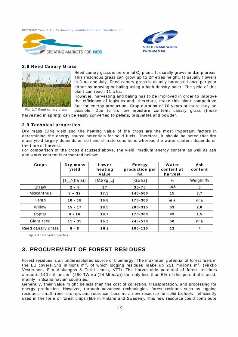
2.8 Reed Canary Grass Reed canary grass is perennial C3 plant. It usually grows in damp areas. This rhizonous grass can grow up to 2metres height. It usually flowers in June and July. Reed canary grass is usually harvested once per year either by mowing or baling using a high density baler. The yield of this plant can reach 11 t/ha. However, harvesting and baling has to be improved in order to improve the efficiency of logistics and, therefore, make this plant competitive fuel for energy production. Crop duration of 10 years or more may be possible. Due to its low moisture content, canary grass (those
harvested in spring) can be easily converted to pellets, briquettes and powder.
2.9 Technical properties Dry mass (DM) yield and the heating value of the crops are the most important factors in determining the energy source potentials for solid fuels. Therefore, it should be noted that dry mass yield largely depends on soil and climate conditions whereas the water content depends on the time of harvest. For comparison of the crops discussed above, the yield, medium energy content as well as ash and water content is presented bellow:
Dry mass yield
Lower heating value
Energy production per
ha
Water content at
harvest
Ash content
Crops
[tDM/(ha a)] [MJ/kgDM] [GJ/ha] % Weight %
Straw 2 - 4 17 35-70 14.5 5
Miscanthus 8 – 32 17,5 140-560 15 3.7
Hemp 10 - 18 16.8 170-300 n/a n/a
Willow 15 - 17 18.5 280-315 53 2.0
Poplar 9 - 16 18.7 170-300 49 1.5
Giant reed 15 - 35 16.3 245-570 50 n/a
Reed canary grass 6 - 8 16.3 100-130 13 4
3. PROCUREMENT OF FOREST RESIDUES Forest residues is an underexploited source of bioenergy. The maximum potential of forest fuels in the EU covers 543 millions m3, of which logging residues make up 251 millions m3. (Pirkko Vesterinen, Eija Alakangas & Terhi Lensu, VTT). The harvestable potential of forest residues amounts 140 millions m3 (280 TWh/a (24 Mtoe/a)) but only less than 5% of this potential is used, mainly in Scandinavian countries. Generally, their value might be less than the cost of collection, transportation, and processing for energy production. However, through advanced technologies, forest residues such as logging residues, small trees, stumps and roots can become a new resource for solid biofuels - efficiently used in the form of forest chips (like in Finland and Sweden). This new resource could contribute
Fig. 2.7 Reed canary grass
Fig. 2.8 Technical properties

RESTMAC Task 5.1 - Technology identification and classification
13
to BAP goals and avoid possible environmental problems. But the right technology is a key element here as otherwise the cost of collection becomes higher than resource itself and environmental impact is not reduced as the technology can produce secondary residues, which requires careful management. Target groups: forest owners, managers of forest land, manufacturers of forest residues harvesting technology, local entrepreneurs who carries out harvesting and transportation operations, Central heating and power plants, national, regional and local governmental bodies responsible for the forestry matters, project developers.
3.1 Types and Technology Forest fuel can be collected from young stands, short rotation forests thinnings and from final fellings - so called logging residues including harvesting the stumps and roots.
3.1.1 Forest residues from thinnings Young forests sometimes get too dense. Thinning these forests helps the trees to grow into more valuable and better quality forest. The fining process can be carried out manually or automatically with wood collectors. The whole tree received from the thinning consists of a small diameter stand wood, branches, leaves and needles and provides a significant energy potential for solid biofuels. Industrial wood parts are harvested at the same time for a better productivity.
Thinning technology - Accumulative Felling head Beside a simple wood harvester, a new technology is available such as accumulative felling head adapted to harvest young tress from early thinnings. The accumulation principle is a part of this technology which enables one to cut and bundle several trees at once and in a standing position instead of having to lay them on the ground. Depending on the tree species, up to ten trees can be accumulated before the “felling head” needs to be emptied. This increases harvesting capacity as well as harvesting efficiency due to lesser maneuver moves.
3.1.2 Forest residues from final fellings Logging residues or so called forest slash are either a waste left on the ground after the logging operations have taken place (wood harvesting) or the excesses of production that have not been used. In most countries forest slash is still not used whereas in Finland, Sweden and a couple of other countries this energy resource is largely utilised. These residues are the main source of forest fuels from final fellings. At the felling areas for every m3 of solid industrial wood, the residual biomass generated amounts from 35 to 45 %. Forest slash mainly consist of the tops of trunks, stems, branches, leaves, stumps and roots and when discharged can cause environmental problems and the loss of a natural resource. Logging residues can be effectively used with a new bundling technology. Bundling Technology for logging residues In the bundling method the forest residue or slash is collected and fed into the bundler that produces compact slash logs or bundles. The length of slash logs is approximately 3 meters and about 60-70 cm in diameter. They weight about 550 kg and kept tight with a cord. Each bundle contains about 1MWh of energy depending of species and moisture content. The machine picks up the tops and branches and places them into the feed mechanism. One hectare felling area yields about 100 -150 bundles with a productivity rate of 20 to 30 bundles per
Fig. 3.1: Timberjack harvester with Accumulative felling head

RESTMAC Task 5.1 - Technology identification and classification
14
hour (in Sweden and Finland). The length of the bundle is optimized so that the load capacity of the transport equipment can be fully utilised .
After being bundled, the slash logs are transported with
standard forwarders from the forest to the road side where they can be stored temporarily or transported to the power plant by standard timber trucks. The slash logs are usually crashed at the power plant or terminal inventory. When comparing bundles and loose residues from the stand-point of transport, bundles is the most cost effective alternative but not for short distances.
3.1.3 Forest residues from stumps and roots Stumps and roots are a major unexploited resource of forest logging residues. It consist more that 20 % of a harvestable dry mass of a tree. In regeneration cuttings the full yield from stumps has turned to be as high as from above ground residues. The stump harvesting, handling and crushing
technology is becoming cost competitive and the quality of these chips meets the requirements set for fluidized bed boilers. Silvicultural works related to removing stumps are becoming easier to handle and cost-effective. Stump and root technology Stumps are pulled using excavators equipped with a special stump rake. Wheeled stump harwarders,
which carry out both uprooting and off-road transport. When pulled, the stumps are torn to pieces – to make them clean and dry – and piled up in the harvesting area. When the stumps are dry, they are hauled to road-side storage with a heavy forest tractor. Rain and further drying improve the quality of the stumps, and they are typically kept in storage for at least a year. Long-distance transport Stump and root harvesting (chipping at plant method) is done using special trucks.
3.2 Production chain Forest residues can be divided into several procedures which is harvesting, chipping, crashing and transportation. Efficient transportation is a key element as the highest cost of the process lies in transportation. For this reason it is very important to ensure a good logistical planning and high technology navigation systems.
3.2.1 Harvesting Harvesting is the first step in the logistical chain of the production of solid biofuels. There is 67 M m3 of available forest residues in the EU member states but only 6 M m3 is harvested. The thermal value of the logging residues collected within the rotation period of wood is about 160 MWh which in thermal value corresponds to 14 tons of domestic heating oil. Logging residues can be harvested either immediately after felling or during the summer season. In seasoned case a significant part of residues are left in the felling area but the quality of wood
Fig. 3.3 Stump and root harvesting
Fig. 3.2 Bundling technology

RESTMAC Task 5.1 - Technology identification and classification
15
fuels is higher due to a lower content of moisture. Also the harvesting technology in the seasoned case is easier to manage especially in northern countries of the EU. Recovery of logging residues can reach 75- 85% in winter (Sweden and Finland) and about 45 % in summer. Recovery also depends on the chosen site to harvest, more precisely on tree species, the amount of timber, the size and branchiness of a tree. For example, spruce stands the amount of logging residues is much bigger than that for pine or birch stands. Although, a part of residues, usually 20-30%, should be left on the ground for fertilizing purposes. If the recovery rate is significantly lower than 50%, it means that the site has been poorly chosen or the work on the site has been careless. A good harvesting site (Alakangas et al, 1999):
• As much spruce as possible; good recovery rate and productivity, • Enough fertile soils only • A sufficiently large felling site or a concentration of stands, • Easily traversed, well bearing ground, • No undergrowth which hinders logging, • Short terrain transport distance • A spacious roadside storage area for long distance transport.
3.2.2 Production chain and comminution types The position of the chipper or the crusher in whole production chain determines the state of the biomass during transportaion and also a key factor influencing the transportation costs. The main chain of chip procurement is: cutting, off road transport from forest site to road site, comminution, secondary transport from roadside to mill, and receiving and handling at the plant (Hakkila, 2004). The most important phase is comminution as it has a crucial fact of the cost efficiency. Before combustion, the forest residues are comminuted, that is chipped or crashed. The comminution can take place in terrain, at landing, at terminal or at plant.
Comminution in terrain Terrain chipping is based on a single machine, called terrain chipper. Terrain chippers carry out several operations. It lifts the residues with its grapple loader and puts them into the feeder of the chopping device; residues then are chipped and hauled into a container to the landing or to the roadside. The truck picks up the exchangeable containers and transports them to the power plant and returns the emptied containers to the landing.
This type of communition is economically viable in small logging sites because the single machine carries out a communition of residues and the off-road transport of chips, so the cost of shifting machines from site to site is reduced. However, the capacity of load is rather small, the speed of the chipper is low and the operations require flat and even ground. For these reasons the role of terrain chipper in large scale production is diminishing.
Comminution at roadside or landing The communition at landing is the traditional option for forest chip production. Logging residues are hauled by forwarders to the roadside landing all year round from the surroundings of the terminal and bunched into 4-5 metres piles. They are left to dry over the next summer which improves the quality of the fuel.
3.4 Comminution in terrain

RESTMAC Task 5.1 - Technology identification and classification
16
The forwarder operates independently of the chipper and logging residues are chipped directly to the long distance trailer trucks without any storage of forest residue chips at the landing. Depending on the size of operation, either farm tractors that drive the chipper (small-scale operations) or heavy truck mountain crushers or chippers (large-scale operations) are used. Therefore, this communition type results in waiting and stockages as there is a close
linkage between chipper and truck when the chips are blown directly into the trailer trucks. However landing chippers do not operate off road and can therefore be heavier, stronger and more efficient than terrain chippers. If the biomass such as stump and root wood is contaminated by stones and soil, it is also possible to use crushers that are more tolerant than chippers.
Comminution at terminal Comminution at terminal is based on the following subsequent phases: terrain haulage, storage and drying. The residues are transported to a centralized terminal where they are chipped later. At the terminal, the uncomminuted residues are unloaded into a storage deck where they are left to dry over summer. The terminal stores of logging residues are typically 400 to 2000 m3 (in Sweden and Finland). If compared with
comminution at landing or road side the terminal method enables more economical storage and chipping as well as easier quality control. Comminution at plant In the comminution at plant, the logging residues are chipped and crashed at the end use facility. Either loose or in bundles, residues are transported to the plant where a chipper or crasher performs the chipping. This method improves the fuel quality as well as the control of the procurement process. Also, heavy stationary crashers at a plant can comminute a wide variety of biomass including stump, root and recycled wood. Comminution at plant can be implemented more economically than in terrain or roadside and the operations are often carried out by local entrepreneurs.
4. COGENERATION AT SMALL SCALE The EU Directive 2004/8/EC “on the promotion of cogeneration based on a useful heat demand in the internal energy market” obliges member states to conduct analysis of the potential of high efficiency cogeneration in their country and to establish a support system to encourage cogeneration. It is of obvious relevance to the development of cogeneration, however, it is still
3.5 Comminution at roadside or landing
3.6 Comminution at terminal
3.7 Comminution at plant

RESTMAC Task 5.1 - Technology identification and classification
17
early days. Whether it be small-scale <1 MWe or micro-scale below <50kWe, the directive states it is necessary to ensure high efficiency for any new capacity. The directive clarifies high efficiency in such that it “must provide primary energy savings of at least 10 % compared with the references for separate production of heat and electricity.” Cogeneration, the simultaneous production of electricity and heat, from biomass is seen as one of the best means of converting a sometimes expensive fuel into heat and power. This is due to the higher efficiencies gained from producing electricity and importantly - securing the by-product, heat, for use in district heating systems or for individual homes. Biomass has the advantage of being carbon neutral, which contributes to curbing CO2 emissions in line with the Kyoto protocol targets. Of particular interest to possible cogeneration operators is the existence of governmental measures such as subsidies and green certificates. In Germany they grant 0.02 Euros/kWhe if it is produced from a biomass sourced gas, which is added on top of the normal RE (renewable energy) remuneration (Cogen Europe, Feb 2005).
4.1 Applications – Target User The target consumer for small and micro CHP (Combined Heat and Power) technology includes a whole host of clients. It largely depends on the requirements of the user and the costs involved. The most common applications are in small residential buildings (or single homes for micro-cogeneration), swimming pools, leisure facilities, greenhouses, small industries, hospitals and industrial laundries where there is a constant demand for heat. Careful analysis of the potential to use both the electricity and the heat must be made. If they cannot be used on-site, then study needs to be done to see if the energy can be exported either to the national grid in the case of electricity or to the local area in the case of heat. There is particular suitability of cogeneration in the urban residential sector as the cost of electricity from the grid used for heating is often expensive (Knight and Ugursal, 2005).
4.2 Cogeneration Technologies One has to concede that the installation of cogeneration units can be quite complicated. One has to conduct a feasibility study on a case by case basis to work out the best technology and capacity for the building. There are a number of different cogeneration technologies, some of which are suitable for biomass fuelling. The main technologies for cogeneration units are: the reciprocated internal combustion engine (R-ICE), gas engine, gas turbine, microturbine, heating oil engine, steam turbine, Stirling engine and Fuel Cell. All are compatible with biofuels except the R-ICE and the heating oil engine.
4.3 Best Biomass Options for Future Cogeneration A technology specifically suited for biomass cogeneration, still in relatively early stages of commercialisation, is the “gasification” of wood-based biomass. It takes place in an oxygen starved state and is converted into wood gas which is then combusted. Although only a number of pilot plants have been build, one favoured technology is the gas engine. This is seen as a most promising CHP technology considering the relative abundance of wood, especially wood waste from forestry and agriculture industries in Europe. Another type of cogeneration system, called fluidized bed combustion, is also proving extremely interesting for biomass fuelling. In this system one often combusts a variety of fuels such as wood chips, sawdust and sometimes a fraction of fossil fuel like coal. One particular example, comes from Finland, which is home to the largest biomass plant in the world at Jakobstad (West Finland) run by Alholmens Kraft Ab, which uses a circulated fluidized bed boiler (CFB) burning wood waste, peat and coal. Using a steam turbine it provides 240 MWe, along with 100 kWth process steam for a nearby paper mill and 60 MWth for district heating. This is obviously above small scale CHP but it highlights state of the art

RESTMAC Task 5.1 - Technology identification and classification
18
technology used today. At the moment downsizing of these technologies to small scale is proving difficult in terms of efficiency.
4.4 Reciprocated Internal Combustion Engines and Gas Engines This type of engine is one of the most established technologies - used since the beginning of motorised transport. They can also be used in a stationary mode to produce heat and power. In a reciprocated internal combustion engine, the fuel is ignited (either petroleum or diesel) and the hot gases expand pushing the piston down creating mechanical movement, and that in turn is linked to a generator to produce electricity. The heat from this combustion is captured from the exhaust gases, cooling water and engine oil, producing the thermal energy for the building. The main advantages of this technology are low capital and operational cost, reliable onsite energy, ease of maintenance and wide service infrastructure (Knight and Ugursal, 2005). The disadvantages are that they produce relatively high levels of emissions, such as Nitrous oxides, Sulphur dioxide, Carbon monoxide as well as particulate matter, and VOCs (Volatile Organic Compounds). The majority of combustion engine units for CHP purposes are in fact a modified version of the R-ICE called the gas engine, where it uses gaseous fuel such as natural gas instead of liquid petrol. Natural gas is easier to transport and cleaner to combust. Gas engines have a typical capacity range of 500kWe to 40MWe, therefore most are above the 1 MWe Commission defined threshold for small CHP. There are a large number of CHP units available already from the likes of Tecogen (USA) who offer a range of units from 65-100 Kwe R-ICE units (see Figure 4.1 and 4.2) and Cummins Inc. who offer R-ICE cogeneration systems in the range of 7.5-1750 kW which runs on diesel or natural gas, suitable for family or residential purposes. Honda, on the other hand, have produced an extremely compact R-ICE cogeneration unit of 1 kWe and 3 kWth which runs at high efficiency (85%) and is especially suitable for meeting base load requirements as well as for back-up. It will be available for purchase in the autumn of 2006.
An example of a gas engine comes from Biomass Engineering Ltd. who built a pilot biomass-fuelled CHP plant at Rainford, in the UK. The project took place from 2003 to 2005 and it has a capacity of 250 kWe with a heat recovery of 100-500 kWth with a 15 minute start-up time. It is based on gasification of woody biomass into a “producer gas” (mostly methane and CO), which can then be combusted in a gas engine (see Figure 4.3). And from there, there is a standard connection to a generator to convert it into electricity. Efficiency was rated at around 34%. Costing was estimated at 3.5 pence/ kWh (5.1 cents €) without the feedstock and 5.7 pence/kWh (8.3 cents €) with a feedstock of £25/tonne (36 €). This cost would drop if one can sell heat energy at the same time.
4.5 Gas Turbines and Microturbines Another technology suitable for CHP, is the gas turbine and it’s smaller brother, the microturbine. It has advantages over the modern internal combustion engine, such as its high power density,
Fig. 4.3 – IVECO Gas Engine HMSO, PSI Licence: C2006010726
Fig. 4.1 - TECOGEN R-ICE cogeneration unit Copyright of TECOGEN
Fig. 4.2 - engine block of the CHP Unit

RESTMAC Task 5.1 - Technology identification and classification
19
fewer moving parts and extremely low emissions. They can be fuelled by liquid and gaseous fuels - fossil or renewable. Gas Turbine capacity is generally between 500 kW and 250 MW and microturbines generally range from 30 to 350 kW. It is possible to use biogas (landfill, sewage, anaerobically digested, etc.) and waste gases (flare gases from refineries, industries) as fuels. However, the chemical composition of much of these alternatives requires pre-treatment due to contaminants in the biomass which effects the operation of the turbine. Kawasaki, a large American gas turbine manufacturer, offers a version of their M1A 13X, 0.61 MWe gas turbine (see immediate right) with a catalytic combustor producing less than 3 ppm NOx guaranteed. A 65 kW microturbine (see Figure 4.5) is available from Capstone Turbines (USA) which can use biogas as fuel and can achieve 29 % electrical efficiency and 62 % overall efficiency. A COGEN study looked into the financial possibilities for a cogeneration unit in Portugal, where a 30 kW micro CHP unit would be installed in a hotel. The report says it will save 17 tonnes of CO2 per year as well as over 11,000 Euros in electricity bills. There is also the option to export electricity back to the grid.
4.6 Stirling Engines
The Stirling Engine is still seen as an emergent technology in the realm of CHP systems, thus still expensive, despite the origins coming from the 19th century. It works with heat from an external heat source brought via a heat exchanger. The heat from the heat exchanger is put into contact with the operating gas in the cylinder of the stirling engine, where it expands at high temperature driving the piston up. This system reduces the complexity of the engine compared to an ICE and thus increases reliability and reduces maintenance. The advantage of an external heat source is that it can be powered by biomass solar, wind, or fossil fuels. This flexibility and the high efficiency of the engine means there is great opportunity ahead. Costs have to be reduced to become commercially competitive with other CHP technologies but there are some models already on the market. Many regard stirling engines as one to watch for the future.
Microgen from the United Kingdom has developed one of the first small scale CHP units for individual homes (see Figure 4.6) to replace the traditional boiler. The unit is reported to be small and quiet enough to be mounted in the kitchen. It has 1.1 kWe and 15-36 kWth (which can be modulated down to 5 kW). It is designed to take natural gas as the fuel, and a petroleum version is in the pipeline. Overall efficiency is rated at 90%. Of particular interest is Solo, a German company who are developing a biomass fuelled Stirling 161 CHP unit. Currently they have natural gas or liquid gas fuelled models. It is targeted for homes and small businesses. The capacity is based around a modulating unit of 2-9.5 kWe and 8-26 kWth. Overall efficiency is between 92 and 96%.
4.6 Steam Turbine A steam turbine works by the combustion of a fuel in a boiler, which heats up water- injected air that gets pressurised during combustion forming steam which is fed into the steam turbine. The
Fig. 4.6 – Cross section Stirling Engine Copyright of Microgen Energy Limited
Fig. 4.5: Microturbine Copyright of Capstone Turbines
Fig. 4.4: Gas Turbine Copyright of Kawasaki Gas Turbine Europe

RESTMAC Task 5.1 - Technology identification and classification
20
turbine is then fed to the generator. Typically steam turbines have a lower electrical efficiency than gas turbines or a reciprocated engine but overall efficiency can be higher. Applications for steam turbines are those that require a high heat to power ratio and they are more suited to medium to large scale industrial uses such in metal and paper industries which often operate continuously and have a high demand for steam. They are not seriously considered for small cogeneration application.
4.8 Fuel Cells An additional option for cogeneration include Fuel Cells as they are the most emission friendly option discussed, whereby hydrogen is combined with oxygen from the air to produce electrical energy, with water vapour and heat as by-products. A hydrogen source is the largest problem, as traditional methods include the electrolysis of water (costly) and reforming of fossil fuels. Many are understandably sceptical of fuel cell power as it is only as clean as it’s source and hydrogen is still largely derived from the steam reforming of natural gas. In some fuel cell types such as Ceramic fuel cells, one can purchase a fuel cell reformer to utilise all sorts of other fuels, such as propane, butane and biodiesel or ethanol. The disadvantages of fuel cells are its relatively high cost, their short life span and regular replacement of components is necessary. The most appropriate applications for fuel cells include residential, small scale commercial and institutional uses due to the low emissions and noise levels. Acumentrics, an American fuel cell manufacturer, has developed a Solid Oxide Fuel Cells (SOFC), designed for CHP use, rated at 10kWe, 4kWth. There are many fuel options: natural gas, methane, propane, ethanol, methanol and hydrogen. Electrical efficiency is rated at between 40-50% and 75% overall based on a Lower Heating Value (LHV). An important advantage of the Acumentrics SOFC is that they allow direct injection of the various fuels rather than having to reform it, thus allowing renewable fuelling from bioethanol. There are negligible SO2 and NOx emissions but there is a 10-30 minute warm-up wait before electricity is available. Other manufacturers include Valiant (Germany), Sulzer Hexis (Switzerland), Sigen (UK), Proton Motor (Germany), Phocos (Germany), Nuvera (USA and Italy), Ceramic Fuel Cells (Australia), Electrocell Group (Brazil) and Plug Power (USA).
5. BIOETHANOL PRODUCTION AND USE In recent years, largely in response to uncertain fuel supply and efforts to reduce carbon dioxide emissions, bioethanol has become one of the most interesting biofuels to be considered as a feasible alternative to fossil fuels in Europe. The current EU commitment under Directive 2003/30/EC on the promotion of the use of biofuels or other altenative fuels for transport set a guideline for biofuels to account for 5.75% of all transport fuels by 2010. In the 1970s, Brazil and the USA started mass production of bioethanol - grown from sugarcane and corn respectively. Smaller scale production started more recently in Spain, France and Sweden mostly from wheat and sugar beet. Bioethanol is seen as a good alternative because the source crops can be grown renewably in most climates around the world. In addition the use of bioethanol, largely as a transport fuel, is CO2 neutral. In recent years the concept of the bio-refinery has emerged, whereby one integrates biomass conversion processes and technology to produce a variety of products including fuels, power, and chemicals. In this manner one can take advantage of the natural differences in the chemical and structural composition of biomass. There are associated economic benefits for such bio-refineries where one could, for example, produce bioethanol primarily but also sell pellets or feed for animals produced from the waste part of the plant. The

RESTMAC Task 5.1 - Technology identification and classification
21
Commission document “An EU Stategy for Biofuels” reports that along the Seventh Framework Programme (FP7) it will give high priority support into research for the “bio-refinery” concept.
5.1 Bioethanol Production The production of bioethanol from traditional means comes from starch crops like corn, wheat and cassava and from sugar crops like sugar cane and sugar beet. However, the cultivation of alternative crops from sweet sorghum opens up new possibilities in Europe, especially in hotter and drier regions such as Southern and Eastern Europe. In addition to this, the development of lignocellulosic technology has meant that not only high energy content starch and sugar crops can be used but also woody biomass or waste residues from forestry. This development is seen as the 2nd Generation of Biofuels. This process is still expensive by comparison to traditional bioethanol production, as it requires an additional pretreatment process of pulping and a more complex “cocktail” of enzymes to break down the organic compounds. Depending on the biomass source the steps generally include:
1. Storage 2. Cane crushing and juice extraction 3. Dilution 4. Hydrolysis for starch and woody biomass 5. Fermentation
From there, the bioethanol will be transported, distributed and sold in a similar manner to normal transport fuels. The following table shows some examples of the manufacturers of the different technologies needed for a bioethanol plant. However, the complexity of a bioethanol plant is considerable and it therefore requires dedicated planning and expertise to build one, so the majority of bioethanol plants are built upon specification by a contracted engineering company (specialising in bioethanol), rather than by purchasing individual component units. Firms that provide such a service include Vogelbusch GMBH (Austria), Lurgi (Germany), GEA Wiegand (Germany), Chematur Engineering (Sweden) Bayer Technology Services (Germany), TECNIA (Portugal), Delta- T Corp. (USA), Praj Industries (India).
Technology Type Name Country Technology Type Name Country
Bagasse Driers A.H. Korthof B.V. NL Enzymes Genencor International Inc US
SRI - Sugar Research International AU Novozymes A/S DK
Sugarequip (Pty) Ltd. SA Fermentation Chemel AB SE
Cane Milling Plant Fives Cail FR Genencor International Inc US
Fletcher Smith Limited UK Novozymes A/S DK
Techserve C.C. SA Juice Purification Systems GEA Filtration US
Control Systems BMA (Braunschwelgishe Maschinenbauanstalt AG) DE H. Putsch GmbH & Comp. KG DE
Dresser-Rand Company US SRI - Sugar Research International AU
Beet Diffusers BWS Technologie GmbH DE Storage Vessels H. Putsch GmbH & Comp. KG DE
Fives Cail FR Miedemal/Uninge Holland B.V. NL
Fletcher Smith Limited UK Waste Water Treatment GEA Filtration US
Distillation Technology TD Chemicals PTY Limited AU H. Putsch GmbH & Comp. KG DE
6. CO2 storage and ethanol recapture 7. Distillation 8. Waste water treatment 9. Fuel Storage
Table 5.1: Ethanol Industry Technology Suppliers

RESTMAC Task 5.1 - Technology identification and classification
22
Table 5.2: Largest European bioethanol producers:
5.2 By-products in Bioethanol Production Additional steps that may be taken in a biorefinery include the drying and pelletisation of bagasse (the waste component of sugar cane after juice extraction) to produce a secondary product along with ethanol, which makes the plant more economically feasible. In addition to the production of fuel pellets, one can also produce feed for animals, which could be used locally thereby reducing CO2 emissions from associated transport energy spent. Although, the drying phase of bagasse is slightly different from that of wood biomass, the pelletiser technology is the same for all biomass. Pelletiser manufacturers include: Kahl GmbH & Co. (Germany), Bühler AG (Switzerland), MÜNCH Edelstahl GmbH (Germany), Promill Stolz (France), Andritz Deurne AG (Netherlands), Synergia OZE (Poland) (see right), RADMAR (Poland), Costruzioni Nazzareno (Italy), La Meccanica (Italy). Even though there are increased costs associated with lingo-cellulosic material, there are also possible benefits. Development of new ways of separating the organic compound lignin in the woody biomass has begun in the pursuit of value-added lignin based products. One such company producing lignin based products is Borregaard LignoTech (Norway and USA), who have developed a large range of pro -ducts for agricultural chemicals – binder or dispersants, ceramics, emulsion stabilizers for oil, asphalt or wax, mining & extraction, fertilizers and dust suppression products. There are even possibilities for the production of industrial chemicals and bio-plastics from woody biomass (Mabee and Sadler, 2006).
Producer Country Capacity (litres/yr)
Saint-Louis Sucre France 15,000,000
C Union France 120,000,000
Tereos France 50,000,000
Südzucker Germany 260,000,000
Sauter Germany 310,000,000
Kwst Germany 30,000,000
Abengoa Bioenergy Spain 510,000,000
Agroethanol AB Sweden 50,000,000
Svensk Ethanolkemi Sweden 100,000,000
Fig. 5.2 Pellet Mill Copyright of Synergia OZ
Figure 5.1: Bioethanol Plant Südzucker Bioethanol, based in Mannheim, Germany supplies E85 grade bioethanol from their recently commissioned plant (Feb 2006) at Zeitz (see right) which cost 200 million euros. It produces 260 million litres of bioethanol a year from high value protein feed, mostly wheat.
Copyright of Südsucker

RESTMAC Task 5.1 - Technology identification and classification
23
5.3 Target User and Bioethanol Use The uses for bioethanol have typically been as a biofuel for transport, especially in Brazil. Therefore, energy companies are one target group. In addition supermarkets who provide petrol stations to customers are seeing the opportunity to provide petrol/ethanol blends from 5-85% (E5 –E85). Even though most experts agree that up to a 10% mix will not damage modern car engines, the manufacturer warranty for standard cars is set at 5%. Above this level, the car engines need to be modified or one has to buy a fuel flexible vehicle (FFV). Sweden is arguably the strongest in the bioethanol transport market with over
500 E85 (SEKAB, 2006) pump stations and 15,000 Ford Focus FFVs have been sold there since it’s debut on the market in 2001. By May 2006, 15% of all newly sold cars were either bioethanol or biogas fueled. E85 is being sold at prices substantially less than petrol, between 75 and 85 € cents per litre compared to 1.11 € and 1.19 € for petrol. Elsewhere in Europe, there are at present 40 bioethanol petrol stations in Germany serving E50, E85 or E100. The UK supermarket chain TESCO has already 200 stations in the UK supplying B5 (5% bioethanol blended with standard unleaded petrol). Morrisons Supermarket supply a higher blend of bioethanol - E85, available from 5 forecourts in the South of England (see Fig. 5.3- showing a Ford Focus) marketed at 2 pence below petrol. However, their bioethanol is supplied from Futura Petroleums, which all comes from Brazilian fuel stocks. The consumer is the most important target user concerning bioethanol. Their opinion will largely dictate market development.
5.3.1 Vehicles The Ford Focus FFV (see Fig. 5.5) has been marketed at a price slightly higher than the basic petrol model. The commercial potential of the car has received a boost by the Avon and Somerset (UK) Police who bought 15 of the fuel flexible Focus’ in March 2006. Further interest has been shown by other regional police forces throughout the United Kingdom. The advantage is that they are still able to refuel from petrol at any percentage, thus not limiting their range to where the bioethanol pump infrastructure does not reach. Ford reports there is a 70% reduction in CO2 emissions compared the petrol version. The Focus FFV , and Focus C-MAX although released in September 2005, it is still yet to be released to the dealerships on a large scale. Swedish car marker, Volvo, has two models that run on bioethanol, those being the S40 (see opposite) and V50. Neither of them are, as yet, widely available in the UK or France. Saab’s has a 9-5 biofuel saloon and estate model that can run on E85. There are a small number of these biopower models available at selected dealerships in the South and East of England, one notably in Norfolk, where there is a small E85 fuel pump infrastructure via the Morrisons supermarket chain. Saab has only this year produced a bio-hybrid electric engine that will work on E100, first shown at the Stockholm motor show and based on the Saab 9-3 model.
Fig. 5.5: Ford Focus FFV Copyright of Ford Motor Company
Fig. 5.3: E85 Pump station, Copyright of Morrisons PLC
Fig. 5.4: S40 FFV Volvo Copyright of Volvo

RESTMAC Task 5.1 - Technology identification and classification
24
5.3.2 Chemicals An additional use of bioethanol is in the chemical industry - as a feedstock, where already many large sugar based firms supply ethanol for cosmetics, spirits, varnish, vinegar, coatings, adhesives, sanitisers and other medical applications. There are a large number of different fuel grades of ethanol, each being suitable for a specific use. The traditional source for feedstocks are from the petrochemical sector. We now have the opportunity to produce them in a renewable fashion from biomass.
5.3.3 Fuel Cells Typically fuel cells function by combining hydrogen with oxygen from the air to produce electrical energy, with water vapour and heat as by-products. Fuel Cells have a typical electrical efficiency of between 30 and 60 % and an overall efficiency, if using the heat by-product, of 70-90 %. The units run with very low noise emissions and pollutant gas emissions are also reduced considerably. It’s disadvantages are its relatively high cost, their short life span (regular replacement of components). A number of fuel cells can use bioethanol as well as fossil fuels without the need for a reformer (to convert it to hydrogen). Acumentrics (USA) and Ceramic Fuel Cells (Australia) manufacture such fuel cells.

RESTMAC Task 5.1 - Technology identification and classification
25
REFERENCES
1. PELLETS FOR SMALL - SCALE DOMESTIC HEATING SYSTEMS Figure 1.1- Evolution of the number of pellets stoves and boilers in selected countries; source: www.pelletcentre.info/CMS/site.asp?p=953 Figure 1.2 - Pellet production process; source: K. P. Nemestothy, E.V.A., Wood fuels: characteristics, standards, production technology, the Austrian Energy Agency, 2004, http://www.bioheat.info/pdf/kpn_wood_fuels_at.pdf Figure 1.3 - Before distribution: pellet storage deck; source: AEBIOM Figure 1.4 - Pellet feeding by a special pump: P.A.Araman, R.J. Bush, V.Tech, “Wood pellets, research points to potential urban pellets materials”, http://www.forestprod.org/smallwood06araman2.pdf Figure 1.5 - Pellet production and distribution, source: VTT Figure 1.6 - Pellet stove; source : AEBIOM Figure 1.7 - Pellet boiler ; source : AEBIOM Figure 1.8 - Efficiency of wood boilers for domestic use; source: K. P. Nemestothy, Wood fuels: characteristics, standards, production technology, the Austrian Energy Agency, E.V.A., 2004, http://www.bioheat.info/pdf/kpn_wood_fuels_at.pdf Figure 1.9 - Standarts of high quality wood pellets recommended for household usage; source: E. Alakangas, CEN Technical Specification for Solid biofuels – Fuel Specification and Classes and Fuel Quality Assurance, VTT
2. NEW DEDICATED ENERGY CROPS FOR SOLID BIOFUELS Figure 2.1 - Division of Selected Energy Crops into Groups, source: Energy from Biomass Course Figure 2.2 – Miscanthus, source: http://www.silsoe.cranfield.ac.uk/iwe/expertise/energycrops.htm Figure 2.3 – Hemp, source: http://www.hempreport.com/gallery/melfort/pictures/dcp_0814.html Figure 2.4 – Willow, source: http://www.judyarndt.ca/galleries/flora_fauna/image/willow.jpg Figure 2.5 – Poplar, source: http://www.llnl.gov/pao/news/news_releases/2006/images/poplar284x426.jpg Figure 2.6 – Giant Reed, source: http://en.wikipedia.org/wiki/Arundo_donax Figure 2.7 – Reed Canary Grass, source: http://www.vapo.fi/eng/biofuels/energy_crops/reed_canary_grass/?id=982 Figure 2.8 – Technical properties, sources: Agricultural biomass in EU25, source: www.biorefineryworkshop.com/presentations/Panouts ou2.pdf Lars D. Fenger ([email protected]), Combustion of miscanthus and other biofuels in a full scale CHP plant, Energy E2 A/S; Straw for Energy production, Technology – Environment - Economy, The centre of Biomass Technology, 19992; Jurgen Maier @ Reinhold Vetter, Biomass yield and fuel caracteristics of short-rotation coppice (willow, poplar, empress tree), 2004; Nils-Erik Nordh and Ioannis Dimitriou, Harvest Techniques in Europe, 2003; N.El Bassam: Energy Plant species: their use and impact on environment and development, 1998; G.Termeer and A.P.C. Faaij, Multi-product crops – case study for Poland and the Netherlands
3. PROCUREMENT OF FOREST RESIDUES Figure 3.1 – Timberjack harvester with accumulative felling head, source: P.Hakkila, VTT processes, Developing technology for large scale production of forest chips, 2004 Figure 3.2 - Bundling technology, source: K. P. Nemestothy, E.V.A., Wood fuels: characteristics, standards, production technology, the Austrian Energy Agency, 2004, http://www.bioheat.info/pdf/kpn_wood_fuels_at.pdf

RESTMAC Task 5.1 - Technology identification and classification
26
Figure 3.3 - Stump and root harvesting, VTT Figure 3.4 - Comminution in terrain, source: VTT Figure 3.5 - Comminution at roadside or landing, source: VTT Figure 3.6 - Comminution at terminal, source: VTT Figure 3.7 - Comminution at plant, source: VTT
4. COGENERATION AT SMALL SCALE Figure 4.1 – TECOGEN 65 kWe cogeneration unit, Copyright of TECOGEN, source: www.tecogen.com/pdf/cogen4pg.pdf Figure 4.2 – TECOGEN engine block of the cogeneration unit, Copyright of TECOGEN, source: www.tecogen.com/pdf/cogen4pg.pdf Figure 4.3 - IVECO Gas Engine, from report: Development of a 250 kWe Downdraft Gasifier for CHP, DTI (Department of Trade and Industry), Project Summary No PS251, Licence to reproduce authorised by HMSO, PSI Licence: C2006010726, source: http://reporting.dti.gov.uk/cgi-bin/rr.cgi/http://www.dti.gov.uk/files/file 30546.pdf?nourl=www.dti.gov.uk/publications/pdflink/&pubpdfdload=06%2F1365 Figure 4.4 - Gas Turbine Copyright of Kawasaki Gas Turbine Europe, source: http://www.kawasaki-gasturbine.de/en/i_e06gpc.htm Figure 4.5 - Microturbine Copyright of Capstone Turbines, source: http://www.capstoneturbine.com/_docs/PDS_RenewableCR65&CR65_ICHP1R.pdf Figure 4.6 - Cross section Stirling Engine, Copyright of Microgen Energy Limited, source: http://www.microgen.com/micro_CHP.asp Cogen Europe (February 2005), EU Biomass Action Plan: The need to prioritise cogeneration, Position Statement, http://www.cogen.org/Downloadables/Publications/Position_Paper_Biomass _Action_Plan.pdf Knight, I. and Ugursal, I. (June 2005), Residential Cogeneration Systems: A Review of The Current Technologies, A Report of Subtask A of FC+COGEN-SIM The Simulation of Building-Integrated Fuel Cell and Other Cogeneration Systems
5. BIOETHANOL PRODUCTION AND USE Figure 5.1 –Bioethanol Plant at Zeitz, Copyright Südsucker, source: http://www.suedzucker.de/_downloads/ pressebilder/72dpi/bioethanolzeitz72.zip Figure 5.2 - Pellet Mill, Copyright of Synergia OZ, source: http://www.synergia.pl/console/ img/1/6_granulator.jpg Figure 5.3 - E85 Pump station, Copyright of Morrisons PLC, source: image provided by Gary Bolton, Press Officer (South, Midlands and Wales) Wm. Morrison Supermarkets PLC Tel: +44 (0)845 611 Ext: 5362 Figure 5.4 - S40 FFV Volvo Copyright of Volvo, source: http://www.media.volvocars.com, section Photo Archive, Car models, image reference number: P2006_1471 Volvo S40 FlexiFuel Figure 5.5 - Ford Focus FFV Copyright of Ford Motor Company, source: http://www.ford.co.uk/ns7/corporate_news/-/news_focusflexifuel Table 5.1 - Ethanol Industry Technology Suppliers, Sugar Industry Buyers Guide, Spring 2006 Table 5.2 - Largest European bioethanol producers, Abengoa Bioenergy (Spain), 2006, source: http://www.abengoabioenergy.com/bioethanol/index.cfm?page=7&loc=2 Mabee, W.E. and Saddler, J.N. (April 2006). Ethanol from Lignocellulosics: Comparing biofuel technology options. IEA Task 39 Report T39-P4
RESTMAC Task 5.1 - Technology identification and classification
27
ANNEX 1
Description of biomass types suitable for pellet production
Wood pellets can be produced from 4 main types of biomass: woody biomass, herbaceous biomass, fruit biomass and peat6:
• Woody biomass – biomass from trees, bushes and shrubs. Forest wood, wood processing industry residues, fibre board residues, particle board residues, plywood residues, and used wood.
• Herbaceous biomass – biomass from plants with a non -woody stem which die back at the end of the growing season.
• Fruit biomass – biomass from fruits, for example berries, nuts and the residues from fruit processing industry.
• Peat – decomposed material which has accumulated in water-logged conditions. A substantial proportion consists of dead organic, plant-based matter. It is a slowly renewable natural resource for which there are many uses, particularly in energy and horticulture. The carbon content and calorific value, particularly those of high decomposed peat, make pet suitable for use in energy. Also, the cellular structure, low pH and low nutrient status, particularly those of slightly decomposed sphagnum peat, make peat suitable for use in horticultural growing media.
6 Although peat is not considered as biomass by the European Commission.

RESTMAC Task 5.1 - Technology identification and classification
28
ANNEX 2
Specifications of pellets properties
Master table Origin: According table 1 in CEN/TS 14961
Woody Biomass (1) Herbaceous biomass (2), Fruit biomass (3) Blends and mixtures (4)
Traded form Pellets Dimensions (mm) See Figure 2 Diameter (D) and Length (L)* D06 D08 D10 D12 D25
= 6 mm ± 0,5 mm and L = 5 × Diameter = 8 mm ± 0,5 mm and L = 4 × Diameter = 10 mm ± 0,5 mm and L = 4 × Diameter = 12 mm ± 1,0 mm and L = 4 × Diameter = 25 mm ± 1,0 mm and L = 4 × Diameter
Moisture (w-% as received) M10 M15 M20
= 10 % = 15 % = 20 %
Ash (w- % of dry basis) A0.7 A1.5 A3.0 A6.0 A6.0+
= 0.7 % = 1.5 % = 3.0 % = 6.0 % = 6.0 % (actual value to be stated)
Sulphur (w-% of dry basis) S0.05 S0.08 S0.10 S0.20+
= 0.05 % = 0.08 % = 0.10 % = 0.20 % (actual value to be stated)
Sulphur is normat ive only for chemically treated biomass and if sulphur containing additioves have been used
Mechanical durability (w- % of pellets after testing) DU97.5 DU95.5 DU90.0
= 97.5 % = 95.0 % = 90.0 %
Amount of fines (w-%, < 3.15 mm) after production at factory gatea F1.0 F2.0 F2.0+
= 1.0 % = 2.0 % > 2.0 % (actual value to be stated)
At the last possible place in the production site
Additives (w-% of pressing mass) Type and content of pressing aids, slagging inhibitors or any other additives have to be stated Nitrogen, V (w-% of dry basis)
No
rma
tive
NO.3 NO.5 N1.0 N3.0 N3.0+
= 0.3 % = 0.5 % = 1.0 % = 3.0 % > 3.0 % (actual value to be stated)
Nitrogen is normative only for chemically treated biomass
Net calorific value, qp,net,ar (MJ/kg as received) or energy density, Ear (kWh/ m3 loose)
Recommended to be informed by retailer
Bulk density as received (kg/ m3 loose) Recommended to be stated if traded by volume basis
Info
rmati
ve
Chlorine, CI (weight of dry basis, w-%) Recommended to be stated as a category CI 0.03, CI 0.07 CI 0.10, CI 0.10+ (if CI >0.10% the actual value to be stated)
*NOTE: Maximum 20 w-% of the pellets may have a length of 7,5 × Diameter