Response to RFP for - SYSCOM · CICS ADMINISTRATION ... specific information in the table below to...
63
400 East Pratt Street Baltimore, Maryland 21202-3116 (410) 539-3737 AIS+ EE Advanced Image Solution+ Enterprise Edition Version 1.0 Client Toolkit Installation and Systems Programmer Guide
-
Upload
nguyenkhanh -
Category
Documents
-
view
216 -
download
0
Transcript of Response to RFP for - SYSCOM · CICS ADMINISTRATION ... specific information in the table below to...

400 East Pratt Street Baltimore, Maryland 21202-3116
(410) 539-3737
AIS+ EE
Advanced Image Solution+ Enterprise
Edition Version 1.0
Client Toolkit
Installation and Systems Programmer Guide
AIS+ EE 1.0 Client Toolkit Installation and Systems Programmer Guide
Syscom, Inc. Page 1 6/1/01
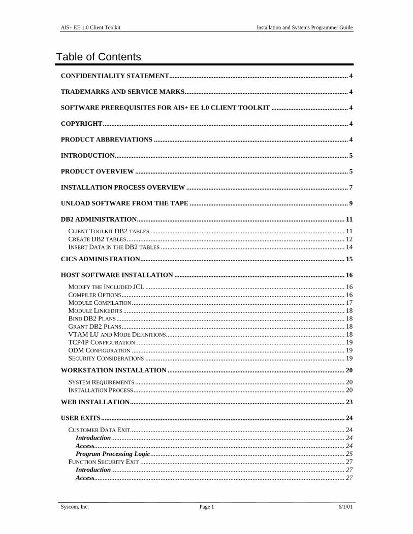
Table of Contents CONFIDENTIALITY STATEMENT......................................................................................................... 4
TRADEMARKS AND SERVICE MARKS................................................................................................ 4
SOFTWARE PREREQUISITES FOR AIS+ EE 1.0 CLIENT TOOLKIT ............................................. 4
COPYRIGHT................................................................................................................................................ 4
PRODUCT ABBREVIATIONS .................................................................................................................. 4
INTRODUCTION......................................................................................................................................... 5
PRODUCT OVERVIEW ............................................................................................................................. 5
INSTALLATION PROCESS OVERVIEW ............................................................................................... 7
UNLOAD SOFTWARE FROM THE TAPE ............................................................................................. 9
DB2 ADMINISTRATION.......................................................................................................................... 11
CLIENT TOOLKIT DB2 TABLES .................................................................................................................. 11 CREATE DB2 TABLES................................................................................................................................ 12 INSERT DATA IN THE DB2 TABLES ............................................................................................................ 14
CICS ADMINISTRATION........................................................................................................................ 15
HOST SOFTWARE INSTALLATION .................................................................................................... 16
MODIFY THE INCLUDED JCL ..................................................................................................................... 16 COMPILER OPTIONS................................................................................................................................... 16 MODULE COMPILATION............................................................................................................................. 17 MODULE LINKEDITS .................................................................................................................................. 18 BIND DB2 PLANS...................................................................................................................................... 18 GRANT DB2 PLANS................................................................................................................................... 18 VTAM LU AND MODE DEFINITIONS......................................................................................................... 18 TCP/IP CONFIGURATION........................................................................................................................... 19 ODM CONFIGURATION ............................................................................................................................. 19 SECURITY CONSIDERATIONS ..................................................................................................................... 19
WORKSTATION INSTALLATION ........................................................................................................ 20
SYSTEM REQUIREMENTS ........................................................................................................................... 20 INSTALLATION PROCESS............................................................................................................................ 20
WEB INSTALLATION.............................................................................................................................. 23
USER EXITS............................................................................................................................................... 24
CUSTOMER DATA EXIT.............................................................................................................................. 24 Introduction......................................................................................................................................... 24 Access................................................................................................................................................... 24 Program Processing Logic.................................................................................................................. 25
FUNCTION SECURITY EXIT ........................................................................................................................ 27 Introduction......................................................................................................................................... 27 Access................................................................................................................................................... 27

AIS+ EE 1.0 Client Toolkit Installation and Systems Programmer Guide
Syscom, Inc. Page 2 6/1/01
Program Processing Logic.................................................................................................................. 27 Parameter List Structure..................................................................................................................... 28
PREFETCH EXIT ......................................................................................................................................... 30 Introduction......................................................................................................................................... 30 Access................................................................................................................................................... 30 Program Processing Logic.................................................................................................................. 30 Parameter List Structure..................................................................................................................... 31
DELETE OBJECT EXIT................................................................................................................................ 32 Introduction......................................................................................................................................... 32 Access................................................................................................................................................... 32 Program Processing Logic.................................................................................................................. 32 Parameter List Structure..................................................................................................................... 33
VALIDATE DATA EXIT ............................................................................................................................... 35 Introduction......................................................................................................................................... 35 Access................................................................................................................................................... 35 Program Processing Logic.................................................................................................................. 35 Parameter List Structure..................................................................................................................... 37
OPERATOR ADMINISTRATION SECURITY EXIT ........................................................................................... 41 Introduction......................................................................................................................................... 41 Access................................................................................................................................................... 41 Program Processing Logic.................................................................................................................. 41 Parameter List Structure..................................................................................................................... 42
WORK FLOW EXIT..................................................................................................................................... 43 Introduction......................................................................................................................................... 43 Access................................................................................................................................................... 43 Program Processing Logic.................................................................................................................. 43 Parameter List Structure..................................................................................................................... 44
APPENDIX A: PROGRAM LIST............................................................................................................. 45
CICS MODULES..................................................................................................................................... 45
APPENDIX B: DB2 ARCHITECTURE................................................................................................... 46
DATABASE INFORMATION ......................................................................................................................... 46 DB2 PLAN................................................................................................................................................. 47 DB2 TABLE X-REF ................................................................................................................................... 47 FLXAPPL - APPLICATION PROFILE........................................................................................................... 49 FLXCOLL – COLLECTION/FORM ............................................................................................................. 49 FLXDCMT – DOCUMENT PROFILE .......................................................................................................... 49 FLXDLOG – DELETE/UNDELETE LOG..................................................................................................... 49 FLXDRSN – DELETE/UNDELETE REASON............................................................................................... 49 FLXDTAB – DEFAULT FOLDER TABS...................................................................................................... 49 FLXELOG - ERROR LOG.......................................................................................................................... 50 FLXEXIT - USER DATA EXITS ................................................................................................................. 51 FLXFLDR - FOLDER PROFILE .................................................................................................................. 53 FLXGOPR - OPERATOR GROUP ASSIGNMENT ......................................................................................... 53 FLXGRUP - FORM GROUP PROFILE ......................................................................................................... 53 FLXMSGS - MESSAGES ........................................................................................................................... 53 FLXOPAS - OPERATOR ASSIGNMENT (FOR WORKFLOW) ....................................................................... 53 FLXOPPF - OPERATOR PROFILE .............................................................................................................. 53 FLXPROG - PROGRAM FUNCTIONCODES ................................................................................................ 54 FLXRLTT – RLOB/TRANSACTION TYPE................................................................................................. 55 FLXTABS - FOLDER TABS....................................................................................................................... 55 FLXTRAN - CICS TRANSACTION IDS ..................................................................................................... 55 FLXUNIT – UNIT CODE (FOR WORKFLOW) ............................................................................................ 55

AIS+ EE 1.0 Client Toolkit Installation and Systems Programmer Guide
Syscom, Inc. Page 3 6/1/01
FLXUNRC – UNIT/ROUTE CODE (FOR WORKFLOW) .............................................................................. 55 FLXWORK – WORK DETAIL (FOR WORKFLOW) .................................................................................... 55
APPENDIX C: ERROR MESSAGES....................................................................................................... 56
APPENDIX F: VTAM AND CICS SETUP .............................................................................................. 60
VTAM EXAMPLE...................................................................................................................................... 60 CICS FAF REGION.................................................................................................................................... 61

AIS+ EE 1.0 Client Toolkit Installation and Systems Programmer Guide
Syscom, Inc. Page 4 6/1/01
Confidentiality Statement
This document contains proprietary information and must therefore remain confidential among SYSCOM, Inc. and Customers who have executed the AIS+ software license agreement.
Trademarks and Service Marks
The following terms used in this publication are registered trademarks or service marks of the IBM Corporation in the United States or other countries:
CICS DB2 OS/390
TSO ImagePlus FAF
ISPF IODM FWA
Software Prerequisites for AIS+ EE 1.0 Client Toolkit
The following software components and release levels are required for the AIS+ Client Toolkit: • OS/390 2.8 or higher • Transaction Server 1.3 or higher • DB2 6.1 or higher • Content Manager ImagePlus 3.1 or higher • AIS+ front end application
Copyright
The entire contents of this manual are copyright 1999, 2001 by SYSCOM, Inc. All rights reserved.
Product Abbreviations The following is an approved abbreviation for the Syscom AIS+ Enterprise Edition product name used in this publication and the full product name to which the abbreviation refers:
AIS+ Is an abbreviation for Syscom AIS+ Enterprise Edition
AIS+ EE Is an abbreviation for Syscom AIS+ Enterprise Edition

AIS+ EE 1.0 Client Toolkit Installation and Systems Programmer Guide
Syscom, Inc. Page 5 6/1/01
Introduction
Welcome to SYSCOM's AIS+ EE 1.0 Client Toolkit software. This manual will guide you through the installation and verification process.
The Client Toolkit provides a set of API’s that integrate with ImagePlus and FAF. Communications to the mainframe are accomplished via TCP/IP or APPC over SNA.
Product Overview
The Client Toolkit provides the following workstation API’s:
• Document List: Returns a list of documents based on the arguments passed from the workstation API (i.e., Folder ID, Document Type, Tab Name, Start Date, End Date).
• Folder List: Returns a list of folders, based on full or partial primary and secondary index values passed from the workstation API.
• Folder Note List: Returns a list of folder notes based on the arguments passed from the workstation API (i.e., Folder ID, Start Date and Time, End Date and Time).
• Folder Note View: Returns a folder note based on the folder note information passed from the workstation API (i.e., Note Time Stamp).
• Folder Note Add: Adds a folder note to the FAF application based on the information passed from the workstation API (i.e., Short Description, Note Text).
• Folder Note Delete: Deletes a folder note based on the information passed from the workstation API (i.e., Note Time Stamp).
• Note List: Returns a list of folder notes based on the arguments passed from the workstation API (i.e., Folder ID, Start Date and Time, End Date and Time).
• Document View: Displays the documents selected from Document List or based on the passed values from the workstation API (i.e., Folder ID, Document Type, Tab Name, Start Date, End Date).
• Document Print: Prints the documents selected from Document List or based on the passed values from the workstation API (i.e., Folder ID, Document Type, Tab Name, Start Date, End Date).
• Document Fax: Fax documents selected from the Document List.
• Folder Update: Updates the folder primary index and secondary indexes based on the information passed from the workstation API (i.e., Folder ID, Secondary Index 1 (one), Secondary Index 2 (two) and Secondary Index 3 (three) ).
• Document Copy/Move: Copies or moves a document from one folder to another based on the document information passed from the workstation API.
• Document Delete/UnDelete: Deletes or undeletes (if applicable) a document from one folder based on the document information passed from the workstation API.

AIS+ EE 1.0 Client Toolkit Installation and Systems Programmer Guide
Syscom, Inc. Page 6 6/1/01
• Get Work: Provides the ability to present document(s) to the operator that has been assigned to work on them. The documents are presented for one Folder ID at a time.
• List Queue: Allows for the list of queued items for a particular route unit, folder ID, operator assigned, or route code.
• Work Management: Provides workflow functions for a document or a batch of documents such as route, hold, assign, un-assign, and drop.
• Operator Assignment: Provides the ability to add or remove work queues (route code/unit code) for a given operator.
• Document History: Allows for the viewing of history events associated with a document.
• Document Modify: Allows for the modification and update of object specific fields such as Receive Date, Priority, Security Class, Object Description, and routing data.
• Operator Profile: Provides the ability to add new operators to your application, modify profiles of existing operators and delete operators which are no longer needed.
• Form Profile: Provides the functions that enable you to view, update or add a form profile.

AIS+ EE 1.0 Client Toolkit Installation and Systems Programmer Guide
Syscom, Inc. Page 7 6/1/01
Installation Process Overview
There is certain site-specific information (i.e. system libraries, DB2 authorities, data set naming standards) that you will need to have available during the installation process. Write your site-specific information in the table below to use as a reference throughout the installation process.
JCL Parameter Description Your Company’s Value
AIS+ EE SOURCE LIBRARY For Client Toolkit source members
AIS+ EE OBJECT LIBRARY For Client Toolkit Object modules.
AIS+ EE CICS LOAD LIBRARY For Client Toolkit CICS load modules.
AIS+ EE COPY LIBRARY For Client Toolkit Copybook modules.
AIS+ EE BATCH LOAD LIBRARY For Client Toolkit Batch load modules.
AIS+ EE DBRM LIBRARY For Client Toolkit DBRM modules.
AIS+ EE INSTALL BASE LIBRARY For Client Toolkit install modules.
DB2 LOAD LIBRARY Your DB2 load library that contains DB2's IKJEFT01 program
DB2 RUNTIME LIBRARY Your DB2 runtime library. If the library is concatenated in the system link, then this entry is not required.
DB2 DBRM LIBRARY Your DB2 system DBRM library
DB2 SUBSYSTEM ID The 4 character DB2 subsystem ID Client Toolkit will be running under
DB2 VERSION The DB2 version Client Toolkit will be running under
VCAT CATALOG The catalog Client Toolkit will be running under
SQL OWNER ID The DB2 administrative owner in building the Client Toolkit database and associated components
STOGROUP NAME (DATA) The storage group that will contain the Client Toolkit DB2 data
STOGROUP NAME (INDEX) The storage group that will contain the Client Toolkit DB2 indexes
STOGROUP VOLSERS (DATA) The DASD volumes used by the DATA STOGROUP
STOGROUP VOLSERS (INDEX) The DASD volumes used by the INDEX STOGROUP
DATABASE NAME The database name you will assign to Client Toolkit

AIS+ EE 1.0 Client Toolkit Installation and Systems Programmer Guide
Syscom, Inc. Page 8 6/1/01
JCL Parameter Description Your Company’s Value
FAF API VERSION The IBM FAF API version Client Toolkit will be running under
FAF DBRM LIBRARY The FAF DBRM library
FAF OWNER ID The DB2 Administrator owner used when the FAF tables were created.
Depending upon your site's policies and standards, one or more individuals may be required to install this product. The installation procedure is relatively simple and straight forward. If you are the one individual who is tasked to perform the installation, you must have the ability and authority at either the DB2 SYSADM (build everything) or DBADM (build all but the storage group) level. We will discuss this further when installing the Client Toolkit database. You will also need the ability to add new IBM CICS PPT, PCT, and RCT table entries to the Client Toolkit-targeted IBM CICS region. But foremost, you need access to IBM TSO to perform these functions.

AIS+ EE 1.0 Client Toolkit Installation and Systems Programmer Guide
Syscom, Inc. Page 9 6/1/01
Unload Software from the Tape The first file on the tape contains the installation JCL job stream to unload the tape's files into the libraries you will target to eventually hold the Client Toolkit software. The sample JCL below should be coded and run to extract the first file into a PDS member capable of being edited.
//jobname JOB (accounting),’label’,CLASS=?, // MSGCLASS=?,NOTIFY=?,REGION=? //GENER EXEC PGM=IEBGENER //SYSUT1 DD DSN=FLXEE10.UNLOAD.JCL, // DISP=OLD, // LABEL=(1,SL), // UNIT=?, // VOL=SER=FLXEE1, // DCB=(LRECL=80,RECFM=FB,BLKSIZE=3120) //SYSUT2 DD DSN=?, // DISP=?, // SPACE=?, // UNIT=?, // DCB=(RECFM=?,LRECL=?,BLKSIZE=?) //SYSIN DD DUMMY //
The installation JCL stream should now be in a position to be modified. As you will see, the stream is a lengthy, yet simple set of PROCs. The FLXLOAD JCL stream will load all members into their correct location after allocating the following datasets:
• An Installation library named FLXEE10.INSTLIB with the following characteristics:
DCB=(DSORG=PO,RECFM=FB,LRECL=80,BLKSIZE=3120) SPACE=(3120,(250,250,30),,,ROUND)
• A Copybook library named FLXEE10.CPYLIB with the following characteristics: DCB=(DSORG=PO,RECFM=FB,LRECL=80,BLKSIZE=3120) SPACE=(3120,(500,250,60),,,ROUND)
• A Source library named FLXEE10.SRCLIB with the following characteristics: DCB=(DSORG=PO,RECFM=FB,LRECL=80,BLKSIZE=3120) SPACE=(3120,(500,250,60),,,ROUND)
• A SPUFI library named FLXEE10.SPUFILIB with the following characteristics: DCB=(DSORG=PO,RECFM=FB,LRECL=80,BLKSIZE=3120) SPACE=(3120,(250,250,07),,,ROUND)
• A DBRM library named FLXEE10.DBRMLIB with the following characteristics: DCB=(DSORG=PO,RECFM=FB,LRECL=80,BLKSIZE=3120) SPACE=(3120,(500,250,50),,,ROUND)
• A Object library named FLXEE10.OBJLIB with the following characteristics: DCB=(DSORG=PO,RECFM=FB,LRECL=80,BLKSIZE=6160) SPACE=(6160,(1500,250,80),,,ROUND)
AIS+ EE 1.0 Client Toolkit Installation and Systems Programmer Guide
Syscom, Inc. Page 10 6/1/01
Please review the JCL and make any modifications necessary to conform to your site's naming conventions and standards. The bolded "FLXEE10" above is defaulted in the JCL and should be modified to conform to your sites high-level qualifier standards. If your site does not permit this form of dataset allocation, you will have to modify the 'DD' statements and space parameters accordingly.
After all of the modifications are completed, submit the FLXLOAD job and verify that each step completes with a condition code of zero (0). If a condition code other than zero is encountered, correct the problem and rerun the job. If you are building the PDSs within the job, delete and un-catalog them first, otherwise you may experience additional JCL errors upon the next execution.

AIS+ EE 1.0 Client Toolkit Installation and Systems Programmer Guide
Syscom, Inc. Page 11 6/1/01
DB2 Administration
This section assumes that the FAF API database and AIS+ EE has been fully installed. The FAF API database structure allows for multiple tablesets for some of the larger tables. If necessary, refer to the IBM SAA ImagePus Folder Application Facility MVS/ESA Application Programming Interface System Programmer's Guide for a more detailed explanation of tablesets. There are three options available to assure that the Client Toolkit takes advantage of these tablesets.
(1) Create all tablesets for the FAF API tables. For the tablesets that will not be used, you should set them up with minimal space. This is the suggested option because it only requires altering the space on the tables and indices within the tableset when creating an application with a new tableset. An additional advantage is dropping and creating synonyms or rebinding any plans will not be necessary. (2) Create only the tablesets that you will be using and create synonyms for the other tablesets. This option is best if you cannot spare the minimum space required to create all the tablesets. Unfortunately, the synonyms must point to existing tables. Therefore, there is a risk of someone setting up a test application pointing to an assumed test tableset that is really a production tableset. (3) Create only the tablesets that you will be using and specify VALIDATE(RUN) on all the binds. This option will cause all DB2 validations to occur at run time, instead of bind time, which will detrimentally affect performance.
Client Toolkit DB2 tables There are jobs and SPUFI members that need to be executed to install the Client Toolkit database architecture. These jobs should be modified to conform to your site's job card requirements and to point to the appropriate DBRM, DB2 system and application libraries. In addition, the space and bufferpool assignments must be modified to meet your application's requirements. For detailed information on the Client Toolkit tables, refer to Appendix B of this manual.
The table below lists all of the members and their functions and includes a column to check off when each task is completed (this will assure that no task is missed accidentally). Under the Job Function heading, there are also some modification issues that should be addressed for each individual member. These tasks are not designed to run parallel and must run in the sequence displayed on the chart.
After all of the modifications are completed, submit each job and verify that each step completes with a condition code of zero. You should also walk through the output to verify that all DB2 components were built correctly. Potential non-zero condition codes will appear if you are not authorized to perform all of the functions, rerun the job without first deleting the previously established database contents, or your supplied parameters are not permissible for your site's standards.

AIS+ EE 1.0 Client Toolkit Installation and Systems Programmer Guide
Syscom, Inc. Page 12 6/1/01
Create DB2 tables
NAME FUNCTION EXECUTE SUCCESSFUL (\/)
FLXVIEWS This is a SPUFILIB member that creates views for the Client Toolkit on the following AIS+ front end tables:
AIS+ Table Client Toolkit View
AISAPPL FLXAPPL
AISTRAN FLXTRAN
AISOPPF FLXOPPF
AISFLDR FLXFLDR
AISTABS FLXTABS
AISDCMT FLXDCMT
AISMSGS FLXMSGS
AISGOPR FLXGOPR
AISGRUP FLXGRUP
AISDLOG FLXDLOG
AISDRSN FLXDRSN
AISDTAB FLXDTAB
AISCOLL FLXCOLL
AISRLTT FLXRLTT
FLXVIEWW (WorkFlow)
This is a SPUFILIB member that creates FluxWorks front end tables as views on the following AIS+ front end tables:
AIS+ Table Client Toolkit View
AISWORK FLXWORK
AISUNIT FLXUNIT
AISUNRC FLXUNRC
AISOPAS FLXOPAS
BFLXELOG This job defines the tablespace, and creates the table and index for the Client Toolkit Error Log table.
BFLXEXIT Define the tablespace, and create the table and index for the Client Toolkit User Exit table. This table is created so that the FWA (IBM Folder WorkFlow Application) customers can utilize their existing user exits. An entry in the FLXEXIT table is not required for AIS+ applications, but the FLXEXIT table must be created and defined with minimal space so that the bind jobs complete successfully.
BFLXPROG Define the tablespace, and create the table and index for the Client Toolkit Program Function Codes table.

AIS+ EE 1.0 Client Toolkit Installation and Systems Programmer Guide
Syscom, Inc. Page 13 6/1/01
BFLXWKST or
VFLXWKST
If Fax Router is installed, verify that table FAXWKST has been created. If table FAXWKST exists, run SPUFILIB member VFLXWKST to create the fax server IDs table FLXFXWK as a view on table FAXWKST.
If FaxRouter is not installed or the FAXWKST table does not exist, run job BFLXWKST to create the fax server IDs table FLXFXWK.
GRANT This is a SPUFILIB member that can be used to grant access to the Client Toolkit tables.
GRANTWK
(WorkFlow)
This is a SPUFILIB member that can be used to grant access to the Client Toolkit tables for WorkFlow.
CRESYNON This is a SPUFILIB member that can be used to create SYNONYMS for the Client Toolkit tables.
CRESYNW (WorkFlow)
This is a SPUFILIB member that can be used to create SYNONYMS for the Client Toolkit tables for WorkFlow.
AIS+ EE 1.0 Client Toolkit Installation and Systems Programmer Guide
Syscom, Inc. Page 14 6/1/01
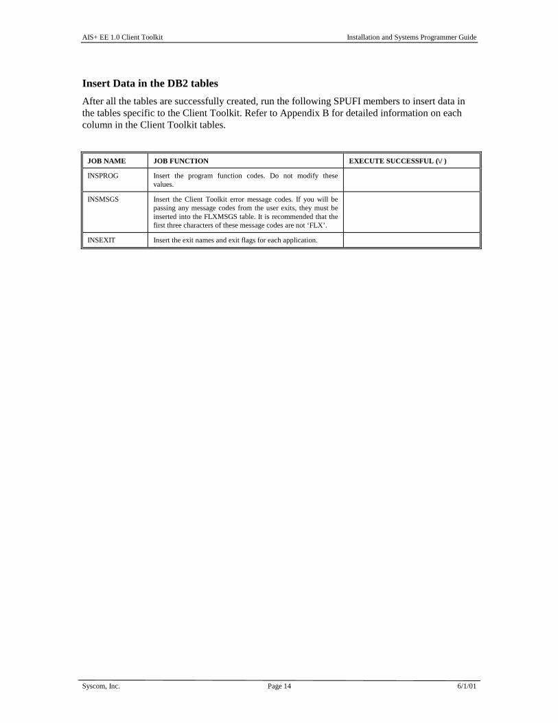
Insert Data in the DB2 tables After all the tables are successfully created, run the following SPUFI members to insert data in the tables specific to the Client Toolkit. Refer to Appendix B for detailed information on each column in the Client Toolkit tables.
JOB NAME JOB FUNCTION EXECUTE SUCCESSFUL (\/ )
INSPROG Insert the program function codes. Do not modify these values.
INSMSGS Insert the Client Toolkit error message codes. If you will be passing any message codes from the user exits, they must be inserted into the FLXMSGS table. It is recommended that the first three characters of these message codes are not ‘FLX’.
INSEXIT Insert the exit names and exit flags for each application.

AIS+ EE 1.0 Client Toolkit Installation and Systems Programmer Guide
Syscom, Inc. Page 15 6/1/01
CICS Administration
Included in your installation library are several members used to set up the AIS+ EE 1.0 Client Toolkit in your CICS region. Sample JCL is provided to load CICS definitions (includes all PPT and PCT entries for the Client Toolkit). Your communications protocol will determine the member(s) that should be used to install your PPT, PCT and RCT entries.
1. PPT and PCT Entries
In an SNA environment (APPC), use member FLXCSDAP. This member contains PPT and PCT entries for the APPC communications program, FLAPPC1P.
In a TCP/IP environment, use member FLXCSDTC. This member contains PPT and PCT entries for the TCP/IP communications program, FLTCIP1P.
In either environment, use member FLXCSDWK for workflow implementation.
2. RCT entries
In an SNA environment (APPC), use member FLXRCTA. This member creates an entry for transaction FLAP and associates it with the plan for the APPC communications program, FLAPPC1P. In a TCP/IP environment, use member FLXRCTT. This member creates an entry for transaction FLIP and associates it with the plan for the TCP/IP communications program, FLTCIP1P.
The FLXRCT* member should be included in your normal RCT stream and reassembled to include the entries required for the AIS+ Client Toolkit.
Include the Client Toolkit CICS load library in your CICS startup deck. It is recommended to install the Client Toolkit in the same region where AIS+ EE is installed.

AIS+ EE 1.0 Client Toolkit Installation and Systems Programmer Guide
Syscom, Inc. Page 16 6/1/01
Host Software Installation
Modify the Included JCL The AIS+ EE 1.0 Client Toolkit software is shipped with sample JCL to linkedit the object modules into your AIS+ load libraries. The sample JCL called LINKCICS is located in the INSTALL dataset. Modify the members to conform to your site's JCL standards, including job card requirements and references to the appropriate system and application libraries.
The sample source modules for the user exits are provided.
Compiler Options The Client Toolkit software is generated using the following compiler options:
DB2 SQL Precompiler options: • APOST • APOSTSQL • FLAG(I) • HOST(COB2) • LINECOUNT(60) • MARGINS(8,72) • ONEPASS • OPTIONS • PERIOD • NOSOURCE • STDSQL(NO) • SQL(DB2) • NOXREF
NOTE: If your installation defaults are other than ISO, please include the following precompiler options as well:
• DATE(ISO) • TIME(ISO)
IBM VS COBOL II options: • NOADV • APOST • AWO • BUFSIZE(4096) • NOCMPR2 • COMPILE • DATA(31) • NODBCS • NODECK • NODUMP • NODYNAM • NOEXIT • NOFASTSRT

AIS+ EE 1.0 Client Toolkit Installation and Systems Programmer Guide
Syscom, Inc. Page 17 6/1/01
• NOFDUMP • FLAG(I) • NOFLAGMIG • NOFLAGSAA • NOFLAGSTD • LANGUAGE(EN) • LIB • LINECOUNT(60) • NOLIST • NOMAP • NONAME • NONUMBER • NUMPROC(PFD) • OBJECT • OFFSET • NOOPTIMIZE • OUTDD(SYSOUT) • RENT • RESIDENT • SEQUENCE • SIZE(MAX) • SOURCE • SPACE(1) • NOSSRANGE • NOTERM • NOTEST • TRUNC(OPT) • NOVBREF • NOWORD • XREF(FULL) • ZWB
Link Edit Parameters: • AMODE(31) • RMODE(ANY)
Module Compilation • If user exits will be used, either modify the source stub members provided or create
copies of the members and modify them. • Submit the COMPCICS JCL stream to compile any customized exit members. This
member contains a step for DB2 precompiling, so if the user exits have DB2 access, use this job for them as well. If the user exits do not have DB2 access, make a copy of this JCL member, remove the DB2 precompile step, and submit for each of the non-DB2 exits.
.
AIS+ EE 1.0 Client Toolkit Installation and Systems Programmer Guide
Syscom, Inc. Page 18 6/1/01
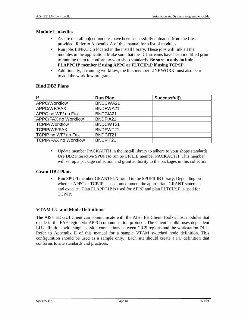
Module Linkedits • Assure that all object modules have been successfully unloaded from the files
provided. Refer to Appendix A of this manual for a list of modules. • Run jobs LINKCICS located in the install library. These jobs will link all the
modules in the application. Make sure that the JCL streams have been modified prior to running them to conform to your shop standards. Be sure to only include FLAPPC1P member if using APPC or FLTCIP1P if using TCP/IP.
• Additionally, if running workflow, the link member LINKWORK must also be run to add the workflow programs.
Bind DB2 Plans If …… Run Plan Successful() APPC/Workflow BNDCWA21 APPC/WF/FAX BNDFWA21 APPC no WF/ no Fax BNDCIA21 APPC/FAX no Workflow BNDFIA21 TCPIP/Workflow BNDCWT21 TCPIP/WF/FAX BNDFWT21 TCPIP no WF/ no Fax BNDCIT21 TCPIP/FAX no Workflow BNDFIT21
• Update member PACKAUTH in the install library to adhere to your shops standards. Use DB2 interactive SPUFI to run SPUFILIB member PACKAUTH. This member will set up a package collection and grant authority to the packages in this collection.
Grant DB2 Plans • Run SPUFI member GRANTPLN found in the SPUFILIB library. Depending on
whether APPC or TCP/IP is used, uncomment the appropriate GRANT statement and execute. Plan FLAPPC1P is used for APPC and plan FLTCIP1P is used for TCP/IP.
VTAM LU and Mode Definitions The AIS+ EE GUI Client can communicate with the AIS+ EE Client Toolkit host modules that reside in the FAF region via APPC communication protocol. The Client Toolkit uses dependent LU definitions with single session connections between CICS regions and the workstation DLL. Refer to Appendix E of this manual for a sample VTAM switched node definition. This configuration should be used as a sample only. Each site should create a PU definition that conforms to site standards and practices.

AIS+ EE 1.0 Client Toolkit Installation and Systems Programmer Guide
Syscom, Inc. Page 19 6/1/01
TCP/IP Configuration In order for the AIS+ EE GUI Client or Web Client to communicate with the AIS+ EE Client Toolkit on the host, the CICS TCP/IP Socket Interface must be configured and running in the same CICS region where ImagePlus FAF and AIS+ EE reside. Detailed instructions for installation are available in the IBM manual TCP/IP for MVS: CICS TCP/IP Socket Interface Guide and Reference. Once the installation jobs have been run, the socket configuration can be verified by running EZAC (socket configuration transaction). Three listener parameters are of particular importance to the Client Toolkit TCP/IP environment: • PORT – This represents the port number the CICS Listener will use for accepting
connections. • TRANTRN – Specify YES. Yes indicates that the transaction code from the Transaction
Initial Message should be translated from ASCII to EBCDIC. • TRANUSR - Specify YES. Yes indicates that the user data from the Transaction Initial
Message should be translated from ASCII to EBCDIC. Once installed, the TCP/IP socket startup transaction EZAO should be executed. This will bring up the CICS TCP/IP Socket Interface in the CICS region. This can be verified by running the CICS active task list command, “CEMT I TASK”, to make sure that the socket listener is up and running. The socket listener transaction, commonly known as CSKL, will be listed as a task in the task list. Please note that the configuration of the CICS TCP/IP Socket Interface should be done in both the FAF & ODM regions. See IBM’s TCP/IP for MVS: CICS TCP/IP Socket Interface Guide and Reference for more details.
ODM Configuration The IODM Workstation Configuration Table (IDWKCFTB) identifies characteristics about each image workstation associated with the Object Distribution Manager (ODM). There must be an entry in this table for each TCP/IP-connected workstation. See IBM’s ImagePlus Object Distribution Manager MVS/ESA System Programmer’s Guide for more details.
Security Considerations In a RACF environment, a universal access authority (UACC) of read must be granted for the Client Toolkit TCP/IP communications transaction, or FLIP. In tern, FLIP must have authority to access the CICS TCP/IP socket listener transaction, commonly known as CSKL. Finally, CSKL must have authority to access the transactions required to support the CICS TCP/IP Socket Interface: EZAC, EZAO and EZAP. For RACF, see IBM’s OS/390 Security Server manual for more details.

AIS+ EE 1.0 Client Toolkit Installation and Systems Programmer Guide
Syscom, Inc. Page 20 6/1/01
Workstation Installation
System Requirements 10 MB Drive Space 64 MB Memory 200Mhz or higher CPU
Installation Process Run the program x:\Setup.exe where x is the drive
location where the install program is located. A series of screens will appear to guide the user through
the installation process. Each screen is not illustrated here, only those screens that require user input.
User and Company Name When this screen appears, you can customize the user and
company information. Installation Location The next screen will ask for the installation directory for
the application. Setup Type Generally, you will want to select a Typical install. A
Typical install includes the DLLs, OCX, sample code and the Comm test application.
A Compact install will only install the DLLs and OCX file without any of the sample code.
The Custom install provides you the option of what to install with the setup. The Application group must be installed for the application to function properly.
Select Program Folder This is the last step in the installation, simply accept the
default if you want the application to go into the Fluxworks Sample group. To place the application in a different group, simply select the other group from the list and click the Next button.
Summary Screen If all of the options appear correct, press the Next button
on this screen and the application will begin its install. Once the installation is complete, the configuration program
will automatically run.

AIS+ EE 1.0 Client Toolkit Installation and Systems Programmer Guide
Syscom, Inc. Page 21 6/1/01
Configuration Program The configuration program is used to set up the
Client Toolkit registry settings so the application can function properly.
Client Toolkit Set up Tab On this tab, indicate the method of communication
with the host (either APPC or TCP/IP) and enter the workstation ID required by the ODM region to return images to the workstation. You will need your host System Administrator to provide you with this information.
TCP/IP Tab On this tab, enter the host’s IP address where
Imageplus/390 resides. Enter the port number of the ImagePlus FAF and Client Toolkit CICS region.
Enter the transaction name for the host Client Toolkit TCP/IP communication program. By default, the transaction name is FLIP.
The Remote Time Out measures the amount of seconds the Client Toolkit workstation communication program will wait for a response from the host.
APPC Tab This tab has only one field, the Symbolic
Destination Name required for the APPC communication. The symbolic destination name must match the side information table name in the APPC communication software being used: for example, WallData Rumba, Attachmate and Pcomm.
When all of the information is entered, click the Update button and the information will be updated in the registry.

AIS+ EE 1.0 Client Toolkit Installation and Systems Programmer Guide
Syscom, Inc. Page 22 6/1/01
APPC Setup Basic Side Information The SymDest Name should match the value that
was entered as the Fluxworks SDN entered on the APPC tab of the configurator.
The Partner LU Alias should match the ImagePlus FAF region on the mainframe where the Client Toolkit resides.
The Local LU is the LU assigned to the workstation for connection to the ImagePlus FAF region.
The Mode Name to be used for the VTAM connection to the mainframe.
Advanced Side Information With the exception of the Sync Level, the defaults
should be accepted. Set the Sync Level to None.
These screens are from a RUMBA configured workstation,
the user’s actual screens may differ depending upon the version and communication package used.

AIS+ EE 1.0 Client Toolkit Installation and Systems Programmer Guide
Syscom, Inc. Page 23 6/1/01
Web Installation See the AIS+ EE Web Client Installation Guide.

AIS+ EE 1.0 Client Toolkit Installation and Systems Programmer Guide
Syscom, Inc. Page 24 6/1/01
User Exits
Customer Data Exit
Introduction
The AIS+ Customer Data Exit is used to modify folder and document information based upon customer specific requirements. The customer data exit can also be used to access a folder ID with an alternate key.
Note: The format of the AIS+ Customer Data Exit copybook has been modified in AIS+ EE 1.0 to give users more flexibility in accessing data from subsequent exit calls. Therefore, you must be sure to compile your customized exit with the EE version of the copybook.
Access
The supplied sample exit (AIEX001P) is accessed by various Client Toolkit functions through the use of the CICS LINK command:
!"Document List
!"Note List
!"Note Add
!" Folder Update
!"Document Copy/Move
!"Work Management
!"Get Work
!"Document History
The customer exit name can be supplied in the Client Toolkit User Exit table (FLXEXIT). The FLXEXIT table will also contain a flag that indicates whether the front-end application is AIS+ or FWA. The value of this flag will determine the data area being passed. The flag can also be set so that the customer data exit is not called.

AIS+ EE 1.0 Client Toolkit Installation and Systems Programmer Guide
Syscom, Inc. Page 25 6/1/01
Program Processing Logic
The exit has three (3) different options that range from 0 to 2. The option will determine the information passed to the exit, the type of process to be performed, and the information to be passed back to the calling program.
OPTION CODE
DESCRIPTION
0 Determines whether the folder can be accessed. This option also permits the modification of the folder ID. The exit is called before any validations are made against the front-end tables.
1 Determines whether the folder can be accessed based on some additional information passed. The exit is called after the folder is successfully validated against the front-end tables.
2 Permits the modification or addition of folder information when creating new folders in the document copy/move function.
The installation of the AIS+ application requires profiles to be established for forms and folders prior to their being used by the application. The profiles represent a base default for respective items. The AIS+ Customer Data Exit can be used to further customize information beyond the default profile information. The information that will be returned from the exit will depend on the option passed.
Each data field which may be changed has an associated modification flag field. When the flag contains the value one (1), the calling program recognizes that the data field has been changed and handles it accordingly.
The exit will also return a code value indicating what the calling program should do upon receiving control back from the exit.
Return Code
Process
00 Proceed as normal as no changes were made.
01 Proceed as normal, but user fields have been modified.
12 Stop processing function as an error has been encountered. The message code to be used in the display is contained in the exit's message code field.

AIS+ EE 1.0 Client Toolkit Installation and Systems Programmer Guide
Syscom, Inc. Page 26 6/1/01
The exit must set the parameter's flag to one (1) if the value in the parameter is changed and is to be used by the calling program. The layout of this structure is contained in the COBOL copybook AILCSDTA.
PARAMETER NAME OPTION
CODE
FORMAT I/O DESCRIPTION
Application ID 0,1 Bin
(2)
I The application ID code identifies the application from which the exit is being called.
Folder ID 0,1 Char
(26)
I/O The folder ID field contains the unique identifier of the folder in the application
Folder ID Flag 0,1 Char
(1)
O The folder ID flag can have two values:
0 - Folder ID field unchanged
1 - Folder ID field changed
Folder ID Length 0,1 Bin
(2)
I/O The folder ID length field contains the actual length of the folder ID.
User Security Class 1,2,3,4,5 Char
(2)
I The user security class field contains the security class value assigned to the user
Language ID 1 Char
(3)
I The language ID field contains the identifier of the language used to communicate with the user.
Message Code
0,1,2,3,
4,5
Char
(8)
O The message code field contains the message code generated by the user exit when the return code is 12.
Option Code 0,1,2,3,
4,5
Char
(1)
I The option code can be set to a value of 0 or 1. The FluxWorks calling program tells the exit what to do based on the value of the option code.
Return Code 0,1,2,3, 4,5
Num (2)
O The return code must be set to one of the following values that controls the subsequent processing: 00 - Continue processing 01 - Continue processing. Use the values updated by the exit. 12 - Stop processing this function and display a message.
User ID 1,2,3,4,5 Char
(8)
I The user ID field contains the ID that identifies the user to the FluxWorks application.

AIS+ EE 1.0 Client Toolkit Installation and Systems Programmer Guide
Syscom, Inc. Page 27 6/1/01
Function Security Exit
Introduction
The AIS+ Client Toolkit Function Security Exit is used to further validate an operator's access to a specific function.
Access
The supplied sample function security exit (FLEX001P) is accessed by all the Client Toolkit functions, except the host communications program through the use of a CICS LINK command.
Program Processing Logic
The function security exit passes the signed on user information and the code of the function that is requested from the workstation. The function code is 4 bytes long and is stored in the DB2 table FLXPROG. Currently, the contents of this table are as follows:
FLUX_FUNCTION_CODE FLUX _PROGRAM_NAME FLUX_PROGRAM_DESC
0001 FLFD003P FOLDER LIST BY TYPE
0003 FLNT001P FOLDER NOTE LIST
0005 FLNT004P FOLDER NOTE ADD
0007 FLNT003P FOLDER NOTE DELETE
0009 FLNT002P FOLDER NOTE VIEW
0011 FLDC001P DOCUMENT LIST
0013 FLDC002P DOCUMENT VIEW
0015 FLDC003P DOCUMENT PRINT
0017 FLFD002P FOLDER LIST BY ID
0019 FLFX001P DOCUMENT FAX
0021 FLSO001P SIGN-ON
0023 FLSO002P APPLICATION SELECT
0025 FLFD006P FOLDER UPDATE
0027 FLDC004P DOCUMENT COPY/MOVE
0029 FLDC005P DOCUMENT DELETE/ UNDELETE
0031 FLSA002P OPERATOR ASSIGNMENT
0033 FLDC006P DOCUMENT HISTORY
0035 FLWM001P GET WORK
0037 FLWM003P WORK MANAGEMENT
0039 FLDC007P DOCUMENT MODIFY
0041 FLWM002P LIST QUEUE
0043 FLSA003P OPERATOR PROFILE
0045 FLSA004P FORM PROFILE

AIS+ EE 1.0 Client Toolkit Installation and Systems Programmer Guide
Syscom, Inc. Page 28 6/1/01
The exit will also return a return code value indicating what the calling program should do upon receiving control back from the exit.
Return
Code
Process
00 Proceed as normal as no changes were made.
12 Stop processing function as an error has been encountered. The message code to be used in the display is contained in the exit's message code field.
Parameter List Structure
The table below defines the fields (format and usage) used by the Function Security Exit. The layout of this structure is contained in the COBOL copybook FLXSCRTY. The value of the function code is passed in the SCRTY-FLUX-FUNCTIONCD field.
PARAMETER NAME FORMAT I/O DESCRIPTION
Application ID Bin
(2)
I The application ID code identifies the application from which the exit is being called.
The application ID code is not passed to the security exit from the Sign-on function.
User ID Char
(8)
I The User ID signed on to FluxWorks
FluxWorks Function Code
Char
(4)
I The function code that identifies the function requested by the workstation program.
Folder Security Class Char
(2)
I The folder security class field contains the security class assigned to the folder ID.
Note: The folder security class will not be passed from the following functions:
• Sign-on
• Application Selection
• Folder List
User Security Class Char
(2)
I The user security class field contains the security class value assigned to the user.
The User Security class is not to the security exit from the Sign-on and the Application Selection functions.
Message Code
Char
(8)
O The message code field contains the message code generated by the user exit when the return code is 12.

AIS+ EE 1.0 Client Toolkit Installation and Systems Programmer Guide
Syscom, Inc. Page 29 6/1/01
Return Code Num (2)
O The return code must be set to one of the following values that controls the subsequent processing: 00 - Continue processing 12 - Stop processing this function and display a message.

AIS+ EE 1.0 Client Toolkit Installation and Systems Programmer Guide
Syscom, Inc. Page 30 6/1/01
Prefetch Exit
Introduction The AIS+ Prefetch Exit can be used to determine whether an image needs to be pre-fetched prior to executing a view or print request.
Access The supplied sample exit (AIEX015P) is accessed by Client Toolkit Document View and Document Print functions. A data area is passed between the exit and the calling program to allow the calling program to supply and receive integral data.
Program Processing Logic The exit has three (3) different options ranging from 1 to 3. The option will determine the information passed to the exit, the type of process to be performed, and the information to be returned.
Option Code Description
1 This option will process at the object level. It verifies the location of the active object.
2 Currently not available.
3 Currently not available.
When the exit returns control to the calling program, it will also return a return code value and a message code. The return code indicates what action the calling program should take as a result of the exit.
Return Code Implication
0 All involved images reside on DASD. Let the view or print request continue normally
16 A fatal error occurred in the exit. Halt processing and return error message.

AIS+ EE 1.0 Client Toolkit Installation and Systems Programmer Guide
Syscom, Inc. Page 31 6/1/01
Parameter List Structure
The table below defines the fields (format and usage) used depending on the option code. The actual parameters for the exit are contained in the COBOL copybook AILPFDTA.
Parameter Name Option Format I/O Description
Option Code All Char
(01)
I This value tells the exit what to do .
Function Code n/a Char
(02)
I Currently not used.
Return Code All Num
(02)
O Returns a value of 0, 4, or 16. This tells the calling program what to do.
Message Code All Char
(08)
O Returns a code that correlates to an entry in the FLXMSGS table. If value exists, this message will be displayed immediately. Only applies when Return Code exceeds zero.
Application All Bin
(02)
I This code tells the exit which application is active.
Folder Token 2,3 Char
(26)
I When a particular folder is being processed, this value identifies the folder.
Object Time 1 Char
(26)
I When a particular object is being processed, this value identifies the object.
Create Site 1 Char
(04)
I When a particular object is being processed, this will help identify the object.
Tab Code 2 char
(16)
I When a particular folder tab is being processed, this will help identify the folder tab.

AIS+ EE 1.0 Client Toolkit Installation and Systems Programmer Guide
Syscom, Inc. Page 32 6/1/01
Delete Object Exit
Introduction
The AIS+ Delete Object Exit provides the option to allow the AIS+ Document Delete function to delete the document physically from the image application.
Access
The supplied sample exit (AIEX017P) is accessed by the Client Toolkit Document Delete function. A data area is passed between the exit and the calling program to allow the calling program to supply and receive integral data.
Program Processing Logic
The Document Delete program passes a group of parameters outlined below to the exit. The exit will then interrogate these fields and based on the criteria defined by the user, determine whether the document will be deleted physically or logically from the FAF (EYPT) tables.
When the exit returns control to the calling program, it will also return a return code and a message code. The return code indicates what action the calling program should take as a result of the exit. The following return code values are outlined in the chart below.
Return Code
Implication
0 No changes have been made in the delete object exit. Continue the process normally.
1 Changes may have been made in the delete object exit. After the changes have been applied, the program will continue processing normally.
04 A Warning message was returned from the exit. The calling program will display the Warning message, assuming no errors exist, and continue processing normally. Any changes made in the exit will also be applied.
12 A fatal error occurred in the exit. Halt processing and return error message.

AIS+ EE 1.0 Client Toolkit Installation and Systems Programmer Guide
Syscom, Inc. Page 33 6/1/01
Parameter List Structure
The table below defines the format and the usage of the fields passed to the Delete Object Exit. The actual parameters for the exit are contained in the COBOL copybook AILDOBJT.
Parameter Name Format I/O Description Object Code Char
(01)
I Value ‘1'
Function Code Char
(02)
I Currently, this parameter is not available.
Return Code Num
(02)
O Returns a value of 0, 1,4, or 12. This tells the calling program what action to take.
Application ID
Bin
(02)
I This code tells the exit which application is active.
Folder Type Char
(02)
I The folder type of the folder being processed.
Folder Length Bin
(04)
I The length of the folder ID passed in.
Folder ID Char
(26)
I The folder ID of the document being processed.
Folder Token Char
(26)
I The timestamp token code of the folder ID.
Delete Reason Code Char
(02)
I The Business-defined reason code for deleting the requested object.
Delete Option Num
(01)
N/A Defaults to 2. (Delete all versions of the object.)
Delete Control Num
(01)
O The delete control.
1 - Delete the object from the FAF API index and OAM storage.
2 - Delete the object from the FAF index only.
The default is 1.
Object Version Num
(01)
N/A Defaults to 1.
User ID Char
(08)
I The user ID of the person performing the function.

AIS+ EE 1.0 Client Toolkit Installation and Systems Programmer Guide
Syscom, Inc. Page 34 6/1/01
Parameter Name Format I/O Description
Message Code Char
(08)
O Returns a code that correlates to an entry in the AIS+ Message table. If value exists, this message will be displayed immediately. Only applies when Return Code exceeds zero.
Delete Indicator Char
(01)
O Flag returned:
L - Logical Delete
P - Physical Delete
Delete Indicator Change Flag Char
(01)
I 1 - Delete indicator changed
0 - Delete indicator not changed
Delete Option Change Char
(01)
N/A Not used
Delete Control Change Char
(01)
O 1 - Delete control changed
0 - Delete control not changed
Object Version Change Char
(01)
N/A Not used.
Multiple Objects Char
(01)
I 1 - Object exists in more than one folder.
0 - Object exists in only one folder.
Delete Multiple Objects Char
(01)
I Hard coded value in the exit copybook to be determined by the user.
1 - Yes
0 - No

AIS+ EE 1.0 Client Toolkit Installation and Systems Programmer Guide
Syscom, Inc. Page 35 6/1/01
Validate Data Exit
Introduction
The AIS+ Validate Data Exit is used to validate folder, document, and workflow information based upon customer specific requirements.
Access
The supplied sample exit (AIEX002P) can be accessed by on-line programs through the use of a CICS LINK command. A data area is passed between the exit and the calling program to allow you to customize the data areas as needed.
Program Processing Logic
The exit has five (5) different options that range from 1 to 5. The option will determine the information passed to the exit, the type of process performed, and the information passed back to the calling program.
Option Code Description
1 The exit will validate the folder information prior to the folder being created.
2 The exit will validate the folder information prior to the folder being updated.
3 The exit will validate the folder ID and the document information prior to adding the document.
4 The exit will validate the folder ID and the document information prior to updating the document.
5 The exit will validate the folder ID and the document information, including routing information, prior to adding the document to the folder and routed.
The installation of an AIS+ application requires profiles to be established for forms and folders prior to their being used by the application. Routing information can also be established for workflow used by the application. The profiles represent a base default for respective items. The AIS+ Validate Data Exit can be used to validate information prior to adding or updating folder and/or document information. The option in use determines the information that will be returned from the exit.

AIS+ EE 1.0 Client Toolkit Installation and Systems Programmer Guide
Syscom, Inc. Page 36 6/1/01
The exit will return a code value indicating what the calling program should do after the exit is invoked.
Return Code
Process
00 Proceed as normal as no errors were encountered.
04 A Warning message was returned from the exit. The calling program will display the Warning message, assuming no errors exist, and continue processing normally. Any changes made in the exit will also be applied.
12 Stop processing function as an error has been encountered. The message code to be used in the display is contained in the exit's message code field.

AIS+ EE 1.0 Client Toolkit Installation and Systems Programmer Guide
Syscom, Inc. Page 37 6/1/01
Parameter List Structure
The table below defines format and usage of the fields passed to the Validate Data Exit. The parameter list layout is contained in the COBOL copybook AILVLDT.
Parameter Name Option Code
Format I/O Description
Aging Date
5 Char
(10)
I The date from which aging of a document is based.
Application ID 1,2,3,4,5 Bin
(2)
I The application ID code field identifies the application from which the exit is being called.
Assigned User ID 5 Char
(8)
I The assigned user ID field contains the ID of the user assigned to work on the document.
Awake Document 5 Char
(1)
I The awake document field indicates whether the suspended documents in the folder should be made available for processing. The awake document indicators are:
0 - Suspended documents in the folder should not be made available for processing
1 - Suspended documents in the folder should be made available for processing
Create Date 1,2 Char
(10)
I The create date field contains the date the folder was created. This date must be earlier than or the same as the system-generated date.
Date Format 1,2,3,4,5 Char
(1)
I The date format field contains the format used in the language specified for the application. The values are as follows:
1 - mm/dd/yyyy 2 - dd/mm/yyyy 3 - dd.mm.yyyy 4 - yyyy-mm-dd 5 - dd-mm-yyyy 6 - dd mm yyyy
Document Date Filed 3,4 Char
(10)
I The document date filed field contains the date the document was filed in the application.
Document Date Received 3,4,5 Char
(10)
I The document date received field contains the date when a document was added to the application.
Document Description 3,4,5 Char
(60)
I The document description field contains the description given to a document.
Document Description
Length
3,4,5 Bin
(2)
I The document description length field contains the length of the document description.
Document Security Class 3,4,5 Char
(2)
I The document security class field contains the security class assigned to each document.

AIS+ EE 1.0 Client Toolkit Installation and Systems Programmer Guide
Syscom, Inc. Page 38 6/1/01
Parameter Name Option Code
Format I/O Description
Expiration Date 5 Char
(10)
I The expiration date field contains the last date by which the document must be processed.
File Tab 3,4,5 Char
(16)
I The file tab contains the name of the file tab in the folder under which the document is stored.
Folder Description 1,2 Char
(60)
I The folder description length field contains the actual length of the folder description.
Folder Description Length
1,2 Bin
(2)
I The folder description length field contains the actual length of the folder description.
Folder ID 1,2,3,4,5 Char
(26)
I The folder ID field contains the unique identifier of the folder in the application.
Folder ID Length 1,2,3,4,5 Bin
(2)
I The folder ID length field contains the actual length of the folder ID.
Folder Secondary Index 1
1,2 Char
(40)
I The folder secondary index 1 field contains the value that groups folders within an application.
Folder Secondary Index 1 Length
1,2 Bin
(2)
I The folder secondary index 1 length field contains the actual length of folder secondary index 1.
Folder Secondary Index 2
1,2 Char
(40)
I The folder secondary index 2 field contains the value that groups folders within an application.
Folder Secondary Index 2 Length
1,2 Bin
(2)
I The folder secondary index 2 field length contains the actual length of folder secondary index 2.
Folder Secondary Index 3
1,2 Char
(40)
I The folder secondary index 3 field contains the value that groups folders within an application.
Folder Secondary Index 3 Length
1,2 Bin
(2)
I The folder secondary index 3 length field contains the actual length of folder secondary index 3.
Folder Security Class 1,2 Char
(2)
I The folder security class field contains the security class assigned to the folder.
Folder Type 1,2
Char
(8)
I The folder type field contains the value used for classifying folders.
Form Number 3,4,5 Char
(16)
I The form number field contains a code that identifies the type of document.
Function Code 1,2,3,4,5 Char
(2)
I The function code field specifies the AIS+ function that called the exit.
Hold Date 5 Char
(10)
I The hold date field contains the date until which a document is on hold.
Hold Time 5 Char
(8)
I The hold time field contains the time on the hold date until which the document is on hold.

AIS+ EE 1.0 Client Toolkit Installation and Systems Programmer Guide
Syscom, Inc. Page 39 6/1/01
Parameter Name Option Code
Format I/O Description
Language ID 1,2,3,4,5 Char
(3)
I The language ID field contains the identifier of the language used to communicate with the user.
Message Code 1,2,3,4,5 Char
(8)
O The message code field contains the message code generated by the user exit when the return code is 12.
Option Code 1,2,3,4,5 Num
(1)
I The option code is set to a value from 1 to 5. The AIS+ calling program tells the Validate Data exit what to do based on the value of the option code field.
Override Priority Indicator
5 Char
(1)
I The override priority indicator field contains the value used to set the priority of a routed document. The values are:
0 - Normal
1 - Low
2 - Medium
3 - High
Return Code 1,2,3,4,5 Num
(2)
O The return code must be set to one of the following values that controls the subsequent processing:
00 - Continue processing
12 - Stop processing this function and display a message.
RLOB 5 Char
(6)
I The RLOB field specifies the routing line-of-business used to generate the routing destination for the document.
Route Code 5 Char
(6)
I The route code field contains the route code value which, along with the unit code value, determines in which routing queue the document is placed.
Routing
Decision
5 Char
(1)
I The routing decision field indicates whether to add the document or add and route the document. The routing decision indicators are:
0 - Add the document to the folder
1 - Add and route the document to the folder
Supervisory Authority 1,2,3,4,5 Char
(1)
I The supervisory authority field indicates whether the user can perform supervisory functions. The supervisory authority indicators are:
N - Cannot perform supervisory functions
Y - Can perform supervisory functions
Time Format 1,2,3,4,5 Char
(1)
I The time format field contains the format used in the language specified for the application. The values are as follows:
1 - 12-hour format (hh:mm xx)
2 - 24-hour format (hh:mm)
For 12-hour time, a number from 01 to 12 specifies the hour (hh), 00 to 59 specifies the minutes (mm), and AM specifies a.m. or PM specifies p.m. (xx) The colon (:) and

AIS+ EE 1.0 Client Toolkit Installation and Systems Programmer Guide
Syscom, Inc. Page 40 6/1/01
Parameter Name Option Code
Format I/O Description
space ( ) are required.
For 24-hour time, a number from 00 to 23 specifies the hour (hh) and 00 to 59 specifies the minutes (mm). The colon (:) and three spaces ( ) are required.
For example, to specify 10:30 in the evening, the time parameter value is:
10:30 PM for 12-hour time
22:30 for 24-hour time.
Transaction Type 5 Char
(6)
I The transaction type field contains a classification of the document indicating the type of work that must be performed on the document.
Unit Code 5 Bin
(4)
I The unit code field contains the unit code value, along with the route code value, that determine which queue the document is routed to for processing.
User Data 1,2,3,4,5 Char
(253)
I The user data code field contains the unit code value, along with the route code value, that determine which queue the document is routed to for processing.
User Data Length 1,2,3,4,5 Bin
(2)
I The user data length field contains the length of the user data.
User Date 3,4,5 Char
(10)
I The user date field contains a user-defined date associated with a document.
User Exit Area 1,2,3,4,5 Char
(20)
I/O The user exit area field contains the data passed from one user exit to another.
User ID 1,2,3,4,5 Char
(8)
I The user ID field contains the ID that identifies the user to the AIS+ function for which the exit is being called.
User Parameter 1 5 Char
(4)
I The user parameter 1 field contains a user-defined parameter that determines the unit code and route code values when it is used along with the user parameter 2 field.
User Parameter 2 5 Char
(4)
I The user parameter 2 field contains a user-defined parameter that determines the unit code and route code values when it is used along with the user parameter 1 field.
User Security Class 1,2,3,4,5 Char
(2)
I The user security class field contains the security class value assigned to the user.

AIS+ EE 1.0 Client Toolkit Installation and Systems Programmer Guide
Syscom, Inc. Page 41 6/1/01
Operator Administration Security Exit
Introduction
The AIS+ Operator Administration Security Exit provides the option to disallow administrators access to certain security functions for specific operators.
Access
The supplied sample exit (AIEX018P) is accessed by various on-line programs via a CICS LINK command. A data area is passed between the exit and the calling program to allow the calling program to supply and receive integral data.
Program Processing Logic
The exit has seven (7) different functions. The function code will determine the information passed to the exit, the type of process to be performed, and the information to be returned.
Function Code Description
1 This function will provide the ability to disallow an administrator inquire access to a specific operator’s security profile
2 This function will provide the ability to disallow an administrator add capability for a specific operator Identifier
3 This function will provide the ability to disallow an administrator update capability to a specific operator’s security profile
4 This function will provide the ability to disallow an administrator delete capability to a specific operator’s security profile
5 This function will provide the ability to disallow an administrator copy capability for a specific set of operator Identifiers
6 This function will provide the ability to disallow an administrator group assignment capability for a specific operator identifier
7 This function will provide the ability to disallow an administrator operator assignment capability for a specific operator identifier
When the exit returns control to the calling program, it will also return a return code and a message code. The return code indicates what action the calling program should take as a result of the exit. The following values are outlined in the chart below.
Return Code Implication 0 Administrator has access to perform function for operator Identifier entered.
12 Administrator does not have access to perform function for operator Identifier entered. Message Code returned from exit will be displayed on screen.

AIS+ EE 1.0 Client Toolkit Installation and Systems Programmer Guide
Syscom, Inc. Page 42 6/1/01
Parameter List Structure
The table below defines the format and the usage of the fields passed to the Operator Administration Security Exit. The actual parameters for the exit are contained in the COBOL copybook AILOPADM.
Parameter Name Format I/O Description
Application ID Bin
(02)
I This code tells the exit which application is active.
Function Code Char
(02)
I This indicates to the exit what function in AIS+ called the exit.
Return Code Num
(02)
O Returns a value of 0, or 12. This tells the calling program what action to take.
Message Code
Char
(08)
O This message code will be used to retrieve message to be displayed on screen. If the return code is 12, a value must be in this field.
User ID Char
(08)
I The user ID of the administrator performing the function being passed.
User Security Class Char
(02)
I The security class of the administrator performing the function being passed.
Modify User ID Char
(08)
I The user ID of the operator which is being manipulated.
Modify User Security Class
Char
(02)
I The security class of the operator which is being manipulated.
Copy From User ID Char
(08)
I The user ID of the operator whose information is being copied. Only used for Function code ‘5’.
Copy From User Security Class
Char
(02)
I The security class of the operator whose information is being copied. Only used for Function code ‘5’.

AIS+ EE 1.0 Client Toolkit Installation and Systems Programmer Guide
Syscom, Inc. Page 43 6/1/01
Work Flow Exit
Introduction
The AIS+ Client Toolkit Work Flow Exit provides options that allow the inquiry, update and delete of entries in the Work Flow table (FLXWORK).
Access
The supplied sample exit (FLEX002P) is accessed by Client Toolkit functions through the use of the CICS LINK command. A data area is passed between the exit and the calling program to allow the calling program to supply and receive integral data.
Program Processing Logic The exit has four (4) different options ranging from 1 to 4. The option will determine the information passed to the exit, the type of process to be performed, and the information to be returned. When the exit returns control to the calling program, it will also return a return code and a message code. The return code indicates what action the calling program should take as a result of the exit. The following return code values are outlined in the chart below.
Return Code
Implication
00 Successful completion. Continue the process normally.
12 Stop processing function as an error has been encountered. The message code to be used in the display is contained in the exit’s message code field.

AIS+ EE 1.0 Client Toolkit Installation and Systems Programmer Guide
Syscom, Inc. Page 44 6/1/01
Parameter List Structure
The table below defines the format and the usage of the fields passed to the Work Flow Exit. The layout of this structure is contained in COBOL copybook FLXEXWRK. The value of the function code is passed through FLX-WORK-FUNCTIONCD.
Parameter Name Format I/O Description Function Code Char
(02)
I Currently, this parameter is not available.
Application ID
Bin
(02)
I This code tells the exit which application is active.
Folder Token Char
(26)
I The folder token of the document in Workflow.
Object Time Char
(26)
I The object time of the document in Workflow.
Create Site Char
(04)
I The create site of the document in Workflow.
Destination Folder Token Char
(26)
I The destination folder token of the document in Workflow.
Operator ID Char
(08)
I The Operator ID of the employee assigned to work the document in Workflow.
Routing Flag Char
(01)
O A flag that indicates whether the document or employee is assigned in Workflow. Values are Y and N.
Return Code Num
(02)
O Returns a value of 00 or 12. This tells the calling program what action to take.
Message Code Char
(08)
O Returns a code that correlates to an entry in the AIS+ Message table. If value exists, this message will be displayed immediately. Only applies when Return Code exceeds zero.
SQL Code Bin
(03)
O DB2 SQL Code.

AIS+ EE 1.0 Client Toolkit Installation and Systems Programmer Guide
Syscom, Inc. Page 45 6/1/01
Appendix A: Program List
CICS MODULES
ONLINE PROGRAMS INSTALLED SUCCESSFUL ( )
FLTCIP1P (If using TCP/IP)
FLAPPC1P (If using APPC)
FLAIH01P
FLDC001P
FLDC002P
FLDC003P
FLDC004P
FLDC005P
FLDC006P
FLDC007P
FLEX001P
FLEX002P (If WorkFlow)
FLFD002P
FLFD003P
FLFD006P
FLFX001P (If Fax integration)
FLNT001P
FLNT002P
FLNT003P
FLNT004P
FLSA002P (If WorkFlow)
FLSA003P
FLSA004P
FLSO001P
FLSO002P
FLWM001P (If WorkFlow)
FLWM002P (If WorkFlow)
FLWM003P (If WorkFlow)

AIS+ EE 1.0 Client Toolkit Installation and Systems Programmer Guide
Syscom, Inc. Page 46 6/1/01
Appendix B: DB2 Architecture
Database Information All information is maintained in a series of IBM DB2 tables. Each table resides in its own tablespace and, in turn, all tablespaces reside under one database.
There are twenty-two (22) tables used by the Client Toolkit software (including views of AIS+ tables). These tables are in addition to the IBM FAF tables used by the respective products. The Client Toolkit supports the tablesets for the following IBM FAF tables: EYPTOBJT, EYPTFOLD, EYPTSNDX, EYPTNOTE, EYPTUERS, EYPTEVNT AND EYPTONAM. Please refer to the appropriate IBM product manual for further information relative to the IBM DB2 tables.
Description Table/View Name
Profile for each application used FLXAPPL
Collection information FLXCOLL
Profile for each form used by an application FLXDCMT
Log maintained for document deletions. FLXDLOG
Delete reason codes used when deleting a document. FLXDRSN
Default Tab FLXDTAB
FAF Customer Data exit name for an application. FLXEXIT
Client Toolkit error log table. An entry is written to this table when the error message cannot be send back to the workstation.
FLXELOG
Profile for each folder used by application FLXFLDR
Operator group assignments FLXGOPR
Form Group Table FLXGRUP
All messages used within application FLXMSGS
Operator work queue assignment (for WorkFlow) FLXOPAS
Profile for each operator using an application FLXOPPF
Program Function Codes associated with each function called by the workstation.
FLXPROG
RLOB/Transaction Type FLXRLTT
Tabs associated for a folder type FLXTABS
CICS Transactions IDs FLXTRAN
Routing unit codes (for WorkFlow) FLXUNIT
Routing queues (for WorkFlow) FLXUNRC
Work Detail (for WorkFlow) FLXWORK
Fax Server Ids FLXFXWK

AIS+ EE 1.0 Client Toolkit Installation and Systems Programmer Guide
Syscom, Inc. Page 47 6/1/01
DB2 Plan Based on the communications protocol, your installation will use one of the two plans, FLAPPC1P (associated with transaction FLAP) or FLTCIP1P (associated with transaction FLIP). Either FLAP or FLIP is invoked every time a request is made on the workstation. Based on the function code passed, the communications program (FLAPPC1P or FLTCIP1P) executes a CICS LINK to the appropriate program. Both plans consist of all these program members.
DB2 Table X-Ref The following information displays cross-reference usage of the Client Toolkit DB2 tables by program and by table usage.
FluxWorks Table
Programs Using As Read-Only Programs Performing Modifications
FLXAPPL FLDC001P, FLDC002P, FLDC003P, FLDC004P, FLDC005P, FLDC006P, FLDC007P, FLFD002P, FLFD003P, FLFX001P, FLNT001P, FLNT002P, FLNT003P, FLNT004P, FLSA002P, FLSA003P, FLSA004P, FLSO001P, FLSO002P, FLWM001P, FLWM002P, FLWM003P
FLXCOLL FLDC007P FLSA004P
FLXDCMT FLDC001P, FLDC002P, FLDC003P, FLDC004P, FLDC005P, FLDC007P, FLSO002P, FLWM001P, FLWM002P
FLSA004P
FLXDLOG FLDC005P
FLXDRSN FLDC005P
FLXDTAB FLDC007P FLSA004P
FLXELOG FLAPPC1P, FLTCIP1P
FLXEXIT FLSO002P
FLXFLDR FLDC001P, FLDC002P, FLDC003P, FLDC004P, FLDC005P, FLFD002P, FLFD003P, FLFD006P, FLSA003P, FLSA004P, FLSO002P, FLWM001P, FLWM002P, FLWM003P
FLXGOPR FLDC001P, FLDC002P, FLDC003P, FLDC004P, FLDC005P, FLDC007P, FLSA003P, FLWM001P, FLWM002P
FLXGRUP FLSA004P
FLXMSGS FLDC001P, FLDC002P, FLDC003P, FLDC004P, FLDC005P, FLDC006P, FLDC007P, FLFD002P, FLFD003P, FLFD006P, FLFX001P, FLNT001P, FLNT002P, FLNT003P, FLNT004P, FLSA002P, FLSA003P, FLSA004P, FLSO001P, FLSO002P, FLWM001P, FLWM002P, FLWM003P
FLXOPAS FLSA003P, FLWM001P, FLWM003P FLSA002P
FLXOPPF FLNT001P, FLSO001P, FLSO002P, FLWM001P, FLWM002P, FLWM003P
FLSA002P
FLXPROG FLAPPC1P, FLTCIP1P

AIS+ EE 1.0 Client Toolkit Installation and Systems Programmer Guide
Syscom, Inc. Page 48 6/1/01
FLXRLTT FLSA003P, FLSA004P, FLWM001P, FLWM003P
FLXTABS FLDC001P, FLDC002P, FLDC003P, FLDC004P, FLDC006P, FLDC007P, FLSA004P, FLSO002P, FLWM001P, FLWM002P
FLXTRAN FLDC002P, FLDC003P, FLDC004P, FLDC005P
FLXUNIT FLWM001P, FLWM002P, FLWM003P
FLXUNRC FLSA002P, FLWM002P, FLWM003P
FLXWORK FLSA002P, FLWM002P FLEX002P, FLWM001P, FLWM003P
FLXFXWK FLSO002P
FAF Table Programs Using As Read-Only Programs Performing Modifications
EYPTFOLDxx FLDC004P, FLFD002P, FLFD003P, FLFX001P, FLWM002P
EYPTNOTExx FLFD002P, FLFD003P, FLNT001P FLNT003P, FLNT004P
EYPTONAMxx FLFX001P
EYPTOBJTxx FLDC001P, FLDC002P, FLDC003P, FLDC004P, FLDC005P, FLDC006P, FLDC007P, FLFD002P, FLFD003P, FLFX001P, FLWM001P, FLWM002P, FLWM003P
EYPTSNDXxx FLFD002P, FLFD003P

AIS+ EE 1.0 Client Toolkit Installation and Systems Programmer Guide
Syscom, Inc. Page 49 6/1/01
Refer to the AIS+ System Administration Manual for more information on the AIS+ tables.
FLXAPPL - Application Profile Each application that will function within the Client Toolkit software must have an entry within the FLXAPPL table. The FLXAPPL table is a view of AISAPPL table.
FLXCOLL – Collection/Form Each form (document type) that is used within an application under the Client Toolkit software has the ability to have a specific collection name assigned to it. The FLXCOLL table is a view of AISCOLL table.
FLXDCMT – Document Profile Each document type, for an individual application, that will be processed within the Client Toolkit software must be defined to the system. The FLXDCMT table is a view of AISDCMT table.
FLXDLOG – Delete/UnDelete Log This table contains information on documents that have been deleted and undeleted, and folders that have been deleted from the system. This table exists because on the FAF deletion of an entity, all elements associated with the entity are also removed at the time of deletion. The FLXDLOG table is a view of AISDLOG table.
FLXDRSN – Delete/UnDelete Reason This table contains the various reasons for deleting and undeleting documents and deleting folders from the system. The FLXDRSN table is a view of AISDRSN table.
FLXDTAB – Default Folder Tabs Each document type (or form), for an individual application, must be assigned to a tab within a folder. The FLXDTAB table is a view of AISDTAB table.

AIS+ EE 1.0 Client Toolkit Installation and Systems Programmer Guide
Syscom, Inc. Page 50 6/1/01
FLXELOG - Error Log This table contains information on any errors encountered when communication with the workstation fails. Since information will always be added to this table, you will have to remove entries from this table on a regular basis.
The following table contains the naming conventions used for the Client Toolkit Error Log table.
DB2 Component FluxWorks Supplied Name Your Company Naming Convention
Storage Group N/A
Database N/A
Tablespace FLXTSEL
Table FLXELOG
Index FLXIXEL1
Insertions to the table can be frequent. A single unique index is supplied that uses the function code, the terminal ID, and the error timestamp.
Each FLXELOG entry has a length of 49 bytes, 41 bytes of data and 8 bytes for the DB2 header. Each index entry has a length of 34 bytes.
The following information describes the contents of an FLXELOG data row:
COLUMN TYPE &
LENGTH KEY DESCRIPTION
FLXELOG_FUNCTIONCD CHAR(4)
NNWD
1:4A The program function code that was requested from the workstation
FLXELOG_TERMID Char (4)
NNWD
1:4A The CICS terminal ID where the error occurred.
FLXELOG_COMMAND Char (15)
NNWD
The CICS command that failed.
FLXELOG_ERRTIME Timestamp
NNWD
1:26A The DB2 timestamp, when the error log entry is made.
FLXELOG_RESPCODE INTEGER
NNWD
The CICS response code returned from the command that failed.
FLXELOG_CONVSTATE INTEGER
NNWD
The conversation state of the APPC after the APPC command failed.

AIS+ EE 1.0 Client Toolkit Installation and Systems Programmer Guide
Syscom, Inc. Page 51 6/1/01
FLXEXIT - User Data Exits For each application, this table contains a row with exit names and exit flags. The exit name identifies the CICS program name that will be called. The exit flag identifies whether the exit is called from an AIS+ front end application or a FWA front end application. An entry for each application is required in this table for FWA customers.
The entries are added to this table through the SPUFI member INSEXIT.
The following table contains the naming conventions used for the User Exit table.
DB2 Component FluxWorks Supplied Name Your Company Naming
Convention
Storage Group N/A
Database N/A
Tablespace FLXTSEX
Table FLXEXIT
Index FLXIXEX1
Insertions to the table are not frequent. A single unique index is supplied that uses the Application ID code.
Each FLXEXIT entry has a length of 55 bytes, 47 bytes of data and 8 bytes for the DB2 header. Each index entry has a length of 2 bytes.

AIS+ EE 1.0 Client Toolkit Installation and Systems Programmer Guide
Syscom, Inc. Page 52 6/1/01
The following information describes the contents of an FLXLOG data row:
COLUMN TYPE &
LENGTH KEY DESCRIPTION
FLXEXIT_APPLIDCD SMALLINT
NNWD
1:2A The Application ID code that will be calling the customer data exit.
FLXEXIT_CSDT_NAME Char (8)
NNWD
The Customer Data exit name. Refer to the “Customer Data Exit” documentation in the “User Exits” section of this manual.
FLXEXIT_CSDT_FLAG Char (1)
NNWD
The front end application using the Client Toolkit software. Valid values are:
A - AIS+
F - FWA
FLXEXIT_VLDT_NAME Char (8)
NNWD
The Validation Data exit name. Refer to the “Validation Data Exit” documentation in the “User Exits” section of this manual.
FLXEXIT_VLDT_FLAG Char (1)
NNWD
The front end application using the Client Toolkit software. Valid values are:
A - AIS+
F - FWA
FLXEXIT_SCRTY_NAME Char (8)
NNWD
The Function Security exit name. Refer to the “Function Security Exit” documentation in the “User Exits” section of this manual.
FLXEXIT_SCRTY_FLAG Char (1)
NNWD
The front end application using the Client Toolkit software. Valid values are:
A - AIS+
F - FWA
FLXEXIT_OPADM_NAME Char (8)
NNWD
The Operation Administration Security exit name. Refer to the “Operation Administration Security Exit” documentation in the “User Exits” section of this manual.
FLXEXIT_OPADM_FLAG Char (1)
NNWD
The front end application using the Client Toolkit software. Valid values are:
A - AIS+
F - FWA
FLXEXIT_WORK_NAME Char (8)
NNWD
The Work Flow exit name. Refer to the “Work Flow Exit” documentation in the “User Exits” section of this manual.
FLXEXIT_WORK_FLAG Char (1)
NNWD
The front end application using the Client Toolkit software. Valid values are:
A - AIS+
F - FWA

AIS+ EE 1.0 Client Toolkit Installation and Systems Programmer Guide
Syscom, Inc. Page 53 6/1/01
FLXFLDR - Folder Profile Each folder type that will be processed within the individual application of the Client Toolkit software must be defined to the system. An entry represents the characteristics, or profile, the folder will be governed by while executing under Client Toolkit. The FLXFLDR table is a view of AISFLDR table.
FLXGOPR - Operator Group Assignment Each group of forms that an operator can access / view must be defined to the system. The FLXGOPR table is a view of AISGOPR table.
FLXGRUP - Form Group Profile Each unique group to which a form is assigned must be defined to the system. The FLXGRUP table is a view of AISGRUP table.
FLXMSGS - Messages Each message used by the Client Toolkit and the various system exits is maintained in this table. The FLXMSGS table is a view of AISMSGS table.
Initial entries for the Client Toolkit are created in this table through the use of the SPUFILIB member INSMSGS.
FLXOPAS - Operator Assignment (for WorkFlow) Each queue (route unit/route code) that an operator can process must be defined to the system. The FLXOPAS table is a view of AISOPAS table.
FLXOPPF - Operator Profile Each operator/user who needs access to an application within the Client Toolkit must be defined to the system. The FLXOPPF table is a view of AISOPPF table.

AIS+ EE 1.0 Client Toolkit Installation and Systems Programmer Guide
Syscom, Inc. Page 54 6/1/01
FLXPROG - Program FunctionCodes Each program in the Client Toolkit is assigned a 4-character function code that is passed from the workstation program.
Initial entries are created in this table through the use of the SPUFILIB member INSPROG.
The following table contains the naming conventions used for the Program Function Codes table.
DB2 Component FluxWorks Supplied Name Your Company Naming
Convention
Storage Group N/A
Database N/A
Tablespace FLXTSPG
Table FLXPROG
Index FLXIXPG1
Insertions and modifications to the table are extremely infrequent. A single unique index is supplied that uses the function code in ascending order.
Each FLXPROG entry has a length of 45 bytes, 37 bytes of data and 8 bytes for the DB2 header. Each index entry has a length of 4 bytes.
Column Type & Length Key Column
FLUX_FUNCTION_CODE Char (4)
NN
1:1A The function code associated with the program.
FLUX_PROGRAM_NAME Char (8)
NN
The Client Toolkit CICS program name corresponding to the function id.
FLUX_PROGRAM_DESC Char (25)
NN
Short description that describes the Client Toolkit CICS program.

AIS+ EE 1.0 Client Toolkit Installation and Systems Programmer Guide
Syscom, Inc. Page 55 6/1/01
FLXRLTT – RLOB/Transaction Type Each routing line-of-business and transaction type combination associated with a category of work and user supplied parameters within an application must be defined to AIS+. The FLXRLTT table is a view of AISRLTT table.
FLXTABS - Folder Tabs Each folder tab, for an individual application, that will be processed must be defined to the system. The FLXTABS table is a view of AISTABS table.
FLXTRAN - CICS Transaction IDs The FLXTRAN table is used to determine the “bad” transaction for display object and print object API calls. The FLXTRAN table is a view of AISTRAN table.
FLXUNIT – Unit Code (for WorkFlow) Each routing unit associated with a category of work and user supplied parameters must be defined to AIS+. The FLXUNIT table is a view of AISUNIT table.
FLXUNRC – Unit/Route Code (for WorkFlow) For each queue within an application, a routing queue consisting of a routing unit and a route code must be defined to AIS+. The FLXUNRC table is a view of AISUNRC table.
FLXWORK – Work Detail (for WorkFlow) Each document that resides in routing has an entry in the Work Detail table. The FLXWORK table is a view of AISWORK table.

AIS+ EE 1.0 Client Toolkit Installation and Systems Programmer Guide
Syscom, Inc. Page 56 6/1/01
Appendix C: Error Messages FLX0001 INVALID APPLICATION ID PASSED FLX0002 FOLDER TYPE DOES NOT EXIST FOR THE APPLICATION FLX0003 FOLDER ID DOES NOT EXIST FOR THE APPLICATION FLX0004 FOLDER ID ALREADY EXISTS FOR THE APPLICATIO FLX0005 SECONDARY INDEX 1 VALUE EXCEEDS THE INDEX LENGTH FLX0006 SECONDARY INDEX 2 VALUE EXCEEDS THE INDEX LENGTH FLX0007 SECONDARY INDEX 3 VALUE EXCEEDS THE INDEX LENGTH FLX0008 FOLDER ID LENGTH LESS THAN MINIMUM LENGTH REQUIRED FLX0009 SEC INDICES DO NOT EXIST, FOLDER LIST CANNOT BE USED FLX0010 SECONDARY INDEX 1 VALUE IS LESS THAN THE MINIMUM LENGTH FLX0011 SECONDARY INDEX 2 VALUE IS LESS THAN THE MINIMUM LENGTH FLX0012 SECONDARY INDEX 3 VALUE IS LESS THAN THE MINIMUM LENGTH FLX0013 A SECONDARY INDEX ENTRY IS REQUIRED FLX0014 NO FOLDERS FOUND FOR THE INDEX LIST FLX0015 REQUESTED NOTE NOT FOUND FLX0016 THE OPERATOR ID DOES NOT EXIST FLX0017 INVALID PASSWORD ENTERED FLX0018 USER IS NOT ASSIGNED TO ANY VALID APPLICATION(S) FLX0019 NO FORMS FOUND FLX0020 FORM NAME DOES NOT EXIST FOR THIS APPLICATION FLX0021 TAB NAME DOES NOT EXIST FOR THIS APPLICATION FLX0022 NO DOCS. EXIST UNDER THIS SELECTION CRITERIA FLX0023 FOLDERID IS CURRENTLY IN USE AS A TEMPID FLX0024 REQUESTED FORM NAME CANNOT BE INDEXED FLX0025 RECEIVE DATE IS INVALID FLX0026 NOT AUTHORIZED TO ISSUE A FUTURE RECEIVE DATE FLX0027 FUTURE DATE NOT ALLOWED FOR THIS DOCUMENT TYPE FLX0028 FUTURE DATE NOT ALLOWED FOR THIS DOCUMENT TYPE FLX0029 INVALID RLOB AND TRANTYPE COMBINATION FLX0030 INVALID ROUTE UNIT VALUE FLX0031 INVALID ROUTE CODE AND ROUTE UNIT COMBINATION FLX0032 INVALID PRIORITY INDICATOR VALUE FLX0033 INVALID HOLD DATE ENTERED FLX0034 INVALID HOLD TIME ENTERED FLX0035 USER NOT AUTHORIZED FOR FUNCTION FLX0036 INVALID START DATE PASSED TO THE HOST FLX0037 INVALID END DATE PASSED TO THE HOST FLX0038 ERROR RETURNED FROM THE CUSTOMER DATA EXIT FLX0039 INVALID COLLECTION CODE PASSED FLX0040 INVALID OBJECT TIME PASSED FLX0041 FOLDER TOKEN NOT FOUND FOR SPECIFIED FOLDER ID FLX0042 OBJECT CLASS NOT FOUND FOR SPECIFIED OBJECT TIME FLX0043 OBJECT CLASS NOT FOUND FOR SPECIFIED OBJECT TIME FLX0044 NO NOTES EXIST UNDER THIS SELECTION CRITERIA FLX0045 INVALID START TIME PASSED TO THE HOST FLX0046 INVALID END TIME PASSED TO THE HOST FLX0047 NO APPLICATION ID IS PASSED FROM THE WORKSTATION FLX0048 NO TIMESTAMP IS PASSED FROM THE WORKSTATION FLX0049 NO NOTE USERID IS PASSED FROM THE WORKSTATION FLX0050 NO USERID IS PASSED FROM THE WORKSTATION FLX0051 NO NOTE SHORT DESCRIPTION PASSED FROM THE WORKSTATION FLX0052 NO NOTE TEXT IS PASSED FROM THE WORKSTATION FLX0053 INVALID ALTPRT VALUE - MUST BE "Y" OR "N" FLX0054 ENTRY FOR FLXEXIT TABLE MISSING, CONTACT SYSTEMS FLX0055 ENTRY FOR FLXEXIT TABLE INVALID, VALID VALUES: A,X,F FLX0056 EXIT NAME CAN NOT BE SPACES WHEN FLAG NOT X FLX0057 OPERATOR IS NOT AUTHORIZED TO ADD FOLDERS. FLX0058 INPUT LENGTH GREATER THAN ALLOWED FOLDER LENGTH FLX0059 DOCUMENT CANNOT BE MOVED, MODIFY PENDING. FLX0060 MOVE TO NEW FOLDER ID UNSUCCESSFUL, DUPLICATE OBJECT FLX0061 DOCUMENT ALREADY DELETED FLX0062 DOCUMENT NOT IN DELETED STATUS, CANNOT BE UNDELETED FLX0063 INVALID REASON CODE PASSED

AIS+ EE 1.0 Client Toolkit Installation and Systems Programmer Guide
Syscom, Inc. Page 57 6/1/01
FLX0064 MULTIPLE OBJECTS CAN NOT BE DELETED. FLX0065 OBJECT PENDING, CANNOT BE DELETED. FLX0066 OBJECT PENDING, CANNOT BE UNDELETED. FLX0067 THERE ARE NO DOCUMENTS IN ASSIGNED QUEUES. FLX0068 AN INVALID ACTION CODE WAS SENT FROM THE WORKSTATION FLX0069 NO ASSIGNMENTS EXIST FOR THIS OPERATOR FLX0070 OPERATOR IS NOT AUTHORIZED TO PERFORM COPY FUNCTION FLX0071 ASSIGNMENTS ALREADY EXIST FOR THIS OPERATOR FLX0072 OPERATOR SUCCESSFULLY UPDATED FLX0073 QUEUE STATUS MUST BE "A" OR "I" FLX0074 OPERATOR IS NOT AUTHORIZED TO PERFORM DELETE FUNCTION FLX0075 THE DEFAULT UNIT CODE MUST BE NUMERIC AND > ZEROES FLX0076 CAN NOT DELETE, USER HAS WORK ASSIGNED IN THE QUEUE FLX0077 CAN NOT DELETE, ASSIGNMENT DOES NOT EXIST FLX0078 INVALID DEFAULT UNIT CODE FLX0079 ERROR RETURNED FROM THE FUNCTION SECURITY EXIT FLX0080 ERROR RETURNED FROM THE OPERATOR ADMIN SECURITY EXIT FLX0081 SOURCE AND TARGET OPERATOR IDS CANNOT BE THE SAME FLX0082 USER IS NOT AUTHORIZED TO WORK QUEUES IN APPLICATION FLX0083 USER CONNOT ACCESS ANOTHER OPERATOR''S ASSIGNMENTS FLX0084 ALL DOCUMENTS MAY NOT BE DISPLAYED FLX0085 DOCUMENT NOT FOUND AND DELETED FROM WORKFLOW FLX0086 THE NUMBER OF EVENTS MUST BE NUMERIC AND > ZEROES FLX0087 ROUTE/PRINT/VIEW PROCESS REQUEST HAS BEEN PROCESSED. FLX0088 DOCUMENTS IN PROCESS CANNOT BE UPDATED. FLX0089 INVALID OPERATION FOR ITEMS ALREADY IN ROUTING. FLX0090 INVALID OPERATION. DOCUMENT IS NOT IN ROUTING. FLX0091 RLOB/TRANTYPE NOT VALID, PLEASE RE-ENTER. FLX0092 ROUTE QUEUE DOES NOT EXIST FOR THIS OPERATOR. FLX0093 INVALID DATE ENTERED, VALID FORMAT IS CCYY-MM-DD. FLX0094 INVALID OPERATION. CAN NOT ASSIGN TO, ALREADY ASSIGNED. FLX0095 INVALID OPERATION. NEW (RE)ASSIGN USER MUST BE ENTERED. FLX0096 QUEUE ASSIGNMENT UPDATED SUCCESSFULLY. FLX0097 OPERATOR NOT AUTHORIZED TO ASSIGN ITEMS. FLX0098 DOCUMENT RETURNED TO SENDER. FLX0099 NO PREVIOUS OPERATOR TO RETURN DOCUMENT TO. FLX0100 THE PREVIOUS OPERATOR ID IS NOT ACTIVE. FLX0101 THE PREVIOUS RLOB AND TRANTYPE DOES NOT EXIST. FLX0102 THE PREVIOUS RT CODE AND RUNIT DOES NOT EXIST. FLX0103 ROUTE UNIT DOES NOT EXIST. FLX0104 INVALID PRIORITY INDICATOR ENTERED. FLX0105 VALUE MUST BE > THAN OR = TO THE APPL. MAX PRIORITY. FLX0106 RT CODE/RUNIT INVALID, PLEASE RE-ENTER. FLX0107 THE ENTERED DATE/TIME COMBINATION IS INVALID. FLX0108 INVALID DATE ENTERED. FLX0109 HOLD DATE MUST BE GREATER THAN OR = TO TODAY''S DATE. FLX0110 INVALID TIME, FORMAT IS HHMM IN 24-HOUR CLOCK. FLX0111 TIME IS A REQUIRED ENTRY. FLX0112 HOLD TIME MUST BE GREATER THAN CURRENT TIME. FLX0113 DOCUMENT PRIORITY HAS BEEN UPDATED. FLX0114 DOCUMENT EXPIRATION DATE HAS BEEN UPDATED. FLX0115 DOCUMENT HOLD IMFORMATION HAS BEEN UPDATED. FLX0116 DOCUMENT DROPPED FROM ROUTING. FLX0117 DOCUMENT UNASSIGNED. FLX0118 FOLDER/DOCUMENT SECURITY LEVEL MUST BE NUMERIC FLX0119 FOLDER/DOCUMENT SECURITY MUST BE BETWEEN 1 AND 99 FLX0120 COMMENTS NEED TO BE ENTERED FOR YOUR REQUEST FLX0121 DOCUMENT CANNOT BE CHANGED, MODIFY PENDING FLX0122 OBJECTS ALREADY EXIST AT THIS ROUTING DESTINATION. FLX0123 ERROR RETURNED FROM THE WORK FLOW EXIT FLX0124 INVALID PARAMETERS SENT TO WORK FLOW EXIT FLX0125 OPERATOR ALREADY EXISTS, CANNOT PERFORM ADD. FLX0126 OPERATOR ID CONTAINS INVALID CHARACTERS. FLX0127 OPERATOR IS NOT AUTHORIZED TO PERFORM FUNCTION. FLX0128 VALUE MUST BE A "Y" OR "N". FLX0129 FOLDER ADD FLAG MUST BE "Y","N","I" ,"T" OR "D" FLX0130 DOC VIEW FLAG MUST BE "Y","N","H","B","A","W" OR "Q" FLX0131 VALUE MUST BE A "Y", "N" OR "F"
AIS+ EE 1.0 Client Toolkit Installation and Systems Programmer Guide
Syscom, Inc. Page 58 6/1/01
FLX0132 THE PRINT INDICATOR CAN BE "Y", "N", "H" OR "W" FLX0133 VALUE MUST BE A "Y" "N" "F" "T" "D" "O" FLX0134 VALUE MUST BE A "Y", "P", "B", OR "N" FLX0135 VALUE MUST BE "A" "P" OR "D" FLX0136 THE QUEUE WORK INDICATOR MUST BE "N", "I" OR "X" FLX0137 VALUE MUST BE EITHER "Y", "N", "U", "R" OR "X" FLX0138 THE QUEUE CHECK INDICATOR CAN BE "Y", "N" OR "A" FLX0139 YOU CAN NOT ASSIGN A SECURITY LEVEL HIGHER THAN YOU FLX0140 FOLDER/DOCUMENT SECURITY LEVEL MUST BE ENTERED FLX0141 FULL NAME MUST BE ENTERED FLX0142 OPERATOR EMPLOYMENT STATUS MUST BE "A" OR "I" FLX0143 OPERATOR EMPLOYMENT STATUS IS REQUIRED FLX0144 CURRENT OPERATOR PROFILE CAN NOT BE DELETED FLX0145 OPERATOR HAS WORK ASSIGNED, CAN NOT BE DELETED FLX0146 OPERATOR IS DEFINED AS DEFAULT QUEUE, CAN NOT DELETE FLX0147 CURRENT OPERATOR PROFILE CAN NOT BE DELETED FLX0148 A DOCUMENT CANNOT BE ADDED THAT ALREADY EXISTS FLX0149 FORM CANNOT HAVE DUPLICATE FOLDER TYPES FLX0150 RETAIN PAPER REQUIRED, PLEASE ENTER FLX0151 RETAIN PAPER MUST BE "Y" OR "N" FLX0152 RLOB REQUIRED, PLEASE ENTER FLX0153 TRANTYPE REQUIRED, PLEASE ENTER FLX0154 RETENTION PERIOD IS NOT NUMERIC FLX0155 PEND AWAKE FLAG MUST BE "Q" OR "A" FLX0156 ALLOW INDEXING REQUIRED, PLEASE ENTER FLX0157 ALLOW INDEXING MUST BE "Y" OR "N" OR "D" FLX0158 STORAGE CLASS DOES NOT EXIST IN OAM FLX0159 MANAGEMENT CLASS DOES NOT EXIST IN OAM FLX0160 MANAGEMENT CLASS REQUIRED FLX0161 STORAGE CLASS REQUIRED FLX0162 COLLECTION NAME REQUIRED, PLEASE ENTER FLX0163 A DOCUMENT DESCRIPTION MUST BE ENTERED FLX0164 A FORM NAME MUST BE ENTERED FLX0165 TAB DESCRIPTION DOES NOT EXIST FOR FOLDER TYPE FLX0166 FUTURE DATE FLAG MUST BE A "Y" OR "N" FLX0167 GROUP ID IS REQUIRED FLX0168 A SPACE IS INVALID AS THE FIRST CHARACTER OF FOLDER ID FLX0169 NOT AUTHORIZED TO GRANT ACCESS: VIEW NOTE IND FLX0170 VALUE MUST BE A "Y" OR "N": VIEW NOTE IND FLX0171 NOT AUTHORIZED TO GRANT ACCESS: LIST NOTE IND FLX0172 VALUE MUST BE A "Y" OR "N": LIST NOTE IND FLX0173 NOT AUTHORIZED TO GRANT ACCESS: DELETE NOTE IND FLX0174 VALUE MUST BE A "Y" OR "N": DELETE NOTE IND FLX0175 NOT AUTHORIZED TO GRANT ACCESS: ADD NOTE IND FLX0176 VALUE MUST BE A "Y" OR "N": ADD NOTE IND FLX0177 NOT AUTHORIZED TO GRANT ACCESS: UPDATE FOLDER IND FLX0178 VALUE MUST BE A "Y" OR "N": UPDATE FOLDER IND FLX0179 NOT AUTHORIZED TO GRANT ACCESS: LIST FOLDER IND FLX0180 VALUE MUST BE A "Y" OR "N": LIST FOLDER IND FLX0181 NOT AUTHORIZED TO GRANT ACCESS: DELETE FOLDER IND FLX0182 VALUE MUST BE A "Y" OR "N": DELETE FOLDER IND FLX0183 NOT AUTHORIZED TO GRANT ACCESS: DEFINE FOLDER IND FLX0184 VALUE MUST BE A "Y" OR "N": DEFINE FOLDER IND FLX0185 NOT AUTHORIZED TO GRANT ACCESS: ADD FOLDER IND FLX0186 VALUE MUST BE "Y", "N", "I", "T" OR "D": ADD FOLDER IND FLX0187 NOT AUTHORIZED TO GRANT ACCESS: DROP DOCUMENT IND FLX0188 VALUE MUST BE A "Y" OR "N": DROP DOCUMENT IND FLX0189 NOT AUTHORIZED TO GRANT ACCESS: ROUTE DOCUMENT IND FLX0190 VALUE MUST BE A "Y" OR "N": ROUTE DOCUMENT IND FLX0191 NOT AUTHORIZED TO GRANT ACCESS: VIEW DOCUMENT IND FLX0192 "Y", "N", "H", "B", "A", "Q" OR "W": VIEW DOCUMENT IND FLX0193 NOT AUTHORIZED TO GRANT ACCESS: UPDATE DOCUMENT IND FLX0194 VALUE MUST BE A "Y", "N" OR "F": UPDATE DOCUMENT IND FLX0195 NOT AUTHORIZED TO GRANT ACCESS: SCAN DOCUMENT IND FLX0196 VALUE MUST BE A "Y", "N" OR "F": SCAN DOCUMENT IND FLX0197 NOT AUTHORIZED TO GRANT ACCESS: PRINT DOCUMENT IND FLX0198 VALUE MUST BE "Y", "N", "H" OR "W": PRINT DOCUMENT IND FLX0199 NOT AUTHORIZED TO GRANT ACCESS: MOVE DOCUMENT IND

AIS+ EE 1.0 Client Toolkit Installation and Systems Programmer Guide
Syscom, Inc. Page 59 6/1/01
FLX0200 VALUE MUST BE A "Y" OR "N": MOVE DOCUMENT IND FLX0201 NOT AUTHORIZED TO GRANT ACCESS: LIST DOCUMENT IND FLX0202 "Y", "N", "F", "T", "D", OR "O": LIST DOCUMENT IND FLX0203 NOT AUTHORIZED TO GRANT ACCESS: FAX DOCUMENT IND FLX0204 VALUE MUST BE A "Y" OR "N": FAX DOCUMENT IND FLX0205 NOT AUTHORIZED TO GRANT ACCESS: DELETE DOCUMENT IND FLX0206 VALUE MUST BE "Y", "N", "P" OR "B": DELETE DOCUMENT IND FLX0207 NOT AUTHORIZED TO GRANT ACCESS: DEFINE DOCUMENT IND FLX0208 VALUE MUST BE "Y" OR "N": DEFINE DOCUMENT IND FLX0209 NOT AUTHORIZED TO GRANT ACCESS: COPY DOCUMENT IND FLX0210 VALUE MUST BE "Y" OR "N": COPY DOCUMENT IND FLX0211 NOT AUTHORIZED TO GRANT ACCESS: QUE WORK IND FLX0212 VALUE MUST BE "N", "X" OR "I": QUE WORK IND FLX0213 NOT AUTHORIZED TO GRANT ACCESS: QUE LIST IND FLX0214 VALUES "N" "Y" "U" "R" "X" "Q" "T" "S" "V":QUE LIST IND FLX0215 NOT AUTHORIZED TO GRANT ACCESS: OPERATOR ASSIGN IND FLX0216 VALUE MUST BE "Y" OR "N": OPERATOR ASSISN IND FLX0217 NOT AUTHORIZED TO GRANT ACCESS: QUE CHECK IND FLX0218 VALUE MUST BE "N", "Y" OR "A": QUE CHECK IND FLX0219 NOT AUTHORIZED TO GRANT ACCESS: QUE ASSIGN ADM IND FLX0220 VALUE MUST BE "N" OR "Y": QUE ASSIGN ADM IND FLX0221 NOT AUTHORIZED TO GRANT ACCESS: WORK FLOW ADM IND FLX0222 VALUE MUST BE "N" OR "Y": WORK FLOW ADM IND FLX0223 NOT AUTHORIZED TO GRANT ACCESS: APPL ADM IND FLX0224 VALUE MUST BE "N" OR "Y": APPL ADM IND FLX0225 NOT AUTHORIZED TO GRANT ACCESS: SECURITY ADM IND FLX0226 VALUE MUST BE "N" OR "Y": SECURITY ADM IND FLX0227 CANT GRANT DELETE DOC ACCESS W/ A DOC IN PENDING STATUS FLX0228 VALUE MUST BE "A", "P" OR "D": SORT WORK QUE IND FLX0229 MAX NUM LIST MUST BE NUMERIC AND > ZEROES

AIS+ EE 1.0 Client Toolkit Installation and Systems Programmer Guide
Syscom, Inc. Page 60 6/1/01
Appendix F: VTAM and CICS Setup
VTAM Example */* */* DOC: THIS MEMBER CONTAINS VTAM LOCAL DEFINITION STATEMENTS */* FOR USE ON THE SYSCOM TERMINALS. * DISCNT=NO, */* BNODE VBUILD TYPE=SWNET, MAXGRP=1, MAXNO=5 * SYSCOM70 PU ADDR=01, LOGICAL ADDRESS MAXDATA=4105, MAXOUT=7, PASSLIM=7, SECNET=YES, VPACING=0, PACING=0, SSCPFM=USSSCS, CPNAME=SYSCOM70, IDBLK=05D, IDNUM=00070, IRETRY=YES, MAXPATH=1, ISTATUS=ACTIVE, DISCNT=(NO), PUTYPE=2, MODETAB=M32782, DLOGMOD=M32782S, USSTAB=USSTAB * PATH DIALNO=0104400000000070, GRPNM=GRPIMAGE * SYSCM701 LU LOCADDR=2 LOCAL ADDRESS * SYSCM702 LU LOCADDR=3 LOCAL ADDRESS * SYSCM703 LU LOCADDR=4 LOCAL ADDRESS * SYSCM704 LU LOCADDR=5 LOCAL ADDRESS * SYSCM70A LU LOCADDR=6, MODETAB=IMGMODE, DLOGMOD=WSLU62 * SYSCM70B LU LOCADDR=7, MODETAB=IMGMODE, DLOGMOD=WSLU62 *

AIS+ EE 1.0 Client Toolkit Installation and Systems Programmer Guide
Syscom, Inc. Page 61 6/1/01
CICS FAF Region Define a session and connection for communication from AIS+ EE GUI Client to the CICS FAF region. The following sample defines a FAF connection used at SYSCOM Inc. (as viewed with CEDA). Notice that this connection does not have security attached to it. For a secured transaction, the AttachSec parameter would be set to Verify.
CEDA View Connection : S70B Group : FAFCONN DEscription : CONNECTION IDENTIFIERS Netname : SYSCM70B INDsys : REMOTE ATTRIBUTES REMOTESYSTem : REMOTEName : REMOTESYSNet : CONNECTION PROPERTIES ACcessmethod : Vtam Vtam | IRc | INdirect | Xm PRotocol : Appc Appc | Lu61 | Exci Conntype : Generic | Specific SInglesess : Yes No | Yes DAtastream : User User | 3270 | SCs | STrfield | Lms RECordformat : U U | Vb Queuelimit : No No | 0-9999 Maxqtime : No No | 0-9999 OPERATIONAL PROPERTIES AUtoconnect : Yes No | Yes | All INService : Yes Yes | No SECURITY SEcurityname : ATtachsec : Local Local | Identify | Verify | Persistent | Mixidpe BINDPassword : PASSWORD NOT SPECIFIED BINDSecurity : No No | Yes Usedfltuser : No No | Yes RECOVERY PSrecovery : Sysdefault Sysdefault | None

AIS+ EE 1.0 Client Toolkit Installation and Systems Programmer Guide
Syscom, Inc. Page 62 6/1/01
The following sample defines an FAF session used at SYSCOM Inc. (as viewed with CEDA):
CEDA View Sessions : S70B Group : FAFCONN DEscription ==> SESSION IDENTIFIERS Connection ==> S70B SESSName ==> NETnameq ==> MOdename ==> WSLU62 SESSION PROPERTIES Protocol ==> Appc Appc | Lu61 | Exci MAximum ==> 001 , 000 0-999 RECEIVEPfx ==> RECEIVECount ==> 1-999 SENDPfx ==> SENDCount ==> 1-999 SENDSize ==> 01920 1-30720 RECEIVESize ==> 01920 1-30720 SESSPriority ==> 000 0-255 Transaction : OPERATOR DEFAULTS OPERId : OPERPriority : 000 0-255 OPERRsl : 0 0-24,... OPERSecurity : 1 1-64,... PRESET SECURITY USERId ==> OPERATIONAL PROPERTIES Autoconnect ==> Yes No | Yes | All INservice : Buildchain ==> Yes Yes | No USERArealen ==> 000 0-255 IOarealen ==> 00000 , 00000 0-32767 RELreq ==> No No | Yes DIscreq ==> No No | Yes NEPclass ==> 000 0-255 RECOVERY RECOVOption ==> Sysdefault Sysdefault | Clearconv | Releasesess | Uncondrel | None RECOVNotify : None None | Message | Transaction