RESPONSE OF STRUCTURAL STEEL FRAME BY...
12
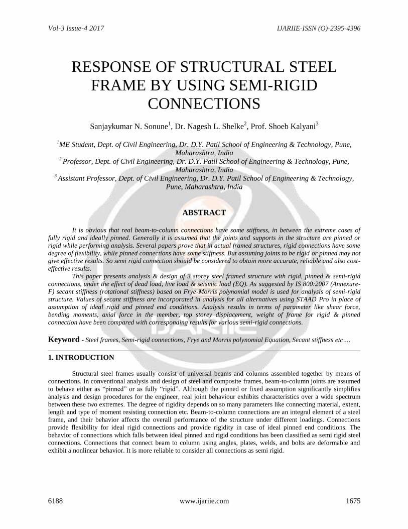
Vol-3 Issue-4 2017 IJARIIE-ISSN (O)-2395-4396 6188 www.ijariie.com 1675 RESPONSE OF STRUCTURAL STEEL FRAME BY USING SEMI-RIGID CONNECTIONS Sanjaykumar N. Sonune 1 , Dr. Nagesh L. Shelke 2 , Prof. Shoeb Kalyani 3 1 ME Student, Dept. of Civil Engineering, Dr. D.Y. Patil School of Engineering & Technology, Pune, Maharashtra, India 2 Professor, Dept. of Civil Engineering, Dr. D.Y. Patil School of Engineering & Technology, Pune, Maharashtra, India 3 Assistant Professor, Dept. of Civil Engineering, Dr. D.Y. Patil School of Engineering & Technology, Pune, Maharashtra, India ABSTRACT It is obvious that real beam-to-column connections have some stiffness, in between the extreme cases of fully rigid and ideally pinned. Generally it is assumed that the joints and supports in the structure are pinned or rigid while performing analysis. Several papers prove that in actual framed structures, rigid connections have some degree of flexibility, while pinned connections have some stiffness. But assuming joints to be rigid or pinned may not give effective results. So semi rigid connection should be considered to obtain more accurate, reliable and also cost- effective results. This paper presents analysis & design of 3 storey steel framed structure with rigid, pinned & semi-rigid connections, under the effect of dead load, live load & seismic load (EQ). As suggested by IS 800:2007 (Annexure- F) secant stiffness (rotational stiffness) based on Frye-Morris polynomial model is used for analysis of semi-rigid structure. Values of secant stiffness are incorporated in analysis for all alternatives using STAAD Pro in place of assumption of ideal rigid and pinned end conditions. Analysis results in terms of parameter like shear force, bending moments, axial force in the member, top storey displacement, weight of frame for rigid & pinned connection have been compared with corresponding results for various semi-rigid connections. Keyword - Steel frames, Semi-rigid connections, Frye and Morris polynomial Equation, Secant stiffness etc…. 1. INTRODUCTION Structural steel frames usually consist of universal beams and columns assembled together by means of connections. In conventional analysis and design of steel and composite frames, beam-to-column joints are assumed to behave either as “pinned” or as fully “rigid”. Although the pinned or fixed assumption significantly simplifies analysis and design procedures for the engineer, real joint behaviour exhibits characteristics over a wide spectrum between these two extremes. The degree of rigidity depends on so many parameters like connecting material, extent, length and type of moment resisting connection etc. Beam-to-column connections are an integral element of a steel frame, and their behavior affects the overall performance of the structure under different loadings. Connections provide flexibility for ideal rigid connections and provide rigidity in case of ideal pinned end conditions. The behavior of connections which falls between ideal pinned and rigid conditions has been classified as semi rigid steel connections. Connections that connect beam to column using angles, plates, welds, and bolts are deformable and exhibit a nonlinear behavior. It is more reliable to consider all connections as semi rigid.
Transcript of RESPONSE OF STRUCTURAL STEEL FRAME BY...
Vol-3 Issue-4 2017 IJARIIE-ISSN (O)-2395-4396
6188 www.ijariie.com 1675
RESPONSE OF STRUCTURAL STEEL
FRAME BY USING SEMI-RIGID
CONNECTIONS
Sanjaykumar N. Sonune1, Dr. Nagesh L. Shelke
2, Prof. Shoeb Kalyani
3
1ME Student, Dept. of Civil Engineering, Dr. D.Y. Patil School of Engineering & Technology, Pune,
Maharashtra, India 2 Professor, Dept. of Civil Engineering, Dr. D.Y. Patil School of Engineering & Technology, Pune,
Maharashtra, India 3 Assistant Professor, Dept. of Civil Engineering, Dr. D.Y. Patil School of Engineering & Technology,
Pune, Maharashtra, India
ABSTRACT
It is obvious that real beam-to-column connections have some stiffness, in between the extreme cases of
fully rigid and ideally pinned. Generally it is assumed that the joints and supports in the structure are pinned or
rigid while performing analysis. Several papers prove that in actual framed structures, rigid connections have some
degree of flexibility, while pinned connections have some stiffness. But assuming joints to be rigid or pinned may not
give effective results. So semi rigid connection should be considered to obtain more accurate, reliable and also cost-
effective results.
This paper presents analysis & design of 3 storey steel framed structure with rigid, pinned & semi-rigid
connections, under the effect of dead load, live load & seismic load (EQ). As suggested by IS 800:2007 (Annexure-
F) secant stiffness (rotational stiffness) based on Frye-Morris polynomial model is used for analysis of semi-rigid
structure. Values of secant stiffness are incorporated in analysis for all alternatives using STAAD Pro in place of
assumption of ideal rigid and pinned end conditions. Analysis results in terms of parameter like shear force,
bending moments, axial force in the member, top storey displacement, weight of frame for rigid & pinned
connection have been compared with corresponding results for various semi-rigid connections.
Keyword - Steel frames, Semi-rigid connections, Frye and Morris polynomial Equation, Secant stiffness etc….
1. INTRODUCTION
Structural steel frames usually consist of universal beams and columns assembled together by means of
connections. In conventional analysis and design of steel and composite frames, beam-to-column joints are assumed
to behave either as “pinned” or as fully “rigid”. Although the pinned or fixed assumption significantly simplifies
analysis and design procedures for the engineer, real joint behaviour exhibits characteristics over a wide spectrum
between these two extremes. The degree of rigidity depends on so many parameters like connecting material, extent,
length and type of moment resisting connection etc. Beam-to-column connections are an integral element of a steel
frame, and their behavior affects the overall performance of the structure under different loadings. Connections
provide flexibility for ideal rigid connections and provide rigidity in case of ideal pinned end conditions. The
behavior of connections which falls between ideal pinned and rigid conditions has been classified as semi rigid steel
connections. Connections that connect beam to column using angles, plates, welds, and bolts are deformable and
exhibit a nonlinear behavior. It is more reliable to consider all connections as semi rigid.

Vol-3 Issue-4 2017 IJARIIE-ISSN (O)-2395-4396
6188 www.ijariie.com 1676
2. SCOPE & OBJECTIVES OF STUDY
2.1 Objectives of Study
It is proposed to carryout analysis of multi-storey multi bay steel structure considering ideally rigid, ideally
pinned & semi-rigid beam end conditions in STAAD Pro using IS 800:2007. The following are the objectives of the
proposed work.
1) To Study the parameters like shear force, bending moments for beam with rigid, pinned & semi-rigid
connections.
2) To Study the parameters like shear force, axial force for column with rigid, pinned & semi-rigid
connections.
3) To study top storey displacement, weight of structure, base shear with rigid, pinned & semi-rigid
connections.
2.2 Scope
1) The analysis and design of steel structure with ideally rigid & ideally pinned beam end condition under
seismic loading.
2) The analysis and design of steel structure with semi-rigid beam end condition under seismic loading.
3) To compare response of rigid, pinned & semi-rigid frame structure subjected to seismic loads.
4) To study the parameters such as base shear, lateral displacement are compared along with the parameter
obtained from seismic analysis.
5) Comparing the analysis results for rigid, pinned & semi-rigid end conditions in terms of parameters like
shear force, bending moments, axial force in the member, top storey displacement, weight of frame, base
shear etc.
3. LITRATURE SURVEY
V. D. Kapgate, Dr. K. N. Kadam (2015) [1] This paper presents analysis of a pinned, rigid, semi rigid jointed
portal frame using a versatile program developed in FORTRAN language using stiffness matrix formulation, where
analysis has been done without changing source program and only with a minimal change in data file. This paper
describe in detail computer implementation of formulation of the program organization in the form of a flow chart.
Numerical is presented to show the effect of joint flexibility on overall response of structures. Single story portal
frame with semi rigid beam to column is analyzed by changing rotational spring stiffness. Results are presented to
show variation of bending moment, shear force and axial force.
M.E. Kartal et. al. (2010) [2] In this study, rotational spring stiffness-connection ratio relation is clearly explained
and revealed. A finite element program SEMIFEM is developed in FORTRAN language for the numerical analysis.
This program provides to define semi-rigid connections in terms of rotational spring stiffness or connection ratio
simultaneously. In the numerical applications, rotational spring stiffness-connection percentage relation of the semi-
rigid connected structural members is submitted. Semi-rigid connections are considered in column-to-foundation
connection of a portal frame, beam-to-column connection of a prefabricated structure, steel brace connection to
reinforced concrete (RC) frame of a steel X-braced RC frame and truss member connection to joint of a steel truss
system. The variation of moment, shear force, axial force, displacement and stress is investigated in a selected axis
of the structures. Consequently, semi-rigid connections should be considered in structural analyses to obtain the
most optimum results.
T. Otsuka1 et. al. (2008) [3] In this study, in order to obtain a rational design parameter involving the connection
factor that can be used in Japan, a fundamental study about the characteristic of multi-storied steel frames with
changes in the strength of the beam-to-column connections was performed via a static analysis. In order to formulate
a design condition involving the connections, four parameters were defined. The main parameter is the connection
factor, adopted when the small one changed to a large one, and a push-over static analysis with an earthquake load
was conducted. From the analysis results, information about the availability of the use of semi-rigid frames in Japan
was obtained.

Vol-3 Issue-4 2017 IJARIIE-ISSN (O)-2395-4396
6188 www.ijariie.com 1677
A Csébfalvi, G. Csébfalvi (2005) [4] In this study, a simplified beam-to-column connection is presented which was
specified in EC3 Annex J. The main aim of this paper was to investigate the effects of the rotational stiffness of
beam-to-column connections in the optimal design problem while the structural response is changing. In order to
capture the changes in the nodal force and moment distribution in terms of joint flexibility, the ANSYS finite
element analysis is applied. The structural model is formulated as a combination of 3D quadratic beam elements and
linear torsional springs. Present work deals with the effects of joint flexibility to the optimal design problem. The
design variables - including joint properties - are discrete. Results are presented for sway frames under different load
conditions. Also the relationship in between the end-fixity factor and the resulted optimal design is presented.
J.M.Cabrero, E.Bayo (2005) [5] The proposed method allows to optimize not only the size of the structural
profiles, but also the joint design to make it fit to the optimal theoretical values. Pre-design methods for semi-rigid
extended end-plate joints were also provided to easily check the feasibility and suitability of a connection design.
Two design examples were proposed to demonstrate the application of the proposed semi-rigid design methods, and
their results compared to pinned and rigid alternatives. The semi-rigid approach results in more economical
solutions. It must be pointed out that, in spite of optimizing the structural profiles, if the joints were not optimized,
the resulting structure cannot be considered optimal and even adequate, as its main differential characteristic, the
semi-rigid joint, has not been yet fully exploited. A design method suitable for semi-rigid joints was proposed. Apart
from minimizing the need for iteration, the main advantage is its similarity to the design method used at present for
the traditional types of joints (pinned and rigid).
4. METHODOLOGY
An analysis and design method has been employed for steel frames with semi-rigid connections using limit
state design provisions. Analysis takes into account the nonlinear behavior of beam-to-column connections. The
analysis and design of members has been done considering ideally rigid and ideally pinned end conditions using
STAAD Pro. for three storey framed structure. As suggested by IS 800:2007 (Annexure-F) secant stiffness
(rotational stiffness) based on Frye-Morris polynomial model is used for analysis of semi-rigid structure. The values
of secant stiffness are incorporated in analysis for all alternatives using STAAD Pro in place of assumption of ideal
rigid and pinned end conditions. Analysis results in terms of parameter like shear force, bending moments, axial
force in the member, top storey displacement, weight of frame for rigid & pinned connection have been compared
with corresponding results for various semi-rigid connections.
Design of members has been conducted using the codal provisions. The design process has been repeated
for selecting member cross-sections and connection parameters.
The methodology includes:
1) The selection of framed structure for study.
2) Working out loading details as per IS 875:1987 (Part I & II) & seismic parameters in accordance with Code
IS1893:2002 (Part-I).
3) Analysis & design of considered framed structure for ideally rigid and ideally pinned end conditions using
STAAD Pro. software.
4) Analysis & design of considered framed structure for semi-rigid end conditions by using the values of secant
stiffness incorporated at end conditions for all alternatives using STAAD Pro software.
5) Comparing the analysis results for rigid, pinned & semi-rigid end conditions in terms of parameter like shear
force, bending moments, axial force in the member, top storey displacement, weight of frame.
5. PROBLEM STATEMENT
A four bay three storey steel structure building is selected for analysis. The structure is analyzed for various load
combinations.
1. Geometrical Details of Structure:
X direction bay spacing = 5.0 m c/c
Z direction bay spacing = 4.0 m c/c
Floor height = 3.0 m c/c
Vol-3 Issue-4 2017 IJARIIE-ISSN (O)-2395-4396
6188 www.ijariie.com 1678
2. SBC for Soil at 3 m = 300 kN/m2
3. Wind Speed in the Area = 39 m/s
4. Seismic Zone = III
5. Material Properties for Structural Steel :
Unit mass of steel = 7850 kg/Cu.m
Modulus of Elasticity (E) = 2.10x10⁵ MPa
Poissons ratio = 0.3
Yield Stress (fy) = 250 Mpa
Tensile or Ultimate Stress (fu) = 410 MPa
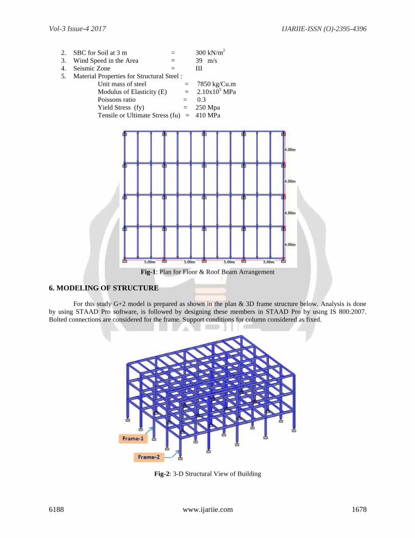
Fig-1: Plan for Floor & Roof Beam Arrangement
6. MODELING OF STRUCTURE
For this study G+2 model is prepared as shown in the plan & 3D frame structure below. Analysis is done
by using STAAD Pro software, is followed by designing these members in STAAD Pro by using IS 800:2007.
Bolted connections are considered for the frame. Support conditions for column considered as fixed.
Fig-2: 3-D Structural View of Building

Vol-3 Issue-4 2017 IJARIIE-ISSN (O)-2395-4396
6188 www.ijariie.com 1679
Initially two models were done for analysis and design:
1) With rigid end condition
2) With pinned end condition (i.e. moment release at beam ends)
Followed by four different models for semi-rigid framed structure have been done. To study the behavior of semi
rigid connections the values of secant stiffness used for beam end conditions as per suggested in IS 800:2007
(Annexure-F) depending upon the connection type.
3) Single Web Angle Connections (SWCA)
4) Double Web Angle Connections (DWCA)
5) Top and Seat without Web Angel Connections (TSWA)
6) Header Plate Connections (HPC)
Fig-3: Single web angle connection. Fig-4: Double Web Angle Connection.
Fig-5: Top and Seat Angle Connection. Fig-6: Header Plate Connection
Analysis is done for all the six models mentioned above to evaluated its structural performance with respect
to member strength, ductility and storey displacement. Also to get stability against the earthquake loads, the bracings
at end frames is provided. Otherwise for pinned connection, all columns will behave as cantilever and the frame is
unstable.
7. DETAILS OF LOADING
1) Dead Load (DL): The dead loads are calculated on basis of unit weights of materials given in IS 875 (Part
I): 1987. It includes the self-weight of beams, columns. The floor slab loads & wall loads have been
calculated and assigned as uniformly distributed loads on the beams. Assuming 125 mm thick RCC metal
deck slab & 200 mm thick brick wall.
Self-weight of Structure = From STAAD Model
Dead Load of Floor Slab = 3.125 kN/sq.m
Dead Load of Floor finishes = 1.0 kN/sq.m
Dead Load of Brick wall = 10.0 kN/m
2) Live Load/Imposed Load (LL): Live load are assumed in accordance with IS 875 (Part II):1987, as
follows
For floor live load consider as = 5.0 kN/sq.m
For roof live load consider as = 1.5 kN/sq.m

Vol-3 Issue-4 2017 IJARIIE-ISSN (O)-2395-4396
6188 www.ijariie.com 1680
3) Seismic Load (EL): The following values are used for seismic response in accordance with IS 1893:2002
(Part I), as
Seismic Zone = III
Seismic Zone factor (Z) = 0.16
Importance factor of structure (I) = 1
Response reduction factor (R) = 3
Type of Soil Site = II
4) Load Combinations:
Table -1: Primary Load Case
DL Dead Load
LL Live Load
ELX Earthquake in X direction
ELZ Earthquake in Z direction
Table -2: Load Combination for Strength Table -3: Load Combination for Serviceability
Sr.No. For Strength Criteria
Sr.No. For Serviceability Criteria
1 1.5DL + 1.5LL
1 1.0DL + 1.0LL
2 1.2DL + 1.2LL + 1.2ELX
2 1.0DL + 1.0LL + 1.0ELX
3 1.2DL + 1.2LL - 1.2ELX
3 1.0DL + 1.0LL - 1.0ELX
4 1.2DL + 1.2LL + 1.2ELZ
4 1.0DL + 1.0LL + 1.0ELZ
5 1.2DL + 1.2LL - 1.2ELZ
5 1.0DL + 1.0LL - 1.0ELZ
6 1.5DL + 1.5ELX
6 1.0DL + 1.0ELX
7 1.5DL - 1.5ELX
7 1.0DL - 1.0ELX
8 1.5DL + 1.5ELZ
8 1.0DL + 1.0ELZ
9 1.5DL - 1.5ELZ
9 1.0DL - 1.0ELZ
10 0.9DL + 1.5ELX
10 1.0DL
11 0.9DL - 1.5ELX
12 0.9DL + 1.5ELZ
13 0.9DL - 1.5ELZ

Vol-3 Issue-4 2017 IJARIIE-ISSN (O)-2395-4396
6188 www.ijariie.com 1681
8. COMPARISION OF ANALYSIS RESULTS FOR RIGID, PINNED & SEMI-RIGID
CONNECTIONS
The comparison has been made between ideal pinned and rigid end conditions for steel frame with different
semi rigid steel connections for assessment of different parameters like end span bending moment, mid span bending
moment, shear force, axial forces in member, weight of columns, weight of beams, total weight of frame, top storey
displacements. Variation of above parameters has been availed from analysis results using STAAD Pro.2006. For
presentation of results middle bay Frame-1 have been considered as shown in figure-8.
Fig-7: Elevation for Frame-1
Table -4: Types of Semi-rigid Connections
SWCA
Single Web Angle Connections
HPC
Header Plate Connections
TSWA
Top and Seat without Web Angel Connections
DWCA
Double Web Angle Connections
Table -5: Beam End Span Bending Moment (1.5DL+1.5EL)
Table -6: Beam Span Bending Moment (1.5DL+1.5LL)
Pinned SWCA HPC TSWA DWCA Rigid
B1, B4 0 10.5 20.1 22.4 32.7 137.0
B2, B3 0 10.5 20.2 22.5 32.8 131.0
B5, B8 0 10.5 20.5 22.5 32.4 133.0
B6, B7 0 10.5 20.5 22.5 32.6 128.0
B9, B12 0 9.5 17.8 19.2 26.6 80.7
B10, B11 0 9.5 17.9 19.3 26.6 76.3
End Span Bending Moment (KNm)Member
Pinned SWCA HPC TSWA DWCA Rigid
B1, B4 167.5 157.2 148.6 145.8 136.3 60.2
B2, B3 167.5 157.0 148.5 145.6 135.7 55.2
B5, B8 167.5 157.2 148.6 145.8 136.2 59.2
B6, B7 167.5 157.0 148.5 145.6 135.7 55.7
B9, B12 109.0 99.0 91.9 89.7 82.5 39.9
B10, B11 109.0 98.9 91.5 89.1 81.4 36.2
MemberBeam Span Bending Moment (KNm)

Vol-3 Issue-4 2017 IJARIIE-ISSN (O)-2395-4396
6188 www.ijariie.com 1682
Table -7: Beam Shear Force (1.5DL+1.5EL)
Table -8: Column Axial Force (1.5DL+1.5EL)
Table -9: Column Shear Force (1.5DL+1.5EL)
Table -10: Top Storey Displacement for Structure
Table -11: Total Weight of Structure
Pinned SWCA HPC TSWA DWCA Rigid
B1, B4 80.8 81.7 82.8 82.9 83.9 102.0
B2, B3 80.8 81.7 82.8 82.8 83.8 97.5
B5, B8 80.8 81.7 82.9 82.8 83.7 99.8
B6, B7 80.8 81.7 82.9 82.8 83.7 96.5
B9, B12 52.8 53.2 54.3 54.1 54.7 63.1
B10, B11 52.8 53.2 54.2 54.0 54.5 59.4
MemberBeam Shear Force (KN)
Pinned SWCA HPC TSWA DWCA Rigid
1C1,1C5 456 459 462 462 464 491
1C2,1C4 654 654 654 654 654 665
1C3 653 653 653 653 653 653
2C1,2C5 282 284 286 286 287 301
2C2,2C4 408 408 408 408 408 414
2C3 407 407 407 407 407 407
3C1,3C5 108 108 109 109 109 112
3C2,3C4 162 162 162 162 162 164
3C3 161 161 161 161 161 161
MemberColumn Axial Force (KN)
Pinned SWCA HPC TSWA DWCA Rigid
1C1,1C5 13.1 15.8 18.8 19.4 20.8 44.4
1C2,1C4 13.1 15.3 17.7 18.7 19.3 44.0
1C3 13.1 15.4 17.8 18.7 19.3 43.1
2C1,2C5 9.1 13.0 16.1 16.5 18.3 42.6
2C2,2C4 9.5 11.9 14.6 15.5 16.3 43.0
2C3 9.3 11.6 15.2 15.5 15.9 41.8
3C1,3C5 5.6 7.2 7.9 9.5 11.4 37.2
3C2,3C4 5.2 7.0 8.2 9.0 10.5 29.5
3C3 5.1 6.8 8.1 9.2 10.3 26.2
MemberColumn Shear Force (KN)
Pinned SWCA HPC TSWA DWCA Rigid
Z-Dir 35.55 34.20 33.81 31.06 30.31 17.44
X-Dir 20.50 17.50 15.65 13.03 12.36 11.72
DirectionTop Storey Displacement for Structure (mm)
Pinned SWCA HPC TSWA DWCA Rigid
725 710 710 705 705 671
Total weight of Structure (KN)

Vol-3 Issue-4 2017 IJARIIE-ISSN (O)-2395-4396
6188 www.ijariie.com 1683
Table -12: Base Shear
Direction Base Shear (KN)
Pinned SWCA HPC TSWA DWCA Rigid
X & Z Dir 598.43 598.24 598.07 597.87 597.87 595.44
Above analysis results can be graphically represented as below:
Fig-8: End Span Bending Moment for 1.5DL+1.5LL
It has been observed that increase in end span moments in the beam enhances with increase in rigidity of end
conditions for the beam as presented in Figure 8.
Fig-9: Beam Span Bending Moment for 1.5DL+1.5LL
Mid span moments in beam reduce with increase in rigidity of end conditions of the beam for vertical load cases as
shown in Figure 9.
0
20
40
60
80
100
120
140
160
Pinned SWCA HPC TSWA DWCA Rigid
Bea
m E
nd
Mo
men
ts (
kN
)
Connection Type
B1, B4
B5, B8
B9, B12
0
20
40
60
80
100
120
140
160
180
Pinned SWCA HPC TSWA DWCA Rigid
Bea
m S
pa
n B
.M. (
kN
-m )
Connection Type
B1, B4
B5, B8
B9, B12

Vol-3 Issue-4 2017 IJARIIE-ISSN (O)-2395-4396
6188 www.ijariie.com 1684
Fig-10: Beam Shear Force for 1.5DL+1.5EL
Enhancement has been observed in shear force with increase in rigidity for beams horizontal load cases as shown in
Figure 10.
Fig-11: Column Axial Force for 1.5DL+1.5EL
It has been observed from comparison of axial force in column that it slightly increases with increase in rigidity of
end conditions for horizontal load cases as given in Figure 11.
Fig-12: Column Shear Force for 1.5DL+1.5EL
Shear force in columns increase with increase in rigidity of end conditions for horizontal load cases as narrated in
Figure 12.
0
20
40
60
80
100
120
Pinned SWCA HPC TSWA DWCA Rigid
Bea
m S
hea
r F
orc
e (k
N)
Connection Type
B1, B4
B5, B8
B9, B12
0
100
200
300
400
500
600
Pinned SWCA HPC TSWA DWCA Rigid
Co
lum
n A
xia
l F
orc
e (k
N)
Connection Type
1C1,1C5
2C1,2C5
3C2,3C4
0
10
20
30
40
50
Pinned SWCA HPC TSWA DWCA Rigid
Co
lum
n S
hea
r F
orc
e (k
N)
Connection Type
1C1,1C5
2C1,2C5
3C1,3C5

Vol-3 Issue-4 2017 IJARIIE-ISSN (O)-2395-4396
6188 www.ijariie.com 1685
Fig-13: Total Weight of Structure
Weight of structure decreases with increase in rigidity of the frame as presented in Figure 13.
Fig-14: Top Storey Displacement of Structure
Increment in top storey displacements is observed with increase in flexibility of semi-rigid connections as presented
in Figures 14.
Figure 15. Base Shear for Structure
Increment is observed in base shear with increase in flexibility of semi-rigid connections as presented in Figure 15.
640
660
680
700
720
740
Pinned SWCA HPC TSWA DWCA Rigid
To
tal
Weig
ht
of
Str
uct
ure
(KN
)
Connection Type
0.00
5.00
10.00
15.00
20.00
25.00
30.00
35.00
40.00
Pinned SWCA HPC TSWA DWCA Rigid
To
p S
tore
y D
isp
lace
men
t (m
m)
Connection Type
Z-Dir
X-Dir
593
594
595
596
597
598
599
Pinned SWCA HPC TSWA DWCA Rigid
Ba
se S
hea
r (k
N)
Connection Type

Vol-3 Issue-4 2017 IJARIIE-ISSN (O)-2395-4396
6188 www.ijariie.com 1686
9. CONCLUSIONS
Based on the Analysis results, the following conclusion can be made:
In general it is observed that bending moments in floor beams are reduced at the ends and increased at mid
span due to change over from rigid to semi-rigid beam and column connection. The variation in BM depends on the
semi rigidity of connection. It means that BM at ends reduced from fixed, Double Web Connection Angle (DWCA),
Top and Seat without Web Angel Connections (TSWA), Header Plate Connections (HPC) to Single Web
Connection Angle (SWCA) connection. Also increase in BM at mid span is observed from DWCA, TSWA, HPC,
SWCA to pinned connection. This observation is quite obvious structurally.
At fixed base axial force is not appreciably affected due to type of connection but shear force in the column
is reduced substantially. Therefore, in semi rigid steel frames, the columns do not derive any benefit of beam
framing because of poor horizontal support. The column resists major horizontal action.
The storey displacement is increases in semi rigid connection and it is larger in case of Header Plate
Connection, Single Web Connection Angle & pinned connections. Need to provide suitable bracing system to
control the deflection.
The analysis response of the frames has indicated that a reduction in the joint moment is accompanied by
an increase in the span moments. Reducing joint moments is advantageous as detailing, modeling and design of
joints is the most cumbersome part of steel frame design. In RCC-steel structural construction beams are usually
laterally restrained and have sufficient strength to sustain design loads in their span than connection region. This will
make semi rigid connections an economical design solution.
Also, it is observed that base shear reduces with increase in rigidity. Hence, it is recommended to use semi
rigid connection for realistic behaviour check of Steel structural frames.
All these connections are idealized for analysis and presently many researcher are of the opinion that the
actual stiffness shall be used for analysis instead of restricting to rigid or pinned depend upon the type of connection
provided.
10. ACKNOWLEDGEMENT
I express my deepest gratitude to my project guide Prof. Dr. Nagesh Shelke & Co-guide
Prof. Shoeb Kalyani, whose encouragement, guidance and support me to develop an understanding of the subject.
I would like to thank Principal, Dr. Ashok S. Kasnale and Dr. Sanjay K. Kulkarni H.O.D of Civil
Department, Dr. D.Y.Patil School of Engineering & Technology for providing their invaluable advice. This would
help me to work and completing this project.
11. REFERENCES
[1]. Dr. K. N. Kadam, V. D. Kapgate,”Response of Semi Rigid Connections on Frame Behaviour,” International
Journal on Recent and Innovation Trends in Computing and Communication, Volume: 3 Issue: 2, February
2015.
[2]. M.E. Kartal, H.B. Basaga, A. Bayraktar and M. Muvafık, “Effects of Semi-Rigid Connection on Structural
Responses,” Electronic Journal of Structural Engineering (10) 2010.
[3]. T. Otsuka1, W.N. Sui1 and M.Yamanari2, “Design Parameter of Semi-Rigid Connections Through Static Steel
Frame Analysis”, The 14th World Conference on Earthquake Engineering October 12-17, 2008, Beijing, China.
[4]. A Csébfalvi1 , G. Csébfalvi2, “Effect of Semi-Rigid Connection in Optimal Design of Frame Structures”, 6th
World Congresses of Structural and Multidisciplinary Optimization Rio de Janeiro, 30 May-03 June 2005,
Brazil.
[5]. J.M.Cabrero, E.Bayo, “Development of practical design methods for steel structures with semi-rigid
connections”, Engineering Structures 27 (2005) 1125-1137 [34].
[6]. Subramanian, N. (2008). “Design of Steel Structures”, Oxford, University Press, India, 267-551.
[7]. IS 800:2007, Code of Practice for General Construction in Steel, Bureau of Indian Standard, New Delhi.
[8]. IS1893:2002 (Part I) Criteria for earthquake resistant design of structure
[9]. IS: 875:1987 (Part I) Code of practice for design loads (other than earthquake) for buildings and structures-
(Dead Load)
[10]. IS: 875:1987 (Part II) Code of practice for design loads (other than earthquake) for buildings and structures-
(Imposed Load)