Resistance and Propulsion of Shipsbveitch/courses/r-p/Assignments/blade-element.pdf · Resistance...
5
1 Introduction to R & P Resistance and Propulsion of Ships Blade element theory Introduction to R & P Blade sections - elements Resistance and Propulsion of Ships In blade element theory, the prop is treated in more detail than in momentum theory (where it was treated as an actuator disk of area A o ). In blade element theory, we consider the blade to be made up of a series of annular elements of width dr . R Blade element at r of width dr r dr Introduction to R & P Blade elements Resistance and Propulsion of Ships Recall geometry – we can look at each of the blade elements in turn and consider the fluid velocity over each. Pitch 2πr Suction side pressure side Pitch datum line φ Introduction to R & P Blade elements Resistance and Propulsion of Ships Simple section velocity – the section is advancing at V A and has a tangential velocity of 2πnr . 2πnr Pitch datum line φ V A Resultant velocity Introduction to R & P Blade elements Resistance and Propulsion of Ships Fluid velocity relative to the blade element. 2πnr Pitch datum line φ V A Resultant velocity β α G geometric incidence angle (angle of attack) β advance angle α G Introduction to R & P Blade elements Resistance and Propulsion of Ships We can include the induced velocity components. These are the velocities induced by the propeller action. 2πnr Pitch datum line φ V A Resultant velocity α G β α E β i u A u T α E effective angle of attack, or effective incidence angle β i hydrodynamic pitch, or advance angle
Transcript of Resistance and Propulsion of Shipsbveitch/courses/r-p/Assignments/blade-element.pdf · Resistance...

1
Introduction to R & P
Resistance and Propulsion of Ships
Blade element theory
Introduction to R & P
! Blade sections - elements
Resistance and Propulsion of Ships
In blade element theory, the prop is treated in more detail than in momentum theory (where it was treated as an actuator disk of area Ao).
In blade element theory, we consider the blade to be made up of a series of annular elements of width dr .
R
Blade element at r of width dr
r
dr
Introduction to R & P
! Blade elements
Resistance and Propulsion of Ships
Recall geometry – we can look at each of the blade elements in turn and consider the fluid velocity over each.
Pitch
2πr Suctio
n side
pressure s
ide
Pitch datu
m line
φ
Introduction to R & P
! Blade elements
Resistance and Propulsion of Ships
Simple section velocity – the section is advancing at VA and has a tangential velocity of 2πnr.
2πnr
Pitch datu
m line
φ VA
Resultant velocity
Introduction to R & P
! Blade elements
Resistance and Propulsion of Ships
Fluid velocity relative to the blade element.
2πnr
Pitch datu
m line
φ VA
Resultant velocity
β
α G geometric incidence angle (angle of attack)
β advance angle
αG
Introduction to R & P
! Blade elements
Resistance and Propulsion of Ships
We can include the induced velocity components. These are the velocities induced by the propeller action.
2πnr
Pitch datu
m line
φ VA
Resultant velocity
αG
β
αE
βi
uA
uT
α E effective angle of attack, or effective incidence angle
βi hydrodynamic pitch, or advance angle

2
Introduction to R & P
! Blade elements
Resistance and Propulsion of Ships
The induced velocity component uT (tangential component) will have opposite sense to 2πnr . The induced velocity component uA (axial component) will have same sense as VA .
2πnr
Pitch datu
m line
φ VA
αG
β
αE
βi
uA
uT
α E effective angle of attack, or effective incidence angle
βi hydrodynamic pitch, or advance angle
uA
uT
Introduction to R & P
! Blade elements
Resistance and Propulsion of Ships
Once we know the velocities at each section, and the lift and drag characteristics of the sections, then we can evaluate the elemental forces.
2πnr - uT
Pitch datu
m line
VA + uA
Resultant velocity
αE
βi
Introduction to R & P
! Blade elements
Resistance and Propulsion of Ships
2πnr - uT
Pitch datu
m line
VA + uA
Resultant velocity
αE
Hydrodynamic LIFT acts perpendicular to the resultant velocity.
Hydrodynamic DRAG acts parallel to the resultant velocity.
Elemental Lift dL
Elemental Drag dD
Elemental resultant force
Introduction to R & P
! Blade elements
Resistance and Propulsion of Ships
2πnr - uT
Pitch datu
m line
VA + uA
Resultant velocity
αE
Elemental Lift dL
Elemental Drag dD
Elemental resultant force
Elemental Thrust dT
Elemental Torque dF x r
Introduction to R & P
! Equations
Resistance and Propulsion of Ships
Introduction to R & P
! Lift and drag characteristics
Resistance and Propulsion of Ships
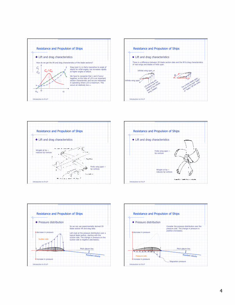
How do we get the lift and drag characteristics of the blade sections?

3
Introduction to R & P
! Lift and drag characteristics
Resistance and Propulsion of Ships
How do we get the lift and drag characteristics of the blade sections?
If we use “standard” sections, then we can use existing lift and drag coefficients that have been determined from tests (typically in a wind tunnel).
Lift & drag coefficients are determined for uniform flow conditions using 2-D blade sections (rather than sections having some thin width dr).
In practice, this typically means that a wing of some span and constant cross section is tested. The span will typically correspond to the width of the (wind tunnel’s) test section.
A good source of data for foil section lift & drag data is the NACA sections evaluated by Abbott & von Doernhoff (Theory of Wing Sections).
Introduction to R & P
! Lift and drag characteristics
Resistance and Propulsion of Ships
How do we get the lift and drag characteristics of the blade sections?
We can do experiments in a wind or water tunnel, or even in a tow tank
Introduction to R & P
! Lift and drag characteristics
Resistance and Propulsion of Ships
How do we get the lift and drag characteristics of the blade sections?
Test section ~ instrumented part of facility.
This is where the “wing” would be positioned.
Introduction to R & P
! Lift and drag characteristics
Resistance and Propulsion of Ships
How do we get the lift and drag characteristics of the blade sections?
Lift and drag forces on the wing are measured in steady flow conditions at incrementally varied angles of attack. The results are non-dimensionalized and plotted.
Test section with “wing” of uniform section across the span
α
b
Introduction to R & P
! Lift and drag characteristics
Resistance and Propulsion of Ships
How do we get the lift and drag characteristics of the blade sections?
CL is an approximately linear function of α for small angles of attack.
CL goes to zero at an angle α<0. This is the zero lift angle, denoted α0 .
α
b CL
CD
CL
CD
α α0 0
Introduction to R & P
! Lift and drag characteristics
Resistance and Propulsion of Ships
Consider the effect of α0 on the the velocity diagram and lift and drag.
Note that non-zero zero lift angles are due to camber. (So a symmetric section would have α0 =0).
Pitch datu
m line
αE Resultant velocity Zer
o lift l
ine
α0
If we have an incidence velocity along the zero lift line, we will get no lift. We include the effect of zero lift angle in the hydrodynamic angle of attack in order to use the lift and drag data.
αi = αE - α0
4
Introduction to R & P
! Lift and drag characteristics
Resistance and Propulsion of Ships
How do we get the lift and drag characteristics of the blade sections?
Drag (and CD) is fairly insensitive to angle of attack for small angles, but increases rapidly at higher angles of attack.
We have to recognize that L and D occur together, so the ratio of L/D is an important section characteristic and we are interested in operating where L/D is maximum. This occurs at relatively low α.
CL CD
CL
CD
α α0 0
CL / CD
Introduction to R & P
! Lift and drag characteristics
Resistance and Propulsion of Ships
There is a difference between 2D blade section data and the lift & drag characteristics of real wings and blades of finite span.
b
Infinite wing span
Infinite wing span
Lift an
d drag are
consta
nt over t
he
span of the in
finite
wing (blad
e) For a f
inite blad
e span,
some o
f the lo
ad “spills”
or “lea
ks” off
the ends.
Introduction to R & P
! Lift and drag characteristics
Resistance and Propulsion of Ships
Finite wing span ~ tip vortices
Winglet at tip ~ reduces tip vortices
Introduction to R & P
! Lift and drag characteristics
Resistance and Propulsion of Ships
Finite wing span ~ tip vortices
Winglet at tip ~ reduces tip vortices
Introduction to R & P
! Pressure distribution
Resistance and Propulsion of Ships
So we can use experimentally derived 2D blade section lift and drag data.
Let’s look at the pressure distribution over a typical blade section, starting with the suction side. The change in pressure on the suction side is negative (decreases).
Pitch datum line
Resultant velocity
Suction side
increase in pressure
decrease in pressure
Introduction to R & P
! Pressure distribution
Resistance and Propulsion of Ships
Pitch datum line
Resultant velocity
decrease in pressure
increase in pressure
Pressure side
Consider the pressure distribution over the pressure side. The change in pressure is positive (increases).
Stagnation pressure
5
Introduction to R & P
! Pressure distribution
Resistance and Propulsion of Ships
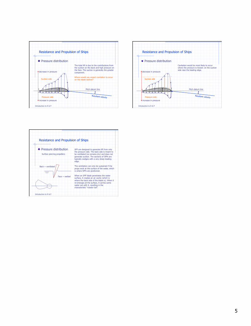
The total lift is due to the contributions from the suction on the back and high pressure on the face. The suction is generally the greater component.
Where would you expect cavitation to occur on this blade section?
Pitch datum line
Resultant velocity
Suction side
increase in pressure
decrease in pressure
Pressure side
Introduction to R & P
! Pressure distribution
Resistance and Propulsion of Ships
Cavitation would be most likely to occur where the pressure is lowest: on the suction side near the leading edge.
Pitch datum line
Resultant velocity
Suction side
increase in pressure
decrease in pressure
Pressure side
Introduction to R & P
! Pressure distribution
Resistance and Propulsion of Ships
SPP are designed to generate lift from only the pressure side. The back side is meant to be ventilated (so remains dry) and does not generate suction. The sections of SPPs are typically wedges with a very sharp leading edge.
The ventilation can only be sustained if the props work at the surface of the water, which is where SPPs are positioned.
When an SPP blade penetrates the water surface, it creates an air cavity (which is where the back side of the blade is). When it re-emerges at the surface, it carries some water out with it, resulting in the characteristic “rooster tail”.
Face ~ wetted
Back ~ ventilated
Surface piercing propellers