Residual Stresses Measurement and Causes in...
20
Key- Note- Papers Residual Stresses - Measurement and Causes in Machining Processes E. Brinksmeier, Hannover; J. T. Cammett, Cincinnati; W. Konig (l), Aachen; P. Leskovar (2). Ljubljana; J. Peters (l), Leuven; H. K. Tonshoff (l), Hannover Sumary The fmctional behaviour of a machined component is substantially determiped by the physical state of its surface includinq the residual stress distribution ?ear ttc surface. The necessity to come to nore exact methods of layout for machined components compels one to take "surface integrity" as defined by W. Field /1/ and herewith residual stresses into consideration. Residual stresses dircccly influence the defornation of workpieces, their static and dynamic strcnnth, and their chemical and electrical properties. According to the relevance of residual stresses generated by machining, several laboratories affi- liated with CIRP worked on a cooperative investigation of measurement techniques to define the state of the art. Measurements of residual stress distributions generated by some important machining pro- cesses have been made. This paper gives a report and tries to show how the possible sources for de- velopment of residual stresses are involved. 1. Detrimental and Favourable Influences of Residual Stresses Residual stresses in a workpiece are a function of its material processing and machining history. Residual stress can enhance or impair the functional behaviour of a machined part. Economic and technical aspects re- quire better utilization and higher loading of ma- chines and plants and their components. Thus methods of projection and desiqn have to be improved /l/. The physical state of high-duty workpieces has to be described precisely. This includes the knowledge of residual stresses in the component and especially in its surface layers. The machining processes which generate the functio- nally relevant surfaces of a component have great im- portance for the development of the physical state of the surface and the residual stress distribution in it. For many applications, the properties of a part's surface are dominant for the functional behaviour of the whole component. Pig. 1 gives a summary of the most important effects of residual stresses on mecha- nical and electrical components. This list is not Effects of residuol stresses static dynamic strength deto rmotion JI JL magnettzatlon resistance Fig. 1: Effects of residual stresses complete. There are other effects such as optical, acoustical or thermal results of residual stresses which cannot be discussed here. Some examples of the effects mentioned in figure 1 are described in follo- wing sections. 1.1 Deformations by Residual Stresses Residual stresses act in a body without external for- ces or moments. The internal forces form a system of equil.ibriun. If parts of the body are taken away, for instance by machining, the state of equilibrium is generally disturbed, and the body has to react by de- formations. This is an effect well-known to production engineers, which can be observed, for example, when machining a casting. If this casting is not heat treated for stress relief and if it is unsymmetri- cally machined, it deforms considerably after it is unclamped from the machine tool. This is the reason why the experienced worker releases the clamping for- ces of the workpiece after roughing and taking off large portions of the stressed material before fini- shing. The deformation of the part is roughly propor- tional to the removed cross-section of material. In the subsequent finishing only thin layers are removed so that the detrimental effects of the residual stresses from the casting process are minimized. This effect must not be mixed up with the input of re- sidual stresses by machining (fig. 2). As will later be explained in detail, the machining process gene- rates residual stresses by plastic deformation or me- talluryical transformations. These residual stresses have only limited depth of penetration on the order of some hundredth of millimeters. But especially for thin workpieces, this can also lead to relevant de- formations. By planinq of a 1 m long beam with a thickness of 20 mm, the deflection may be about 1 nun /2/. During the machining process or shortly after- wards, thermal influences can cause further deforma- tions. During machining the workpiece can be heated asymmetrically. By this temperature profile and the thermal expansion thermal stresses are generated and result in an additional deformation which, however, diminishes after temperature compensation (fig. 2). An important role is played by deformations caused by residual stresses in sheet metal forming /3,4,5,6/. Generally, plastic and elastic strains arise by ben- ding. The bending angle given by the form of the die Induc\\on 01 stresses by machining cross stress section dlstrlbutiOn deformed w o r k piece Fig. 2: Deformations of a workpiece by machining or the position of the tools is not identical with the angle at the workpiece after force release. Be- cause of the elastic strains the bent part springs back (fig. 3). The spring-back angle is especially large at locations of high elastic strains as com- pared with the plastically formed part of the sheet. A correction of the tools by this deviation is neces- sary /7.8/. Similar effects have to be considered where nonuniform - especially elastic-plastic defor- mations as in twisting - take place /9/. 1.2 Influence on Static Strength From a macroscopic point of view residual stresses act like a prestress state of the material. For ma- terials which are deformable and which have a charac- teristic yield point the residual stresses must in- fluence the level of the yield strength. Assuming a criterion of plastic flow, the elastic limit can be calculated if the stress distribution is given. This was experimentally proved by several authors /lO,ll/. Specimens of free cutting steel 9823 Pb were provided with different residual stress distributions by dra- wing and dressing. In fig. 4 the elastic limit is Annals of the CIRP Vol. 31/2/1982 49 1
Transcript of Residual Stresses Measurement and Causes in...
Key- Note- Papers
Residual Stresses - Measurement and Causes in Machining Processes
E. Brinksmeier, Hannover; J. T. Cammett, Cincinnati; W. Konig (l) , Aachen; P. Leskovar (2). Ljubljana; J. Peters ( l ) , Leuven; H. K. Tonshoff ( l ) , Hannover
Sumary The fmctional behaviour of a machined component is substantially determiped by the physical state of its surface includinq the residual stress distribution ?ear ttc surface. The necessity to come to nore exact methods of layout for machined components compels one to take "surface integrity" as defined by W . Field /1/ and herewith residual stresses into consideration. Residual stresses dircccly influence the defornation of workpieces, their static and dynamic strcnnth, and their chemical and electrical properties.
According to the relevance of residual stresses generated by machining, several laboratories affi- liated with CIRP worked on a cooperative investigation of measurement techniques to define the state of the art. Measurements of residual stress distributions generated by some important machining pro- cesses have been made. This paper gives a report and tries to show how the possible sources for de- velopment of residual stresses are involved.
1. Detrimental and Favourable Influences of Residual Stresses
Residual stresses in a workpiece are a function of its material processing and machining history. Residual stress can enhance or impair the functional behaviour of a machined part. Economic and technical aspects re- quire better utilization and higher loading of ma- chines and plants and their components. Thus methods of projection and desiqn have to be improved / l / . The physical state of high-duty workpieces has to be described precisely. This includes the knowledge of residual stresses in the component and especially in its surface layers.
The machining processes which generate the functio- nally relevant surfaces of a component have great im- portance for the development of the physical state of the surface and the residual stress distribution in it. For many applications, the properties of a part's surface are dominant for the functional behaviour of the whole component. Pig. 1 gives a summary of the most important effects of residual stresses on mecha- nical and electrical components. This list is not
E f f e c t s of residuol s t r e s s e s
s t a t i c d y n a m i c s t r e n g t h
d e t o r m o t i o n
J I JL m a g n e t t z a t l o n resistance
Fig. 1: Effects of residual stresses
complete. There are other effects such as optical, acoustical or thermal results of residual stresses which cannot be discussed here. Some examples of the effects mentioned in figure 1 are described in follo- wing sections.
1 . 1 Deformations by Residual Stresses
Residual stresses act in a body without external for- ces or moments. The internal forces form a system of equil.ibriun. If parts of the body are taken away, for instance by machining, the state of equilibrium is generally disturbed, and the body has to react by de- formations. This is an effect well-known to production engineers, which can be observed, for example, when machining a casting. If this casting is not heat treated for stress relief and if it is unsymmetri- cally machined, it deforms considerably after it is unclamped from the machine tool. This is the reason why the experienced worker releases the clamping for- ces of the workpiece after roughing and taking off large portions of the stressed material before fini- shing. The deformation of the part is roughly propor- tional to the removed cross-section of material. In the subsequent finishing only thin layers are removed so that the detrimental effects of the residual
stresses from the casting process are minimized.
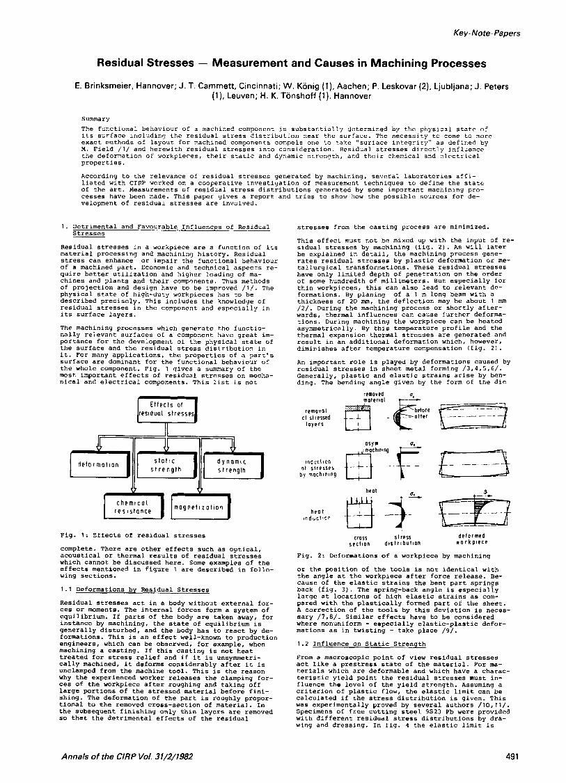
This effect must not be mixed up with the input of re- sidual stresses by machining (fig. 2 ) . As will later be explained in detail, the machining process gene- rates residual stresses by plastic deformation or me- talluryical transformations. These residual stresses have only limited depth of penetration on the order of some hundredth of millimeters. But especially for thin workpieces, this can also lead to relevant de- formations. By planinq of a 1 m long beam with a thickness of 2 0 mm, the deflection may be about 1 nun / 2 / . During the machining process or shortly after- wards, thermal influences can cause further deforma- tions. During machining the workpiece can be heated asymmetrically. By this temperature profile and the thermal expansion thermal stresses are generated and result in an additional deformation which, however, diminishes after temperature compensation (fig. 2 ) .
An important role is played by deformations caused by residual stresses in sheet metal forming / 3 , 4 , 5 , 6 / . Generally, plastic and elastic strains arise by ben- ding. The bending angle given by the form of the die
Induc\\on 01 s t r e s s e s
b y machin ing
cross s t ress s e c t i o n d l s t r l b u t i O n
d e f o r m e d w o r k p i e c e
Fig. 2: Deformations of a workpiece by machining
or the position of the tools is not identical with the angle at the workpiece after force release. Be- cause of the elastic strains the bent part springs back (fig. 3 ) . The spring-back angle is especially large at locations of high elastic strains as com- pared with the plastically formed part of the sheet. A correction of the tools by this deviation is neces- sary / 7 .8 / . Similar effects have to be considered where nonuniform - especially elastic-plastic defor- mations as in twisting - take place /9/. 1.2 Influence on Static Strength
From a macroscopic point of view residual stresses act like a prestress state of the material. For ma- terials which are deformable and which have a charac- teristic yield point the residual stresses must in- fluence the level of the yield strength. Assuming a criterion of plastic flow, the elastic limit can be calculated if the stress distribution is given. This was experimentally proved by several authors /lO,ll/. Specimens of free cutting steel 9823 Pb were provided with different residual stress distributions by dra- wing and dressing. In fig. 4 the elastic limit is
Annals of the CIRP Vol. 31/2/1982 49 1
' .G I - c o l c u l o t e d ( P r o k s a ) 0
0 I 0.032 0.10 0.3 2 1.0
r e 1 r u r v o t u r e s I r , Fig. 3: Spring back in sheet netal bending
shown to depend on the maximum residual stress compo- nent in the axial direction. It can be seen, that the elastic limit (Rp = 0,005) is decreased up to 40 % from the unstressed state. The beginning of plastic deformation during the tensile test is eased by resi- dual stresses considerably which follows from the prestressed-material-model. In pure tension or com- pression loading, the elastic limit must be lowered by the presence of uniaxial residual stresses indepen- dent of their distribution. In bending or multiaxial stress distributions even an increase of the elastic limit can be realized.
For buckling load the critical stress is always lowered by residual stresses. This can be shown by considering the elastic-plastic state of loaded bars / 1 2 / (fig. 5). Thiirlimann / 1 3 / gives an explanation using a three-bar model, of which the bars 1 are sub- jected by tension and the bar 2 is compressed by the rigid traverses. If the system is loaded by compres- sive forces, bar 2 reaches the yield point earlier and will then bear only less load per unit of strain (non linear state). Thurlimann has proved this effect by experiments.
d o = 2 L m m I 1
o: 100 2M1 300 LOO Nlmn'500 max. r e s i d u a l s t r e s s
Fig. 4: Elastic limit dependent of residual stresses
\ I . ', E u l e r ' s hyperbo loe without res stresses d
L.l L.l
L w i t h res . s t resses - L.l
OI
5 - = " = D
- rotio 01 slenderness s, It/,
Fig. 5: Decrease of buckling strength by residual stresses
Increasing the strength of a component by prestressing is extensivly used in technical applications. Dies for extrusion arc often built by two cylinders to be able to prestress the inner part and to bring it to a less critical state during operation. In high-pressure- physics this principle is still extended. Fig. 6 shows a "belt" apparatus which is used to synthesize dia- monds / l a / . The synthesis is accomplished at tempera- tures of nore than 1600 K at pressures of more than 55 kbar.
a
A c r o s s - s e c t i o n a l v i e w t h e s a m p i e c e l l
Fig. 6: Belt apparatus for diamond synthesizing
Whereas the apparatus shown consists of built dies where the residual stresses are reached by assembly, dies can also be prestressed by heat treatment /15/. Fig. 7 shows the residual stress distribution which was generated in a die made from cold forging steel 90 Cr 3 by cooling it from the bore. In the time-tem- perature-transformation diagram the temperature course for the inner and outer surface of the hollow cylinder is given. The residual stress distribution can be cal- culated from these data / l b / . It is characterized by high compressive stress in the axial and the tangen-
(Johnson)
t r e o t m e n t I I 1 EOC'C I bore wotcr
'0 loo 5 1000 t i m e
O X I O I t o naen t i 0 1
300'2. 260'C
LO m i n l o i r Zh!o'r
r e 1 a r e 0 A I A D
Fig. 7: Residual stresses in cold forging dies
tial directions. This distribution is very well suited to compensate stresses in the die by cold forging.
In disk springs a residual stress distribution is ge- nerated to prevent relaxation effects. These elements are suited to transmit high forces at low spring de-
(Juckel)
492
formations. They have the shape 0- a truncated cone and arc loaded along the axis of the cone. They are designed to be elastical?y deformed 3 / 4 o C thc geome- trically possible stroke. The actinq strcsscs therebj. cxceed the yield strength, which means that thc sprir.g tends to relax /17,16!’. This c a n be avoided by impo- sing a residual stress state ( f i g . 8 ) The Eigurc s?io.ds
l
a. l o n o e n t i o , stress ~. u n e h nomino i c o ~ d l t
Fig. 8: Stress distribution in a disk spring
the theoretical stresses by external force and the stress distribution which results from these and the residual stresses. The latter can be generated by overloading the disk springs in a special program. It has been experimentally proved by residual stress mea- surements / 1 9 / that, after this treatment, practically no relaxation or change of stress distribution takes place.
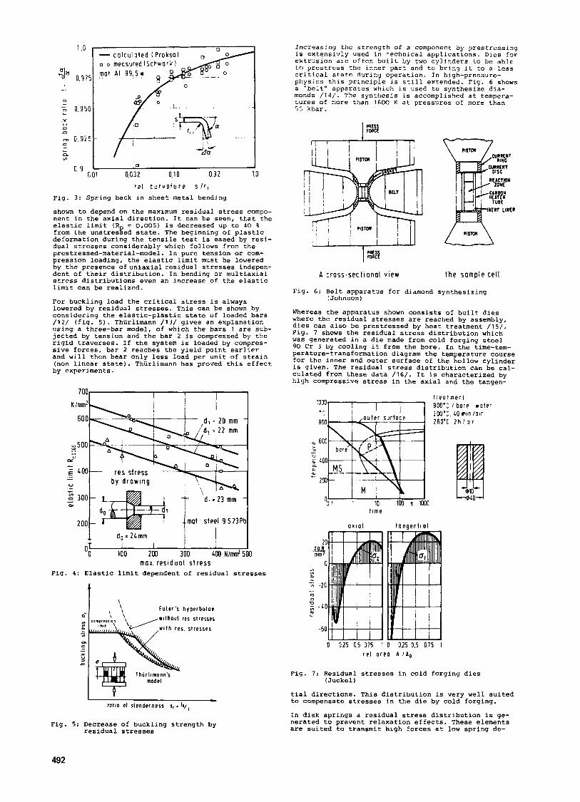
In the preceding examples the loaded components con- sisted of plastically deformable material. If the material is brittle, residual stresses may lead to cracks if the resulting stresses exceed the strenqth of the material at any point. Fig. 9 shows the spindle of a grinding machine which was nitrided and then ground. Using the magnetic flux test axisparallel cracks can be made visiable. A cross-sectioning and
Fig. 10: Grinding cracks in a crankshaft !Pohl)
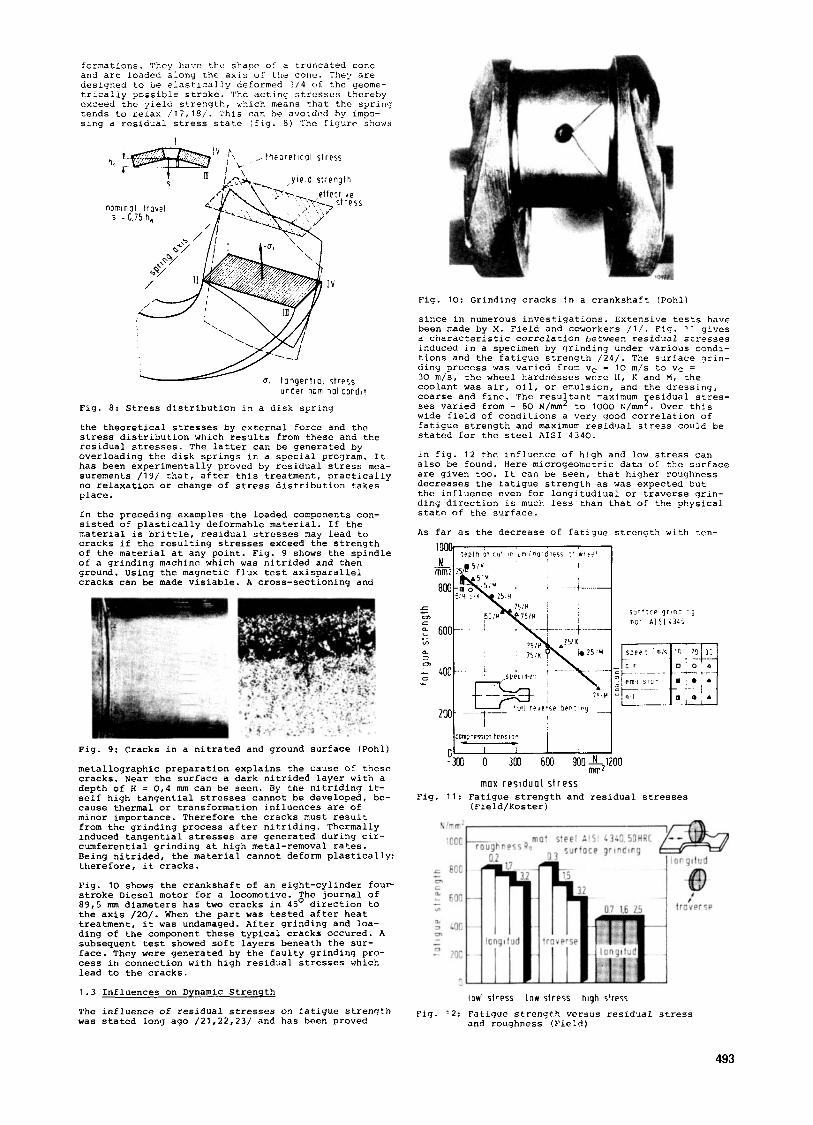
since in numerous investigations. Extensive tests have been made by M. Field and coworkers / l / . Fig. 1 1 gives a characteristic correlation between residual stresses induced in a specimen by grinding under various condi- tions and the fatigue strength / 2 4 / . The surface grin- ding process was varied from vc = 10 m/s to vc = 30 m/s, the wheel hardnesses were 11, R and M, che coolant was air, oil, or emulsion, and thc dressing, coarse and fine. The resultant maximum residual stres- ses varied from - 80 N/m2 to 1000 N/mm2. Over this wide field of conditions a very good correlation of fatigue strength and maximum residual stress could be stated for the steel AISI 3 3 4 0 .
In fig. 12 the influence of high and low stress can also be found. Here microgeometric data of the surface are given too. It can be seen, that higher roughness decreases the fatigue strength as was expected but the influence even for longitudiual or traverse grin- ding direction is much less than that of the physical state of the surface.
As far as the decrcase of fatigue strength with ten-
Fig. 9: Cracks in a nitrated and ground surface (Pohl)
metallographic preparation explains the cause of these cracks, Near the surface a dark nitrided layer with a depth of H = 0 , 4 mm can be seen. By the nitriding it- self high tangential stresses cannot be developed, be- cause thermal or transformation influences are of minor importance. Therefore the cracks must result from the grinding process after nitriding. Thermally induced tangential stresses are generated during cir- cumferential grinding at high metal-removal rates. Being nitrided, the material cannot deform plastically: therefore, it cracks.
Fig. 10 shows the crankshaft of an eight-cylinder four stroke Diesel motor for a locomotive. The journal of 89,5 nun diameters has two cracks in 45O direction to the axis /20/. When the part was tested after heat treatment, it was undamaged. After grinding and loa- ding of the component these typical cracks occured. A subsequent test showed soft layers beneath the sur- face. They were generated by the faulty grinding pro- cess in connection with high residual stresses which lead to the cracks.
1 . 3 Influences on Dynamic Strength
The influence of residual stresses on fatigue strength was stated long ago / 2 1 , 2 2 , 2 3 / and has been proved
max r e s i d u a l s t r e s s Fig. 11: Fatigue strength and residual stresses
(Field/Poster)
l o w stress l o w stress high stress
and roughness !Field) Fig. 12: Fatigue strength vcrsus residual stress
493

alar resJlt for hardened carbon steel Ck 45. Yet he stated that a heat treatment also had stronq influence. The dcpendency was much less or could not bc found fo r mild steel /26/.
The fatiyue fracture of the tested parts started at the weakest point. Thus, not the avcrage value of the stress but the local extreme is relevant. This is es- pecially important for thqse machininy processes which yeneratc scattering stress distributions. For example, Field and Prevey found strong variations in grindiny process with aluminium oxide wheels /27/.
The effect of residual stresses and faulty grinding operations can be seen from gear tests /28,29/. Gcars of casehardened steel 16 Mn Cr 5 were ground on a teeth grinder using normal conditions and conditions which lead to burning (fig. 13). Although no cracks
c y c l e s N
y r b o t o cr i 'er ton !rtcl ion wear r : 5 m m 3 .Z;lrnrr
Fig. 13: Flanc load capacity and grinding process
were generated, the durable flank pressure was de- creased by 25 %. The same investigation showed that with these unfavourable grinding conditions the resi- dual stresses in the surface of the tooth flank in the axial and the radial direction were highly tensile.
( Kosche )
1.4 Chemical Resistance
If certain metals are subjected to stresses and are exposed to a corrosive environment over a period of time, stress corrosion can be observed. The conditions under which this effect arises are a specific sensi- tivity of the material, the existence of tensile stresses in the surface and the presence of a corro- sive medium. Fig. 14 shows the surface of austenitic chronium-nickel steelafter tension in a solution of sulphuric acid and sodium chloride. The cracks are due to stress corrosion. There are different theories
Fig. 14: Stress corrosion in a chromium-nickel steel
about the dominant process during stress corrosion. The electrochemical hypothesis assumes potential dif- ferences between the precipitations at the grain boun- deries or in the grains and the adjacent matrix so that the precipitates are dissolved anodically. Ten- sile stresses open cracks developed in this way. They rupture the surface film in the crack root and bring pure metal to the corrosive environment. Stress corro- sion is one of the main causes of failures in chemical plants (fig. IS) /30/. During a period of one year, 60 % of the occuring failures in a large chemical com- pany were caused by corrosion. More than 20 % of the
60% cor ros ion
corros ion f o l l u r e s Fig. 15: Failure statistics of metal structures
in a chemical plant (Gramberg/Horn)
corrosion defects were detected as stress corrosion.
1.5 Magnetization
The magnetic properties of a ferromagnetic body depend on its physical state. In many applications these de- pendencies are used for measuring and testing purposes. Microcracks for instance act as a disturbance of the magnetic flux in a material. Therefore the flux distri- bution or the flux intensity can be used to detect such faults in the surface or inside the body. Magne- tization effects can also be used to investigate chan- ges in the crystallographic structure of a ferro mag- netic material. The coercive force, for instance, is very sensitive to hardening effects and can be used for in-process-measurements during machining opera- tions.
The magnetic properties are directly influenced by residual stresses and local disturbances of the crys- tallographic structure. Fig. 16 shows the texture of a soft magnetic nickel alloy and its application in a magnetic head of a machine /31/. The information den- sity on the tape is determined by the focusablity Of the head. This is dependent on,the width of the un-
Fig. 16: Magnetic head textures of the
disturbed zone including the air gap between the two poles. The surfaces on the poles have to be machined by lapping. In fig. 16 the deformed grains of these surfaces after electropolishing a thin layer of 13 um and after removing 50 um can be seen. The upper laler shows distinctive con4rasts inside the grains. These are due to local dislocations (local tilts of the lattice /31/). The soft magnetic properties of the material and thereby the focusability of the head are degraded by these mechanical influences.
nickel alloy (ref. : Spur/Bzan)
2. The Nature of Stresses and Residual Stresses
In fig. 17 a body is subjected to external forces L1, L2,..., L6. To describe the internal state of the structural material, the cross-section principle is used. It is assumed that the body is divided into two parts. By this dissection internal forces are set free, which are continously distributed over the cross sec- tion. Considering one of the two parts, the forces on the cross section have to be applied to keep it in the
494
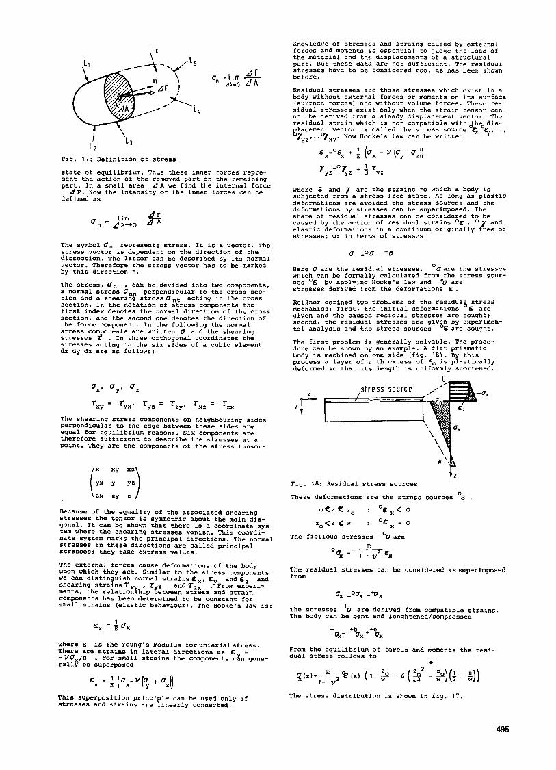
Fig. 17: Definition of stress
state of equilibrium. Thus these inner forces repre- sent the action of the removed part on the remaining part. In a small area d A we find the internal force
d F . Now the intensity of the inner forces can be defined as
The symbol Un represents stress. It is a vector. The stress vector is dependent on the direction of the dissection. The latter can be described by its normal vector. Therefore the stress vector has to be marked by this direction n.
The stress, 4, , can be devided into two components, a normal stress Unn tion and a shearing stressUnt section. In the notation of stress components the first index denotes the normal direction of the cross section, and the second one denotes the direction of the force component. In the following the normal stress components are written U and the shearing stresses 7 . In three orthogonal coordinates the stresses acting on the six sides of a cubic element dx dy dz are as follows:
perpendicular to the cross sec- acting in the cross
TXY = TYX' Tyz = TZY, T x z = Tzx
The shearing stress components on neighbouring sides perpendicular to the edge between these sides are equal for equilibrium reasons. Six components are therefore sufficient to describe the stresses at a point. They are the components of the stress tensor:
Because of the equality of the associated shearing stresses the tensor is symmetric about the main dia- gonal. It can be shown that there is a coordinate sys- tem where the shearing stresses vanish. This coordi- nate system marks the principal directions. The normal stresses in these directions are called principal stresses: they take extreme values.
The external forces cause deformations of the body upon which they act. Similar to the stress components we can distinguish normal strainsBx, and&, and shearing strains T, , TYz ments, the relationghip between stress and strain components has been determined to be constant for small strains (elastic behaviour). The Hooke's law is:
and T z x :'From experi-
1 E x = H U ,
where E is the Young's modulus foruniaxialstress. There are strains in lateral directions as & = - U U /E rall? be superposed
. For small strains the components cxn gene-
Knowledge of stresses and strains caused by external forces and moments is essential to judge the load of the material and the displacements of a structural part. But these data are not sufficient. The residual stresses have to be considered too, as has been shown before.
Residual stresses are those stresses which exist in a body without external forces or moments on its surface (surface forces) and without volume forces. These re- sidual stresses exist only when the strain tensor can- not be derived from a steady displacement vector. The residual strain which is not compatible withoth%dis- glacement vector is called the stress source 4( F,. . , rYz,. .vxy. NOW Hooke's law can be written
Ex'"Ex + ; [ux - v (uy+ U Z ) )
7yz=07yz + TYZ
where E and 7 are the strains to which a body is subjected from a stress free state. As long as plastic deformations are avoided the stress sources and the deformations by stresses can be superimposed. The state of residual stresses can be considered to be caused by the action of residual strains O E , elastic deformations in a continuum originallyo&ee of stresses: or in terms of stresses
and
u =oo- +o
Here (7 are the residual stresses, OU are the stresses which can be formally calculated from the stress sour- ces O& by applying Hooke's law and '0 are stresses derived from the deformations E .
ReiBner defined two problems of the residua& stress mechanics: first, the initial deformations & are given and the caused residual stresses are sought: second, the residual stresses are given by experimen- tal analysis and the stress sources OE are sourht.
The first problem is generally solvable. The proce- dure can be shown by an example. A flat prismatic body is machined on one side (fig. 18). By this process a layer of a thickness of is plastically deformed so that its length is uniformly shortened.
s t r e s s s o u r c e
Fig. 18: Residual stress sources
These deformations are the stress sources "& . o < z < zo : O E X < 0
z o < z < w : OEx = 0
The fictious stresses "U are
The residual stresses can be considered as superimposed from
The stresses The body can be bent and lenghtened/compressed
'U are derived from compatible strains.
+ +b +e q= ox+ ox
From the equilibrium of forces and moments the resi- dual stress follows to
0
This superposition principle can be used only if stresses and strains are linearly connected.
The stress distribution is shown in fig. 17.
495

The second problem - the determination of Stress sodr- ces from measured residual stresses - cannot he solved without turther information, although it seems to be simply the inverse of the first problem. It can easily be seen, however, from the solution of ti-e first pro- blem, that any initla1 deformatlon d & can be added to the given state & without affectinq the residual stress distributior., if these additional cleformations can be derived from a compatible displacement vector. This is, for instance, a constant deformation over the whole cross section from z = 0 to z = x .
In machining processes and by heat treatment the stress sources can be generate2 by mechanical, thermal and transformatlon means (fig. 1 9 ) . If a cylindrlcal specimen is heated below the A,, level and then qaen- ched, the stress distrlbutlon is axisymmetric. The
Z 1
Z 2 2
\. I / htnh \
thermal stresses thermo! siresses lronsformotion mech stressps in solid cylinder in hollow cyl ind stresses b y drawing
Fig. 19: Typical residual stress distributions
shear stresses TZx are negligible. The axial and tan- gential stress components show compression in the sur- face which changes to the inner part. If a hollow cylinder is treated in the same way, the stress dis- tribution is analogous taking into consideration the cooling from outside and inside. Entirely different stress distributions can be obtained if the stresses are generated by crystallographic transformations. Biihler and Scheil heated a high alloyed steel with 1 1 , 7 a Ni to austenitizing temperature of 900°C and cooled it slowly to 36OoC, slightly above the austc- nite-ferrite transformation. Then the specimen was quenched in iced water. The transformation occurs first in the outer domain. The transformation is followed by an increase of volume. Thus compression is generated near the surface and tension is generated in the inner domair.. Inside, the material deforms plastically. After the whole body has reached low temperature the outside domain contains compressive stresses, while the inside contains tensile stresses.
Different stress distributions can also be generated by mechanical treatment - for instance by drawing. Using dies with high reduction of cross section, ten- sile stresses are created in the outside domain and compressive stresses are created in the inside domain. If the work material has undergone another drawing process with only a very small reduction of area in the layers near the surface, compressive stresses are generated. By a specific combination of drawing steps the residual stress level can be mechanically lowered.
t n e t m o l g e n e r o 1 , o n t h e r m a l g e n e r o l l o n
The phenomenon of stress generation can be followed over time. Fig, 2 0 shows three generating systems: a rolling process, where the tool generates compressive strcsscs near the surface; a grinding process, where the surface is heated, and a quenching process with water cooling.
Residual stresses are mechanically generated by rol- ling. The roll is pressed on the workpiece thereby creating compressive stresses in the first stage of the magnitude of the yield strength. Behind the roll high tensile stresses are acting in the rolling di- rection. The material is plastically deformed. After the rolling process the surface layers are, without external forces, "too long" compared with the inside material. Compressive residual stresses are found in the surface layers, and lower tensile stresses are found inside the workpiece. The stress generation by drawing with little reduction of diameter is similar to this system.
Grinding with high metal removal rates and conven- tional grinding wheels quickly heats the surface. Com- pressive stresses are generated. At the same time the yield strength is lowered so that the material is plastically deformed under the influence of compres- sive stresses. Then the temperature decreases and the surface layers are "too short". Tensile residual stresses are generated.
Quenching creates a temperature gradient during the stress generating phase that is opposite to the above mentioned grinding process. It is assumed that no transformations of the fast cooled metal take place. During the cooling period the material near the sur- face shrinks, the inside material with low yield stress is plastically compressed. After temperature compensation, the inside layers are "too short", i.e. compressive stresses remain near the surface and ten- sile stresses remain inside. Thus, it is shown that by thermal impact tensile as well as compressive stresses can be generated. The governing condition is the temperature gradient during the residual stress determining phase.
3 . Measurement
3 . 1 Methods
In many cases a classification of the measuring met- hods tor residual stresses has been proposed as de- structive or nondestructive. For a residual stress- depth-analysis all methods, however, require a partial or complete destruction of the specimen: therefore, a distinction as to direct and indirect measuring met- hods is more effective / 2 . 3 2 / .
For the indirect methods the equilibrium of forces and moments has to be disturbed so that the resulting de- formations of the analyzed body or the removed part deliver the stresses which are of first order.
The direct methods involve determination of stresses by measuring physical properties of the body which can be influenced by stresses. Deformation of the specimen is not necessary.
3 . 1 . 1 Indirect Methods
The first indirect method was proposed by Cilley / 3 3 / for measuring the deformation of parts which are re- moved from the body to be analyzed. Due to the re- maining stresses in the removed parts the results are, however, faulty. The remaining stresses decrease with the size of the divided parts, but the difficulty of measuring the deformations increases.
The problem can be overcome by measuring the deforma- tion of the remaining part. The methods described by Sachs / 3 4 / and Heyn and Bauer / 3 5 / for cylindrical shapes of specimens as well as the formulas of Stlb- lein / 3 6 / and Treuting and Read / 3 7 / for rectangular bodies are well known.
Simple shapes of specimens are chosen to keep the cal- culation effort small.
An approved method for practical application is the de- flection method / 2 , 3 2 / which has been applied for plates and cylinders. If machining stresses have to be determined the surface layers of the specimen are re- moved at the machined side while the deformations of the remaining part have to be measured as a function of thickness. For rectangular plates this principle is shown in fig. 2 1 . If the principal directions of the residual stresses are known it is sufficient to measure the strains in just those directions. The stresses can be calculated according to:
Fig. 2 0 : Types of residual stress generation
496

the application is restricted due to the fact that not only resiuual stresses but also the structure, compo- sition, hardness, texture, density as well as electric and magnetic properties have their influence upon the test results. Nevertheless, if these methods can be developed further, there should be a chance to apply them For "in-process-stress measurement".
Residual stress analysis by X-ray diffraction depends ipon the measurement of strains as is the case fo r most of other methods. The main difference from indi- rect methods is that no macroscopic strains but latti- ce strains, i.e. distances between atoms, must be de- termined. Brayg described X-ray diffraction as a selec- tive reflection according to the law
stressed mull1 crystal mul l1 c r y sto- ."*', '
0 8
W
s p e c i m e n #/
A = 2 d s i n 8
with the wave length of X-rays A , the lattice spacing d and the diffraction angle e . The basic research work for the stress analysis was done by Aksenov /50/. Fig. 2 3 shows the diffraction at a single crystal without and with loading. It is evident that the diffraction angle (3' in the unstressed condition has
E - d e f l e c t i o n w - t h i c k n e s s
Fig. 2 1 : Deflection method
with the thickness of the specimen w and the depth beneath surface (w - 2 ) . Electropolishing is recommen- ded for removing layers since this method induces practically no new stresses. The deformation of the specimen during the removal process can be measured by strain gauges /2/, mechanical or inductive sensors / 3 0 - 4 0 / , or by interferential methods / 2 / . For each case it is essential to measure the deflection in sufficient directions to describe the biaxial surface stress condition completely.
An experimental set up for the stress analysis of ma- chined plates is shown in fig. 22. If the process con- trol and the evaluation of data are done online with
Fig. 2 3 : X-ray diffraction at an unloaded
to be increased to (en + 4 e ) in order to receive in- terference with a maximum intensity at the detector in the loaded condition.
For technical materials which are polycrystalline, the lattice spacing d has to be determined for various grains which have the orientation Cy relative to the specimen surface (fig. 2 4 ) . This is possible for angles with - SO0< Cy < + SO0. By a mathematical extra- polation the lattice strains for Cy = 90° can be cal- culated / 5 1 , 5 2 / . The stresses in this direction are to be determined. By setting the lattice strains equal to those which the theory of elasticity would deliver for a biaxial surface stress condition, the basic equation of X-ray stress measurement results. Fig. 25 shows that in this case the lattice strains & are a linear
and a loaded single crystal
m m p r o c e s s i n g r e g u l o t l n g I c o n t r o l l i n g
Fig. 22: Experimental set up for the deflection method 1 I
stress-free multi crystal a computer, a complete analysis of subsurface stresses up to 2 0 0 um can be accomplished in 3 0 minutes / 4 1 / .
Due to the differentiation, the calculation process is very sensitive to any stochastic influence upon the measured strains. Therefore an exact temperature control during the polishing process is absolutely necessary.
3 . 1 . 2 Direct Methods
From all direct techniques for residual stress analy- sis the X-ray method is mainly applied because of the high state of development and the wide range of ex- perience / 4 2 - 4 4 / . Other direct methods with advanced degrees of development are the magnetic and ultrasonic methods, the application of which are, however, re- stricted to a few cases up till now. Electromagnetic methods are based on the stress dependence of electri- cal conductivity and magnetic properties of ferromag- netic materials / 4 5 - 4 7 / . The ultrasonic methods depend in principle upon the fact that the propagation of ultrasound in a solid medium is influenced by the state of strain of the medium / 4 5 , 4 6 , 4 9 / . The advan- tage of both principles is the extremely short mea- suring time of a few seconds. In many cases, however,
/
Fig. 2 4 : X-ray diffraction at a multi crystal
function of sin'v . The factor 1 / 2 s 2 is called the x-ray elastic constant and has to be determined for the analyzed material in tensile or bending tests / 4 3 , 5 3 / . It must be pointed out that this factor is not only dependent on the material but also on the heat treatment, plastic deformation and the radiation of X-rays / 5 4 - 5 0 / .
The lattice strains & can be calculated from the Bragg equation. This affords a very exact calculation of the peak positions from the diffracted intensities
497

' l a t t i c e p l a n e s d , 3,
L s p e c i m e n s u r f a c e
, I . . ., _).. . .
Fig. 25: Strain ellipsoid for a two axial stress condition and s i n 2 v method Fig. 26: Slope method
makes it possible to determine stress distributions for different anglesv . Several methods are available for this task /41,43,59-64/. Because of the little computation effort the parabola method /59/ and the centre of gravity method /43/ are used in most of the cases. A new technique is given by the cross correla- tion method /41,65/, which has essential advantages especially for computer controlled X-ray stress analy- sis /41,53/.
For certain machining operations, especially those with a high degree of plastic deformation at the sur- face, t e above mentioned linear dependence of & ver- sus sin is not oberserved /43,66,67/. This is due to a triaxial state of stress within the depth of pe- netration of the X-rays which is 5-20 um. In these cases the multi Cv -angle-method has 40 be applied. A goniometer set-up is necessary which is capable of measuring peaks for positive as well as negasivev - angles. If the distribution of & versus sin v/ is similar to an elliptic course, as it is very often the case for ground surfaces /68-70/, the evaluation method of Dalle and Hauk /71/ is suggested. The re- sult is the complete stress tensor with nine compo- nents.
Besides the mentioned (V-splitting there are also other nonlinear distributions possible which are not of a systematic nature. Surface texture is responsible beneath the surface automatically (fig. 27). Good for those effects and no evaluation method has yet agreement between the stepwise and the slope methods been devised. has been shown /41,53/.
4
Fig. 27: Computer controlled setup for a stress-depth analysis with application of the slope method
The X-ray method has advantages compared with the de- flection method such as the feature of nondestructive surface measurements, variable measuring area, and the possibility for repeating measurements. On the other hand one essential disadvantage is the high time con- sumption. Using a goniometer with a proportional de- tector the measuring time for one stress value can be several hours. In recent years, however, several new ways have been shown to speed up the measurements:
A further way to decrease the measuring time is the use of a position sensitive detector (PSD) instead of the conventional proportional counter /73-76/. While it is necessary for the proportional counter to scan the detector with the receiving slit along an arc in order to measure the diffraction peak intensity step- wise, this is not the case for the PSD which receives the entire peak at one shot (fig. 2 8 ) . The high cost of this equipment should not restrict the application
- v) c OJ - - -iL!!L 5
1. Automatic control of the measuring I process and the evaluation by computer
I
2. Determination of subsurface stresses by the slope method 5
28, 28 3. Use of a position sensitive detector (PSD) 28. 28, 28
.~ 28, 28 28, 28
Computer controlled X-ray systems have been developed with different degrees of automation /41.72/. The simplest standard is a goniometer control in order to measure one peak automatically. A high degree of developmenet was reached by a linkage of the gonio- meter with digital computers /41/. Several measure- ments with job cues for different tasks are possible avoiding any type of slack time. Sample changers as well as turning and moving setups for the specimens have been installed.
Another time-consuming procedure is the determination of subsurface stresses by X-rays. Commonly the stress distribution as function of depth beneath the surface layer is determined by alternating stepwise electropo- lishing and measuring.
x - m y tube
I-GjZKiZ]
position sensit ive detector
rneosur ing
Y .. a-roy tube
b u r e r n with fixed psdl
Fig. 28: Principle of a PSD
in the production process because the overall measu- ring time can be decreased at least 10 times.
This method has two disadvantages, first, the operator must remove the specimen from the diffractometer for the etching procedures and clamp it again for the next measurement which means a loss of time. and se- cond, it is impossible to repeat measurements later on, once the specimen has been etched. The slope etching method, which has been developed for this pur- pose, is highly advantageous /41,53/. Fig. 26 shows the principle and the generation of the slope. An ap- plication with computer controlled X-ray equipment
498

M E T C U T
3.2 Reliability and Results')
To get an indication of the accuracy of the measure- ment, several samples were identically treated. They were ground in the same clamping on a surface grinder. The heat treatment and the grinding conditions are given in fig. 29. The deflections were determined by
L A M R E S UNlVCALlf W Z L I I F W
I m a t e r i a l 1
g o n i o m e t e r
r o d i o t i o n
I g r i n d i n g condit ions1
0 R R R R
CrKa(2 l l l CrKal211) CrKo(211) CrKa(2t l i CrKal2l l )
Do:: k c r i n g r!eel 131 Cr 6 s u r t o c e g r l n d i n g
normoiced !o 220 HB I A I - 3 0 0 . 50 - 1 2 7 - A r 6 - I O t 8 - V Ogenched 850' C 1 1 MIn In oli
l V L U l spot l m m 1 3 .3
s i n g l e p o i n l d i o n o n d dresser
vc, : I0 m/s
Ie, : 0.1 nm
0, : 10 rm
L O .bO - 4 mm' dimensions 0 1 s p e c i m e n
3 . 3 2 = 3 0 3.10
Fig. 29: Material and grinding conditions of the round robin test specimen
the indirect method using strain gauges. The scatter from five analyzed specimens and the average stress are shown in fig. 30. These results reflect the influ- ences of material inhomogenities.
Several specimens of the identically treated samples, were also chosen for a round robin test in which se- veral scientists in different countries participated. This test was proposed and carried out by the STC"S" of CIRP in order to find out the reliability of to- day's standard and state of the art in residual stress measurement. Both, indirect and direct methods were applied. Three groups were able to carry out indirect measurements, using the deflection method. The results are shown in fig. 31. It is evident, that not only the
1200 mot tWCr6 surloce QflndinQ A 4 6 J o t 8 i v, = 30 mis . v,,: 4OOmls o I 7 y m stress porollel to grinding direction
depth z [ pm I
Fig. 30: Scatter of residual stress
principal stress distribution but also the quantita- tive values show an excellent agreement. It has to be pointed out again that not only material and machining inhanogenities but also different setups of the parti- cipating groups had their influence on the results. As an example, it should be mentioned that Hannover and Ljubljana used strain gauges for the measurement of deflection while Leuven applied mechanical sensors. The X-ray users carried out surface measurements on a single round robin specimen. All of the five partici- pants employed an Q-goniometer using CrK-radiation. The X-ray elastic constant had been determined by a bending test in one laboratory and the values was given to the participants. The measurement technique of the institutes was different in some points. While
1)
measurement (indirect method)
The results are taken from a cooperative piece of work of STC"S" of CIRP on "residual stress measurements" in which the following scientists participated: M r . J.B. Bryan, Livermore, Dr. M. Field, Cincinnati, Prof. W. Kenig, Aachen, Prof. P. Leskovar, Ljubljana, Prof. J. Peters, Leuven, Prof. B.K. Tenshoff, Hannover
I I I I
p e a k s h l f t 5 -po in t 5-point 3-point centre of d e t lporabola I m r a b o l a ~ o a r a b o l a / a r a v i t v lroacorrF
Fig. 32: Data of X-ray stress measurement
c
P - 0 0 r m
mat tmcr6 62HRC surl grinding AL6 J8V
v - 3 0 m l s
o 8 7 y m X-Roy s d meosurem rod CrKuIZII) ~ Z s . = L E IG5mm.,N
Fig. 33: Comparison of X-ray stress measurement
499
m s I 'OGCr6 6 1 H P I
depth beneath surf3:P z I ym I
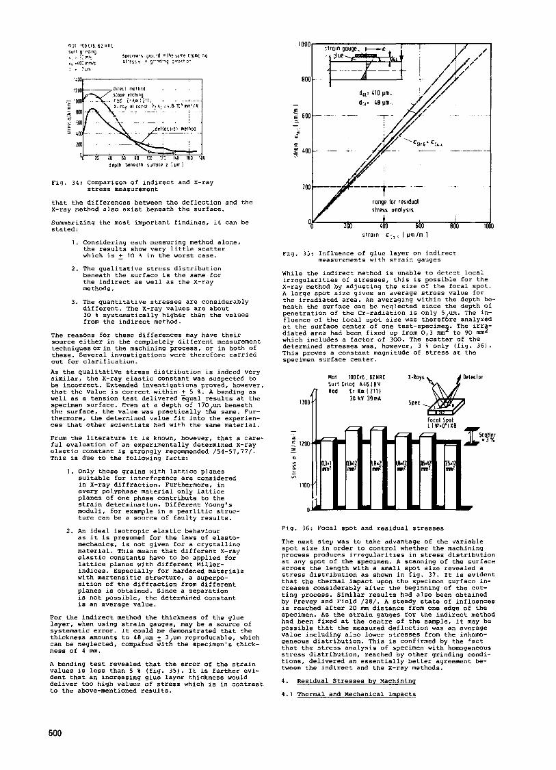
Fig. 34: Comparison of indirect and X-ray
that the differences between the deflection and the X-ray method also exist beneath the surface.
Summarizing the most important findings, it can be stated:
stress measurement
1 . Considering each measuring method alone, the results show very little scatter which is 2 10 % in the worst case.
2 . The qualitative stress distribution beneath the surfacc is the same for the indirect as well as the X-ray methods .
3 . The quantitative stresses are considerably different. The X-ray values are about 30 % systematically higher than the values from the indirect method.
The reasons for these differences may have their source either in the completely different measuremcnt techniquesorin the machining process, or in both of these. Several investigations were therefore carried out for clarification. As the qualitative stress distribution is indeed very similar, the X-ray elastic constant was suspected to be incorrect. Extended investigations proved, however, that the value is correct within 5 %. A bending as well as a tension test delivered equal results at the specimen surface. Even at a depth of 170 um beneath the surface, the value was practically tAe same. Fur- thermore, the determined value fit into the experien- ces that other scientists had with the same material.
From the literature it is known, however, that a care- ful evaluation of an experimentally determined X-ray elastic constant is strongly recommended /54-57,77/. This is due to the following facts:
1 . Only those grains with lattice planes suitable for interference are considered in X-ray diffraction. Furthermore, in every polyphase material only lattice planes of one phase contribute to the strain determination. Different Young's moduli, for example in a pearlitic struc- ture can be a source of faulty results.
as it is presumed for the laws of elasto- mechanics, is not given for a crystalline material. This means that different X-ray elastic constants have to be applied for lattice planes with different Miller- indices. Especially for hardened materials with martensitic structure, a superpo- sition of the diffraction from different planes is obtained. Since a separation is not possible, the determined constant is an average value.
2. An ideal isotropic elastic behaviour
For the indirect method the thickness of the glue layer, when using strain gauges, may be a source of systematic error. It could be demonstrated that the thickness amounts to 48 um 5 3 um reproducable, which can be neglected, compaLed w i d the specimen's thick- ness of 4 mm.
A bending test revealed that the error of the strain values is less than 5 8 (fig. 35). It is further evi- dent that an increasing glue layer thickness would deliver too high values of stress which is in contrast to the above-mentioned results.
I
Fig. 35: Influence of gluc layer on indirect
While the indirect method is unable to detect local irregularities of stresses, this is possible for the X-ray method by adjusting the size of the focal spot. A large spot size gives an average stress value for the irradiated area. An averaging within the depth be- neath the surface can be neglected since the depth of penetration of the Cr-radiation is only 5 um. The in- fluence of the focal spot size was therefbre analyzed at the surface center of one test-specime The irra- diated area had been fixed up from 0.3 mm4'to 90 nun2 which includes a factor of 300. The scatter of the determined stresses was, however, 3 % only (fig. 361. This proves a constant magnitude of stress at the specimen surface center.
measurements with strain gauges
Hal 100Cr6. 6 2 H R C 1-Roys a, Delector Surf h i n d A L 6 l 9 V ,,oo[ Rod Cr Ka 1 2 1 1 )
Spec 30 kV 3 0 m A
Fig. 36: Focal spot and residual stresses
The next step was to take advantage of the variable spot size in order to control whether the machining process produces irregularities in stress distribution at any spot of the specimen. A scanning of the surface across the length with a small spot size revealed a stress distribution as shown in fig. 37. It is evident that the thermal impact upon the specimen surface in- creases considerably after the beginning of the cut- ting process. Similar results had also been obtained by Prevey and Field / 28 / . A steady state of influences is reached after 2 0 mm distance from one edge of the specimen. As the strain gauges for the indirect method had been fixed at the centre of the sample, it may be possible that the measured deflection was an average value including also lower stresses from the inhomo- geneous distribution. This is confirmed by the fact that the stress analysis of specimen with homogeneous stress distribution, reached by other grinding condi- tions, delivered an essentially better agreement be- tween the indirect and the X-ray methods.
4 . Residual Stresses by Machining
4 . 1 Thermal and Mechanical Impacts
500
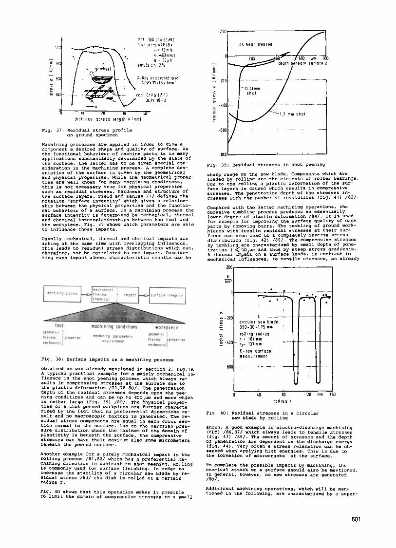
10 20 30 cn- d i s t a r c e g c r c s s iergtb A : m m l
Fig. 37: Residual stress profile on ground specimen
Machining processes are applied in order to give a component a desired shape and quality of surface. As the functional behaviour of machine parts is in many applications substantially determined by the state of the surface, the latter has to be given special con- sideration in the machining process. A complete des- cription of the surface is given by the geometrical and physical properties. While the geometrical proper- ties are well known for many machining conditions, this is not necessary true for physical properties such as residual stresses, hardness and structure of the surface layers. Field and Kahles /1/ defined the notation “surface integrity” which gives a relation- ship between the physical properties and the functio- nal behaviour of a surface. In a machining process the surface integrity is determined by mechanical, thermal and chemical interrelationships between the tool and the workpiece. Fig. 37 shows which parameters are able to influence those impacts.
Usually mechanical, thermal and chemical impacts are acting at the same time with overlapping influences. This leads to residual stress distributions which can, therefore, not be correlated to one impact. Conside- ring each impact alone, characteristic results can be
0
’0
- 200 01
VI
L &
- D Y - 4 0 0 - 0 -
-600 Fig. 38: Surface impacts in a machining process
obtained as was already mentioned in section 2 , fig.19. A typical practical example for a mainly mechanical iri- fluence is the shot peening process which always re- sults in compressive stresses at the surface due to the plastic deformation /73,78-80/. The penetration depth of the residual stresses depends upon the pee- ning conditions and can be up to 4 0 0 um and more which is rather large (fig. 39) /80/. The bhysical proper- ties of a shot peened workpiece are further characte- rized by the fact that no preferential directions re- sult and no macroscopic texture is generated. The re- sidual stress components are equal in each cross sec- tion normal to the surface. Due to the Hertzian pres- sure distribution where the maximum of the domain of plasticity is beneath the surface, the compressive stresses can have their maximum also some micrometers beneath the peened surface.
Another example for a purely mechanical impact is the rolling process /81,82/ which has a preferential ma- chining direction in contrast to shot peening. Rolling is commonly used for surface finishing. In order to increase the stability of a circular saw blade by re- sidual stress /83/ the disk is rolled at a certain radius r.
Fig. 4 0 shows that this operation makes it possible to limit the domain of compressive stresses to a small
1 - circutar saw blade 3 5 0 ~ 3 O X t , 7 5 mm rollhng r a d i u s r,: 101 mm r I : 137 mm K - r a y surface measurement
. L
L -- __
v @
3s n e a t t r e a t e d
0 I I..
Fig. 39: Residual stresses in shot peening
sharp range on the saw blade. Components which are loaded by rolling are the elements of roller bearings. Due to the rolling a plastic deformation of the sur- face layers is caused which results in compressive stresses. The penetration depth of the stresses in- creases with the number of revolutions (fig. 4 1 ) / 8 2 / .
Compared with the latter machining operations, the abrasive tumbling process produces an essentially lower degree of plastic deformation / 8 4 / . It is used for example for improving the surface quality of cast parts by removing burrs, The tumbling of ground work- pieces with tensile residual stresses at their sur- faces can even lead to a completely inverse stress distribution (fig. 4 2 ) / 8 5 / . The compressive stresses by tumbling are characterized by small depth of pene- tration ( <SO um and thus by steep stress gradients. A thermal impabt on a surface leads, in contrast to mechanical influences, to tensile stresses, as already
I 1 I 0 LO ao 120 mm I60
r a d i u s r
Fig. 4 0 : Residual stresses in a circular saw blade by rolling
shown. A good example is electro-discharge machining (EDM) /86,87/ which always leads to tensile stresses (fig. 4 3 ) /86 / . The amount of stresses and the depth of penetration are dependent on the discharge energy (fig. 4 4 ) . Very often a stress relaxation can be ob- served when applying high energies. This is due to the formation of microcracks at the surface.
To complete the possible impacts by machining, the chemical attack on a surface should also be mentioned. In general, however, no new stresses are generated /80/.
Additional machining operations, which will be men- tioned in the following, are characterized by a super-
501

d P P l C S r F P 3 l n I"r1pCe 2
Fig.41:Residual strcsscs in elements of roller bearings
~ t u m b l p d a f t e r gr I ndi ng
I -
, -
pr n c i p l e p f o b r a i t / P t u a b l i n g
-'*O0o 60 120 8C 2 4 0 prr 300 d P p t P beneath s u r f a c e 7
Fig.42:Residual stresses by abrasive tumbling
'30 2CO 3u Depth below surface Ipm]
Fig. 43: Residual stresses by ED-machlnlng: stress distribution
Fig. 4 4 : Residual stresses by ED-machining:
position of mechanical and thermal influences and thus
discharge energy
Lead to residual stresscs which reach from tension to compression depending on thc machining condition, tool and workpiece material.
Various scientists have developed models which should be able to predict thc sachining residual stresses in :he workpiece. Rather a simple model has been ex- plained by Syren /25/. Syren distinguishes between surfaces which are cut by the tool without a following squeezing an& those, which are sqlleezed and thus plas- tically deformed after the cutting process. Syren states: "Surfaces generated by a cutting operation without a following squeezing have tensile stresses. Tensile stresses shift towards compression if the mag- nitude of the squeezed surface elements increases. High cutting tcmperatures will favor tensile stresses. Blunt cutting tools can also lead to compressive stresses by a bigger surface deformation and can pro- duce tensile stresses because of an increasing of friction." Syren proves this theory by measuring re- sidual stresses produced by different machining pro- cesses. While the model is very suitable to explain f.i. the difrerent stresses produced by up cut milling and down cut milling, it is not sufficient to give a useful description of the conditions in grinding. This special problem had been tackled by Snoeys, Maris and Peters / 80 / . The model Is based upon theresearchwork of Jaeger / 09 / and gives a relationship between the kinematic grinding parameters and the surface tempera- ture of the workpiece. For a given wheel-work-cooling- dressing condition, the influence of the kinematic pa- rameters is governed largely by the variation of the tangential grinding force which determines, together with the grinding speed, the specific energy of the grinding process. Related to the equivalent wheel dia- meter de the force equation can be written
with the force exponent = 0 , 3 < f < 1.0 and the equi- valent chip thickness heq = a . Vft. If f has been determined by the upper equation, the contact tempera- ture T can be calculated principally as follows:
VC
T-.f-0,235 . ft f-0,57 'vC 1,l-f . de 0,765-f
It can be seen that the force exponent f is a parti- cularly important factor, as it reflects the dependen- ce of tangential forces upon the machining parameters and thus upon the temperature rise in the workpiece. An important recognition i s that a single machining parameter is without any influences upon the tempera- ture if the force exponent has a certain value. Fig.45 gives an impression of the qualitative dependence of the temperature from the stock removal rate 2 ' (as a function of workspeed) and the cutting speed for ma- terial-wheel combinations with different f-values. Ma- terials which are difficult to grind are characterized by a low force exponent which leads to high tempera- tures and thus to tensile stresses. It can be shown that the amount of maximum tensile stresses in a ma- chined surface is dependent on the maximum surface temperature /08/ . Fig. 46 demonstrates this relation- ship :or two different types of steels. The influence of structural changes is also evident.
" I
wrkpiccc I rhrrl combmotion aIIIwdI logrind I w 0.31
.wrkDbrcr I whrd
wrkpiccc I rhrrl combmotion aIIIwdI logrind I w 0.31
/ I .wrkDbrcr I whrd
Fig. 45: Maximum surface temperature as function of workspeed and wheelspeed
In the following, different machining operations are analyzed with respect to thermal and mechanical im- pacts and the possibilities are pointed out to in- fluence those impacts, in order to generate dif€erent residual stress distributions.

H/mm'l I
-0 LOO mox s u r l a c e temperature T
Fig. 46: Relationship of temperature effects
4 . 2 Grinding
In grinding operations, randomly distributed abrasive particles of various geometrical forms, varying in their cutting characteristics, produce plastic defor- mations on the surface of the machined parts. The nor- mal pressures produced during grinding are high com- pared with other machining operetions. High tempera- tures and pressures in the zone of interaction be- tween the grains and the workpiece material and heavy plastic deformation of the latter lead to substantial changes of the physical properties. Thus the produced residual stresses are influenced by the following pa- rame ter s :
and residual tensile stresses
machinins conditions (depth of cut a, speed of workpiece vft, cutting speed vc)
topography of the grinding wheel (dressing conditions, wear behaviour)
specification of the grinding wheel (type and size of grains, structure, bond, hardness)
cooling conditions
The influence of the machining conditions has been analyzed by various scientists / 1 , 2 , 2 3 - 2 6 , 4 1 , 9 0 - 1 0 7 / . In most cases conventional aluminium oxide wheels have been applied.
The related material removal rate 2 ' is given by the product of speed of workpiece "ft and depth of cut. These two factors show inverse effects on the machined surface. Increasing the depth of cut leads to higher tangential forces and, thus, to stresses towards ten- sion due to the increased cutting energy. An increased speed of workpiece leads to faster movement of the heat source along the machined surface. For different parameters this behaviour is demonstrated in fig. 47 for plunge grinding / 8 8 / .
plunge grind.ng A 60. t7-v I
depth beneath surface I - 300 I
Fig. 47: Residual stresses after plunge grinding
Since the cutting energy and thus the heat which is produced in the cutting zone are given by the tangen- tial forces and the cutting speed, the latter is a very important parameter also affecting residual stresses. For a titanium alloy, fig. 48 shows that the magnitude of surface stresses is mainly influenced by the wheel speed /go/. The wheel dressing is found
I00 yn Ib 50 arpth Ernei'r r ~ ~ l o : ? I
Fig. 48: Cutting speed and residual stress
ding wheel topography with a great impact upon the grinding wheel topography and thus upon the heat gene- ration in the cutting process. Although it is well known that the dressing conditions are 2 to 3 times more critical than other parameters /90/ only a few investigations have been carried out / 4 1 , 1 0 4 - 1 0 6 / . It can be assumed that different results according to absolute values of residual stresses in grinding with comparable conditions reach back to this influence. rig. 4 9 gives an example of the dressing influence / 4 1 / . Coarse dressing produces a wheel surface that is open and free cutting. On the other hand, a closed grain structure in the wheel results in wheel surfaces that are not free cutting which leads to an increased thermal impact. Tensile residual stresses increase although the surface quality is improved in most cases O f a similar importance is the wear of the grinding wheel / 9 3 , 1 0 4 , 1 0 7 / . Aluminium oxide wheels are espe- cially sensitive to this effect. In many applications a blunting of grains can be detected already after a short grinding time. Fig. 50 / 4 1 / shows that the low stresses after dressing become rather high tensile stress s after a removed workpiece volume of "w' = 100 nun /nun. Furthermore, the influence of the cutting speed increases with the wear. Similar results have been found by Peters / 1 0 7 / .
5
dQplh DQt lcoth rurlocr I
Fig. 49: Dressing conditions and residual stresses
Fig. 50: Residual stresses of grinding wheel
as function wear and
to be a parameter with a great impact upon the grin- cutting speed
503

For residual stress generation, not only is the condi- dion of the wheel whilc in use important, but also the selection of grains, bond, structure and hardness. A soft wheel can require more dressing time, particular- ly in form qrinding; however, it can be advantageous to use because less stress is produced. This is due to the fact that grain blunting, which means heat ge- neration by friction, cannot arise because a grain breaks oat if the tangential force exceeds a certain value. In contrast to the conventional aluminium-oxide wheel, the wear behaviour from cubic boron nitride (CBN) wheels is completely different. This has been proved in surface grinding /41/ and in internal grin- ding /104/. Due to the high hardness of CBN, no blun- ting could be observed with the scanning electron microscope but only splintering which does not re- strict the sharpness. Therefore, less heat arises in the cutting zone with the consequence that only com- pressive residual stresses are produced. With increa- sing CBN-concentration of the wheel, the residual sur- face stresses shift to compression. For comparison purposes, results for an aluminium-oxide wheel are also given in fig. 51. It is evident that constant reliable stresses are produced for a long grinding period.
"1"
'00- - E
Grlndlng Wheel Workpiece O r e s n g d, - 30 mm 100 t r 6 6 2 H R C Oiomont Cup Wheel b. 20 mm d. . 4Omm v = 30 mls v I . . l m l s Coolant 1 ' . 1 mm'lrnms 811
dramatically, especially for high cutting speeds. An important conclusion from this is that while the cooling capability of emulsion which is considerably superior to oil, it is not responsible for an improved surface stress condition. The explanation is that the improved lubrication ability of oil supresses friction- induced generation of heat during the cutting process. Thus the plastic deformations in the cutting zone lead to compressive stresses.
There are several known methods for improving the re- sidual stress conditions of ground surfaces. Most of these methods are finishing operations which rely primarely on plastic surface deformation with little metal removal. One of them is the sparking out proce- dure in the last grinding cycles. Fig. 5 3 /41/ demon- strates that a considerable stress relaxation is achievable by this operation.
Fig. 53: Sparking out and residual stresses
Another finishing method is the abrasive tumbling of ground surfaces which has been explained previously. A procedure which is very often applied by ball bea- ring manufacturers is the honing process. Fig. 54 gives an idea of the honing effect applied on external ground workpieces. The predominant plastic deforma- tions are able to produce high compressive stresses/941
Fig. 52: Grinding fluid and residual stress
504
I I 1 B 12 un I6
deptn Drnrolh s u r l o ~ r I
Fig. 54: Honing of ground surfaces and residual stresses
4 .3 Turning
In turning operations the cutting energy is mainly transformed in the shearing zone. This enables the produced heat to flow not only into the workpiece sur- face but also into the chips. Although the heat which flows off with the chips is greater per volume element than in grinding, tensile residual stresses are domi- nant in turning /2,73,108-111/. This is due to the fact that the machined surface is usually not produced by the main cutting edge but by the secondary cutting edge. It has been proved that the friction induced for- ces and thus the cutting temperatures increase with the tool radius and the cutting speed. A smaller chip thickness and negative cutting angles produce the same result due to higher friction /112/. On the otherhand, a negative cutting angle produces a higher degree of plastic deformation (fig. 55) which results in a de- creasing of surface tensile stresses (fig. 5 6 ) / 2 / .
Not only the mechanical but also the thermal impact increases with the cutting feed fa. This results in higher tensile stresses at the surface and a deeper penetration of stresses into the material (fig. 57) /2/.

Fig. 55: Plastic deformations in turning
Fig. 56: Cutting angle in turning and residual stresses
depth I dep!h 1 deplh z
mat corbon s tee l t (5 v, = Wmlrnin I * 12' r - 0.8 LOCI h o r d nelol K 20 0 * 1.0mm A: 4' x - 5 3 '
Fig. 57: Residual stresses in turning
A further example from practice is the tungsten car- bide tip turning of an aluminium alloy. Tubes with 70 mm diameter had been produced by a manufacturer by cold extrusion. One customer applied those tubes for transferring chemical fluids after having machined the tubes inside as well as outside by turning. A stress corrosion problem arose after some time which could be attributed to the machining operation /lll/. From the tube suitable specimens were cut out and analyzed by.the X-ray diffraction method. Fig. 56 shows the surface stresses of the unmachined as well an the machined tube. It can be seen that the cold extrusion of the manufacturer leads to compressive stresses and negligible tensile stresses, while the turning operation produces considerable tensile stresses.
for different cutting feeds
4.4 Millinq
In milling, considerable plastic deformation is pro- duced, thus the residual stresses tend to be compres- sive / 1 ,2 ,25 ,73 ,108 ,109 ,113 ,114 / . Since the penetra- tion depth of thermal influences upon the surface are smaller than the mechanical impacts, the compressive stresses are reduced at the surface and may even rise to tensile stresses. Typical stress distributions for
Fig. 58: Residual stresses by turning an aluminium alloy tube
face milling are shown in fig. 59 / 1 1 3 / .
Higher cutting speeds and feed rates lead to an in- crease of compressive stresses an8 depth of penetra- tion. In milling, the wear of the cutting tool is of significant influence. The duller the too1,the deeper the compressively stressed layer. In fig. 60 /1/ the sharpness of the tool is characterized by the wear- land. Similar results had been obtained by Yleln /log/ and Syren / 2 5 / . Syren explains different stress di- stributions by means of his developed model conside- ring thermal and mechanical impacts. The model can also efficiently be applied for explaining different residual stress distributions in up cut milling and down cut milling as it has also been proved by Kiethe /114/. In up cut milling a cold cutting edge enters the cutting process with a very small chip thickness. Cold plastic deformations are dominant at themachined surface and lead to compressive stresses. During the further contact length of the tooth, the produced heat increases in those surface layers, which are re-
0 I25 250 175 ym -8m I
dep!h beneath surloce I
Fig. 59: Residual stresses in face milling (Leskovar)
I
I 1W Z@ wn 100 0
900 1 depiP iereo't SUI'PCP I
Fig. 60: Wearland and residual stresses in face milling /1/
505
seen that the zone of plastic deformation with com- pressive stresses is rather small and tensile stresses are produced after a short cutting length as soon as the chip formation is started.
5. Conclusions
Residual stresses in surface layers of amachinedcom- ponent can generate deformations and can influence the static and dynamic strength and the magnetic and che- mtcal properties of the surface. A complete descrip- tion of a machined surface requires, therefore, deter- mination of the residual stress tensor. This tensor can always be considered as caused by the action of residual strains and from strains which are subjected to the compatibility conditions.
In machining processes residual stresses can be gene- rated by mechanical, thermal and transformation cau- ses. Thus, characteristic stress distributions are de- veloped. In practise these causes amalgamate and can vary in wide ranges.
The measurement of residual stresses generated by ma- chining is difficult because of the steep gradients perpendicular to the surface. x-ray (direct measure- ment of lattice spacing) and deflection techniques (indirect measurement) were applied by several1 labo- ratories. The results are in good agreement; yet it has to be considered that the deflection method is an integral measuring procedure whereas the X-ray method needs only a limited measuring spot.
Shot peening and rolling are typical mechanically in- fluencing processes, electro discharge machining (EDM) influences thermally. The characteristic stress dis- tributions were shown: compressive stresses with equal tensor components by shot peening, also compressive stresses by rolling but with distinct principal direc- tions, EDM generates equal tensile components. For other machining processes like grinding, honing, tur- ning, milling and shaping characteristic stress dis- tributions were given.
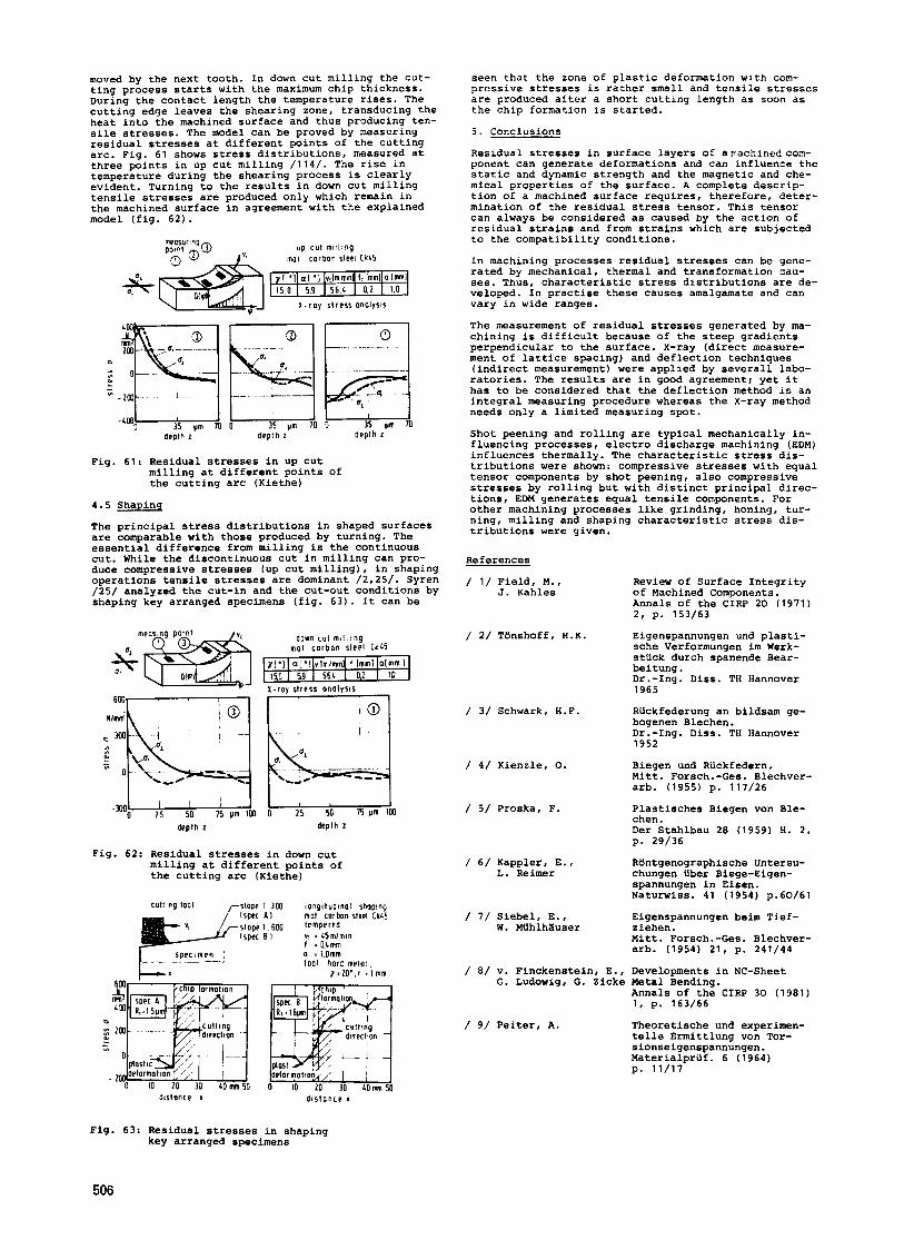
moved by the next tooth. In down cut milling the cut- ting process starts with the maximum chip thickness. During the contact length the temperature rises. The cutting edge leaves the shearing zone, transducing the heat into the machined surface and thus producing ten- sile stresses. The model can be proved by measuring residual stresses at different points of the cutting arc. Fig. 61 shows stress distributions, measured at three points in up cut milling /114/. The rise in temperature during the shearing process is clearly evident. Turning to the results in down cut milling tensile stresses are produced only which remain in the machined surface in agreement with the explained model (fig. 62).
U P c u t m t i l ; n g mecsur~ng
m mot c o r 3 0 n sleet Ck45
x - r o y slress o n o i y s i s
d e p l h 2 d e p t h 2 deplh I
Fig. 61: Residual stresses in up cut milling at different points of the cuttlng arc (Kiethe)
4.5 Shapinq
The principal stress distributions in shaped Surfaces are comparable with those produced by turning. The essential difference from milling is the continuous cut. While the discontinuous cut in milling can pro- duce compressive stresses (up cut milling), in shaping operations tensile stresses are dominant /2,25/. Syren /25/ analyzed the cut-in and the cut-out conditions by shaping key arranged specimens (fig. 63). It can be
References
/ 1/ Field, M., J. Kahles
Review of Surface Integrity of Machined Components. Annals of the CIRP 20 (1971) 2, p. 153/63
Eigenspannungen und plasti- sche Verformungen im Werk- stuck durch spanende Bear-
/ 2/ Tthshoff, H.K. down LUI m i l . i n g m o t c o r b o n sleel Ck45
beitung . Dr.-Ing. Diss. TH Hannover 1965 X - r a y s l r e s s o n o i y s i s
/ 3/ Schwark, H.F. Riickfederung an bildsam ge- bogenen Blechen. Dr.-Ing. Diss. TH Hannover 1952
Biegen und Rilckfedern. Mitt. Forsch.-Ges. Blechver- arb. (1955) p. 117/26
Plastisches Bieqen von Ble-
/ 4 / Kienzle, 0.
0 -00 deplh I
/ 5 / Proska, F. chen. Der Stahlbau 28 (1959) H. 2 , p. 29/36
Fig. 62: Residual stresses in down cut milling at different points of the cutting arc (Kiethe)
/ 6 / Kappler, E., L. Reimer
Rtintgenographische Untersu- chungen Uber Biege-Eigen- spannungen in Eisen. Naturwiss. 41 (1954) p.60/61
Eigenspannungen beim Tief- ziehen. Mitt. Forsch.-Ges. Blechver- arb. (1954) 21, p. 241/44
Developments in NC-Sheet Metal Bending. Annals of the CIRP 30 (1981) 1, p. 163/66
Theoretische und experimen- telle Ermittlung von Tor- sionseigenspannungen. Materialpriif. 6 (1964) p. 11/17
Culllrg tool r S I O D e I 300 i o n o i l u d i n o l s h o o m / 7 / Siebel, E..
W. MUhlhXuser
/ 8/ V. Finckenstein, E., G. Ludowig, G. Zicke
/ 9/ Peiter, A.
dislonce I d i s t o n c e I
Fig. 63: Residual stresses in shaping key arranged specimens
506

/lo/ Polakowski, N.H.
/11/ Peiter, A.
/12/ Schleichsr, F.
/13/ Thiirlimann, B.
/14/ Johnson, W. and others
/15/ Juckel, W
/16/ Bilhler, H. and A. Rose
/17/ Almen, J . O . , A. Laszlo
/18/ LUtZ, 0.
/19/ Schuler, W., H. Walter
/20/ Pohl, E.
/21/ Biihler, H., H. Buchholtz
/22/ Thum, A . , W. Bautz
/23/ Tarasov, L.P., W.S. Hyler, H.R. Letner
/24/ Field, M., W. Koster
/25/ Syren, 0 .
Effect of Residual Stress on Yielding and Strain-Ageninq of Carbon Steel. J. Iron Steel Inst. (1952) p. 369/76
Experimentelle Ermittlung der spannungsverformungskur- ven von Ziehgut mit Eigen- spannungen I. Art. Draht 14 (1963) p. 632/37
Taschenbuch filr Bauinge- nieure Berlin/Gbttingen/Heidelberg 1955
EinfluD von Eigenspannungen auf das Knicken von Stahl- stiitzen. Schweizer Arch. (1957) p. 388/404
Ultra-High Pressure Equip- ment and Techniques Mainly for Synthesizing Diamond and Cubic Boron Nitride. Fortschrittsberichte VDI-Z., Reihe 2, Nr. 37
Beitrag zur Haltbarkeit von einteiligen hohlzylindri- schen Haltbarkeitswerkzeugen Dr.-Ing. Diss. TH Hannover 1970
Darstellung des Entstehens von Eigenspannungen in Werk- stiicken am Stahl in ihren Umwandlungsschaubildern. Arch. Eisenhiittenwesen 40 (1969) p. 411/23
The Uniform Section Disk Spring. Trans. ASME 58 (1936) p. 305/14
Zur Berechnung der Teller- f edern. Konstruktion 12 (1960) H.Z., p. 58/59
Eigenspannungsverteilungen in Tellerfedern aus Stahl. Eigenspannungen, Proceedings of a Symposium Deutsche Gesellschaft f. Me- tallkunde, 1980, p. 131-37
Das Gesicht des Bruches me- tallischer Werkstoffe. Milnchen, Berlin
Uber die Wirkung von Eigen- spannungen auf die Schwing- festigkeit. Mitt. Forsch.-Inst. Verei- nigte Stahlwerke 3 (1933) 8, p. 235/48
Ursachen der Steigerung der Dauerhaltbarkeit gedrlickter Sttibe. Forochg. Ing. Wes. 6 (1935) p. 121/28
Effect of Grinding Condi- tions and Resultant Residual Stresses on the Fatigue Strength of Hardened Steel. Proc. Am. SOC. Test. Mat. 57 (1957) p. 601/22
Optimizing Grinding Parame- ters to Combine High Produc- tivity with High Surface In- tegri ty . Annals of the CIRP 27 (1978) 1, p. 523/26
Der EinfluD spanender Bear- beitung auf das Biegewechsel- verformungsverhaltenvonCk 45 in verschiedenen WBrmebe- handlungszustanden. Dr.-Ing. Diss. Univ. Karls- ruhe 1975
/26/ Konig, W., R. Lowin
/27/ Prevey, P.S., #. Field
/28/ Kosche, H.
/29/ Konig, W., H. Kosche
/30/ Cramberg, U., E.-M. Horn
/31/ Degner, W., T. Lauterlein
/32/ Tonshoff, H.K.
/33/ Cilley, F.H.
/34/ Sachs, G.
/35/ Heyn, E., 0. Bauer
/36/ Stablein, F.
/37/ Treuting. R.G., W.T. Read
/38/ Niku-Lari, A., J.F. Flavenot
/39/ Field, M., J.F. Kahles, J.T. Cammet
/ 4 0 / Peters, J., A. Decneut
/41/ Brinksmeier, E.
Ermittlung des Eigenspan- nungszustandes in der Rand- zone geschljffener Werk- stilcke und Bestimung seiner Auswirkung auf das Funk- tionsverhalten. Forschungsber. Nordrhein- Westfalen Nr. 2886 (1979)
Variation in Surface Stress due to the Metal Removal. Annals of the CIRP 24 (19751 1, p. 497/501
Das schadensfreie Verzah- nungsschleifen von einsatz- gehtirteten Zylinderrtidern am 16 Mn Cr 5. Dr.-Ing. Diss. RWTH Aachen 1976
Das schadensfreie Verzah- nungsschleifen von einsatz- gehlrteten Zylinderrxdern am 16 Mn Cr 5. Techn. Mitteilungen 69 (1976)
Erfahrungen mit SchBdigungen durch gleichmS6ige FlIchen- korrosion sowie selektive Korrosion, Mulden-, Spalt- und Kontaktkorrosion. VDI-Berichte Nr. 243 (1975) p. 75/92
The Determination of Micro- hardness and Residual Stress of Machined Ferromagnetic Components by Using the Bark- hausen Effect. Annals of the CIRP 29 (1980) 1 , p. 403/08
Randzonenbeeinflussung durch Spanen und Abtragen - ein Beitrag zur Anpassung der Analysenmethoden. Annals of the CIRP 23 (1974)
Some Fundamental Proposi- tions in the Theory of Elas- ticity. A Study of Primary or Self-Balancing Stresses. Amer. J. Science 1 1 (1901) 64, p. 269-90
Der Nachweis innerer Span- nungen in Stangen und Rohren. 2 . Metallkunde 19 (1927) 9,
7 / 8 , p. 357/58
1, p. 187-88
p. 352-57
Uber Spannungen in kaltge- reckten Metallen. Int. 2 . Metallographie 1 (19111, p. 1650
Spannungsmessung aneinseitig abgeltischten Knilppeln. Kruppsche Monatshefte 12 (1931) 5, p. 93-99
A Mechanical Determination of Biaxial Stress in Sheet Materials. J. Appl. Phys. 22 (1951) 2, p. 130-34
Hesuredes contraintes resi- duelles sur des surface planes. CETIM-Information NO. 48, Paris 1977
A Review of Measuring Met- hods for Surface Iptegrity. Annals of the CIRP 21 (1972) 2, p. 219-38
Continous Measurement of Re- sidual Stress in Thin Cylin- drical Pieces Using Deflec- tion-Etching Techniques. Report of CRIF, BrUssel 1973
Randzonenanalyse geschliffe- ner Werkstilcke. Dr.-Ing. Diss. Univ. Hannover 1982
507
a
/43/ -
/44/ -
/45/ -
/46/ Huber, H - I R. Mucke
/47/ Theiner, W.A.
/48/ Theiner, W.A.
/49/ Theiner, W.A.
/50/ Aksenov, G.J.
/51/ Hauk, V.
/52/ Macherauch, E., P. Miiller
/53/ Tonshoff, H.K., E. Brinksmeier
/54/ Bollenrath, F., V. Hauk, E.H. Miiller
/55/ Stiiwe, H.P.
/56/ Strlckforth, J.
/57/ Hauk, V., H. Kockelmann
/58/ Krause, H., H.H. Jiihe
Materialprufung rnit Rontgen- strahlen. Springer Verlag 1971
Spannungsermittlung mitR6nt- genstrahlen. HTM 31 (1976) 1 u. 2
Residual Stress Measurement by X-ray Diffraction. SAE-Report J 784 1 , 1971
Proceedlngs of a Workshop on Nondestructive Evaluation of Residual Stress. NTIAC-72-2. San Antonio, Texas 1975
Elgenspannungsmessungen an Kreisslgebllttern mit elek- tromagnetischen Verfahren. Forschungsbericht des Landes NRW, Nr. 2817, 1979
Neue Verfahrensansltze ftir die magnetische und magneto- elastische Gefilgepriifung. Vortrag auf der 4. Int. Kon- ferenz ZFP in der Kerntech- nik, Lindau 1981
Zerstorungsfreier Nachweis von Eigenspannungen mittels Ultraschall-Doppelbrechung und Magnetostriktion. Bericht des IzfP Saarbriicken 1981
Bestimmung von Spannungen mit magnetischen, magneto- elastischen und laufwegunab- hlngigen US-Verfahren. Bericht des IzfP Saarbrticken Nr. 790321-TW, 1979
Measurement of Elasticstress In a Fine-Grained Material. Zeitschr. Angew. PhysikUdSSR 6 (19291, p. 3-16 Ermittlung von Eigenspannun- gen aus rentgenographischen Gitterkonstanten-Messungen. Arch. Eisenhlittenwesen 25
Das sin2v - Verfahren der rantgenographischen Span- nungsmessung. 2. angew. Physik 13 (1961)7, p. 305-12
Optimization of Computercon- trolled X-Ray Stress Analysis Annals of the CIRP, 30 (1981) 1, p. 509-13
Zur Berechnung der vielkrls- tallinen Elastizitltskon- stanten aus den Werten der Einkristalle. 2. Metallkunde 58 (19671, p. 76-82
Mechanische Anlsotropie. Springer Verlag, Wien 1974
Uber den Zusammenhang zwi- schen rhtgenographischer Gltterdehnung und makrosko- plschen elastischen Spannun- gen . Techn. M i t t . Krupp 24 (1966) 3, p. 1-14
RLIntgenographIsche Elastizl- tltskonstanten zur Span- nungsermittlung. Elgenspannungen, Tagungsband
Untersuchung des Gefiigeein- flusses auf die Gr8Be der rentgenographischen Elasti- zitltskonstanten. Forschungsberlcht des Landes NRW Nr. 2623, 1877
(1954). p. 273-78
DGM 1980. p. 241-60
/59/ Koistinen, D.P., R.E. llarburger
/60/ Hauk, V.
/ 6 1 / Hartmann, U.R.
/62/ Parish, W., T.C. Huang, G.L. Ayers
/63/ Rietveld, H.M.
/64/ Sabine, T.M.
/65/ Tanshoff, H.K., E. Brinksmeier
/66/ Hauk, V., W.K. Krug, G. Vaessen
/67/ Dtille, H., V. Hauk
/68/ Hauk, V., W.K. Krug, G. Vaessen, H. Weisshaupt
/69/ Dalle, H., J.B. Cohen
/70/ Hauk, V., R. Oudelhoven, G. Vaessen
/71/ Dtille, H., V. Hauk
/72/ Krause, H., H.H. Jiihe
/73/ -
/74/ Lebrun, J.L., J.M. Sprauel, G. Maeder
A Simplified Procedure for Calculating Peakposition in X-Ray Residual Stress Mea- surements on Hardened Steel. Trans. ASM 51 (1959), p.527- 555
Methoden zur Bestimmung von Eigenspannungen. Eigenspannungen, Tagungsband
Mogllchkeiten und Grenzen der rtlntgendlffraktometri- schen Spannungsanalyse inder Martensit- und Austenitphase einsatzgehsrteter Stlhle. Dr.-Ing. Diss., Karlsruhe 1973
Profilfitting: A Powerful Method of Computer X-Ray In- strumentation and Analysis. Trans. Am. Cryst. ASS. 12 (1976), p . 55-73
A Profile Refinement Method of Nuclear and Magnetic Structures. J. Appl.Chryst. 2, (1969),
DGM 1980. p. 21-39
p. 65-71
Powder Neutron Dlffraction- Refinement of the Total Pattern. J. Appl. Chryst. 10 (1977). p. 277-80
Determination of the Mechani- cal and Thermal Influences on Machined Surfaces by Mic- rohardness and Resldual Stress Analysis. Annals of the CIRP 29 (1980) 2, p. 519-30
Nichtlineare Gitterdehnungs- verteilungen durch verschie- dene Beanspruchungen. 2. Metallkunde 72 (1981) 1, P. 51-58
Systematlk meglicher Gitter- dehnungsvertellungen bei me- chanisch beanspruchten me- tallischen Werkstoffen. 2. Metallkunde 68 (1977) 1 1 , p. 725-28
Der Eigendehnungs-/Eigen- spannungszustand nach Schleifbeanspruchung.
Residual Stresses in Ground Steels. Metallurgical Transaction
Uber die Art der Eigenspan- nungen nach Schlelfen. HTM 36 (1981) 5, p. 258-61
Rhtgenographlsche Spannungs- ermittlung fiir Eigenspan- nungssysteme allgemeiner Orientierung. HTM 31 (1976) 3, p. 165-68
Die Automatisierung vonR6nt- genfeinstrukturmeBplltzen mlt Hllfe eines standardi- sierten Schnittstellensys- tems (IEC-Bus) . HTM 35 (1980) 4, p. 192-98
Scientific Report of ENSAM, Dep.: Mechanics of Materials and X-Ray Diffraction, Paris, 1982
Use of a Position Sensitive Detector. Advances in X-Ray Analysis, 24 (1981), p. 143-48
HTM 35 (1980) 3, p. 144-47
ASME (1980)11, p. 159-64
508
/75/ Clayton, O.R.
/76/ Smith, D.K., K.L. Smith
/77/ Hanke, E., K.-W. Marx
/78/ Koster, W.P., L.R. Gatto, Z.T . Cammett
/79/ MC Clinton, J.B. Cohen
/ 8 0 / Field, M.
/El/ Gerlach, H.H.
/82/ Weck. M.
/83/ Hackenberg, P.
/84/ Wittmann, K.
/85/ Field, M., J.F. Cales
/86/ Schnwhl, H.P.
/07/ Jutzler, W.I.
/ 8 8 / Snoeys, R., M. Maris, J. Peters
/09/ Jaeger, J.C.
X-Ray Analysis and Advances /91/ Lowin, R . in Portable Field Instrumen- tation. Journal of Metals (1979) 6, p. 10-15
/92/ Konig, W. X-Ray Diffraction. Analytical Chemistry 54 (19821, p. 156-65
/93/ Matalin, A.A. Rontgenographische Eigen- spannungsmessungen an einem geharteten, niedrig legier- ten Werkzeugstahl 100CrMn 6. /94/ Schreiber, E. HTM 23 (1968) 3, p. 208-16
Influence of Shot Peening on Surface Integrity of some Aerospace Materials. /9S/ Konig, W., Proceedings of the First In- W. Honscheid, ternational Conference on R. Lowin Shot Peening, Pergamon Press, Paris 1981
Changes in Residual Stresses During Tension Fatigue of Normalized and Peened SAE /96/ T6nshoff, H.K. 1040 Steel. N.W. Univ., Evanston, Dep. of Mat. Science, Technical Report No. 3, Jan. 1981
Schleiftemperaturen und ihre Auswirkungen im Werkstiick. Dr.-Inq. Diss. TH Aachen, 1980
Schleifen, Honen, Lappen. VDI-Verlag GmbH, Diisseldorf 1980
Restspannungen beimschleifen Werkstatt und Betrieb 103 (1970) 9, p. 639-44
Die Eigenspannungsausbildung beim Schleifen sehzrteten Stahls. HTM 28 (1973) 3, p. 186-99
Untersuchung der beim SchleifprozeD entstehenden Temperaturen und ihre Auswir kungen auf das Arbeitsergeb- nis. Forschungsbericht des Landes NRW, Nr. 2684, 1977
Untersuchungen iiber den Zu- stand geschliffener Oberfla- chen. Annals of the CIRP 24 (1975) 1 , p. 503-507
Metallurgical Alterations and Surface Integrity Produ- ced by Material Removal Technique. Metcut Res. Ass., Internal Report 1982
Das Glattwalzen von GuSeisen. Dr.-Ing. Diss. TU Hannover, 1961
Bestimung der Zahnflanken- tragfshigkeit von Zahnrad- getrieben durch elnfache Rollversuche. VDI-Berichte Nr. 354 (19791, p. 125-37
/97/ Colwell, L.V. M.J. Sinnott, J.C. Tobin
/98/ Peters, J., R . Snoeys, M Maris
/99/ Leskovar, P., J. Peklenik
The Determination of the Re- sidual Stresses in Hardened, Ground Steel. Trans. ASME 77 (1955), 10, p. 1099-1105
Residual Stresses in Grind- ding. Proceedings No. 2 5 6 of the Conference on Advanced Fa- brication Processes AGARD, Neuilly Sur Seine, Frank- reich
Influences Affecting Surface Integrity in the Cutting Process. Annals of the CIRP, 31 11982) 1
Spannungen in mechanisch und thermisch vorgespannten /loo/ Lindenbeck, D.A., Eigenspannungen in geschlif- Kreiss&gebl&ttern. Dr.-Ing. Diss. RWTH Aachen, IDR 6 (1972) 3 , p. 127-36 1974
/lOl/ Decneut, A. Verantwoorde Keuze van de Gleitschleifen - ein ProzeB Slijpvoorwaarden. m i t Variationen. Dr.-Ing. Diss. Kath. Univ. Technik Report 1 11976)
fenen Stahlwerkstiicken. E. Witt
Leuven, 1974
The Surface Integrity of Ma- chined and Ground High- Strength-Steels. Defense Metals Information Center Report 210, Columbus 1964, p. 54/17
Ermittlung funkenerosiver Bearbeitungsspannungen in Werkzeugstxhlen. Dr.-Ing. Diss. TU Hannover, 1973
/102/ Novak, A. Untersuchung der Restspan- nungen nach dem Schleifen. Strojirenstvi 22 (1972) 3, p. 165-72
/103/ Ivanets, V.I., Effect of Grinding with Dia- N.G. Shul'ga, mond, Borazon and Electro- S.K. Yaremkevich corundum Wheels on Physiome-
chanical Properties of Sur- face Layers. Soviet. Mat. Science (1970) 6, p. 555-58
Funkenerosives Senken - /104/ Althaus, P.G. Leistungssteigerung beim In- VerfahrenseinflUsse auf die nenschleifen durch kubisches Oberflkhenbeschaffenheit Bornitrid (CBN) und neue Ma- und die Festlgkeit des Werk- stUcks. Dr.-Ing. Diss. Universitlt Dr.-Ing. Diss. RWTH Aachen, Hannover, 1982 1902
Thermally Induced Damage in G.W. Rowe tween Residual Stresses and Grinding. Fatigue Properties of Sur- Annals of the CIRP 27 (1978) face Ground Bearing Steel. 2, p. 571-81 Wear 58 (1980), p. 155-72
Moving Sources of Heat and /106/ Koster, W.P. the Temperature at Sliding Contacte. APML-TR-74-60, Metcut Res. J. and Proc. of the SOC. of Ass., Cincinnati, 1974 N. South Wales, Vol 76 (1942) Part 3 /107/ Peters, J. Internal Report of CRIF,
L o w Stress Grinding for Quality Production. /108/ Khig, W., Oberflxchenbeeinflussung Publication No. MDC78-103, E. B6ttler durch spanende Fertigungs- Machinabilitv Data Center. verfahren.
schinenkonzeptionen.
/105/ EL-Helieby, S.O.A., A quantitativ Comparison be-
Surface Integrity of Ma- chined Materials.
Leuven 1982
Metcut Res. Ass. Cincinnati, 1978
Haus der Technik, Vortrags- veroffentlichung Nr. 430
509
/109/ Klein, H.-D. Eigenspannungen und ihre Verminderung in metallischen Werkstucken durch spanende Bearbeitung. Dr.-Ing. Diss. Tti Hannover 1969
/llO/ Franz, H.E. Bestimmung der Eigenspannun- gen an definiert bearbeiteten Oberflachen der Werkstoffe TiA16V4 und TiA16V6Sn2. HTM 34 (1979) 1, p. 24-37
/111/ Thshoff, H.K., Internal Report of IFW, E. Brinksmeier Hannover, 1982
/113 / Leskovar, P.
/114/ Kiethe, H.
/112/ Kaczmarek, I. Untersuchung des Einflusses der Schneidenabrundung auf die Verfestigung der Ober- flkhenschicht. Annals of the CIRP 13 (1966) 1, p. 139-45
Internal Report of the Fa- culty of Mech. Engineering, Univ. of Ljubljana, 1982
Oberfllchengestalt und Eigen- spannungsausbildung beim WalzenfrBsen an Flachproben aus Ck 45. Dr.-Ing. Diss., TH Karlsruhe 1973
510