Residual Stresses in Weld Repairs and Mitigation by Design · RESIDUAL STRESSES IN. WELD REPAIRS...
10
See discussions, stats, and author profiles for this publication at: https://www.researchgate.net/publication/269277560 Residual Stresses in Weld Repairs and Mitigation by Design Conference Paper · June 2014 CITATIONS 2 READS 197 1 author: Some of the authors of this publication are also working on these related projects: Residual Stress Profile Estimation Scheme View project Shaopin Song University of Michigan 21 PUBLICATIONS 153 CITATIONS SEE PROFILE All content following this page was uploaded by Shaopin Song on 09 December 2014. The user has requested enhancement of the downloaded file.
Transcript of Residual Stresses in Weld Repairs and Mitigation by Design · RESIDUAL STRESSES IN. WELD REPAIRS...

See discussions, stats, and author profiles for this publication at: https://www.researchgate.net/publication/269277560
Residual Stresses in Weld Repairs and Mitigation by Design
Conference Paper · June 2014
CITATIONS
2
READS
197
1 author:
Some of the authors of this publication are also working on these related projects:
Residual Stress Profile Estimation Scheme View project
Shaopin Song
University of Michigan
21 PUBLICATIONS 153 CITATIONS
SEE PROFILE
All content following this page was uploaded by Shaopin Song on 09 December 2014.
The user has requested enhancement of the downloaded file.

1 Copyright © 2014 by ASME
Proceedings of the ASME 2014 33rd International Conference on Ocean, Offshore and Arctic Engineering OMAE2014
June 8-13, 2014, San Francisco, California, USA
OMAE2014-24547
RESIDUAL STRESSES IN WELD REPAIRS AND MITIGATION BY DESIGN
Shaopin Song and Pingsha Dong1
Welded Structures Laboratory Department of Naval Architecture and Marine Engineering
University of Michigan, Ann Arbor, MI 48109
ABSTRACT1
It is well known that residual stresses caused by weld repairs
tend can be significantly higher than those caused by initial
fabrication welds due to severe restraint conditions associated
with typical weld repairs. This paper presents an in-depth
investigation of repair weld geometry effects on residual stress
distribution characteristics, particularly in terms of the through-
thickness membrane and bending content that can be shown
fundamentally different from that in initial fabrication welds.
The results indicate that repair weld design parameters in terms
of repair length, depth, and width are of critical importance to
the mitigation of residual stresses. A 3D finite element residual
stress modeling procedure developed and validated for
numerous case studies in the past, after further validation on a
selected component in the current study, is used throughout this
investigation.
Keywords: Residual stresses, weld repair, fitness for service,
fracture assessment, membrane and bending decomposition,
finite element modeling, mitigation techniques
NOMENCLATURE AND ABBREVIATION r radius of the pipe, mm
t pipe thickness, mm
σ(x) residual stress, MPa
σm membrane component of residual stress, MPa
σb bending component of residual stress , MPa
σs.e. self-equilibrating component, MPa
DH deep-hole
FE finite element
FFS fitness-for-service
HAZ heat affected zone
ND neutron diffraction
ID inner diameter
OD outer diameter
1 Professor and corresponding author [email protected]
WCL weld centerline (through-thickness)
WT weld toe (through-thickness)
1. INTRODUCTION Weld repairs have been increasingly used for life extension for
pressure equipment and aging infrastructures. There is a
growing interest in a better understanding of repair weld
residual stress effects on structural integrity as a result of some
recent incidents, such as one incident involving a crack initiated
by localized damage at girth weld repair [1] in nuclear power
plant piping system in Europe and stress corrosion cracking at a
repair weld at a US nuclear power plant. [2]. A subsequent
industry survey has unearthed that over 40% of weld repairs
resulted subsequent cracking [3].
As discussed in a number of recent publications [7-15], the
main difference in residual stresses between weld repairs and
initial fabrication welds is that a repair weld is typically
subjected to multiaxial stress state due to severe restraints in
both longitudinal and transverse directions, while in initial
welds typically experiences severe restraints only in its
longitudinal direction. As a result, both through-thickness
membrane and bending content in residual stress distributions
tend to be significantly elevated. Such findings are corroborated
by experimental evidences reported by Bouchard et al [8] and
Elcoate et al [12]. These past investigations [7-12] have
resulted in some important findings residual stresses associated
with weld repairs:
(1) Residual stress fields at repair welds tends to exhibit a
strong 3-D distribution feature, dependent upon
repair geometry parameters, e.g., repair depth, length
and width, much less sensitive to component geometry
such as pressure vessels versus piping components, or
plate structures.
Downloaded From: http://proceedings.asmedigitalcollection.asme.org/ on 10/08/2014 Terms of Use: http://asme.org/terms

2 Copyright © 2014 by ASME
(2) Repair length has a significant effect on residual stress
distribution. Results to date suggest that a longer
repair is preferred than a short repair as far as residual
stress is concerned.
(3) The pre-existing original weld residual stresses have
very little influence on the repair residual stress
characteristics due to the dominant effects of repair.
As a result, residual stress modeling for weld repair
may ignore initial weld induced residual stresses
without introducing significant errors.
However, most of the investigations into repair weld residual
stresses have been carried out on a case by case basis for
specific applications. Recognizing some of the important
residual stress characteristic features that are unique to repair
welds, this paper aims to focus on effects of repair weld design
parameters so that recommendations on residual stress
mitigation can be provided for repair applications in practice.
This paper starts with a repair case study for validating the 3D
finite element residual stress analysis procedure to be used
throughout of the rest of the paper. The finite element modeling
procedure is then used to conduct an in-depth investigation of
repair weld geometry effect (repair depth, length and width) on
residual stress development. A residual stress decomposition
technique is used to quantitatively assess differences in residual
stress distributions as a result of change in repair weld
dimensions. Finally, recommendations on desirable repair
weld geometric attributes will be presented based on the
findings from this investigation.
2. MODELING PROCEDURE AND VALIDATION
2.1 Modeling Procedure Finite element modeling procedure developed by Dong and his
co-workers [7, 8-11] is used here. The procedure is based on
ABAQUS [18] and a unified weld material constitutive model
and extensively validated for various weld residual stress
modeling applications [18]. Detailed discussions on the theories
and numerical procedures can be found in [8-11] and are not
repeated here due to space limitations. Instead, only relevant
numerical procedures for this study described below.
2.2 Validation Detailed residual stress measurement data for a 432mm outer
diameter by 19.6mm thick pipe girth weld mock-up containing
offset weld repairs were available [17]. It has two repair lengths
which are 20º and 62º as shown in Fig.1(a). The short repair
with arc length of 20º is of interest for validation purposes.
Fig. 1(b) presents the repair weld geometry and the detailed
shape of each weld bead. Please note that depth of the weld
repair is about 14mm which is about 71% of the full thickness.
Fig. 1(c) indicates the measurement location at the -24mm
which is the weld toe of the repair weld.
Figure 1 (a) General arrangement shown circumferential positions of
short and long weld repairs, (b) short repair excavation profile with
schematic bead lay-up, and (c) position of neutron diffraction and deep
hole residual stress measurement (x = -24mm)
Fig. 2 shows a 3-D finite element model used in this study for
the short repair case (arc length 20º). The cross-section at mid-
length repair is exhibited in Fig 2(a) and (b). The profiles of
weld pass are modeled according to the descriptions given in
Fig. 1 (b). The total 3-D model is a quarter one, as shown in
Fig. 2(c), with two symmetry plane conditions – one plane is Z
symmetry and the other is X symmetry. Symmetry is used to
reduce the model size. Accurate residual stress profile can be
obtained in this validation study, since residual stress field
induced by the short repair weld is not influenced by the quarter
model [13]. The model was constructed with 80841 nodes and
72120 elements. Material is stainless steel 316. Von Mises yield
criterion following isotropic hardening law is used for this case
study and all parametric analyses reported in the following.
Figure 2 3-D finite element model for short repair (a) cross-section at
mid-length of repair (b) detailed weld pass profiles and position of
residual stress measurement, and (c) full finite element model
In performing welding heat flow analysis, each weld pass is
deposited simultaneously without considering moving-arc
effect. The deposition temperature is 1500°C. At and above this
temperature, all the material properties are assumed to be
constant except the thermal conductivity which is assumed to
Downloaded From: http://proceedings.asmedigitalcollection.asme.org/ on 10/08/2014 Terms of Use: http://asme.org/terms

3 Copyright © 2014 by ASME
be doubled in order to account for the enhanced convection
effect by the molten weld pool. After deposition of each weld
pass, the model is cooled down until whole model reached the
specified inter-pass temperature 160°C. The inter-pass
temperature is only considered in the validation study for the
specific requirement of stainless steel pipe welds. After the
final weld, the model cools down to room temperature. Normal
air convection is applied to the free surfaces. 8-Noded brick
element type of DC3D8 is used in the thermal analysis.
In the thermo-mechanical analysis, time dependent temperature
distributions determined in the thermal analysis are provided as
input as the driving force for residual stress development.
Accordingly, 8-Noded brick element type of C3D8R is used
with hourglass control. Rigid body motion is eliminated and
symmetry plane conditions are applied. An annealing
temperature for plastic strain is set to start at 1200°C as
demonstrated in a number of publications [10,19].
2.3 Modeling versus Experimental Results The position of residual stress measurement is at the weld toe
(WT), or heat affected zone (HAZ), of the repair as shown in
Fig. 1(c) and 2(b). Measurement data are obtained by using
neutron diffraction (ND) and deep hole (DH) techniques.
Comparison between measured [17] and FE predicted
distributions of axial and hoop stresses are depicted in Fig. 3. It
is evident that both ND and DH drilling provide a remarkable
consistent measurements for the through-thickness residual
stress distributions. As for the FE prediction, the agreement
with the measured data is good, expect for the axial stress, at
the first glance. However, the magnitudes of the decomposed
axial membrane and bending stresses are almost identical as
shown in Table 1. The only difference between FE predicted
and measured data for axial stress is the self-equivalent stress
which is likely to be the least significant in fracture mechanics
based structural integrity assessment, except for the small
length-scale cracks (usually for crack less than 10% of
thickness) [7,19]. For this reason, all the parametric results in
the following are summarized in terms of decomposed
membrane and bending stresses. For this case, as far as
membrane and bending stresses are concerned, the FE
modeling results and measurement data show a rather good
agreement.
Figure 3 FE results versus measurement data at the weld toe of mid-
length of the short repair (a) axial stresses, and (b) hoop stresses
Table 1 FE vs measured membrane and bending components of axial
and hoop stresses in Fig. 3
ND DH FE
Axial Membrane 178 198 172
Bending -75 -93 -50
Hoop Membrane 165 203 209
Bending -165 -124 -149
3. PARAMETRIC ANALYSIS With the modeling procedure validated in the previous section,
a series of parametric residual stress analyses are carried out to
examine the effects of repair depth, width, and length on the
general characteristics of residual stress distributions. Owing to
the 3-D nature of repair weld residual stress distribution, the
parametric analyses are carried out using 3-D solid finite
element models. Fig. 4 shows the definition of some
parameters. Through-thickness weld centerline (WCL) is
defined in the middle of weld, which is shown as the dashed
purple line in Fig. 4. For the sake of simplicity, idealized shape
of weld bead is used in the parametric analysis in order to
eliminate other variables. Please note the FE model is a quarter
one with the consideration of two symmetries with respect to
the length and width direction.
Figure 4 3-D FE model for parametric study of pipe repair welds (a
quarter model)
The repair weld parametric study has covered repair length
(half actual length in FE model due to symmetry) in angular
dimension from 20º to 100º, repair width (half actual width in
FE model due to symmetry) from t/2 to 2t, repair depth ranging
from t/5 to t, and pipe radius to thickness radio r/t from 2.8 to
12. In order to investigate a large number of parametric
analyses and support fracture mechanics based structural
integrity assessment, a length-scale based through-thickness
residual stress decomposition technique with respect to pipe
thickness is adopted, as shown in Eq. (1). By using decomposed
through-thickness membrane and bending stresses, effects of
various repair parameters on residual stress features can be
further characterized [7].
Downloaded From: http://proceedings.asmedigitalcollection.asme.org/ on 10/08/2014 Terms of Use: http://asme.org/terms

4 Copyright © 2014 by ASME
t
xx
dxxt
xt
dxxt
bmes
t
b
t
m
21)(
2)(
6
)(1
..
0
2
0
(1)
where t is pipe wall thickness and x is measured from pipe ID.
It has been shown by Dong [7] that membrane part σm and
bending part σb play a key role in contributing to fracture
driving force in fracture assessment while the contribution of
self-equilibrating part σs.e. is only limited to small crack regime.
Material used for parametric analyses is 2.25CrMo-V steel. Fig.
5 shows its temperature dependent properties which are
normalized with respect to their values at 23°C.
Figure 5 Temperature dependent material properties for
2.25CrMo-V steel
3.1 Repair Depth Effect Five repair depths are considered in this section to investigate
the effect of repair depth on characteristics of residual stress
distribution. The repair depths range from a shallow repair of
0.2t to a deep repair of the entire thickness (1t). The depth of
each repair weld metal is assumed to be 0.2t, e.g., 5 welds
deposited for the repair of the full thickness. All five repairs are
made from outer surface (OD) to inner surface (ID), which
corresponds to the most popular repair direction in practice. In
order to solely evaluate repair depth effect, repair width and
length maintain as constants for this set of analysis, which are
1t and 20o, respectively. Since the thickness of pipe is the same
for all cases (t=20mm), it is of importance to consider two r/t
ratios in order to differentiate thin and thick pipes.
3.1.1 Thin Pipe r/t=12 The contour plots of residual stress distribution for the thin-
shell r/t=12 repairs are shown in Fig. 6. It is clear to see that the
hoop residual stress is dominantly tensile in the outer section of
the repair area for all 5 repair cases. On the inner surface,
however, the hoop residual stress changes from low tension (or
neutral) to high tension as repair depth is increased. With regard
to the axial residual stress, the overall trend is similar to the
hoop residual stress. Although tensile stress on the outer surface
shows a slight change with the increase of repair depth, the
residual stress on the inner surface increases significantly. With
a shallow repair depth (0.2t), the axial residual stress on the
inner surface is slightly tensile and compressive in the middle
section. As repair depth is increased, the axial residual stresses
on the inner and middle surfaces become increasingly high in
tension.
Figure 6 Repair depth effect – Contour plot of residual stress
distributions (r/t=12)
Detailed through-thickness residual stress distributions along
WCL and weld WT are exhibited in Fig.7 and 8, respectively.
The results are presented varying repair depth from 0.2t to 1t.
The horizontal axis is measured from ID. The overall trend is
consistent with the observations from the contour plots. For
residual stress in hoop direction (Fig. 7a and 8a), it is clearly to
see that values of the first half thickness (from 0 to 10mm)
move towards higher stresses and overall residual stress
distribution becomes much flatter with the increase of repair
depth. This indicates residual stress bending component reduces
and membrane component increases as repair depth becomes
larger. While for the second half thickness (from 10mm to
20mm), all residual stress profiles maintain as the same for
different repair depths. In addition, for repair depth at 0.6t and
beyond, through-thickness residual stress distributions are
almost unchanged. Pretty much identical findings are shown in
Fig. 7b and 8b for axial residual stress distributions.
Downloaded From: http://proceedings.asmedigitalcollection.asme.org/ on 10/08/2014 Terms of Use: http://asme.org/terms

5 Copyright © 2014 by ASME
Figure 7 Repair depth effect – through-thickness residual stress
distributions at WCL for r/t=12: (a) hoop residual stress distributions,
and (b) axial residual stress distributions
Figure 8 Repair depth effect – through-thickness residual stress
distributions at WT for r/t=12: (a) hoop residual stress distributions,
and (b) axial residual stress distributions
In order to quantitatively evaluate repair depth effect
contributed to the through-thickness residual stress distributions
shown in Fig. 7 and 8, all decomposed membrane and bending
components according to Eq. (1) are plotted as function of
repair depth depicted in Fig. 9 and 10, respectively. The overall
trend is consistent with the observations from the through-
thickness plots. The membrane stress component (blue bars) for
both hoop and axial stresses are increased initially from shallow
repair (0.2t) to medium-depth repair (0.6t), and then stay
relatively unchanged for the rest of repair depths. Similarly, the
bending stress component (red bar) for both hoop and axial
residual stresses is decreased from shallow repair (0.2t) to
medium-depth repair (0.6t) and then stays relatively unchanged.
When repair depth reaches 0.6t or beyond, the through-
thickness residual stress distribution essentially remains
roughly the same upon further increase in depth. These results
provide a detailed substantiation of the general
characterizations on repair depth effects. As a result of this
study, it may state that a shallower repair tends to develop more
bending, less membrane stress than a deeper repair. Also for a
deeper repair, if a repair depth beyond half thickness,
membrane and bending stresses no longer change in any
significant manner.
Figure 9 Repair depth effect – decomposed residual stress
components at WCL for r/t=12: (a) hoop residual stress components,
and (b) axial residual stress components
Figure 10 Repair depth effect – decomposed residual stress
components at WT for r/t=12: (a) hoop residual stress components,
and (b) axial residual stress components
3.1.2 Thick Pipe r/t=2.8 For r/t ratio smaller than 10, a pipe can be characterized as a
thick shell. Consider an extreme case, a pipe with r/t ratio of 2.8
is used to further investigate repair depth effect on residual
stress distributions. Since from a mechanics point of view, thick
shell may not have the same assumptions as those used in thin
shell. Please note that due to the difference in r/t ratio, the
absolute repair length measured in arc length is much shorter
than the previous case, even though the angular span of repair
length remains as 10o.
Similar observations are found in contour plots and line plots
compared to those shown for r/t ratio of 12. Decomposed
residual stress components along WCL are exhibited in Fig. 11.
The trend for membrane and bending stress components is
similar to the previous case. Both hoop and axial membrane
stresses increase as the repair depth increases from a shallow
repair (0.2t) to a medium-depth repair (0.6t), while the bending
stress component tends to decrease. After repair depth reaches
0.6t or beyond, both membrane and bending stresses remain
relatively stable. For WT location, same findings are also
observed.
Figure 11 Repair depth effect – decomposed residual stress
components at WCL for r/t=2.8: (a) hoop residual stress components,
and (b) axial residual stress components
A comparison of r/t ratio effects on membrane and bending
stresses variations are studied by combining the results from
Fig. 11 (a thick pipe) with the ones from Fig. 9 (a thin pipe). It
can be observed that for small r/t ratio of 2.8, the magnitude of
axial membrane stress is larger while the hoop membrane stress
is smaller. This is primarily due to the increase of structural
rigidity in the model as a result of smaller r/t ratio. In addition,
if membrane and bending stresses of the two cases are plotted
as a function of r/t ratio, it can be seen that two curves are
parallel to each other. The plot is not shown here due to space
Downloaded From: http://proceedings.asmedigitalcollection.asme.org/ on 10/08/2014 Terms of Use: http://asme.org/terms

6 Copyright © 2014 by ASME
limitations. As such, r/t ratio can be characterized as an
independent parameter that controls residual stress distributions
as discussed in [22].
3.2 Repair Length Effect As discussed in [10-12], repair length is another important
parameter that can have a significant effect on residual stress
distributions. In this section, further expand the investigation on
the repair length effect using 3-D solid models is carried out.
The study will be conducted on both thin-shell (r/t=12) and
thick-shell (r/t=2.8) pipes. Three different repair lengths are
considered, which are 20o, 50
o, and 100
o respectively (half
repair span angles in FE model due to symmetry). In order to
isolate the length effect, repair depth is used as t/2 and width as
t (t/2 in FE model due to symmetry) for all repair length cases.
The repair weld metal is assumed to be deposited on OD in a
single pass layer.
3.2.1 Thin Pipe r/t=12 The contour plots of residual stress distributions for the three
different repair lengths on thin-shell r/t=12 pipe are shown in
Fig. 12. Similar to the results observed in the 3-D shell element
model [10], the 20o repair case shows a general characteristic of
residual stress distribution in short repair category in which the
axial residual stress in the middle section of repair is
aggregated by weld end effects. The 50o and 100
o cases are
more in the medium to long repair categories which tend to
show isolated weld end effects and relatively invariant
distribution along repair length direction within the rest of the
repair length.
Figure 12 Repair length effect – Contour plot of residual stress
distributions (r/t=12)
Detailed line plots of through-thickness residual stress
distribution are shown in Fig. 13 and 14 for WCL and WT
locations, respectively. Again the horizontal axis is measured
from ID. The results vary by different repair lengths. For
residual stress in hoop direction (Fig. 13a and 14a), it can be
clearly seen that stress values for the first half thickness (0-
10mm) are decreased with repair length increasing. While the
stress values for the second half thickness (10mm-20mm)
roughly maintain the same. This implies a reduced membrane
component and an increased bending component as repair
length increases. For axial residual stress (Fig. 13b and 14b),
residual stress distribution simply shifts to a lower magnitude
with increasing the repair length.
Figure 13 Repair length effect – through-thickness residual stress
distributions at WCL for r/t=12: (a) hoop residual stress distributions,
and (b) axial residual stress distributions
Figure 14 Repair length effect – through-thickness residual stress
distributions at WT for r/t=12: (a) hoop residual stress distributions,
and (b) axial residual stress distributions
Membrane/bending stress components are exhibited in Fig. 15
and 16, which correspond to WCL (Fig. 13) and WT (Fig. 14)
locations, respectively. Overall trend is consistent with the
observations described in the line plots, which is membrane
stress decreases and bending stress increasing as repair length
increases. Along hoop direction, all repair welds show high
hoop membrane stress for the thin-shell pipe although the short
repair (20o) exhibits a slightly higher value in magnitude. As for
axial residual stress, membrane stress is much higher for the
20o repair than the 50
o and 100
o repairs at both WCL and WT
locations. Membrane stresses for 50o and 100
o repairs are
almost zero. As such, a longer repair is more favorable than a
short repair as far as residual stress management is concerned,
which is consistent to the finding in [10]
Figure 15 Repair length effect – decomposed residual stress
components at WCL for r/t=12: (a) hoop residual stress components,
and (b) axial residual stress components
Downloaded From: http://proceedings.asmedigitalcollection.asme.org/ on 10/08/2014 Terms of Use: http://asme.org/terms
7 Copyright © 2014 by ASME
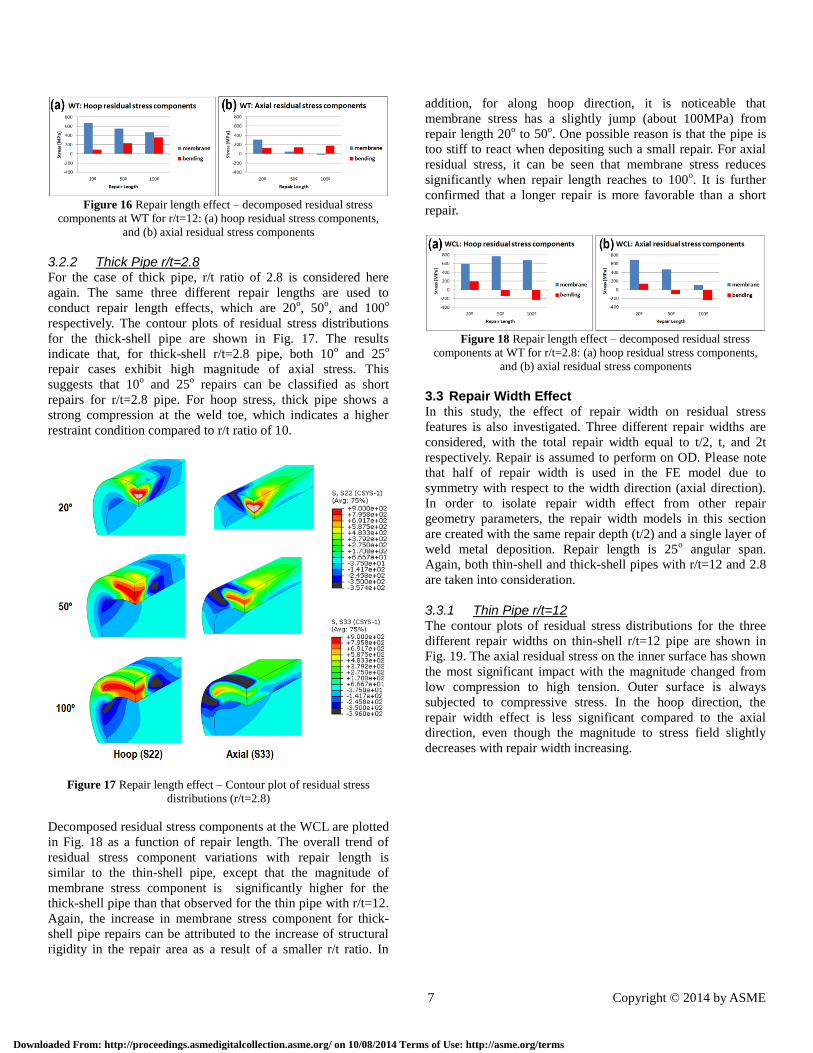
Figure 16 Repair length effect – decomposed residual stress
components at WT for r/t=12: (a) hoop residual stress components,
and (b) axial residual stress components
3.2.2 Thick Pipe r/t=2.8 For the case of thick pipe, r/t ratio of 2.8 is considered here
again. The same three different repair lengths are used to
conduct repair length effects, which are 20o, 50
o, and 100
o
respectively. The contour plots of residual stress distributions
for the thick-shell pipe are shown in Fig. 17. The results
indicate that, for thick-shell r/t=2.8 pipe, both 10o and 25
o
repair cases exhibit high magnitude of axial stress. This
suggests that 10o and 25
o repairs can be classified as short
repairs for r/t=2.8 pipe. For hoop stress, thick pipe shows a
strong compression at the weld toe, which indicates a higher
restraint condition compared to r/t ratio of 10.
Figure 17 Repair length effect – Contour plot of residual stress
distributions (r/t=2.8)
Decomposed residual stress components at the WCL are plotted
in Fig. 18 as a function of repair length. The overall trend of
residual stress component variations with repair length is
similar to the thin-shell pipe, except that the magnitude of
membrane stress component is significantly higher for the
thick-shell pipe than that observed for the thin pipe with r/t=12.
Again, the increase in membrane stress component for thick-
shell pipe repairs can be attributed to the increase of structural
rigidity in the repair area as a result of a smaller r/t ratio. In
addition, for along hoop direction, it is noticeable that
membrane stress has a slightly jump (about 100MPa) from
repair length 20o to 50
o. One possible reason is that the pipe is
too stiff to react when depositing such a small repair. For axial
residual stress, it can be seen that membrane stress reduces
significantly when repair length reaches to 100o. It is further
confirmed that a longer repair is more favorable than a short
repair.
Figure 18 Repair length effect – decomposed residual stress
components at WT for r/t=2.8: (a) hoop residual stress components,
and (b) axial residual stress components
3.3 Repair Width Effect In this study, the effect of repair width on residual stress
features is also investigated. Three different repair widths are
considered, with the total repair width equal to t/2, t, and 2t
respectively. Repair is assumed to perform on OD. Please note
that half of repair width is used in the FE model due to
symmetry with respect to the width direction (axial direction).
In order to isolate repair width effect from other repair
geometry parameters, the repair width models in this section
are created with the same repair depth (t/2) and a single layer of
weld metal deposition. Repair length is 25o angular span.
Again, both thin-shell and thick-shell pipes with r/t=12 and 2.8
are taken into consideration.
3.3.1 Thin Pipe r/t=12 The contour plots of residual stress distributions for the three
different repair widths on thin-shell r/t=12 pipe are shown in
Fig. 19. The axial residual stress on the inner surface has shown
the most significant impact with the magnitude changed from
low compression to high tension. Outer surface is always
subjected to compressive stress. In the hoop direction, the
repair width effect is less significant compared to the axial
direction, even though the magnitude to stress field slightly
decreases with repair width increasing.
Downloaded From: http://proceedings.asmedigitalcollection.asme.org/ on 10/08/2014 Terms of Use: http://asme.org/terms

8 Copyright © 2014 by ASME
Figure 19 Repair width effect – Contour plot of residual stress
distributions (r/t=2.8)
Fig. 20 and 21 exhibit the detailed line plots of through-
thickness residual stress distributions along WCL and WT,
respectively. Horizontal axis is from ID. As can be seen for
axial and hoop residual stresses, with increasing repair width,
stress values of the first half thickness (0-10mm) increase while
the stress values of the second half thickness (10-20mm)
roughly maintain the same. This is similar to the repair depth
effect. It is noticeable that for a narrow repair (2/t), axial
residual stresses are compressive on ID. This is primarily due to
the face that less total heat input to the structure than a wider
repair. The compressive stress on ID is good news from
Fitness-for-Service point of view. As a result, a narrower repair
should be preferred than a wider repair as far as residual stress
is concerned.
Figure 20 Repair width effect – through-thickness residual stress
distributions at WCL for r/t=12: (a) hoop residual stress distributions,
and (b) axial residual stress distributions
Figure 21 Repair width effect – through-thickness residual stress
distributions at WT for r/t=12: (a) hoop residual stress distributions,
and (b) axial residual stress distributions
Through-thickness residual stresses depicted in Fig. 20 and 21
are then decomposed into membrane and bending stresses
according to Eq. (1) as shown in Fig. 22 and 23, respectively. In
general, membrane stress and the absolute value of bending
stress slightly increase as repair width increases. For the wide
repair case, the bending stress is more dominant in the axial
direction at both weld centerline and weld toe locations. Please
note that a negative bending stress in the diagram does not
mean a smaller value. It means a tension on the inner surface
and compression on the outer surface as the line plots shown in
Fig. 13b and 14b. The axial membrane stress is negligible
compared to its bending component. In the hoop direction, the
membrane stress component is dominant in the hoop direction
for all three repair widths. Hoop bending stress is also increased
as the repair width is increased, but to a less degree than the
axial bending stress. So again, it is evident that a narrower
repair is much more desirable than a wider repair.
Figure 22 Repair width effect – decomposed residual stress
components at WCL for r/t=12: (a) hoop residual stress components,
and (b) axial residual stress components
Figure 23 Repair width effect – decomposed residual stress
components at WT for r/t=12: (a) hoop residual stress components,
and (b) axial residual stress components
3.3.2 Thick Pipe r/t=2.8 If r/t ratio of 2.8 is considered, a similar observation to that for
r/t of 12 can be made from Fig. 24 where decomposed residual
stress components at the WCL are summarized. As the repair
width is increased, the axial membrane stress is increased and
axial bending stress is changed from a tension on the outer
surface to a tension on the inner surface. It is not surprising to
see that the axial membrane stresses are much larger than the
ones in thin pipe due to an increased radial stiffness in thick
pipe while hoop membrane and bending stresses relatively
insensitive to repair width.
Downloaded From: http://proceedings.asmedigitalcollection.asme.org/ on 10/08/2014 Terms of Use: http://asme.org/terms
9 Copyright © 2014 by ASME
Figure 24 Repair width effect – decomposed residual stress
components at WCL for r/t=2.8: (a) hoop residual stress components,
and (b) axial residual stress components
4. CONCLUDING REMARKS In this paper, detailed parametric analyses are presented on
effects of repair weld geometry (depth, length, and width) and
component geometry (wall thickness and pipe to thickness
ratio) on resulting residual stress distributions. The results
clearly show repair weld geometry parameters are very
important to the control of residual stresses for fracture
mechanics based fitness for service assessment purpose. The
most desirable repair weld should be as long, as narrow, and as
shallow as practically possible for residual stress control
purpose. These geometric attributes may be referred to as
general rules for achieving an effective residual stress
mitigation by design.
ACKNOWLEDGMENTS The work reported here was supported by the National
Research Foundation of Korea (NRF) Gant funded by the
Korea government (MEST) through GCRC-SOP at University
of New Orleans under Project 2-1: Reliability and Strength
Assessment of Core Parts and Material System. The authors are
grateful to the encouragement and oversight of Project PI
Professor M. H. Kim during the course of this investigation.
REFERENCES [1] Dunn J, MacGuigan J, McLean RJ, Miles L, Stevens RS.
Investigation and repair of a leak at a high temperature
stainless steel butt weld. Proceedings of the international
conference on integrity of high temperature welds 1998;
241-258
[2] The Battelle integrity of nuclear piping (BINP) program
final report – Appendix G: Evaluation of reactor pressure
vessel (BPV) nozzle to hog-leg piping bimetallic weld joint
integrity for the VC summer nuclear power plant report
2005
[3] Gandy DW, Findlan SJ, Viswanathan R. Weld repair of
steam turbine casing s and piping – an industry survey. J
Strain Ana 2000; 35(4):287-305
[4] API Recommended Practice 579 RP. 2nd
Edition. American
Petroleum Institute 2007.
[5] BS 7910:2005, Guide to Methods for Assessing the
Acceptability of Flaws in Metallic Structures. British
Standards Institution 2005.
[6] Procedure R6 Revision 4, Assessment of the integrity of
structures containing defects 2013
[7] Dong P. Length scale in secondary stresses in fracture and
fatigue. Int. J. of Pressure Vessel and Fatigue 2008;
85:124-143
[8] Bouchard PJ. Validated Residual Stress Profiles for
Fracture Assessments of Stainless Steel Pipe Girth Welds.
International Journal of Pressure Vessels and Piping 2007;
84: 195-222
[9] Dong P, Zhang J and Song S., 2013 “Assessment of some
existing residual stress prescriptions for fitness for service
assessment of girth welds”, under review
[10] Dong P, Zhang J, Bouchard PJ. Effects of repair weld
length on residual stress distribution. Transactions of the
ASME 2002; 124:74-80
[11] Dong P, Hong JK, Bouchard PJ. Analysis of residual
stresses at weld repairs. Int. J. of Pressure Vessel and
Piping 2005; 82: 258-269
[12] Dong P, Cao Z, Hong JK. Final PVRC Residual Stress and
Local PWHT JIP Report on Investigation of Weld Residual
Stresses and Local Post Weld Heat Treatment 2005
[13] Elcoate CD, Dennis RJ, Bouchard PJ, Smith MC. Three
dimensional multi-pass repair weld simulations. Int. J. of
Pressure Vessel and Fatigue 2005; 82:244-257
[14] Keppas K, Wimpory RC, Katsareas DE, Anifantis NK,
Youtsos AG. Evaluation of residual stress assessment
methods using a repair weld benchmark. J. Strain Analysis
2010;45:197-208
[15] Brust FW, Scott PM, Yang Y. Weld residual stresses and
crack growth in bimetallic pipe welds. Proceeding of IIW
Conference, 2003
[16] Zeinoddini M, Arnavaz S, Zandi AP, Alizadeh Vaghasloo
Y. Repair welding influence on offshore pipelines residual
stress fields: an experimental study. Journal of
Constructional Steel Research 2013; 86:31-41
[17] Bouchard PJ, George D, Santisteban JR, Bruno G, Dutta M,
Edwards L, Kingston E, Smith DJ. Measurement of the
residual stress in a stainless steel pipe girth weld
containing long and short repairs. Int. J. of Pressure Vessel
and Fatigue 2005; 82:299-310
[18] ABAQUS version 6.11, 2012
[19] Dong P, Hong JK. Recommendations on Residual Stresses
Estimate for Fitness-for-Service Assessment. WRC
Bulletin 2003, No. 476, Welding Research Council, New
York
[20] Brust FW, Dong P, Zhang J. A Constitute for Welding
Process Simulation Using Finite Element Methods.
Advances in Computational Engineering Science 1997,
Proceedings of ICES Conference, pp. 51-56
[21] Dong P. 2001. Residual Stress Analysis of a Multi-Pass
Girth Weld: 3-D Special Shell Versus Axisymmetric
Models. Journal of Pressure Vessel Technology 2001;
123:207-213.
[22] Song S, Dong P and Zhang J., 2012 “A Full Residual
Stress Estimation Scheme for Pipe Girth Welds”,
Proceeding of ASME PVP Conference, Toronto, Ontario,
Canada, July 15-19, 2012
[23] Zhang J, Song S and Dong P, 2011 “Important Residual
stress Features in Reactor Nozzle Dissimilar Metal Welds”,
In: Proceeding of ASME PVP 2011 Conference,
Baltimore, Maryland, July 17-21, 2011. ASME, CD
Publication, ISBN 978-0-7918-4456-4; 2011.
Downloaded From: http://proceedings.asmedigitalcollection.asme.org/ on 10/08/2014 Terms of Use: http://asme.org/termsView publication statsView publication stats