Residential Electrical System Aging Research...
71
Residential Electrical System Aging Research Project Technical Report July 1, 2008 Prepared by: David A. Dini, P.E. Underwriters Laboratories Inc. © 2008 The Fire Protection Research Foundation
Transcript of Residential Electrical System Aging Research...

Residential Electrical System Aging Research Project
Technical Report
July 1, 2008
Prepared by: David A. Dini, P.E.
Underwriters Laboratories Inc.
© 2008 The Fire Protection Research Foundation

PREFACE
In 2002, in response to questions regarding the influence of aging and installation quality on the fire safety of electrical systems, the Fire Protection Research Foundation initiated a collaborative research and development project designed to address the issue through a comprehensive survey of the condition of representative samples of residential electrical components installed in different eras and U.S. locations. A total of 30 homes were harvested from across the U.S. ranging in age from 30 to 110 years. This report presents a summary of the results of this study. Lessons learned have included the potential impact of original installation quality and inspection as additional factors to be considered in performance. It is hoped that this project will provide critical information to code writers – especially for NFPA 73 and the NEC® – as well as AHJs, electrical equipment manufacturers, installers, property owners, and insurers.

Technical Advisory Committee Members And Principal Sponsors
Jack Wells, Chair
Michael O’Boyle
American Lighting Association
Cooper Industries
Doug Geralde CSA Group
David Brender
Copper Development Association
Kevin Lippert Eaton Corporation
John Goodsell
Hubbell Wiring Systems
Steve Campolo Leviton Manufacturing Co., Inc.
Mark Earley
National Fire Protection Association
Ralph Baldwin Pass & Seymour/Legrand Company
David Mercier
Southwire Company
John Machnicki John Sleights
St. Paul Travelers
Jack Jordan State Farm Insurance Companies
David Dini
Underwriters Laboratories Inc.

Douglas Lee
Andrew Trotta U.S. Consumer Product Safety Commission
U.S. Fire Administration (through CPSC)
Donald Cook (liaison)
Shelby County (AL) Dept. of Development Services

With special appreciation to the following individuals who coordinated the
harvesting of electrical wiring and devices from the older houses
Merton Bunker, Stafford, VA
Andy Cartal, Yardley, PA
Donny Cook, Pelham, AL
Art Cote, Marshfield, MA
Paul Dobrowsky, Rochester, NY
Jim Imlah, Hillsboro, OR
Bill McGovern, Plano, TX
Bob Meier, Grafton, WI
John Sleights, Windsor, CT
Steve Wydeveld, Homer Glen, IL
The Committee would also like to thank the following people who assisted with the actual harvesting and/or helped with other aspects of this project:
Tarry Baker, Doug Boyd, Deanna Cook, Stephen Cook, Reginald Coutant, Paul Courtney, Fred Crosby, David Dubiel, Dave Hill, Kurt Ingram, Bob Johnston, Joey Johnston, Wil Johnston, Jerry Maicach, Bob McCullough, Chris McGoldrick, Lanny McMahill, Nelson Montgomery, Dennis Muilenberg, John Muncy, Tim Owens, Ed Palka, Keith Phillips, Dave Pope, Gary Wilson, and Bob Worthey.
The Committee acknowledges a special thanks to the Birmingham Electrical JATC for help with the harvesting at several of the houses.

Residential Electrical System
Aging Research Project
Technical Report
July 1, 2008
Prepared by: David A. Dini, P.E.
Underwriters Laboratories, Inc.
Prepared for: The Fire Protection Research Foundation
1 Batterymarch Park Quincy, MA 02169-7471

ii
Foreword
According to the National Fire Protection Association (NFPA), there is an annual average of 24,200 home fires attributed to electrical distribution systems or lighting equipment, causing 830 injuries, 320 deaths and $700 million in property damage.1 A study conducted by the U.S. Consumer Product Safety Commission (CPSC) in 1987 indicated that the frequency of fires in residential electrical systems was disproportionately high in homes more than 40 years old.2 The disproportionately high incidence of fire in the electrical systems of older homes can usually be attributed to one or more of the following factors:3
• Inadequate and overburdened electrical systems. • Thermally reinsulated walls and ceilings burying wiring. • Defeated or compromised overcurrent protection. • Misuse of extension cords and makeshift circuit extensions. • Worn-out wiring devices not being replaced. • Poorly done electrical repairs. • Socioeconomic considerations resulting in unsafe installations.
Although residential electrification first began in the later part of the 19th century in the more wealthy homes, by the beginning of the 20th century, electricity in the home was becoming available and more affordable to many people, especially those living in the urban areas. With over 100 years of residential electrification in many cities and towns, the aging of the residential electrical infrastructure is beginning to raise concerns within the electrical and firefighting communities. Besides the natural effects that age can have on wire insulation and electrical equipment over time, residential electrical systems are seldom inspected after their original installation. In addition, the quality of the original installation may be a factor, as well as inappropriate upgrades or additions that may have been done by unqualified homeowners or others throughout the years. This report describes a research project to characterize the condition of various age groups of residential electrical components by surveying, recovering, and analyzing representative samples of actual installed residential wiring systems, wiring devices, and similar distribution and utilization equipment. The data and analysis of this equipment is intended to provide critical information to code writers, especially for NFPA 73 Electrical Inspection Code for Existing Dwellings, and the National Electrical Code® (NEC®), as well as AHJs, electrical equipment manufacturers, testing laboratories, installers, property owners, and insurers.
1 NFPA Fire Analysis & Research Division, private communication, February 2008. 2 D. McCoskrie, L. Smith. “What Causes Wiring Fires in Residences?” Fire Journal, Jan-Feb 1990. 3 Technology for Detecting and Monitoring Conditions That Could Cause Electrical Wiring System Fires. Prepared for U.S. Consumer Product Safety Commission by Underwriters Laboratories Inc., Contract No. CPSC-C-94-1112, September 1995.

iii
TABLE OF CONTENTS
Introduction 1.0 Background
1.1 Initial Plan and Objectives 1.2 Revised Plans
2.0 Houses Obtained 2.1 Test and Analysis of Recovered Devices 3.0 Wire and Cable Systems 3.1 Knob and Tube Wiring 3.1.1 Findings 3.2 Armored Cable 3.2.1 Findings 3.3 Nonmetallic-Sheathed Cable 3.3.1 Findings 3.4 Conductor Insulation 3.4.1 Findings 4.0 Service 4.1 Findings 5.0 Overcurrent Protection Devices 5.1 Fuses 5.1.1 Findings 5.2 Circuit Breakers 5.2.1 Findings 6.0 Grounding and Bonding 6.1 Circuit Grounding 6.1.1 Findings 6.2 Equipment Grounding 6.2.1 Findings 7.0 Receptacle Outlets 7.1 Findings 8.0 Luminaires 8.1 Findings 9.0 Wire Splices and Junction or Outlet Boxes 9.1 Findings 10.0 Ground-Fault Circuit Interrupters 10.1 Findings

iv
TABLE OF CONTENTS (Continued) 11.0 Code Violations 11.1 Findings 12.0 Summary of Findings 12.1 Effects of Aging 12.2 Misuse and Abuse 12.3 Non-Code Compliant Installations APPENDIX (on CD) Detailed reports on the testing and analysis of the recovered wiring and devices from each of the houses that are included in this study

1
INTRODUCTION
On December 31, 1879, Thomas Edison exhibited his newly invented electric lighting in a few houses along a residential neighborhood in Menlo Park, New Jersey. That New Year’s Eve night proved to be not only historical in terms of its significance to American ingenuity and invention, but it also signified the beginnings of residential electrification in the United States. By the turn of the century, electricity in the home was becoming available to more and more people. By 1920, just 40 years after Edison first introduced residential electric lighting, half the urban and rural non-farm homes in the U.S. had electrical service, and by 1940, that number would increase to 90%.4 The Rural Electrification Act of 1935 further extended the reaches of electric service to those living in even remote farm areas. Since the earliest civilizations, no single technology has likely influenced the family home more than electricity. Electricity has been a permanent fixture in most residential occupancies for over 100 years. It is estimated that over 30 million homes, or about one-third of the U.S. housing stock, is over 50 years old. Although many of these homes have had their electrical service or wiring upgraded or expanded over the years, many also have not. Since 1897, the National Electrical Code (NEC) has been used by professional installers and others to provide the practical safeguarding of persons and property from hazards arising from the use of electricity. However, many municipalities and jurisdictional authorities, especially in the more rural areas, did not begin adopting the NEC and applying inspection practices until well after the use of electricity in the home had become popular. In addition to the intentional or unintentional use of unsafe wiring practices throughout the years, the safety of electrical systems can be compromised because of the effects of aging. The earliest residential wiring systems were open conductors with rubber insulation. By the 1920s, these were being replaced with cables having cloth jackets or steel armor encasing the rubber insulated conductors. Then, as modern thermoplastics became more available, the wire insulations and jacket materials soon changed to plastic. Overcurrent protection to protect these wires against fire began as a simple fusible cutout, which soon developed into the replaceable plug fuse. By mid-century circuit breakers began protecting these wires, and eventually more modern arc-fault circuit interrupters. In the early days, receptacle outlets in the home were few and far between, as not many home appliances were yet available or even envisioned. As technology brought more and more appliances and electronic equipment into the home, both the homeowner and the NEC demanded the convenience and safety of having more receptacles throughout the house. By the 1970s, modern electronics even allowed for the ground-fault circuit interrupter, and the protection against electric shock in the home, in addition to fire. 4 U.S. Bureau of the Census. The statistical history of the United States, from colonial times to the present. New York: Basic Books, 1976.

2
Although residential electrical wiring practices have changed throughout the years, it is relatively unknown what effect age may be having on these older wiring systems and electrical devices. Also, some homeowners, especially those who may not have the financial means or resources to upgrade their electrical systems, may be reverting to unsafe wiring practices to accommodate a home with more modern appliances and electronic equipment than it was originally intended for decades ago. To this end, the Fire Protection Research Foundation (FPRF), in conjunction with the U.S. Consumer Product Safety Commission (CPSC), and various electrical equipment manufacturers, insurance companies, testing laboratories, and other interested parties, established the Residential Electrical System Aging Research Project. The goal of this project was to characterize the condition of various age groups of residential electrical systems, by surveying a representative sampling of actual installed systems from homes across the country, and then documenting how aging and installation may relate to residential electrical fire causes.

3
1.0 Background A study conducted by the CPSC back in the 1980s indicated that the frequency of fires in residential electrical systems was disproportionately high in homes more than 40 years old. Although several factors could be attributed to this high incidence of fire in the electrical systems of older homes, the aging of older electrical systems, combined with the fact that older homes were not built to the more rigid building codes of recent times, probably were the most contributing factors. Recognizing the need to more fully study the effects that age may have on residential electrical systems and fires, the CPSC approached the Fire Protection Research Foundation in the early 2000s about such a project. In 2003, FPRF formed a Technical Advisory Committee (TAC) of interested parties, including government, industry, insurance, and testing laboratories, to oversee the project and provide principal sponsorship. After several initial meetings, it was decided that the project needed a way to characterize the condition of various age groups of residential electrical system components by surveying, recovering, and analyzing representative samples of actual installed wiring systems, wiring devices, and similar distribution and utilization equipment from older homes. One means of accomplishing this was to identify homes that were ready for demolition, and then attempt to get permission from the building’s owner to access the building. Once access is gained, volunteers could then survey and photo document the electrical system, and then harvest selected wiring system components and electrical devices for further study in the laboratory. To achieve a good cross-section of data, homes from different decades (e.g. 1910s, 1920s, 1930s, etc.), up to about 1970 would need to be found. Homes would also be selected from various parts of the country, as climatic and other regional conditions could affect aging. Recognizing the need for professionally trained volunteers from across the country to help coordinate these efforts, several jurisdictional authorities (electrical inspectors) were asked to participate in the project. In late 2003, the first pilot project study was conducted with a house in the Chicago, Illinois area. In 2004, a few more pilot projects were conducted in Alabama, and with this practical experience, a systematic process with a detailed plan and instructions for the surveying of the house and harvesting of the components was developed. The goal of the project was to survey and harvest from about 100 homes from eight different regions of the country over a two-year period. However, after beginning in 2005 and concluding in 2007, about 30 houses were harvested. Difficulties in finding enough homes suitable for the project, as well as organizing enough volunteers to do the surveying and harvesting work, made the initial goal of 100 houses a challenge. However, the work that was accomplished from just 30 houses, and the data that was obtained, was deemed to be significant.

4
Initial Plan and Objectives
The initial plan was to survey and harvest from older houses in eight different states; New Jersey, Florida, Alabama, Wisconsin, Illinois, Arizona, California, and Oregon. After volunteers were identified and solicited to help in these parts of the country, a detailed plan, with instructions and data sheets, was developed for them to use in the recovery process. The objective was for these volunteers, who were primarily electrical inspectors, to use contacts through their local building departments or inspector and contractor associations, to identify residential occupancies that would no longer be used for habitat and were scheduled for demolition or otherwise rendered to a state of non-use. After securing the building owner’s permission, the plan was to organize a small group of additional volunteers who would help in the surveying and photo documenting of the building’s electrical system, and then identify and harvest selected electrical wiring and device components for recovery and shipment back to the UL laboratories for further analysis. For documentation and control purposes, each house was assigned a unique identifier consisting of the state abbreviation in which the property was located, followed by a sequential state number, e.g. “IL-1”. The initial survey of the house asked for information about the building including its location, age, style, and architecture. In addition, the descriptions of any additions or modifications that may have been made to the house, including upgrades to the electrical system, were made where possible. The identifying of past building permits, or talking to the building owner, often helped in this regard. Also documented was the nature and extent of the building’s thermal insulation, and the grounding electrode system. Next, the building was photographed from the outside, including electrical features, and a sketch of the building and the rooms within, including the approximate size of each, was made. This sketch would also be used later to identify the specific location of the devices selected for recovery. Labels, consisting of masking tape, were then prepared for the devices that would be recovered. Each room was assigned a code, such as LR for living room, DIN for dining room, KIT for kitchen, etc. Components were also assigned a code, such as R1, R2 for receptacles, LUM1, LUM2 for luminaires, etc. For example, a device labeled “KIT-R1” would be kitchen receptacle No. 1. For each room or area of the house, the number of outlet receptacles, wall switches, and types of luminaires was documented. Each receptacle was tested for its plug blade retention force using a receptacle tension tester. Any problems relating to poor or unqualified workmanship, damage to devices, lack of Code compliance, and/or other hazards such as overlamping, permanent use of extension cords, etc., was documented and photographed. Representative photographs from various rooms were taken to help identify and document the

5
general layout and structure of the house. The electrical devices, and their respective label, were also photographed for later use. The initial plan was to conduct an electrical survey of the house while it was still energized, but that did not prove to be feasible. Once the surveying and photo documenting was completed, the following components of the electrical system, where possible, were harvested:
• A sample of the utility service drop and the service entrance cable. • The service entrance panel and 3 ft of each branch circuit wiring attached
to the panel. Overcurrent devices and any subpanels were also recovered. • Receptacles from the kitchen, bathrooms, laundry areas, outdoors, those
dedicated to major appliances, and all GFCIs. The recovery tried to encompass the outlet box (without disturbing any wiring), faceplate, and 3 ft of wire on each side. If it was deemed safe to do so, the wall stud was removed with the outlet box attached. Any other receptacles in the house that looked suspect because of damage, overheating, or a low plug blade retention force were also recovered.
• Luminaires from the kitchen, outdoors, and any that extended into the attic space. The installed lamps were also recovered. The recovery tried to encompass the outlet box (without disturbing any wiring) and 3 ft of wire.
• Examples of the building’s wiring system(s) from the attic area and the basement or crawl space areas were recovered. About 20 ft cut into 5 ft lengths were obtained. If more than one wiring system (armored cable, NM, etc.) was found, or different ages of wiring systems were found, as evidenced by rubber versus plastic insulation, examples of these were recovered also.
• A few junction boxes, especially where splices were encountered, including 3 ft of wire coming from the box, were recovered. Also recovered were any improper splices, including splices that were not made in appropriate boxes.
• Other devices such as the meter socket, wall switches, fans, etc. were recovered if they showed evidence of problems such as overheating, arcing, water damage, corrosion, etc. Any devices that appeared to be very old or unusual were also recovered.
• If any cord sets (extension cords) were still found in the house, they were recovered and labeled as to where they were found.
Once the harvesting was completed, the recovered wiring and devices were boxed and shipped to the UL laboratories where they would be subjected to testing and further analysis.

6
Revised Plans As the project proceeded, several obstacles were encountered that jeopardized the finding of 100 houses from across the country, and meeting of the initial plan objectives for the harvesting and recovery of the electrical devices. These included:
• Many houses that were scheduled for demolition were torn-down very soon after the permit was obtained. Quickly organizing a crew of volunteers became difficult.
• Some building owners did not want to incur the liability of having outsiders enter a house ready for demolition.
• Some localities were experiencing more or fewer teardowns than others because of economic or other conditions.
• Although some supplies were provided to the volunteers, such as a camera, measurement instruments, labeling products, etc., larger equipment such as power tools, ladders, electric generators, etc., had to be found by the local volunteers.
• Some municipalities would not permit their employees to participate in the project during normal working hours.
• Houses ready for demolition can be the subject of vandalism, especially with regards to the electrical wire and devices with copper.
To adjust for these unexpected obstacles, revised plans were developed mid-way into the project in an attempt to secure some additional houses in a limited fashion, while still maintaining the important data and recovery devices. Reduced harvesting procedures were developed that focused on surveying only the basic information about the house, and any unsafe wiring practices or devices. The recovery efforts concentrated on examples of the building’s wiring system(s), service entrance panel and overcurrent devices, one or two receptacles and luminaires from key rooms such as the kitchen, bath, and outdoor areas, and other devices that showed damage or misuse. Efforts were also made to work with remodelers who were removing electrical wiring and devices from a house that was being remodeled, but not completely torn-down. In some cases, only the devices could be recovered, without benefit of the outlet box and/or wall stud. Contacts within the fire service community were pursued, as they often have access to older houses for fire training purposes. New participants from other regions and cities were identified and solicited to help facilitate the harvesting of these additional houses from parts of the country that were not originally anticipated.

7
2.0 Houses Obtained As a result of the initial and revised plans and efforts, data and recovered devices were obtained from 30 houses in 10 different states. These included; Alabama (9 houses), Connecticut (1 house), Illinois (6 houses), Massachusetts (3 houses), New Jersey (1 house), New York (2 houses), Oregon (2 houses), Texas (2 houses), Virginia (3 houses), and Wisconsin (1 house). The following is a brief description of each house. House AL-1 was an 1100 ft2 wood frame ranch house in the Birmingham, Alabama area that was built in 1960. It had a 100 Amp service and used NM cable for the branch circuits throughout the house. House AL-2 was a 1500 ft2 wood frame ranch house in the Birmingham, Alabama area that was built in 1920. It had a 150 Amp service and used NM cable for the branch circuits, but there were some older original circuits that used open knob and tube type wire. House AL-3 was a 1500 ft2 brick style ranch house in the Birmingham, Alabama area that was built in 1962. It had a 60 Amp service and used NM cable for the branch circuits throughout the house. House AL-4 was a 1200 ft2 wood frame ranch house in the Birmingham, Alabama area that was built in 1953. The rating of the service could not be determined, but appeared to have been updated sometime after 2000, and used NM cable for the branch circuits throughout the house. House AL-5 was a 1200 ft2 wood frame ranch house in the Birmingham, Alabama area that was built in 1927. The rating of the service could not be determined, but NM cable was used for the branch circuits throughout the house. House AL-6 was a 1600 ft2 wood frame split-level house in the Birmingham, Alabama area that was built in 1976. It had a 200 Amp service and used NM cable for the branch circuits throughout the house. House AL-7 was a 1350 ft2 wood frame ranch house in the Birmingham, Alabama area that was built in 1959. The rating of the service could not be determined, but NM cable was used for the branch circuits throughout the house. House AL-8 was a mid-sized wood frame house in the Birmingham, Alabama area that was built in 1959, but renovated in 1980. It had a 200 Amp service and used NM cable for the branch circuits throughout the house. House AL-9 was a smaller wood frame ranch house in the Birmingham, Alabama area that was built in 1915. It had a 150 Amp service and used NM cable for the branch circuits throughout the house.

8
House CT-1 was located in the Hartford, Connecticut area and was built in 1962. It had a 200 Amp service that was upgraded in the 1990s, and AC and NM cable was used for the branch circuits throughout the house. The house kitchen was being remodeled, and the old wiring and electrical devices that were removed for the remodel were given to the project. House IL-1 was a 1700 ft2 two-story brick house in the Chicago, Illinois area that was built in 1928. It had a 100 Amp service and used AC cable for the original branch circuits, but some newer circuits used individual conductors in metallic tubing. House IL-2 was a 1000 ft2 brick ranch house in the Chicago, Illinois area that was built in 1924. It had a 100 Amp service that was upgraded in the 1970s, and used AC cable for the original branch circuits, but some newer circuits used individual conductors in metallic tubing. House IL-3 was an 800 ft2 wood frame ranch house in the Chicago, Illinois area that was built in 1940. The rating of the service could not be determined, but AC cable was used for the branch circuits throughout the house. House IL-4 was an 800 ft2 brick ranch house in the Chicago, Illinois area that was built in 1961. It had a 100 Amp service and used a mixture of AC cable and individual conductors in metallic tubing for the branch circuits throughout the house. House IL-5 was a smaller wood frame ranch house in the Chicago, Illinois area that was built in 1958. It had a 125 Amp service and used a mixture of AC cable and individual conductors in metallic tubing for the branch circuits throughout the house. House IL-6 was a 1400 ft2 two-story wood frame house in the Chicago, Illinois area that was built about 1910. The rating of the service could not be determined, but the original wiring system in the house was open type knob and tube wire, with NM and AC cable added later for the branch circuits throughout the house. House MA-1 was a mid-sized two-story wood frame lake house in the Boston, Massachusetts area that was built in the 1920s. The rating of the service could not be determined, but AC cable was used for the original branch circuits, and NM cable was added later when converted to a year-around house. House MA-2 was a wood Victorian house in the Boston, Massachusetts area that was built in 1897. The rating of the service could not be determined, but open type knob and tube wire was used for the original branch circuits, and NM and AC cable was added later. The house was being remodeled, and the old wiring and electrical devices that were removed for the remodel were given to the project.

9
House MA-3 was a 1000 ft2 two-story wood frame ocean front house in the Boston, Massachusetts area that was built about 1910. The rating of the service could not be determined, but NM cable was used for the branch circuits throughout the house. House NY-1 was a larger two-story wood frame house in the Rochester, New York area that was built about 1870, but probably not wired for electricity until the early 20th century. It had a 100 Amp service and used AC cable and NM cable for the branch circuits throughout the house. House NY-2 was a larger two-story wood frame house in the Rochester, New York area that was built about 1910. It had a 200 Amp service, and the electrical wiring was newer that was probably part of renovations in the 1980s. Individual conductors in nonmetallic tubing, along with some NM cable, were used for the branch circuits throughout the house. House NJ-1 was built around 1960 in the Princeton, New Jersey area, and was a recent service upgrade. The rating of the service was 150 Amps. Only the service panel and overcurrent devices were recovered. House OR-1 was a 2000 ft2 two-story wood frame house in the Portland, Oregon area that was built about 1910. It had a 40 Amp service, and the original wiring system in the house was open type knob and tube wire, with NM and some AC cable added later for the branch circuits throughout the house. House OR-2 was a 1000 ft2 wood frame ranch house in the Portland, Oregon area that was built in 1954. It had a 200 Amp service that was upgraded in 1987, and used NM cable for the branch circuits throughout the house. House TX-1 was a smaller wood frame ranch house in the Dallas, Texas area that was built in 1950. It had a 60 Amp service and used NM cable for the branch circuits throughout the house. House TX-2 was a smaller house in the Austin, Texas area that was built about 1930. The rating of the service could not be determined, but open type knob and tube wire was used for the branch circuits throughout the house. The house was being remodeled, and some of the old wiring and electrical devices that were removed for the remodel were given to the project. House VA-1 was a 1200 ft2 wood frame ranch house in the Washington DC / Virginia area that was built in 1981. It had a 200 Amp service and used NM cable for the branch circuits throughout the house.

10
House VA-2 was a 950 ft2 wood frame manufactured house in the Washington DC / Virginia area that was manufactured in 1972, and located at the permanent site in 1980. It had a 200 Amp service and used NM cable for the branch circuits throughout the house. House VA-3 was a 1000 ft2 wood frame ranch house in the Washington DC / Virginia area that was built in 1975. It had a 200 Amp service and used NM cable for the branch circuits throughout the house. House WI-1 was a 1300 ft2 1-1/2 story wood frame house in the Milwaukee, Wisconsin area that was built in 1962, but portions may have been older. It had a 60 Amp service and used AC cable and some NM cable for the branch circuits throughout the house.
2.1 Test and Analysis of Recovered Devices
All of the recovered wiring and electrical devices were sent to the UL laboratories in Northbrook, Illinois for further testing and analysis. In many cases, original product standard tests such as temperature rise, dielectric withstand, and overcurrent device calibration were conducted on the aged equipment in the laboratory while the device was still mounted and wired as though it were in its original setting in the house. In addition to the testing, the recovered devices were analyzed for characteristics such as damage, overheating, misuse, non-code compliance, and poor workmanship. A detailed report was written for each house. The report included a description of the house, representative photographs of the house and the recovered devices, and the results of the testing and analysis. All of the individual house reports can be found in a separate appendix.

11
3.0 Wire and Cable Systems
3.1 Knob and Tube Wiring The earliest residential wiring systems were an open wiring system often referred to as “knob-and-tube.” The individual conductors were run spaced apart at least 2-1/2 inches (if exposed), but as the wires passed through walls and floors, they could be susceptible to dampness and abrasion, which could eventually lead to leakage currents and arcing fires. For protection in these places, “insulating tubes” which could be placed in wood holes were used. These tubes were made of porcelain, with a flange on one end and set on an angle to prevent the tube from sliding through the hole. To support the individual conductors in other places, a wide variety of insulators, including porcelain knobs and cleats were used. These were nailed to the wood structure, and included a leather washer under the nail head to prevent the porcelain from being cracked when it was hammered in place. Although knobs had two grooves, they could not be used to support two wires of opposite polarity. However, cleats could be used when wires were run in parallel. In addition to keeping the wires spaced apart, these knobs and cleats also helped in keeping the conductors away from wood and other damp surfaces, as well as providing a degree of strain relief. Where free ends of wire attached to boxes, fixtures, and other devices, a special water resistant cotton braid tubing known as “loom” was used to cover the wire. Knob-and-tube wiring systems began being phased out in the 1930s, probably because of the then growing popularity of nonmetallic and armored cable systems for residential buildings. For new installations, the NEC has not permitted knob-and-tube wiring since the mid-1970s, however, it is still described in the NEC for existing installations and by special permission.
Fig. 1a – Knob-and-Tube Wiring From House IL-6

12
Fig. 1b – Knob-and-Tube Wiring From House IL-6
3.1.1 Findings
Five houses still employed a knob-and-tube wiring system for at least some of the circuits in the house. To determine the dielectric properties of the recovered knob-and-tube wire, a two-foot length of the wire was used for test purposes. The dielectric potential was applied between the conductor and a one-foot piece of aluminum foil that was tightly wrapped around the approximate center of the wire length. The dielectric potential was raised from 0 to 5000 Volts at a rate of 500 Volts per second, and then maintained at 5000 Volts for one minute. A sample of wire from house AL-2 failed the dielectric test at 1500 Volts, a sample of wire from house TX-2 failed the dielectric test at 3200 Volts, and a sample of wire from house OR-1 failed the dielectric test at 3500 Volts. All of the other samples of wire that were tested passed the dielectric test without breakdown at 5000 Volts or less.
Fig. 2 – Knob-and-Tube Wiring From House OR-1

13
3.2 Armored Cable Armored cable (AC) was first listed in 1899 for the Sprague Electric Co. of New York, and was originally called “Greenfield Flexible Steel-Armored Conductors,” after one of its inventors, Harry Greenfield. There were originally two experimental versions of this product, one called “AX” and the other “BX,” with the “X” standing for “experimental.” The “BX” version became the one that eventually got produced, and hence the name “BX” stuck, which also became the registered trade name of armored cable for General Electric, who later acquired Sprague Electric. Armored Cable first appeared in the 1903 NEC, but didn’t become popular until around 1930, and is still a popular wiring method today. The armor of AC cable systems is tested for grounding and can provide a suitable equipment grounding path. AC cable made after 1959 requires a No. 16 AWG aluminum bonding strip under the armor to help improve the conductivity of this path.
Fig 3 – Old Armored Cable Being Removed From House IL-1
3.2.1 Findings
Armored cable was found in 12 of the houses. To determine the dielectric properties of the recovered armored cable, two approximate two-foot lengths of the cable were used for test purposes. With one sample, the dielectric potential was applied between each conductor (line-to-line). With the other sample, the dielectric potential was applied between the conductors and the metal armor (ground). For each sample, the dielectric potential was raised from 0 to 5000 Volts at a rate of 500 Volts per second, and then maintained at 5000 Volts for one minute. All of the AC cable samples that were tested from all of the houses passed the dielectric test line-to-line and line-to-ground without breakdown at 5000 Volts or less.

14
A resistance measurement of the finished armor, including the bonding conductor, was made on representative samples of each of the recovered armored cable systems as follows. The resistance of the armor was determined by placing a sample of the cable on a nonconductive surface. The sample was as long as possible, but typically not longer than 5 ft. The ends of the armor were cleaned by wire brushing the armor to remove any surface coatings or corrosion. The ends were then secured firmly into wire connectors. The leads of a double-bridge ohmmeter were connected to the wire connectors, and the resistance of the armor was measured directly in Ohms. The resistance in Ohms per 100 ft was calculated as follows:
Ohms per 100 ft = (Ohms (measured) / Length (feet armor)) X 100 All of the recovered AC cable samples incorporated steel armor, and had two conductors per cable, except for two that had three conductors and one that had four. The UL4 Standard for Armored Cable includes a resistance of armor measurement on new cable similar to that described above, but with a 10 foot sample. The following are the maximum acceptable values of armor resistance in Ohms per 100 feet. Prior to 1959, the standard permitted higher values of resistance, as the aluminum bonding strip was not required. However, there were some cables that were manufactured before 1959 that also incorporated a bonding strip. For example, MA-1 Sample 1, WI-1 Sample 1, and NY-1 Sample 2 had an aluminum bonding strip that was approximately No, 18 AWG. NY-1 Sample 1 had a copper bonding strip that was approximately No. 20 AWG. Another sample, IL-1 Sample 3, had an aluminum bonding strip that was No. 16 AWG, but the sample appeared to be much older than 1959.
Max acceptable resistance Ohms per 100 feet AWG size of conductors (1) (2)
14 0.75 1.50 12 0.64 1.12 10 0.56 0.90
(1) – With bonding strip and made after 1959 (2) – Made before 1959 (with or without bonding strip)
Table I summarizes the resistance of armor measurements on the recovered samples of AC cable.

15
Table I – Armored Cable Resistance Measurements
* - three conductor cable ** - four conductor cable
Fig 4 – AC Cable From Basement of House IL-1 With Some Corrosion
House Sample Recovered Wire Size Measured Max PermittedID No. From (AWG) yes/no AWG size Ohms/100 ft Ohms/100 ft
CT-1 1 kitchen 12 yes 16 1.45 0.64CT-1 2 kitchen 14 yes 16 0.78 0.75IL-1 1 bedroom 14 no 2.36 1.50IL-1 2 attic 14 no 2.68 1.50IL-1 3 basement 12 yes 16 0.91 0.64IL-2 1 attic 14 no 3.02 1.50IL-2 2 bedroom 14 no 3.23 1.50IL-3 1 dining room 14 no 2.50 1.50IL-3 3 bathroom 14 yes 16 0.90 0.75IL-4 1 laundry room 14 yes 16 0.74 0.75IL-4 2 garage 14 yes 16 0.72 0.75IL-5 1 basement 14 yes 16 0.68 0.75IL-5 2 basement 12 yes 16 0.51 0.64IL-6 1 kitchen 12 yes 16 0.65 0.64IL-6 2 basement 10* yes 16 0.31 0.56
MA-1 1 kitchen 12** yes 18 2.15 0.64MA-1 2 living room 14 no 3.53 1.50MA-2 1 unknown 14 no 3.22 1.50NY-1 1 basement 14 yes 20 CU 1.67 1.50NY-1 2 basement 12* yes 18 0.93 1.12OR-1 1 unknown 12 no 3.05 1.12WI-1 1 attic 14 yes 18 0.79 0.75WI-1 2 bedroom 14 no 2.07 1.50
Bonding Strip

16
Table II shows the armor resistance measurements for the 2-conductor cables that were tested, both No. 14 and 12 AWG, with and without a No. 16 AWG aluminum bonding strip.
Table II – Armored Cable Measurement Comparisons
For the 2-conductor No. 14 AWG cable, the average resistance of the five cables with the bonding strip was 0.76 Ohms/100 ft, and for the eight cables without the bonding strip the average resistance of the eight cables was 2.83 Ohms/100 ft. For the 2-conductor No. 12 AWG cable, the average resistance of the four cables with the bonding strip was 0.88 Ohms/100 ft, and for the one cable without the bonding strip the resistance was 3.05 Ohms/100 ft.
House Sample Recovered Wire Size Measured Max PermittedID No. From (AWG) yes/no AWG size Ohms/100 ft Ohms/100 ft
CT-1 2 kitchen 14 yes 16 0.78 0.75IL-3 3 bathroom 14 yes 16 0.90 0.75IL-4 1 laundry room 14 yes 16 0.74 0.75IL-4 2 garage 14 yes 16 0.72 0.75IL-5 1 basement 14 yes 16 0.68 0.75
IL-1 1 bedroom 14 no 2.36 1.50IL-1 2 attic 14 no 2.68 1.50IL-2 1 attic 14 no 3.02 1.50IL-2 2 bedroom 14 no 3.23 1.50IL-3 1 dining room 14 no 2.50 1.50
MA-1 2 living room 14 no 3.53 1.50MA-2 1 unknown 14 no 3.22 1.50WI-1 2 bedroom 14 no 2.07 1.50
IL-1 3 basement 12 yes 16 0.91 0.64IL-5 2 basement 12 yes 16 0.51 0.64IL-6 1 kitchen 12 yes 16 0.65 0.64CT-1 1 kitchen 12 yes 16 1.45 0.64
OR-1 1 unknown 12 no 3.05 1.122-conductor No. 12 AWG cable without bonding strip
Bonding Strip
2-conductor No. 14 AWG cable with bonding strip
2-conductor No. 14 AWG cable without bonding strip
2-conductor No. 12 AWG cable with bonding strip

17
3.3 Nonmetallic-Sheathed Cable
Although nonmetallic-sheathed cable, or NM for short, was first listed and described in the NEC in 1926, it was actually invented a few years earlier by General Cable at their Rome Wire Division in Rome, NY, and marketed under the trade name “Romex®.”5 Early NM cable had their individual conductors jacket wrapped in a cotton braid that was impregnated with either a varnish or tar-like substance for moisture protection. Around 1950, synthetic spun rayon was being permitted to replace the cotton thread in the jacket braid. Then in the early 1960s, thermoplastic (PVC) began replacing the braided jacket altogether, and by about 1970, most all NM cable had a plastic PVC outer jacket, even though a braid was still permitted until 1984. Also in 1984, NM-B cable was developed and required to have 90°C rated individual conductors, and a 75°C outer jacket. Until the early 1960s, most NM cable for residential use did not have a grounding conductor. However, changes in the 1962 NEC that mandated equipment grounding for all branch circuits popularized the use of NM cable with ground.
Fig. 5 – Old NM Cable From House AL-3 With Damaged Jacket
5 Today the Romex brand name belongs to the Southwire Company.

18
3.3.1 Findings
Most of the houses from this project used nonmetallic cable to some extent, except for the houses from the Chicago, Illinois area, where the use of nonmetallic cable has long been prohibited by most local Codes. To determine the dielectric properties of the recovered nonmetallic cable, two approximate two-foot lengths of the cable were used for test purposes. With one sample, the dielectric potential was applied between each conductor (line-to-line). With the other sample, the dielectric potential was applied between the conductors and a one-foot piece of aluminum foil that was tightly wrapped around the approximate center of the cable jacket. For nonmetallic cables with a grounding conductor, the foil and the grounding conductor were connected. For each sample, the dielectric potential was raised from 0 to 5000 Volts at a rate of 500 Volts per second, and then maintained at 5000 Volts for one minute. All of the NM cable samples that were tested from all of the houses passed the dielectric test line-to-line and line-to-ground without breakdown at 5000 Volts or less.
Fig. 6 – NM Cables From House VA-3

19
3.4 Conductor Insulation
Original knob-and-tube wire and older AC or NM wiring systems used conductor insulation made of gum-rubber. This “rubber” insulation was actually a mixture of ingredients including vulcanizing agents containing sulfur for curing. These various additives, especially sulfur, had a very corrosive effect on the copper conductor, so the copper had to be tinned. Rubber was also very soft when first vulcanized, so a cotton braid or wrap was added as an outer covering for mechanical protection. During the 1950s, the wire industry began transitioning residential wire insulation from rubber to the newly developed thermoplastics, such as PVC. PVC had advantages in that it did not suffer from the brittleness and cracking with age that was typical of the older rubber insulation. It also did not have sulfur additives that could damage the conductor, so the copper did not have to be tin-coated. Another advantage of PVC was that there were more options with color pigmentations, and the color tended to hold its pigmentation better than rubber, which often had a painted wrap that discolored with time.
3.4.1 Findings To further investigate comparisons between the older thermoset rubber and more recent thermoplastic wire insulation materials, a special study was conducted by UL to measure certain electrical, mechanical, combustibility, and chemical composition characteristics of wire and cable conductor insulation that was recovered from the older homes. This study was conducted in mid-2006, and only included samples from houses that were harvested from up until that time. Also included in this study were some additional wire samples that were obtained from insurance investigations, and some samples that were obtained from the initial pilot projects. The individual conductors were either knob-and-tube wire, conductors installed in metal tubing, or taken from AC or NM cables. The results of this study were included in a published paper titled, An Analytical Study of Some Physical Properties of Wire and Cable Samples Collected from Older Homes.6 The paper contained the following conclusions:
Many houses built over the last 100 years continue to operate with an electrical system infrastructure that may have been original to the building, or at least significantly older than the more modern appliances and furnishings used within the home.
6 D. A. Dini, T. Z. Fabian, J. T. Chapin, “An Analytical Study of Some Physical Properties of Wire and Cable Samples Collected from Older Homes,” The Fire Protection Research Foundation Aged Electrical Systems Research Application Symposium, Chicago, Illinois, October 18-19, 2006, pp. 28-48.

20
Rubber insulated wires, typical of the 1950s vintage and earlier, can still perform well in many residential environments and expected use conditions. Care, however, should be taken to adequately inspect these older wiring systems for damage, especially where subjected to bending, abrasion, or harsh usage over the years. Thermoplastic insulated wires, typical of the 1950s vintage and later, generally continue to perform with excellent results, even after 50 years or more of service in the home. The electrical and mechanical characteristics of these wires appear to be exceeding even the original expectations of performance after aging and normal use. Wire and cable systems that have been improperly installed, such as those intended for indoor use only, but installed outdoors, can show signs of aging and deterioration well beyond what should be expected.
Figures 1 and 2 from that study showed the results of the dielectric and dielectric / bend tests respectively when plotted versus age of the wire. Both rubber and thermoplastic insulated wires were compared. For the dielectric test, the middle one-foot of the wire was wrapped tightly in aluminum foil. The dielectric test voltage was applied between the conductor and the aluminum foil. The voltage (ac) was first increased from zero to 5 kV at a rate of 500 Volts per minute, and then held constant for one minute. If no breakdown occurred, the voltage was then increased from zero to 20 kV at a rate of 500 Volts per minute. If dielectric breakdown occurred at less than 20 kV, the potential at dielectric breakdown was noted. For the dielectric / bend test, two feet of unaltered wire was used. For this test, the wire was bent around a mandrel of small diameter (e.g. 0.313 inch for No. 14 AWG, and 0.375 inch for No. 12 AWG). Each specimen was tightly wound for six complete turns onto the mandrel. The sample was then immersed in steel shot and subjected to a dielectric test similar to that described above, between the conductor and the steel shoot, up to 20 kV. The trends clearly showed a reduction in dielectric strength and bend strength with age; however, this may have been largely due to the inherent property characteristic differences between older rubber insulations and newer thermoplastic insulations. In general, thermoplastic insulations performed very well with age. Figures 1 and 2 from that study are shown here for reference.

21
Fig. 2 - Dielectric/Bend Test Results vs Age
0
5
10
15
20
0 10 20 30 40 50 60 70 80 90
Approximate Age (yrs)
Ben
d / D
iele
ctric
Bre
akdo
wn
(kV
)
Rubber
Thermoplastic
Fig. 1 - Dielectric Test Results vs Age
0
5
10
15
20
0 10 20 30 40 50 60 70 80 90
Approximate Age (yrs)
Die
lect
ric B
reak
dow
n (k
V)
Rubber
Thermoplastic

22
Fig. 7 – Brittle Conductor Rubber Insulation From House AL-7
Fig. 8 – Brittle Knob-and-Tube Wire From House TX-2

23
4.0 Service A residential electrical service typically consists of service entrance conductors that connect to the electric utility at a point of common coupling near the house. These service conductors first terminate at a meter socket where the utility’s electric meter is located. Either integral to the meter socket, or often not far from it, is the service panel where the main disconnect for the service, and the overcurrent devices for the feeder and branch circuits are located. The rating of the electrical service is typically 100 to 200 Amps, but can be higher in larger houses that demand more loads, or even smaller in older houses that have not been upgraded to adequately accommodate the more modern use of appliances. The earliest main disconnect switches were of a blade type typically rated 30, 60 or 100 A. When a cut-out or fuse opened, power to all or most of the house was lost. It soon became popular to add several circuits or “branch circuits,” each protected by an individual fuse. Often times these additional fuses were located in a separate box called the “fuse cabinet.” By the 1930s, the fusible pull-out switch was becoming a popular form of service equipment for new housing. This switch incorporated two main cartridge fuses in a single base that could be pulled out for fuse replacement, or inverted and reinserted in an “off” position when used as a disconnect. A second fusible pull-out switch was often incorporated and marked “range.” This fused circuit was typically used to provide power for the growing use of residential electric range cooking. This range circuit could either be in series or in parallel with the main fuses. The lighting and appliance branch circuits were fed through plug fuses and fuseholders that were integral to the box. In the 1930s, the first “no-fuze (sic) load center” was introduced. Instead of fuses, this new load center used residential circuit breakers for the main and branch circuit overcurrent protection. Literature at that time touted the no-fuze load center as a great convenience because fuses were seldom on hand when they were needed the most. The early no-fuze load centers were relatively expensive for the time, and all but the very expensive houses were still being built with fuses for overcurrent protection. It wasn’t until the early 1950s, and the post-war housing boom, that low cost residential circuit breakers and load centers were becoming available, and by the 1960s the circuit breaker had almost completely replaced fuses as the choice for overcurrent protection in new construction housing.
4.1 Findings With most of the houses surveyed, one or more of the following common problems were found at the service entrance:

24
• Service entrance panels used outdoors that were not suitable for outdoor use, or had been improperly installed or damaged to the extent that water could enter the enclosure.
• Corrosion, vegetation growth, and/or insect infestation found inside the box.
• Unused open knock-outs. Cable clamps either not used, or very loose. • Ratings, markings, or important information missing, painted over, or not
legible. • Evidence of arcing from a conductor, splice, or terminal to the enclosure.
Evidence of arcing at a circuit breaker stab where it connects to the panel bus.
• Circuit breakers installed that were not of a manufacturer or type marked suitable for use in the panel.
• The neutral bus either not properly bonded to ground with a main bonding jumper, or the neutral being additionally bonded to ground at a second location, such as at a subpanel.
• Branch circuit conductors or feeders not being protected by the proper size overcurrent protection device. A penny being used to defeat a blown plug fuse.
• Wiring terminals incorporating more than one wire when not marked suitable for such use, or multiple grounded conductors in a single terminal.
• White colored conductors connected to circuit breakers and used as ungrounded conductors, without being reidentified for such use. Neutral conductors that had black colored insulation.
Each service panel was subjected to a dielectric test at 1500 Volts for one minute between live parts of opposite polarity and between live parts and ground. None of the service panels experienced any dielectric breakdown as a result of this test.
Fig. 9 – Arcing at Conductor Splice at House WI-1

25
Fig. 10 – Meter Socket With Corrosion From House NY-1
Fig. 11 – Arcing Damage at Breaker Stab at House MA-3

26
5.0 Overcurrent Protection Devices
5.1 Fuses The earliest form of overcurrent protection was referred to as a “fusible cut-out.” The fusible cut-out consisted of a block or box of porcelain arranged so that a piece of easily fusible material, called the “fuse,” would form part of the electrical circuit. When the current in the circuit became too great, the fuse would melt and “cut-out” the load to that circuit. By 1900, the term fusible cut-out was becoming known as a fuse-block or fuseholder. To make the replacement of the fusible material easier, the safety plug fuse was developed in the 1890s to be easily replaced by simply screwing a new fuse into the fuseholder once it had blown. Because of the popularity of the Edison-base screw shell, all plug fuses soon standardized on this thread arrangement. Plug fuses are interchangeable with fuses of different current ratings up to 30 Amps, and thus a higher current rated fuse could inappropriately be placed in a circuit rated for smaller ampacity. However, plug fuses rated 15 A or less had to be identified by a hexagonal cap or other prominent top part to distinguish them from fuses of higher ampere ratings, and this is still a requirement in the NEC
today. The Edison base design also makes it easy to use a penny to bridge a plug fuse. This, very dangerous practice was sometimes done by homeowners to by-pass a blown fuse when a new one was not available. The 1940 NEC contained a new requirement which stated that for new installations, plug fuseholders must only accept a “Type S” tamper resistant plug fuse. In addition to not being usable in a standard Edison-base fuseholder, the Type S fuse had to be designed such that fuses rated 16 – 30 A could not be used in a fuseholder intended for fuses rated 0 – 15 A. The product requirements for Type S fuses eventually incorporated three non-interchangeable current ranges, 0 – 15, 16 – 20, and 21 – 30 A. The tamper-resistant plug fuse was also of a design that would not allow a penny to bridge the fuse when installed.
5.1.1 Findings Plug fuses were found in eight (8) of the houses. Some of these were older houses that had not been upgraded to load centers with circuit breakers, or older houses that did have a service upgrade with circuit breakers, but retained the older fuse panel as a subpanel for the older branch circuits. In other cases plug fuses were used in fusible switches for devices such as water heaters or water pumps.

27
In total, 44 plug fuses were recovered. No Type S fuses or Type S fuse adapters were found, including in houses that were built after 1941. The breakdown of the plug fuses by ampere rating were as follows:
With most houses, the fuses rated greater than 20 Amps were protecting wires sized 12 or 14 AWG. Most of the fuses rated 20 Amps were protecting 14 AWG size wires. Only in house AL-5 were 30 Amp fuses found actually protecting No. 10 AWG size copper wires. All of the recovered fuses, both plug and cartridge type, were subjected to a calibration test as follows. The fuse was installed in a separate fuseholder of the correct type and size. The terminals of the fuseholder were connected to a variable low voltage source using appropriately sized copper wire. The calibration test was conducted at 200% of rated current. With an ammeter in the circuit, and the voltage adjusted to produce the appropriate test current, a timer was used to record the length of time needed for the fuse to open while carrying the test current. The following test currents and maximum allowable opening times were applied as taken from the UL248 Standards for Low Voltage Fuses: All of the recovered fuses calibrated properly within the allowable time at the required test current.
Rating Test Allowable(Amps) Amps Minutes
15 30 420 40 430 60 440 80 650 100 660 120 670 140 8
100 200 8
200% Calibration
HouseID 15 A 20 A 25 A 30 A
AL-1 1 1 6AL-3 4AL-5 1 3AL-8 2 8AL-9 5IL-4 2NY-1 1 2WI-1 1 1 6
Totals 2 6 2 34
Number of Plug Fuses Found

28
Fig. 12 – 30 Amp Fuses From House AL-8
Fig. 13 – Penny Found Behind Blown Fuse at House AL-9

29
5.2 Circuit Breakers
Most of the houses surveyed used circuit breakers for protection of the branch circuits. Although fuses were used as the original overcurrent devices for most houses built before the 1950s, and even though circuit breakers did not become predominate until the 1960s, many of the older houses that predated the 1960s had been upgraded to circuit breaker protection.
5.2.1 Findings In total, 421 circuit breaker poles were recovered from the houses. These included main breakers rated up to 200 Amps, as well as a variety of feeder and branch circuit breakers in the range of 15 – 100 Amps, both one and two pole. Each circuit breaker was subjected to a calibration test as follows. Except where not possible, the circuit breakers were calibrated in the panelboards in which they were found, and with the breaker handle in the un-operated “on” position when found in that state. For branch circuit breakers, the line side connection to a low voltage source of supply was made to the panel’s main bus bar, either through the main breaker’s line side or other suitable means. The other side of the current source was connected to the load terminal wire of the breaker under test, without disturbing or retightening the terminal. The calibration test was conducted at 300% of rated current. With an ammeter in the circuit, and the current source adjusted to the appropriate test current, a timer was used to record the length of time needed for the circuit breaker to trip while carrying the test current. The following test currents and maximum allowable trip times were applied as taken from NEMA Standards Publication AB-4-2003. With some of the earlier houses, the calibration test was conducted at 200% of rated current, with allowable trip times taken from the UL489 Standard for Molded-Case Circuit Breakers.
Rating Test Allowable Test Allowable(Amps) Amps Min:Sec Amps Min:Sec
15 45 0:50 30 2:0020 60 0:50 40 2:0030 90 0:50 60 2:0040 120 1:20 80 4:0050 150 1:20 100 4:0060 180 2:20 120 6:0070 210 2:20 140 6:00100 300 2:20 200 6:00125 375 3:20 250 8:00150 450 3:20 300 8:00200 600 3:50 400 10:00225 675 3:50 450 10:00
300% Calibration 200% Calibration

30
Although circuit breakers of the 15- or 20-ampere size are permitted to trip within one or two minutes at 300% or 200% of rated current, most tripped within 10 or 20 seconds. Of the 421 circuit breaker poles tested, five (5) did not calibrate properly, as indicated by a failure to trip or the inability to open all poles when it did trip. Table III below describes those circuit breakers.
Table III – Circuit Breakers That Did Not Calibrate Properly
All five of the circuit breakers were found installed in a combination meter socket / panelboard enclosure located outdoors. In most all cases, the enclosure had some aspect to the installation that compromised the integrity of the enclosure to properly protect the installed devices from the weather and other outdoor elements. All of the circuit breakers had at least one pole that would not open with 300% rated current. Each circuit breaker was disassembled and analyzed for the possible cause of the calibration failure. Circuit breaker AL-4, 18B, was additionally examined by manufacturer A. The examination concluded the following:
“No major issues were found with the components of the breaker except some overheating of the braid (discoloration) and adjacent discoloration and blistering of the base molding. (Note that this could have been from the repeated testing done at UL) Some oxidation of plated parts internally and externally were the norm. During 200% testing the pole would not trip within 3 minutes at which time the breaker was turned off to prevent damage to the pole. “The cover was removed and the latch load was checked. The load should have been between 3-7 ounces. The actual readings were between 11 and 15 ounces. This increase was attributed to surface corrosion as the latch load decreased after the pole was tripped and relatched several times. “The latch bite between the cradle and the armature latch was noted as being very deep but the breaker was retested once again at 200%. Again, the breaker did not trip in 3 minutes.
House Breaker AmpID ID Rating Poles Mfgr.
AL-4 18B 40 2 AAL-8 9-11 60 2 BAL-8 2-4 40 2 BAL-9 1-3 30 2 BAL-9 5-7 30 2 B

31
“Based on the above assessment it appeared the thermal calibration may be too high on this pole. A shim (.027 thick) was placed between the cradle and armature to provide the proper latch engagement for this amperage and the breaker was retested once again at 200% and it tripped in 53 seconds. It appears that this breaker pole may not have been properly calibrated initially.”
The other four circuit breakers, which were all made by manufacturer B, were examined by UL. A visual inspection of the opened molded cases identified extensive corrosion on many of the operating mechanism and spring parts. Remnants of insect infestation were also noticeable. Circuit breaker AL-9, 1-3, had the stationary and moveable contacts of one pole permanently welded together. All of the other breaker poles had contacts that would separate. Other than circuit breaker AL-9, 1-3, no definitive determination could be made as to the probable cause of the initial calibration failures.
Fig. 14 – Service Enclosure From House AL-8

32
Fig. 15 –House AL-8 Breaker 9-11, Corrosion Damage
Fig. 16 –House AL-9 Breaker 5-7, Insect Nesting
Fig. 17 –House AL-9 Breaker 1-3, Welded Contact

33
6.0 Grounding and Bonding
6.1 Circuit Grounding Circuit grounding was one of the more hotly contested topics in the early history of electrification. In the early 1890s, the New York Board of Fire Underwriters had condemned the practice of grounding the neutral as a dangerous practice, especially in the typical residential 3-wire Edison 120/240 Volt system. The Edison utility companies, on the other hand, found just cause to ground their supply systems, even as others thought the utilities were doing this to just save copper and money at the cost of an increased fire risk. The great debate continued for over a decade, but in 1903 the NEC was revised to recommend that these circuits be grounded, and finally in the 1913 NEC a mandatory circuit grounding requirement was included for circuits like the popular 120/240 Volt system. The most common way to ground a residential wiring system has always been to use the building’s metal water piping as a grounding electrode. The early Codes permitted water-piping systems of 3-Ohms or less to ground to be used as an electrode, which was usually the case if the metal water pipe extended several feet into the ground. In 1923, the NEC first mentioned electrodes of driven rod or pipe. The 1925 NEC further referred to these driven electrodes as “artificial” electrodes, and required them to be at least 8 feet long, with minimum diameters of ½ inch for a rod and ¾ inch for pipe. It also noted that if only one of these artificial electrodes had a resistance of greater than 25 Ohms to ground, then two artificial electrodes had to be provided spaced at least 6 feet apart. In 1951, the NEC was revised to indicate that if there was 10 feet or less of metal water pipe in contact with the earth, or if there was the likelihood of the metal water piping system being disconnected, then the grounding system needed to be supplemented with an additional electrode. Ten years later, in 1971, the NEC
further strengthened that requirement by stating that a water pipe electrode must always be supplemented with an additional electrode, which in most cases meant adding a rod or pipe electrode to the house’s grounding system. In 1999, the NEC was again revised to require this water pipe supplemental rod or pipe electrode to have a resistance to ground of 25 Ohms or less, or be augmented by an additional electrode. Also in recognition of the increased use of non-metallic water pipe, the NEC Code was revised to state that interior water pipe more than 5 feet from the entrance to the building shall not be used as part of the grounding electrode system.

34
6.1.1 Findings
When conducting the initial survey of the house, an attempt was made to describe and document the building’s grounding electrode system. However, no attempt was made to exhume ground rods or measure the resistance to ground. In most cases, a properly sized grounding electrode conductor was found at the service entrance, however, in several cases there was either a poor or loose connection at the service or the electrode itself. House IL-2 had no grounding electrode conductor connection to the water piping system, only to a pipe electrode. With house AL-1, a satellite TV dish system on the house was grounded to an 18-inch spike that was not bonded to the building’s grounding electrode system. In some houses, such as VA-1 and VA-3, the neutral bus was not bonded to the enclosure (ground) at the service, as no main bonding jumper was used. In other houses, especially where there had been a service upgrade and the original service panel now became a subpanel, the subpanel still had its neutral bus bonded to ground.
6.2 Equipment Grounding Homes built before the 1960s had most of their original 125 V receptacle outlets of the non-grounding 2-prong type. In 1947, the NEC first required grounding type (3-prong) receptacles for the laundry. In 1956, the required use of grounding type receptacles was extended to basements, garages, outdoors and other areas where a person might be standing on ground. Finally, in 1962 the NEC was revised to require all branch circuits to include a grounding conductor or ground path to which the grounding contacts of the receptacle must be connected. That effectively discontinued the use of non-grounding type receptacles except for replacement use in existing installations were a grounding means might not exist.
6.2.1 Findings Several houses were found that had branch circuit wiring systems with NM cable without ground, as they were originally built before the 1960s. However, many of these houses also had receptacles of the 3-prong grounding type, without any equipment grounding conductor connection to the receptacle’s grounding contact.

35
7.0 Receptacle Outlets
In the early days of residential electrification, it is believed that many utilities charged by the total number of outlets in the home, including all the receptacle outlets, rather than the actual energy used. Reference to the number of receptacle outlets in family dwellings first appeared in the 1933 NEC. It recommended, but did not require, for all single family dwellings of more than 400 square feet that in every kitchen, dining room, breakfast room, living room, parlor, library, den, sun room, recreation room and bed room, where any outlet is installed in such room, a sufficient number of receptacle outlets to be installed to provide that no point on the wall, as measured horizontally on the wall, will be more than 15 feet distant from such outlet. In 1935, the 15-foot distance remained as a recommendation only, but a requirement was added to indicate that at least one receptacle outlet must be installed in each room. Two years later, in 1937, the “15 foot” recommendation was changed to “10 feet,” and the recommendation became a requirement. In 1940, the requirement was changed to state that one outlet shall be provided for every 20 linear feet of distance around the room as measured horizontally along the wall at the floor line. And then in 1956, the “20 linear feet” measurement was changed to “12 linear feet.” And finally in the 1959 NEC, the first use of the present language is found that requires receptacles to be installed so that no point measured horizontally along the floor line in any wall space is more than 6 feet from a receptacle outlet.
7.1 Findings In many of the older houses, additional receptacle outlets were added over the years to accommodate newer devices such as window air conditioners, or the multitude of appliances used on kitchen countertops. Some homes, such as AL-1, were found with additional receptacles added by simply running flexible cord along the wall from a previous outlet. House IL-3 had a garage receptacle made with a permanently connected extension cord. House IL-4 had an extension cord permanently used in a bathroom that was not even protected by a GFCI. House OR-1 had a three-outlet receptacle tap hanging from a bedroom ceiling by unsecured NM cable. Several examples of flexible cord used in place of fixed wiring were found in House WI-1. Each recovery team was provided with a receptacle tension tester, Woodhead Model 1760, and asked to check each receptacle in the house. If any receptacle had a retention force measurement that was very low, such as less than 5 ounces, it was recovered. Any receptacles that showed evidence of damage, overheating, or arcing were also recovered. This was in addition to recovering several representative receptacles from key rooms or areas such as the kitchen, bathrooms, laundry area, outdoors, those dedicated to major appliances, and all GFCIs.

36
Once back in the laboratory, each receptacle was inspected for the manufacturer’s name, ampere (plug) rating, if of the grounding type, the size and type of the attached branch circuit wire and the minimum single blade retention force. The minimum back-off torque on the wiring terminals was also measure, however, this was not conducted until after the temperature testing. The temperature test was conducted with each receptacle mounted and installed in the as-received condition, which usually included the original outlet box and portion of the wall stud to which it was attached. With a shorting plug installed in one receptacle position, the temperature test was conducted for 10 minutes at 15 amps. The test was also repeated on the other outlet position of the duplex receptacles. The temperature rise at each blade was measured at the blade/receptacle interface. If a temperature rise exceeded 20° C, the test was repeated after inserting and withdrawing a clean blade 10 times. The blade was made clean by wiping it with isopropyl alcohol after each insertion. If a temperature rise still exceeded 20° C, the test was repeated with the wiring terminals tightened to 9 in-lb. The basic temperature test requirement from the UL498 Standard for Attachment Plugs and Receptacles for a 15-ampere receptacle is a maximum temperature rise of 30° C with 15 amps of continuous current. Initial work with this project showed that if the receptacle temperature rise did not exceed a 20° C rise after 10 minutes at 15 amps, its continuous temperature rise would not likely exceed 30° C. Therefore, this test was conducted for only 10 minutes to conserve time. The inserting and withdrawing a clean blade 10 times was an attempt to remove any corrosion or surface contaminates that may have deposited on the contacts of the receptacle from long-term non-use. The 9 in-lb tightening torque was to represent the standard test tightening torque used on a receptacle terminal with 14 or 12 AWG wire. The receptacles were also subjected to a dielectric withstand test of 1250 V for one minute between live parts of opposite polarity, and between live parts and ground after the temperature test. All samples tested passed the dielectric test. In all, 254 receptacles were tested. They ranged in age from the 1920s and possibly even earlier, to more modern receptacles that may have been recently replaced by the homeowner. Also noted for each receptacle was an age factor. Age factor 1 was a grounding type receptacle that appeared to be made from the mid-1960s or later, and probably in service for less than 50 years. Age factor 2 was a non-grounding type receptacle that appeared to be made and installed between 1930 and the mid-1960s, and probably in service for about 50 - 75 years. Age factor 3 was a receptacle that appeared to be made and installed before 1930, and probably in service for over 75 years.

37
Of the 254 receptacles tested, 55 receptacles passed the initial temperature test with a temperature rise of 20° C or less. Of the remaining 199 receptacles, 133 had a temperature rise of 20° C or less after the ten cleaning insertions, and 30 had a temperature rise of 20° C or less after the retightening of the wire terminal. Some receptacles were wired using push-in terminals or had leads, and could not be tightened. 53 receptacles exceeded a temperature rise of 20° C under any of the test conditions. Table IV summarizes the temperature rise test, including comparisons by age factor.
Table IV – Receptacle Temperature Test Results
Fig. 18 – House IL-1 Receptacle From the 1920s
Receptacle Total After AfterType Quantity Initial Cleaning Tigntening Never
All 254 55 133 30 53Age Factor 1 178 45 95 22 33Age Factor 2 62 8 32 6 16Age Factor 3 14 2 6 3 3
Passed Temperature Test

38
Fig. 19 – House IL-6 Receptacle From the Early 20th Century
To further explore and compare the loose retention force on some of the receptacles, two receptacles from house AL-6, identified as LR-R3 and DR-R1, were disassembled and examined. The receptacles appeared to be original to the house, and about 30 years old. Receptacle LR-R3 had zero retention force at one of the outlet positions. Closer inspection of the contact gaps at this receptacle location showed them to be 0.083 and 0.095 inches wide. Receptacle DR-R1 had greater than 24 ounces retention force at its outlet positions. Closer inspection of the contact gaps at this receptacle location showed them to be 0.043 and 0.049 inches wide. However, not much was known about any use or abuse that these receptacles may have been subjected to while in service.
Fig. 20a – House AL-6, LR-R3 Fig. 20b – House AL-6, DR-R1

39
8.0 Luminaires
8.1 Findings
An attempt was made to recover luminaires from the kitchen, outdoor areas, and any that extended into the attic space; however, in many cases luminaires were also recovered from other areas of the house. The installed lamps were recovered when found. A thorough examination of the luminaire was made in the laboratory. The following possible hazardous conditions with the use of the luminaires were noted. Examples of houses where that conditioned had occurred are noted in parenthesis.
• Overlamping. Typically a 75 W or 100 W lamp was installed in a luminaire that was marked for use with a maximum 60 W lamp (AL-7, IL-1, IL-5, OR-1, WI-1). It was also noticed that many very old luminaires were not marked with any maximum lamp size.
• Marked for use with 90° C supply wires, but 60° C wires used (AL-2, AL-4, AL-7, IL-4, VA-2, WI-1). In house IL-6, a kitchen luminaire was found marked for use with 150° C supply wire.
• Small gauge wire or flexible cord used to splice luminaire to supply wires (AL-1, AL-4, AL-8, MA-1, OR-1, OR-2).
• Frayed or damaged wire insulation (IL-1, WI-1). Ballast leads brittle and frayed (AL-2).
• Outdoor box not properly sealed, corrosion present (VA-1). Corrosion from near-by ocean (MA-3).
• Box not properly grounded (AL-6, VA-1).
Fig. 21 – House AL-2, Ballast Leads Brittle and Conductor Exposed

40
There were also several houses where proper outlet boxes were not used for installing the luminaire. With house AL-6, a recessed ceiling luminaire was located in the shower area. It did not appear to be a complete recessed luminaire fixture, and markings were missing regarding its type, IC or NON-IC. However, there was insulation placed around the fixture and in contact with the metal housing. There was extensive corrosion and evidence of overheating on the painted metal housing and on the wood stud adjacent to the housing. The luminaire wires were brittle and some bare conductor was exposed. There was no junction box and no ground connection to the metal housing. The proper size maximum lamp (60 W) was found installed.
Fig. 22 – Recessed Luminaire From House AL-6
All of the recovered luminaires were subjected to a dielectric withstand test of 1200 V for one minute between live parts and the enclosure. In general, there was no evidence of dielectric breakdown with any of the samples, except in cases where damage to the luminaire may have occurred during shipment. An outdoor luminaire from house AL-7 failed the dielectric test at 1000V. It was rated for use in wet locations, and had a date code of 2003.

41
9.0 Wire Splices and Junction or Outlet Boxes
Most early wire splices were soldered and taped joints. Solder joints are still permitted in the NEC, and require the splice to be mechanically secure without solder (twisted), and then soldered. The joint must then be covered with insulation equivalent to the conductors. Early splice joints were twisted, soldered, wrapped with rubber insulating tape, and then covered with friction tape to prevent abrasion. Friction tape is a cloth tape impregnated with a sticky tar or pitch substance. Friction tape was not known to be an insulating material, but many of the older houses were found with splices improperly wrapped with friction tape alone. Plastic insulating tape, often referred to as vinyl tape, was developed in the 1940s, and by 1960 was replacing rubber tape and the need for friction tape for most common splices. Black became the standard color for vinyl tape because of its resistance to ultraviolet light, but modern vinyl tapes are also available in a wide variety of colors so they can be used not only for insulation purposes, but also for wire identification. The use of the twist-on wire connectors can be found since the early 1920s. The early twist-on connectors were made of porcelain and similar inorganic materials, and did not contain an inner spring. By 1930, plastic Bakelite connectors, an early thermoset plastic material, were beginning to appear, and by the 1940s inner springs were added to better twist and more securely capture the conductors. By the late1960s, thermoplastic (nylon, polypropylene, etc.) twist-on connectors were becoming common, and aluminum wire combinations were added to accommodate the increased use of aluminum wire. Most older houses have metal junction or boxes, however, boxes made of Bakelite were available by the late 1920s. Boxes made of more modern PVC thermoplastic material were not introduced until the late 1960s. Several houses were found that had wire splices that were not contained in junction boxes. Except for older knob-and-tube wiring systems, open type splices were generally not permitted in the NEC.
9.1 Findings The following possible hazardous conditions with the use of wire splices and junction or outlet boxes were noted. Also noted in parenthesis are examples of houses where that conditioned had occurred.
• No junction or outlet box used, and open splices found (AL-5, AL-8, OR-1, OR-2, WI-1).
• No box cover, or cable clamps not used (AL-1, AL-5, IL-3, MA-1, VA-1). • Box not secured to structural surface (AL-1, AL-3, WI-1). • Splices not soldered (AL-8, IL-3, MA-1).

42
Fig. 23 – Junction Box From House OR-1
Fig. 24 – Cable Clamp Not Used At House IL-3

43
10.0 Ground-Fault Circuit-Interrupters
The ground-fault circuit-interrupter (GFCI) was developed in the 1960s based on a concept by Professor Charles Dalziel of the University of California at Berkeley. The NEC first required the GFCI in 1968 for underwater swimming pool lighting fixtures. In subsequent years, the NEC was revised to add the required use of GFCIs to other areas of the house, especially locations where people would be standing on earth or cement ground, or near water. Although early GFCIs were primarily incorporated into circuit breakers, by the 1980s, receptacle type GFCIs were also becoming popular. Statistics prepared by the CPSC and others have shown a significant decrease in the number of accidental electrocutions in the U.S. since the GFCI was first introduced. GFCIs were first required by the NEC at various locations in and around the home as follows:
1968 - Swimming Pool Underwater Lighting 1971 - Receptacles Near Swimming Pools 1973 - Outdoor Receptacles 1975 - Bathroom Receptacles 1978 - Garage Receptacles 1981 - Whirlpools and Tubs 1987 - Receptacles Near Kitchen Sinks 1990 - Receptacles in Unfinished Basements and Crawl Spaces 1993 - Receptacles Near Wet Bar Sinks 1996 - All Kitchen Counter-Top Receptacles 2005 - Receptacles Near Laundry and Utility Sinks
10.1 Findings
Nine of the houses had one or more GFCIs installed. A total of 23 GFCIs were found, 21 were of the receptacle type and two were of the circuit breaker type. All of the GFCIs were tested in the laboratory using the internal GFCI push-test feature, and an external 6 mA GFCI tester. Of the 21 receptacle type GFCIs, four did not test and function properly. One additional GFCI was miswired line-load. Of the two circuit breaker type GFCIs, one did not test and function properly. Table V below summarizes the GFCIs that were found and the results of the testing of each:
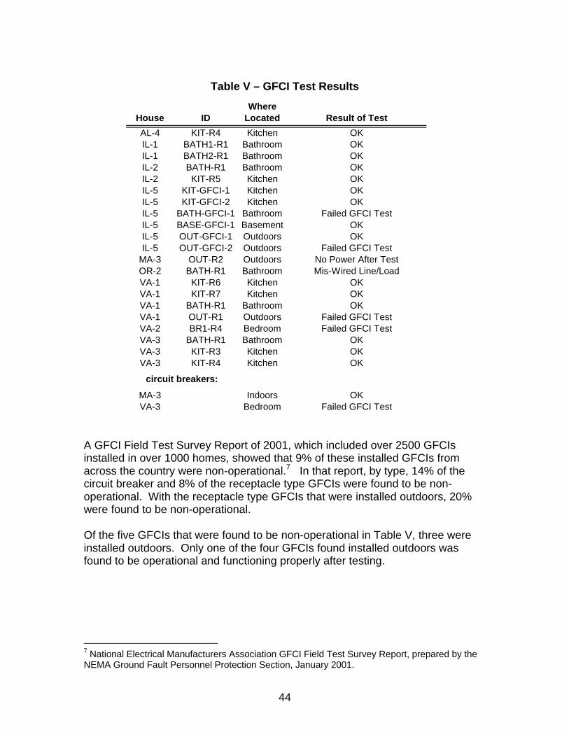
44
Table V – GFCI Test Results
A GFCI Field Test Survey Report of 2001, which included over 2500 GFCIs installed in over 1000 homes, showed that 9% of these installed GFCIs from across the country were non-operational.7 In that report, by type, 14% of the circuit breaker and 8% of the receptacle type GFCIs were found to be non-operational. With the receptacle type GFCIs that were installed outdoors, 20% were found to be non-operational. Of the five GFCIs that were found to be non-operational in Table V, three were installed outdoors. Only one of the four GFCIs found installed outdoors was found to be operational and functioning properly after testing.
7 National Electrical Manufacturers Association GFCI Field Test Survey Report, prepared by the NEMA Ground Fault Personnel Protection Section, January 2001.
WhereHouse ID Located Result of TestAL-4 KIT-R4 Kitchen OKIL-1 BATH1-R1 Bathroom OKIL-1 BATH2-R1 Bathroom OKIL-2 BATH-R1 Bathroom OKIL-2 KIT-R5 Kitchen OKIL-5 KIT-GFCI-1 Kitchen OKIL-5 KIT-GFCI-2 Kitchen OKIL-5 BATH-GFCI-1 Bathroom Failed GFCI TestIL-5 BASE-GFCI-1 Basement OKIL-5 OUT-GFCI-1 Outdoors OKIL-5 OUT-GFCI-2 Outdoors Failed GFCI Test
MA-3 OUT-R2 Outdoors No Power After TestOR-2 BATH-R1 Bathroom Mis-Wired Line/LoadVA-1 KIT-R6 Kitchen OKVA-1 KIT-R7 Kitchen OKVA-1 BATH-R1 Bathroom OKVA-1 OUT-R1 Outdoors Failed GFCI TestVA-2 BR1-R4 Bedroom Failed GFCI TestVA-3 BATH-R1 Bathroom OKVA-3 KIT-R3 Kitchen OKVA-3 KIT-R4 Kitchen OK
MA-3 Indoors OKVA-3 Bedroom Failed GFCI Test
circuit breakers:

45
Fig. 25a– House IL-5, Non-Operational GFCI Receptacle With No
Outdoor Faceplate or Box Cover
Fig. 25b– House IL-5, Non-Operational GFCI Receptacle With No
Outdoor Faceplate or Box Cover (closer view of Fig. 25a)

46
11.0 Code Violations
Since the late 1890s, the NEC has provided installers with the fundamental principles for the protection of people and property from hazards arising from the use of electricity. Many governmental bodies that legislate legal jurisdiction over electrical installations use this Code for both law and regulatory purposes. Enforcement of the Code has traditionally been the responsibility of the authority having jurisdiction, whose duties can include interpreting rules, permitting alternative methods, and approving equipment and installations. However, many municipalities and jurisdictional authorities, especially in the more rural areas, did not begin adopting the NEC and applying inspection procedures until well after the use of electricity in the home had become popular. Besides the effects that aging can have on electrical equipment, non-Code compliant installations can also have an impact on expected performance and safety. Some unqualified installers, or even “do it yourself” homeowners, may have reverted to unsafe wiring practices to save money or time with an installation or remodel of a home. These non-Code compliant practices can worsen with time, and often are passed on to unsuspecting future owners of the house. The nine houses described in this Report from Alabama were all from Shelby County, a onetime rural area just outside metropolitan Birmingham, but has recently become the fastest growing county in the state. Shelby County did not adopt the NEC and Code enforcement (building permits, etc.) until 1988, although many homes in the county were known to have electricity since the 1920s or earlier. All of the nine Alabama houses were first built before 1988, and many Code violations were evident in them.
11.1 Findings
The NEC is now revised every three years, with the current edition, the 51st, being the 2008. However, many of the basic Code principles for safety have not changed much over the years, especially for residential wiring. The following are some examples where Code violations were noted in the houses from this Report. In Sec. 110.3(B) the Code says that listed or labeled equipment shall be installed and used in accordance with any instructions included in the listing or labeling. Panelboards with circuit breakers were found in many of the houses, and panelboards are required to be marked with the name of the manufacturer and catalog designation of the circuit breaker(s) intended to be installed. Circuit breakers used in panelboards for which they were not tested and listed can be the cause of overheating, arcing, and possible casualty hazards during an overload or short circuit condition. Several houses (AL-2, MA-3, NJ-1, NY-2, OR-2, and VA-2) used circuit breakers in a panelboard for which they were not intended.

47
Luminaires are often marked with a minimum supply wire temperature rating, such as 90° C, and a warning that older homes, such as those built before 1985, may have branch circuit conductors with a rating of only 60° C. Luminaires with a marked supply wire temperature rating can become a fire or shock hazard when wired to a branch circuit of a lesser temperature rating. Several houses (AL-2, AL-4, AL-7, IL-4, IL-6, VA-2, and WI-1) were found with luminaires installed on branch circuit supply wires with a temperature rating less than what they were marked for.
Fig. 26 – From Pilot Project House, 60° C Rubber Supply Conductors
In Sec. 110.12(A) the Code says that unused openings shall be closed to afford protection substantially equivalent to the wall of the equipment. If not closed, these openings can be the source of a shock hazard, or concern for the spread of fire. Several houses (AL-3, AL-4, AL-9, VA-1, VA-2, and VA-3) had boxes with open knock-outs or similar openings.

48
Fig. 27 – House AL-3, Unused Openings in Enclosure
In Sec. 110.14(A) the Code says that terminals for more than one conductor shall be so identified. Terminals not tested and used with more than one conductor can be the cause of an improper connection and overheating. In Sec. 408.41 the Code also only permits one grounded conducted to be terminated in an individual terminal at a panelboard. Opening a neutral conductor in a multiwire circuit can cause an overvoltage condition that can result in a fire or shock hazard. Several houses (AL-1, AL-9, IL-1, MA-3, NJ-1, NY-1, NY-2, VA-1, and VA-3) had two or more conductors installed in a terminal that was not identified for such use.
Fig. 28 – House VA-1, Multiple Wires Per Terminal

49
In Sec. 110.14(B) the Code says that a conductor shall be spliced with splicing devices identified for the use, or by soldering. It also says that solder splices shall first be joined mechanically secure without solder, and then soldered, and then covered with insulation equivalent to the conductors. Soldering prevents the splice from coming loose, which could result in arcing and overheating. Several houses (AL-3, AL-4, AL-5, AL-8, IL-3, MA-1, and OR-1) were found with splices that were simply twisted together without solder, and covered only with friction tape. In Sec. 200.6(A) the Code says that an insulated grounded conductor shall be identified by a continuous white or gray outer finish. It is important not to confuse grounded and ungrounded conductors, as short circuiting can occur. Several houses (AL-2, AL-7, IL-1, IL-5, and MA-1) had used wires that were not white or gray as grounded conductors. In Sec. 200.7(A) the Code says that a conductor with a white or gray covering shall only be used as a grounded circuit conductor. It is important not to confuse grounded and ungrounded conductors, as short circuiting can occur. Also, many people assume that a white conductor is always at ground potential, and less of a shock hazard. Several houses (AL-2, AL-5, AL-7, AL-9, NJ-1, OR-1, OR-2, TX-1, VA-1, and VA-3) used a white conductor as an ungrounded conductor.
Fig. 29 – House NJ-1, White Ungrounded Conductors

50
In Sec. 230.70(C) the Code says that a service disconnecting means shall be suitable for the prevailing conditions. The service disconnecting means may be the only means to deenergize the entire building in case of fire or other disaster. House OR-1 had the main service disconnect installed outdoors, but the enclosure was not suitable for outdoor use.
Fig. 30 – House OR-1, Main Disconnect Outdoors
In Sec. 240.4 the Code says that conductors shall be protected against overcurrent in accordance with their ampacities. If a conductor exceeds its rated ampacity, it can overheat and become a fire or shock hazard. Several houses (AL-2, AL-8, AL-9, IL-2, IL-5, and OR-2) were found with circuit conductors being protected by circuit breakers of a size greater than the ampacity of the conductor. In Sec. 250.24(A)(5) the Code says that a grounded conductor shall not be connected to normally non-current carrying metal parts of equipment, to equipment grounding conductors, or be reconnected to ground on the load side of the service disconnecting means, except where specifically permitted. Regrounding the grounded conductor can cause objectionable ground currents, and the potential for a shock hazard. This practice can also cause devices such as GFCIs and AFCIs to not function properly. Several houses (AL-3, AL-9, NY-1, and WI-1) had the neutral bus on a subpanel on the load side of the service disconnect connected to ground. Two houses (AL-4 and AL-8) had an equipment grounding conductor connected to an insulated neutral bus.

51
In Sec. 250.24(B) the Code says that a main bonding jumper shall be used to connect the equipment grounding conductor and the service-disconnect enclosure to the grounded conductor within the enclosure. Effective system grounding will limit voltage surges during abnormal events, such as lightning, and stabilize the voltage to earth during normal operation. Two houses (VA-1 and VA-3) did not have a main bonding jumper connection at the service.
Fig. 31 – House VA-3, Main Bonding Jumper Not Connected
In Sec. 250.110(1) the Code says that exposed metal parts of fixed equipment that can be contacted by persons shall be grounded. If metal parts that are not grounded become energized, a shock hazard will exist. Several houses (AL-6, IL-5, and VA-1) had metal housings of fixed electrical equipment that was not grounded. In Sec. 250.119 the Code says that equipment grounding conductors shall be bare or be insulated with a continuous green outer surface. It is important not to confuse equipment grounding conductors with other conductors, as a shock hazard could exist. Two houses (AL-2 and TX-1) had insulated equipment grounding conductors that were a color other than green.

52
Fig. 32 – House TX-1, White Colored Grounding Conductor
In Sec. 300.3 the Code says that single conductors shall only be installed where part of a recognized wiring method. Wires not installed in this manner can become a fire or shock hazard. Two houses (AL-7 and IL-4) had conductors that were open and not in a cable or raceway.
Fig. 33 – House IL-4, Open Conductors In Wall Between Boxes
In Sec. 300.11 the Code says that boxes shall be securely fastened in place. If a box is not supported, strain could be placed on the wires, resulting in a fire or shock hazard. Two houses (AL-1 and WI-1) had outlet boxes that were unsecured.

53
Fig. 34– House AL-1, Unsupported Box (Also No Box Cover)
In Sec. 300.15 the Code says that a box or conduit body shall be installed for each conductor splice or outlet point. Open splices can be the cause of a fire or shock hazard. Several houses (AL-1, AL-5, AL-6, AL-8, OR-1, OR-2, and WI-1) had open splices in walls or ceilings without the use of outlet boxes.
Fig. 35 – House WI-1, Open Splices in Ceiling
In Sec. 314.17(A) the Code says that an opening through which conductors enter boxes shall be adequately closed. In Sec. 312.5(C) the Code also says that where cable is used, each cable shall be secured to the cabinet or enclosure. Conductors or cables that are not adequately secured can cause strain to be put on the wires and its terminations. Several houses (AL-1, AL-3, AL-4, AL-8, AL-9, IL-3, MA-3, VA-1, VA-2) had one or more examples where cable clamps were not provided.

54
Fig. 36 – House MA-3, Cable Clamp Not Provided
In Sec. 320.12 the Code says that AC cable shall not be used in wet or damp locations. AC cable is not watertight, and if exposed to water can become a shock or fire hazard. Moisture can also cause the armor to become compromised and loose its ability to be an effective equipment grounding path. House OR-1 had AC cable installed outdoors.
Fig. 37 – House OR-1, AC Cable Installed Outdoors
In Sec. 320.40 the Code says that AC cable at boxes and fittings shall be provided with an insulating bushing between the conductors and the armor. At a cut end the AC cable armor can be sharp, and this can damage the conductor insulation if not protected. Damaged conductor insulation can be the cause of a fire or shock hazard. Several houses (IL-1, IL-2, IL-3, MA-1, OR-1, and WI-1) had examples of AC cable being used without insulating bushings installed.

55
Fig. 38 – House MA-1, No Insulating Bushing Installed With AC Cable
In Sec. 334.10(A) the Code says that NM cable shall be installed in normally dry locations. NM cable is not tested for wet locations, or where exposed to sunlight. NM cable installed outdoors can become brittle, and create a shock or fire hazard. Two houses (AL-8 and OR-2) had NM cable installed outdoors. In Sec. 334.30 the Code says that NM cable shall be supported by staples or the like every 4-1/2 feet, and within 12 inches of every outlet box or cabinet. Unsupported cable can become damaged or strained, and become a shock or fire hazard. Several houses (AL-5, NY-2, OR-1, VA-1, and VA-3) had examples were NM cable was installed unsupported.
Fig. 39 – House VA-1, NM Cable Not Supported by Staples

56
In Sec. 394.30 the Code says that concealed knob-and-tube wiring shall be rigidly supported on noncombustible, nonabsorbent insulating materials. Knob-and-tube wiring is typically older rubber insulated wires run in open areas, such as attic spaces. If these rubber insulated conductors contact a wet or damp surface, such as wood, they could arc-track and cause a fire hazard. House OR-1 had unsupported knob-and-tube wire. In Sec. 400.8 the Code says that flexible cords and cables shall not be used as a substitute for fixed wiring. It also states that they should not be run through holes in walls or ceilings, or attached to building surfaces. Flexible cords and cables are not subjected to the more rigid mechanical testing that fixed wiring methods, such as NM and AC cable or EMT, are subjected to. Several houses (AL-1, AL-4, AL-6, AL-7, AL-8, IL-3, NY-2, OR-1, and WI-1) used flexible cord or cable as a substitute for fixed wiring.
Fig. 40 – House NY-2, Type SO Flexible Cord From Panelboard
In Sec. 406.3(B) the Code says that receptacles that have equipment grounding contacts shall have those contacts connected to an equipment grounding conductor. If cord- and plug-connected equipment that is intended to be grounded is connected to a receptacle that does not provide a suitable equipment grounding path, a shock hazard could exist. Several houses (AL-1, AL-3, AL-8, AL-9, TX-1, and VA-1) had grounding type receptacles (3-prong) installed in a branch circuit that did not have an equipment grounding conductor.

57
Fig. 41 – House AL-4, Grounding Type Receptacle Without Ground
In Sec. 406.8 the Code says that receptacles installed outdoors shall have an enclosure that is weatherproof. If water gets into the contacts of a receptacle, it can become a fire or shock hazard. Several houses (IL-5, OR-1, and OR-2) had outdoor receptacles that were not in weatherproof enclosures.
Fig. 42 – House OR-2, Open Receptacle Outdoors

58
In Sec. 410.116(A) the Code says that a recessed luminaire that is not intended for contact with insulation shall have all recessed parts spaced ½ inch from combustible materials. It also says that thermal insulation shall not be installed above a recessed luminaire or within 3 inches of the enclosure unless identified for contact with insulation. Recessed luminaires that are not marked type IC are not temperature tested with surrounding thermal insulation, and can become a fire hazard if installed in this manner. House AL-6 had an unmarked recessed ceiling luminaire installed in a shower area against a wall stud and surrounded with insulation.
Fig. 43a – House AL-6, Thermal Insulation Above Recessed Luminaire
Fig. 43b – House AL-6, Recovered Recessed Ceiling Luminaire

59
12.0 Summary of Findings
Electricity has been a permanent feature in residential occupancies for over 100 years, and it was known to be a cause of fires since the earliest days of its use. Recent studies have shown that the frequency of fires in residential electrical systems is disproportionately higher in older homes. Three factors that could influence most the likelihood of a residential electrical fire are; 1) the effects of natural aging over time on the electrical system wiring and equipment, 2) misuse or abuse of the electrical system components in the home by the occupants, and 3) non-Code compliant installations, upgrades, or repairs. Some of the houses may have reached their structural end-of-life before they were demolished, and for economic or other reasons, the last inhabitants of the house may not have adequately taken care of the electrical, mechanical, or plumbing aspects of the building. This appeared to be the case for houses AL-5, AL-9, MA-1, NY-1, NY-2, OR-1, and WI-1. The reader is cautioned about drawing conclusions about houses in general, especially when based on data from houses that may have been neglected and not adequately maintained by the owner or occupants prior to its demolition.
12.1 Effects of Aging
Although many homes have had their electrical system upgraded or expanded over the years, many also have not. The electrical wiring within the home may be the most vulnerable to aging, as it is often buried in walls or ceilings, or installed in attics or crawl spaces that are often not used. In addition, these non-climate controlled areas, like attics and crawl spaces, can be subjected to extreme temperature conditions and changes, as well as dampness and moisture. All of these factors can contribute to, or even accelerate, the effects of aging. Residential wire installations before the 1950s traditionally used conductors with thermoset rubber insulation. These were found to still be performing well in many residential environments and expected use conditions. However, older rubber compounds are known to become brittle with age, which can be a potential hazard when these wires are subjected to bending, abrasion, or harsh usage over the years. Testing of older rubber wire samples from the houses demonstrated this fact. However, the thermoplastic insulated wires typical of the 1950s and later continue to perform with excellent results under most all conditions, even after many years of service in the home. Older armored cable installed before the 1960s may not have a bonding strip (e.g., bare aluminum conductor) installed between the metal armor and the current carrying conductors to help supplement the use of the armor as an effective grounding path. Older examples of this cable that were found without this bonding strip exhibited armor resistances that in some cases were more than double the original design value.

60
Residential overcurrent devices, which consisted mostly of fuses before the 1950s and circuit breakers after the 1950s, continue to perform as expected, unless they have been subjected to abuse or misuse. If properly installed and maintained, these overcurrent devices continue to provide protection to the wires and cables installed on the residential circuits. Receptacle outlets can be still found original to houses as far back as the 1920s, and possibly even earlier. The recovered receptacles did show some decrease in performance with age, however, it is often not known the extent of abuse or misuse these receptacles may have been subjected to over time, as they are part of the wiring system that is routinely interactive with the user through the use of cord- and plug-connected devices. As such, the effects of aging (or abuse), which may include broken faces, loose plug blade retention, hot plugs, etc., are often easily detected by the user. When such receptacles are found, they should be replaced. Other electrical system components, such as luminaires, do not appear to be affected as much by age as they are by misuse or mis-installation. If properly wired and lamped, luminaires can show good performance over long periods of time. GFCIs, an important safety device for protecting the occupants of the home from accidental electric shock, can be prone to failure with age because of the inherent electronic components. However, GFCIs are provided with an integral test feature to provide the user with a convenient means to periodically test the device for its proper functionally. Non-operational GFCIs found in this study and others, may be an indication of the need for more consumer education in this regard, or possibly the need for future technology devices that can perform a built-in test function.
12.2 Misuse and Abuse
Many aspects of the residential electrical system can be the subject of misuse or abuse by the homeowner or occupant. This can include; 1) poorly done electrical repairs by unqualified homeowners, 2) defeated or compromised overcurrent protection, 3) misuse of extension cords or makeshift circuit extensions, and 4) socioeconomic considerations resulting in unsafe conditions, such as worn-out electrical devices not being replaced. Several houses were found with extension cords used on a permanent basis, usually because of the lack of sufficient receptacle outlets typical of older houses. Some examples were also found of devices intended for permanent wiring actually wired with a makeshift extension cord or other type of flexible cord. These would appear to be installations or repairs typical of unqualified homeowners.

61
Most houses that were found with plug fuses for protection of the branch circuit wiring were also found with 30 Amp fuses protecting No. 14 or 12 AWG copper wire. No houses were found with tamper resistant Type S fuses. However, in most cases older plug fuse panels were not marked with a maximum fuse size rating for the particular circuit involved. One house also exhibited two examples of a penny bridging a blown plug fuse. Overloading or abruptly pulling plugs from a receptacle could cause damage to the outlet device. Furniture or other objects striking the face of the receptacle could also be a source of damage over time. Since the receptacles were recovered from unoccupied houses, it was difficult to determine the extent that abuse or misuse may have played in the overall condition of the receptacle. Many examples were found of luminaires being overlamped. Most luminaires are clearly marked with a cautionary marking indicating the maximum wattage rating and type designation for the lamp or lamps to be installed.
12.3 Non-Code Compliant Installations Non-Code compliant installations can be the result of several factors, including; 1) lack of local laws requiring building permits and Code inspection at time of original construction or remodel, 2) professional installers not understanding or complying with Code requirements that were current at the time, and 3) unqualified homeowners performing their own electrical work. Without proper building permits and Code enforcement through qualified electrical inspections, these non-compliant installations can result in unsafe wiring practices. The potential hazards associated with a non-Code compliant installation may go undetected for many years, only to someday result in a house fire or an electric shock to an unsuspecting future occupant. Most of the hazardous conditions that were found in the 30 houses could be attributed to a specific Code requirement not being complied with. Over 25 different Code violations were found in at least one, and in most cases several, of the houses. Although some of the Code violations could result in hazards that were more potentially dangerous than others, all involved some degree of risk to the occupant.
Many of the Code violations involved the fixed wiring within the house. These violations included non-compliant wiring practices such as installing multiple wires in a single terminal, making improper splice connections, not using appropriate cables, raceways, or outlet boxes (open splices), not properly supporting wires and cables as they are installed in wall spaces or fixed to boxes, using cable intended for indoor use outdoors, and using flexible cord or cable as a substitute for fixed wiring. The CPSC estimates that there are 6,400 annual

62
fires resulting in 30 deaths, 150 injuries, and $165 million in property loss from fires involving the installed wiring in the house.8
Several houses were found with Code violations originating at or near the entrance of the electrical service. These included using the wrong circuit breakers for the panelboard involved, not using circuit breakers of the proper ampacity to protect the installed wiring, and installing equipment outdoors that was intended for indoor use. The CPSC estimates that there are 1,400 annual fires resulting in less than 10 deaths, 20 injuries, and $132 million in property loss from fires involving devices at the electrical service entrance of the house.9 Code violations involving luminaires included not following manufacturers instructions for the proper rating of the supply conductors, and improperly installing recessed luminaires against building materials and thermal insulation. The CPSC estimates that there are 2,300 annual fires resulting in 10 deaths, 70 injuries, and $45 million in property loss from fires involving installed luminaires.10 Many of the Code violations involved the potential for electric shock for a person coming in contact with the electrical system of the house, and the risk of an accidental electrocution. These violations included not properly identifying grounded, ungrounded, and grounding conductors, not properly grounding or bonding equipment, using grounding type receptacles on circuits without an appropriate equipment ground path, and installing receptacles outdoors in a manner intended for indoor use. The CPSC estimates that there are about 50 accidental electrocutions annually involving residential wiring, panelboards, circuit breakers, and outlets. Another 40 electrocutions involve household appliances connected to the wiring of the house.11
8 2002 – 2004 Residential Fire Loss Estimates, U.S. Consumer Product Safety Commission, Washington, D.C., July 2007. 9 Ibid. 10 Ibid. 11 2003 Electrocutions Associated With Consumer Products, U.S. Consumer Product Safety Commission, Washington, D.C., December 2006.