Residential Design & Installation
68
I DESIGN & INSTALLATION GUIDE www r.com Just because it’s “i r” doesn ’ t mean it’s INFLOOR ® Sales & Service SW Sales & Service SW ’
-
Upload
serban-luminita -
Category
Documents
-
view
216 -
download
1
Transcript of Residential Design & Installation

II
DESIGN & INSTALLATION GUIDE
www r.com
Just because it’s “i r” doesn’ t mean it’s INFLOOR ®
Sales & Service SW
Sales & Service SW
’

Chapter 1
Chapter 2
PG
3 ......... Introduction
4 ......... Advantages of an In�oor® Heating System
5 ......... Tubing
6 ......... 4-Way Mixing Valves
7 ......... Residential/Light Commercial Manifolds
Copper Manifolds and Brass Manifolds
8 ......... Site Preparation
9 ......... Concrete Slabs
Wood Sub�oors
Precast Concrete Sub�oors, In�oorboard, Warmboard, Emission plates
12 ....... Heat Loss
13 ....... Required Floor Output
Floor Coverings
14 ....... Actual Floor Output and Delivery Water Temperature
15 ....... Tube Spacing and Total Tube Required
Number and Length of Tube Circuits
16 ....... Water Flows
Circuit Head Pressure
17 ....... Manifold Installation Copper Manifolds,
Residential/Light Commercial ManifoldsManifold Assembly, Manifold/Tubing
18 ....... Manifold Assembly/Tubing Connection/ Brass Manifolds
19 ....... Tube Layout
Install Tube
20 ....... Calculations
21 ....... Tube Pressure Test
Splice Instructions
23 ....... Control Strategy
Cast Iron Boilers
24 ....... High-E�ciency Condensing Boilers
25 ....... Water Heaters
Ground-Source Heat Pumps
26 ....... Wood/Coal Fired Boilers
Alternative Systems
27 ....... Solar Gain
Zoning
D E S C R I P T I O N / A P P L I C AT I O N SChapter 1
C O M P O N E N T SChapter 2
S I T E P R E P A R AT I O NChapter 3
S Y S T E M D E S I G NChapter 4
I N S TA L L AT I O NChapter 5
C O N T R O L O P T I O N SChapter 6
PG
INFLOOR ® RESIDENTIAL/LIGHT COMMERCIAL
Table of Contents

28 ....... SWC 5 Control Box
29 ....... Wiring Options
30 ....... In�oor Single Zone Switching Relay
Thermostat: Heating System Applications
31 ....... Thermostat: Warm Floor Applications
32 ....... Purging
System Treatment
33 In�oor System Treatment, Formula 10 ™
,
34 ....... Thermal Mass
35 ....... Suspended Floors
Existing Concrete Slab
36 ....... Concrete Slab On or Below Grade
Floor Coverings
37 ....... Installing Tile or Marble over Therma-Floor ®
Installing In�oor Heating Systems in Mortar Beds
Installing Hardwood Floors Over In�oor Heating Systems
38 ....... Glue-Down Laminated Hardwood
Floating Floor
Solid Hardwood
39 ....... Nail-Down Sleeper System
Single-Layer Nail-Down System
Dual-Layer Nail-Down System
40 ....... Carpet and Pad
41 ....... Tube Speci�cations
42 ....... Head Loss Tables with Water and 50% Propylene Glycol
45 ....... Friction Loss Chart for Copper Pipe
46 ....... Non-Condensing Boiler
Multi-Zone with 4-Way Mixing Valve, Multi-Zone with Variable Speed Injection
Pump, Multi-Zone with 3- & 4-Way Mixing Valve, High/Low Temp Zones
with 4-Way Mixing Valve, High/Low Temp Zones & DHW
51 ....... Condensing High-E�ciency Boiler
52 ....... Ground Source Heat Pump Multi-Zone
53 ....... Wood/Coal Boiler Multi-Zone with 4-Way Mixing Valve
54 ....... Water Heater Closed-Loop Multi-Zone,
, Heat-Exchanger Multi-Zone
57 ....... Electric Control Box, In�oor System Control
58 ....... In�oor SWC 5 Control Box Wiring Diagrams
59 ....... Dual-Sensing Thermostat Wiring Diagrams
61 ....... Copper Manifold Dimensions
62 ....... Floor Covering Transition Details
63 ....... De�nitions
65 ....... CSI Recommended Speci�cations
W I R I N GChapter 7
S Y S T E M S TA R T- U PChapter 8
T H E R M A L M A S S & F L O O R C O V E R I N G SChapter 9
A P P E N D I XChapter 10
PG
Chapter
1INTRODUCTION
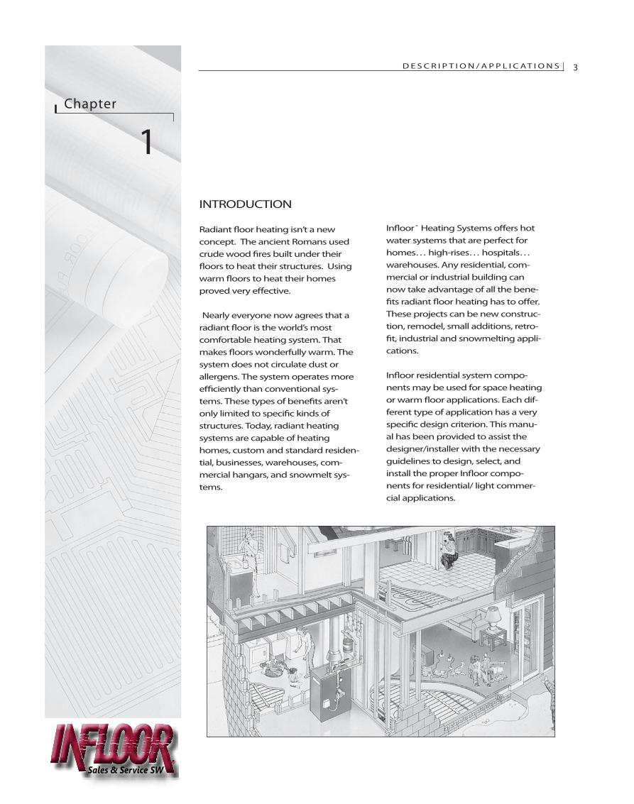
Radiant �oor heating isn’t a newconcept. The ancient Romans usedcrude wood �res built under their�oors to heat their structures. Usingwarm �oors to heat their homesproved very e�ective.
Nearly everyone now agrees that aradiant �oor is the world’s mostcomfortable heating system. Thatmakes �oors wonderfully warm. Thesystem does not circulate dust orallergens. The system operates moree�ciently than conventional sys-tems. These types of bene�ts aren’tonly limited to speci�c kinds ofstructures. Today, radiant heatingsystems are capable of heatinghomes, custom and standard residen-tial, businesses, warehouses, com-mercial hangars, and snowmelt sys-tems.
In�oor ® Heating Systems o�ers hotwater systems that are perfect forhomes… high-rises… hospitals…warehouses. Any residential, com-mercial or industrial building cannow take advantage of all the bene-�ts radiant �oor heating has to o�er.These projects can be new construc-tion, remodel, small additions, retro-�t, industrial and snowmelting appli-cations.
In�oor residential system compo-nents may be used for space heatingor warm �oor applications. Each dif-ferent type of application has a veryspeci�c design criterion. This manu-al has been provided to assist thedesigner/installer with the necessaryguidelines to design, select, andinstall the proper In�oor compo-nents for residential/ light commer-cial applications.
D E S C R I P T I O N / A P P L I C AT I O N S 3
Sales & Service SW
4 D E S C R I P T I O N / A P P L I C AT I O N SChapter 1
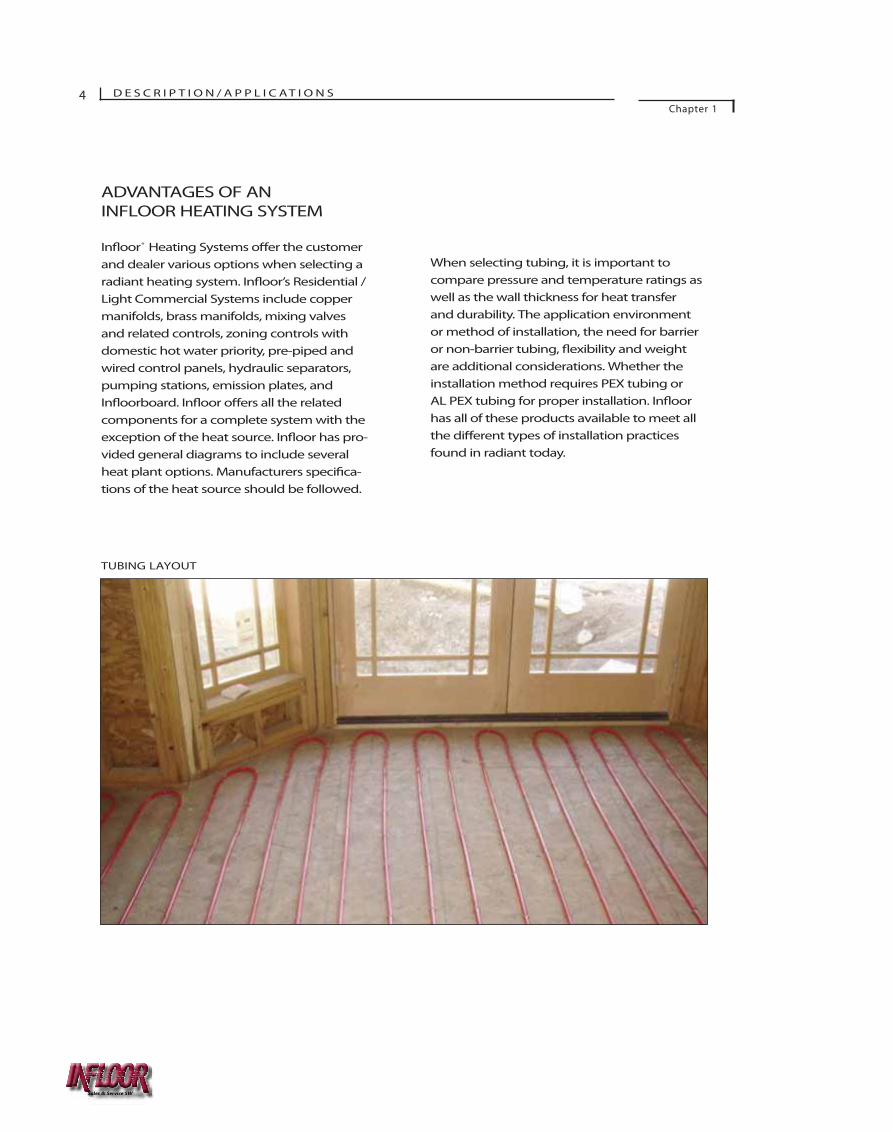
ADVANTAGES OF ANINFLOOR HEATING SYSTEM
oor® Heating Systems er the customerand dealer various options when selecting aradiant heating system. I oor’s Residential /Light Commercial Systems include coppermanifolds, brass manifolds, mixing valvesand related controls, zoning controls withdomestic hot water priority, pre-piped andwired control panels, hydraulic separators,pumping stations, emission plates, and
oorboard. In oor o ers all the relatedcomponents for a complete system with theexception of the heat source. has pro-vided general diagrams to include severalheat plant options. Manufacturers spec ca-tions of the heat source should be followed.
When selecting tubing, it is important tocompare pressure and temperature ratings aswell as the wall thickness for heat transferand durability. The application environmentor method of installation, the need for barrieror non-barrier tubing, y and weightare additional considerations. Whether theinstallation method requires PEX tubing orAL PEX tubing for proper installation. In oorhas all of these products available to meet allthe types of installation practicesfound in radiant today.
TUBING LAYOUT
Sales & Service SW
C O M P O N E N T S 5
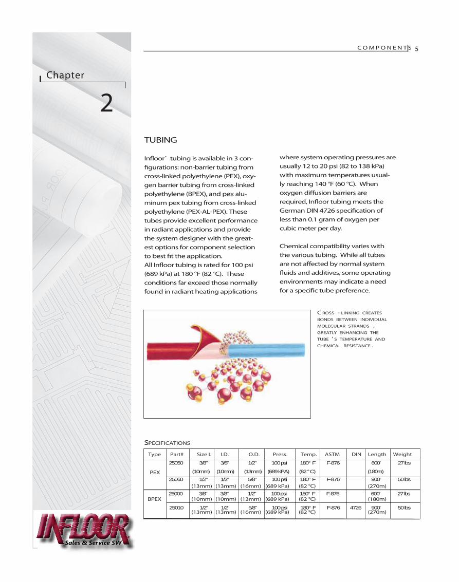
TUBING
In oor® tubing is available in 3 con-ations: non-barrier tubing from
cross-linked polyethylene (PEX), oxy-gen barrier tubing from cross-linkedpolyethylene (BPEX), and pex alu-minum pex tubing from cross-linkedpolyethylene (PEX-AL-PEX). Thesetubes provide excellent performancein radiant applications and providethe system designer with the great-est options for component selectionto best t the application.All In oor tubing is rated for 100 psi(689 kPa) at 180 °F (82 °C). Theseconditions far exceed those normallyfound in radiant heating applications
where system operating pressures are usually 12 to 20 psi (82 to 138 kPa)with maximum temperatures usual-ly reaching 140 °F (60 °C). Whenoxygen di usion barriers arerequired, In oor tubing meets theGerman DIN 4726 ion ofless than 0.1 gram of oxygen percubic meter per day.
Chemical compatibility varies withthe various tubing. While all tubesare not ected by normal system
and additives, some operatingenvironments may indicate a needfor a c tube preference.
PEX
(13mm) (13mm) (16mm) (689 kPa) (82 °C) (270m)
BPEX (10mm) (10mm) (13mm) (689 kPa) (82 °C) (180m)
(13mm) (13mm) (16mm) (689 kPa) (82 °C) (270m)
Chapter
2
C ROSS - LINKING CREATES
BONDS BETWEEN INDIVIDUAL
MOLECULAR STRANDS ,GREATLY ENHANCING THE
TUBE ’ S TEMPERATURE AND
CHEMICAL RESISTANCE .
SPECIFICATIONS
Type Part# Size L I.D. O.D. Press. Temp. ASTM DIN Length Weight
25050 3/8” 3/8” 1/2” 100 psi 180° F F-876 600’ 27 lbs
(10mm) (10mm) (13mm) (689 kPA) (82 ° C) (180m) 25060 1/2” 1/2” 5/8” 100 psi 180° F F-876 900’ 50 lbs
25000 3/8” 3/8” 1/2” 100 psi 180° F F-876 600’ 27 lbs
25010 1/2” 1/2” 5/8” 100 psi 180° F F-876 4726 900’ 50 lbs
Sales & Service SW
C O M P O N E N T SChapter 2
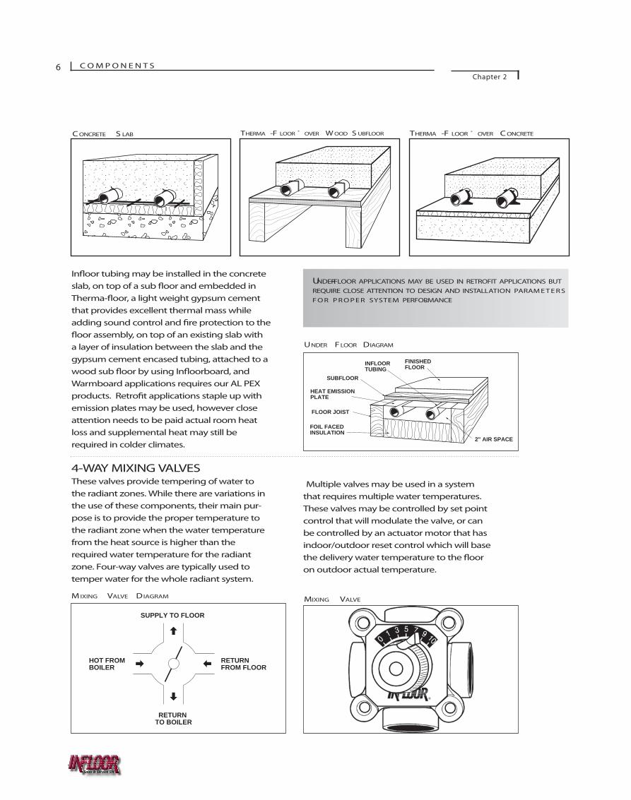
In�oor tubing may be installed in the concreteslab, on top of a sub �oor and embedded inTherma-�oor, a light weight gypsum cementthat provides excellent thermal mass whileadding sound control and �re protection to the�oor assembly, on top of an existing slab witha layer of insulation between the slab and thegypsum cement encased tubing, attached to awood sub �oor by using In�oorboard, andWarmboard applications requires our AL PEXproducts. Retro�t applications staple up withemission plates may be used, however closeattention needs to be paid actual room heatloss and supplemental heat may still berequired in colder climates.
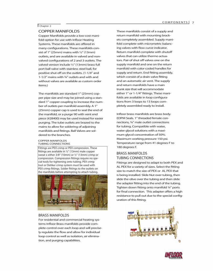
4-WAY MIXING VALVESThese valves provide tempering of water tothe radiant zones. While there are variations inthe use of these components, their main pur-pose is to provide the proper temperature tothe radiant zone when the water temperaturefrom the heat source is higher than therequired water temperature for the radiantzone. Four-way valves are typically used totemper water for the whole radiant system.
6
UNDER-FLOOR APPLICATIONS MAY BE USED IN RETROFIT APPLICATIONS BUTREQUIRE CLOSE ATTENTION TO DESIGN AND INSTALLATION PARAM E T E R SF O R P R O P E R SYSTEM PERFORMANCE.
INSULATION
BASE MATERIAL
INSULATION (OPTIONAL)
INSULATION
CONCRETE SLAB
C ONCRETE S LAB THERMA -F LOOR ® OVER C ONCRETETHERMA -F LOOR ® OVER W OOD S UBFLOOR
10
SUPPLY TO FLOOR
RETURN FROM FLOOR
HOT FROM BOILER
RETURN TO BOILER
M IXING VALVE DIAGRAM MIXING VALVE
Multiple valves may be used in a systemthat requires multiple water temperatures.These valves may be controlled by set pointcontrol that will modulate the valve, or canbe controlled by an actuator motor that hasindoor/outdoor reset control which will basethe delivery water temperature to the �ooron outdoor actual temperature.
61
FINISHED FLOOR
2" AIR SPACE
INFLOOR TUBING
FOIL FACED INSULATION
FLOOR JOIST
SUBFLOOR
HEAT EMISSION PLATE
UNDER FLOOR DIAGRAM
Sales & Service SW
C O M P O N E N T SChapter 2
7
COPPER MANIFOLDSCopper Manifolds provide a low-cost mani-fold option for use with In�oor HeatingSystems. These manifolds are o�ered inmany con�gurations. These manifolds con-sist of 1” (25mm) mains with ½” (13mm)outlets, and are available in valved and non-valved con�gurations of 2 and 3 outlets. Thevalved version include ½” (13mm) brass fullport ball valve with stainless steel ball, forpositive shut o� on the outlets. (1-1/4” and1-1/2” mains with ¾” outlets and with andwithout valves are available as custom orderitems.)
The manifolds are standard 1” (25mm) cop-per pipe size and may be joined using a stan-dard 1” copper coupling to increase the num-ber of outlets per manifold assembly. A 1”(25mm) copper cap is used to seal the end ofthe manifold, or a purge 90 with vent endpiece (#28400) may be used instead for easierpurging. The tube outlets are brazed to themains to allow for soldering of adjoiningmanifolds and �ttings. Ball Valves are sol-dered to the branches.
BRASS MANIFOLDSFor residential and commercial heating sys-tems In�oor Brass manifolds provide com-plete control over each loop and will precise-ly regulate the �ow and allow for individualloop control as well as isolation, air elimina-tion, and purging capabilities.
Fittings are PEX crimp or PEX compression. These�ttings are available in ½” (13mm) male coppersweat x either 3/8” (10mm) or ½” (13mm) crimp orcompression. Compression �ttings require no spe-cial tools for tightening onto tubing. PEX crimptool or Oetiker crimp system must be used withPEX crimp �ttings. Solder �ttings to the outlets onthe manifolds before attempting to attach tubing.
COPPER MANIFOLDSTUBING CONNECTIONS
These manifolds consist of a supply andreturn manifold with mounting brack-ets completely assembled. Supply mani-fold complete with micrometric balanc-ing valves with �ow curve indicator.Return manifold complete with shuto�valves that can utilize thermo actua-tors. Pair of shut o� valves one on thesupply manifold and one on the returnmanifold with color-coded handles forsupply and return. End �tting assembly,which consist of a drain valve �ttingand an automatic air vent. The supplyand return manifolds have a maintrunk size that will accommodateeither 1” or 1-1/4” �ttings. These mani-folds are available in loop con�gura-tions from 3 loops to 13 loops com-pletely assembled ready to install.
In�oor brass manifolds are brass body.EDPM Seals. 1” threaded female con-nections, ¾” male outlet connectionsfor tubing. Compatible with water,water glycol solutions with a maxi-mum glycol concentration of 50%.Maximum working pressure 150 psi.Temperature range from 41 degrees F to180 degrees F.
BRASS MANIFOLDSTUBING CONNECTIONSFittings are designed to adapt to both PEX andAL PEX for a variety of sizes. Select the �ttingsize to match the size of PEX or AL PEX thatis being installed. Slide Nut over tubing, thenslide the olive over the tubing and then slidethe adapter �tting into the end of the tubing.Tighten down �tting onto manifold ¾” portsfor �nal connection. This adapter o�ers a highresistance to pull out due to the special con�g-uration of this �tting.
Sales & Service SW
Chapter
3SITE PREPARATION
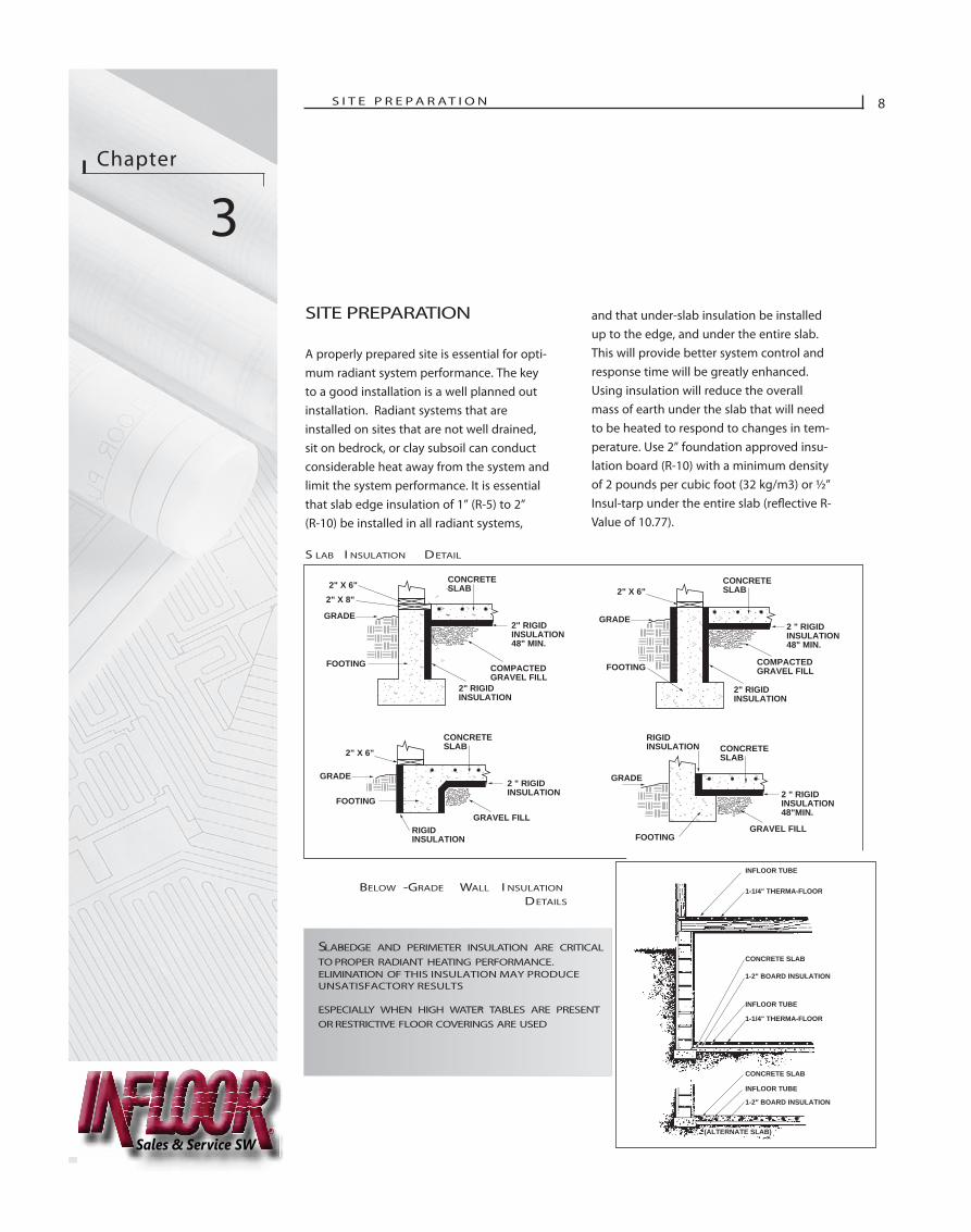
A properly prepared site is essential for opti-mum radiant system performance. The keyto a good installation is a well planned outinstallation. Radiant systems that areinstalled on sites that are not well drained,sit on bedrock, or clay subsoil can conductconsiderable heat away from the system andlimit the system performance. It is essentialthat slab edge insulation of 1” (R-5) to 2”(R-10) be installed in all radiant systems,
and that under-slab insulation be installedup to the edge, and under the entire slab.This will provide better system control andresponse time will be greatly enhanced.Using insulation will reduce the overallmass of earth under the slab that will needto be heated to respond to changes in tem-perature. Use 2” foundation approved insu-lation board (R-10) with a minimum densityof 2 pounds per cubic foot (32 kg/m3) or ½”Insul-tarp under the entire slab (re�ective R-Value of 10.77).
S I T E P R E P A R AT I O N 8
SLAB-EDGE AND PERIMETER INSULATION ARE CRITICALTO PROPER RADIANT HEATING PERFORMANCE.ELIMINATION OF THIS INSULATION MAY PRODUCEUNSATISFACTORY RESULTS
ESPECIALLY WHEN HIGH WATER TABLES ARE PRESENTOR RESTRICTIVE FLOOR COVERINGS ARE USED
.
14
COMPACTED GRAVEL FILL
CONCRETE SLAB
2" RIGID INSULATION 48" MIN.
2" RIGID INSULATION
2" X 6"2" X 8"
GRADE
FOOTING
COMPACTED GRAVEL FILL
CONCRETE SLAB
2 " RIGID INSULATION 48" MIN.
2" RIGID INSULATION
2" X 6"
GRADE
FOOTING
GRAVEL FILL
CONCRETE SLAB
2 " RIGID INSULATION
2 " RIGID INSULATION 48"MIN.
2" X 6"
GRADE
GRADE
FOOTING
GRAVEL FILL
CONCRETE SLAB
RIGID INSULATION RIGID
INSULATION
FOOTING
14
COMPACTED GRAVEL FILL
CONCRETE SLAB
2" RIGID INSULATION 48" MIN.
2" RIGID INSULATION
2" X 6"2" X 8"
GRADE
FOOTING
COMPACTED GRAVEL FILL
CONCRETE SLAB
2" RIGID INSULATION
2" X 6"
GRADE
FOOTING
GRAVEL FILL
CONCRETE SLAB
2 " RIGID INSULATION 48"MIN.
2" X 6"
GRADE
GRADE
FOOTING
GRAVEL FILL
CONCRETE SLAB
RIGID INSULATION RIGID
INSULATION
FOOTING
INFLOOR TUBE
1-1/4" THERMA-FLOOR
1-2" BOARD INSULATION
INFLOOR TUBE
1-1/4" THERMA-FLOOR
CONCRETE SLAB
INFLOOR TUBE
1-2" BOARD INSULATION
CONCRETE SLAB
(ALTERNATE SLAB)
S LAB I NSULATION DETAIL
BELOW -GRADE WALL I NSULATION
DETAILS
Sales & Service SW

S I T E P R E P A R AT I O NChapter 3
9
CONCRETE SLABS
All plumbing and electrical work inside the slab areashould be completed and inspected prior to installationof the radiant system. All trenches should be back and slab area should be raked at and compacted priorto installation of the under slab insulation. Vapor barri-er a minimum of 6 mil polyethylene should be used ifusing foundation-approved insulation such as poly-styrene. Using products such as Insul-tarp would notrequire the additional vapor barrier and installs rathereasily. Insulation should run underneath the entire slaband tie horizontally into slab edge insulation. All seamsin insulation should be taped. Next, lay 6” x 6” rein-forcing mesh over all the insulation in which radiantwill be installed. Adjoining sections should overlap by 6to 9 inches and be securely fastened together. The wiremesh is for securing tubing in place and use as a gridguideline for tubing attachment. All sharp edges of wiremesh should face away from tubing.
Layout with spray paint on top of the insulation all,rooms, walls, non heated areas, stairways, toilets andtubs and showers. Then refer to heat loss calculation forlayout of tubing based on radiant heating design.
IT MAY BE NECESSARY TO RECESS THE INITIAL EXCAVATIONTO ALLOW FOR THE ADDITION OF INSULATION UNDER THESLAB.
62
THERMA-FLOOR UNDERLAYMENT
INFLOOR TUBING
INSULATION (OPTIONAL)
FLOOR JOIST
SUBFLOOR
STAPLE
66
CONCRETE SLAB EDGE
INSULATIONINFLOOR TUBING
SLAB INSULATION
BASE MATERIAL
WIRE MESH OR REBAR
PLASTIC OR WIRE TIE
C ONCRETE S LAB
THERMA -F LOOR ® OVER W OOD S UBFLOOR
WOOD SUBFLOORS WITH GYPSUM
The oor must be clean, structurally sound andcontaminant free. Repair any weak or delaminatedareas. Remove studwall base plates in doorways andother areas to accommodate tubing layout.
Account for the change in oor elevation caused bythe addition of a Ther system, normally 1-1/2”. By using a double sill plate, the oor height isadjusted and window and door elevations remain thesame. Be sure to adjust stair risers and oor drains tomatch hed or height. Planning of nished
goods will help to determine height restrictions.
Layout grid on the oor using a tape measure and alumber crayon, measure in 6” from all walls andplace a mark. This mark will be the closest the tub-ing will need to be to the walls. Determine from theheat loss the tubing spacing for that particular area,normally 6” or 9”, then layout your grid in the roomeither 6” on center grid or a 9” on center grid. Thisgrid will assist as a guideline for installing the tub-ing.
Insulation
Sales & Service SW
S I T E P R E P A R AT I O NChapter 3
10
WARMBOARD
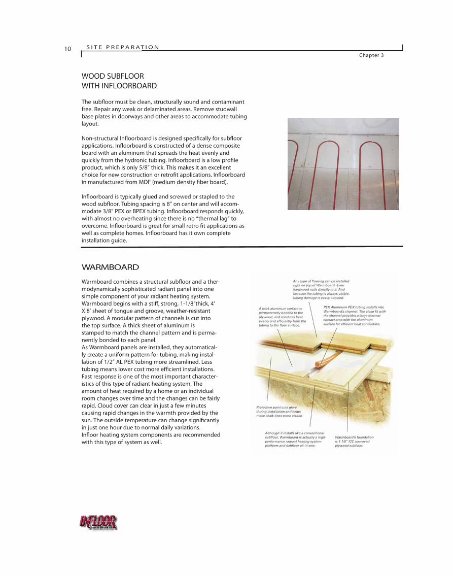
Warmboard combines a structural sub�oor and a ther-modynamically sophisticated radiant panel into onesimple component of your radiant heating system.Warmboard begins with a sti�, strong, 1-1/8”thick, 4’X 8’ sheet of tongue and groove, weather-resistantplywood. A modular pattern of channels is cut intothe top surface. A thick sheet of aluminum isstamped to match the channel pattern and is perma-nently bonded to each panel.As Warmboard panels are installed, they automatical-ly create a uniform pattern for tubing, making instal-lation of 1/2” AL PEX tubing more streamlined. Lesstubing means lower cost more e�cient installations.Fast response is one of the most important character-istics of this type of radiant heating system. Theamount of heat required by a home or an individualroom changes over time and the changes can be fairlyrapid. Cloud cover can clear in just a few minutescausing rapid changes in the warmth provided by thesun. The outside temperature can change signi�cantlyin just one hour due to normal daily variations.In�oor heating system components are recommendedwith this type of system as well.
WOOD SUBFLOORWITH INFLOORBOARD
The sub�oor must be clean, structurally sound and contaminantfree. Repair any weak or delaminated areas. Remove studwallbase plates in doorways and other areas to accommodate tubinglayout.
Non-structural In�oorboard is designed speci�cally for sub�oorapplications. In�oorboard is constructed of a dense compositeboard with an aluminum that spreads the heat evenly andquickly from the hydronic tubing. In�oorboard is a low pro�leproduct, which is only 5/8” thick. This makes it an excellentchoice for new construction or retro�t applications. In�oorboardin manufactured from MDF (medium density �ber board).
In�oorboard is typically glued and screwed or stapled to thewood sub�oor. Tubing spacing is 8” on center and will accom-modate 3/8” PEX or BPEX tubing. In�oorboard responds quickly,with almost no overheating since there is no “thermal lag” toovercome. In�oorboard is great for small retro �t applications aswell as complete homes. In�oorboard has it own completeinstallation guide.
Sales & Service SW
S I T E P R E P E R AT I O NChapter 3
11
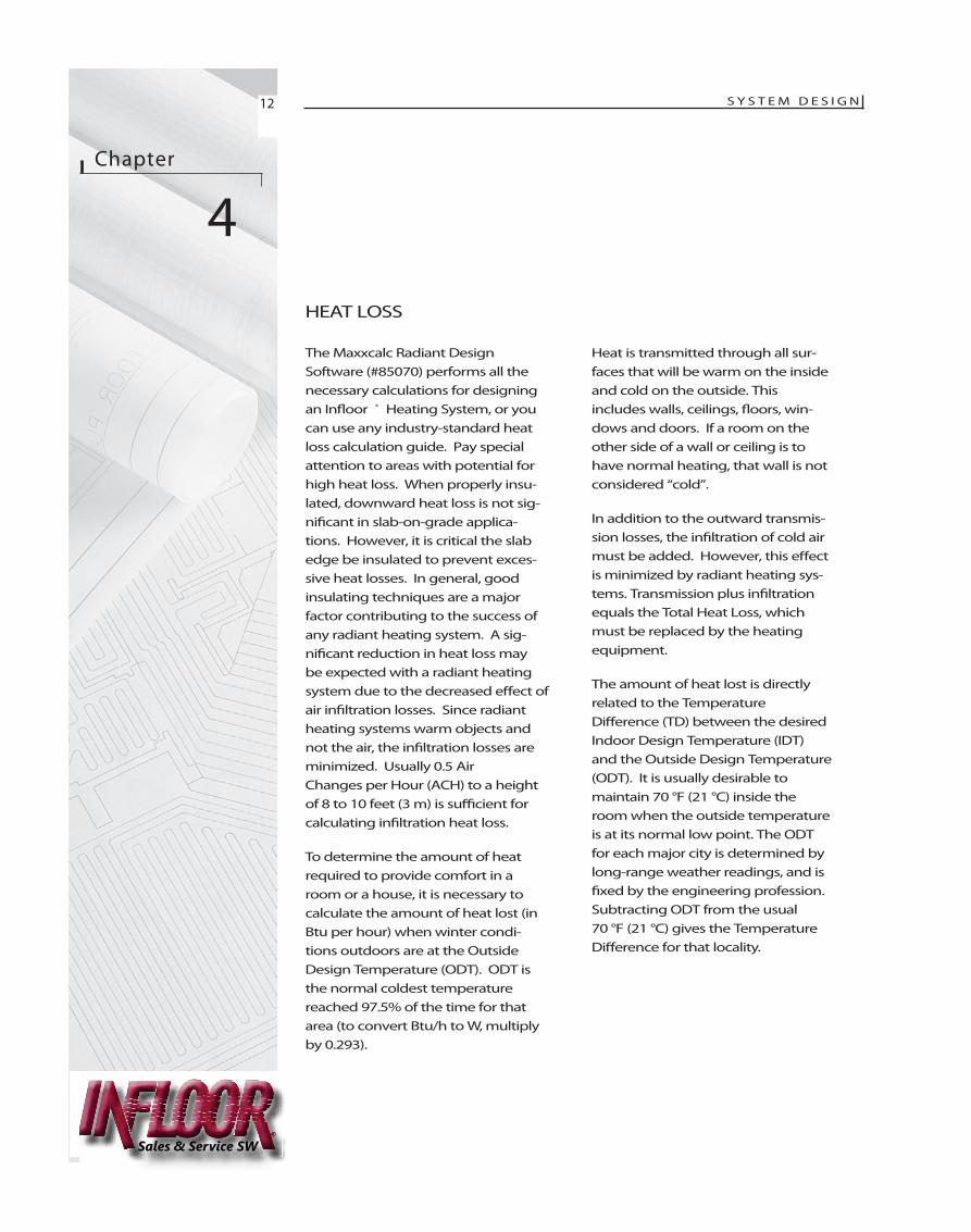
PRECAST CONCRETESUBFLOORS
The sub�oor must be clean and contaminant free. Incold climates it is highly recommended that someinsulation be placed on top of the existing slab toenhance the response time and reduce the amount ofdownward loss to the existing slab. Mechanically fas-ten 6” x 6” wire welded mesh to the concrete sub-�oor using concrete screws. Fasten the wire meshtightly to �oor to prevent the �oating of tubing.
Attach the tubing to the wire mesh using In�oor wireties (#26001) or plastic ties (#26005). When 1” orthicker insulation is installed over the existing con-crete sub�oor, In�oor screw clips (#26015) may beused. The screw clip will secure In�oor 3/8” (10mm)and ½” (13mm) tubing. In�oor also o�ers the insula-tion tacker tool (#26085), which allows for installa-tion of plastic staples (#26081) into the insulation fortube attachment.
64
THERMA-FLOOR UNDERLAYMENT
SLAB INSULATION
CONCRETE SLAB
SCREW CLIPINFLOOR TUBING
THERMA -F LOOR® OVER CONCRETE
WOOD SUBFLOOR WITHSTAPLE UP WITH EMISSION PLATES
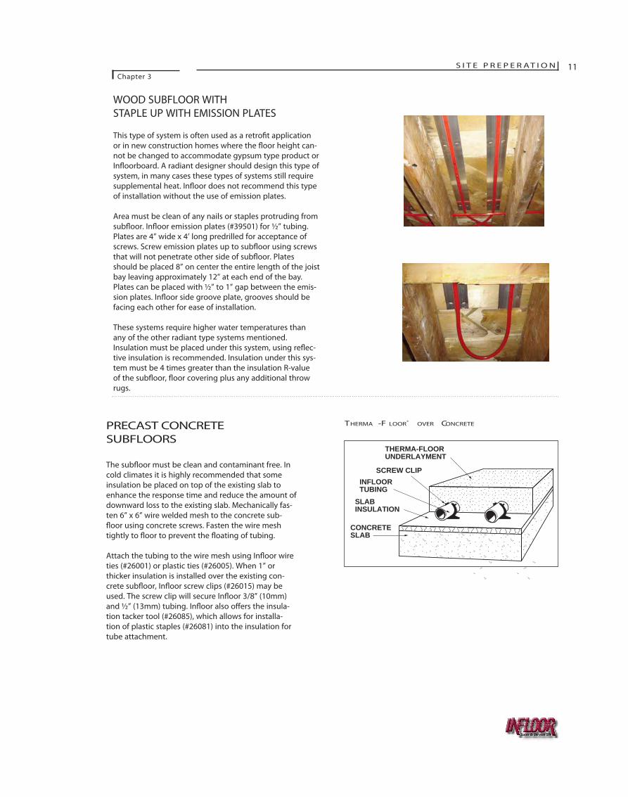
This type of system is often used as a retro�t applicationor in new construction homes where the �oor height can-not be changed to accommodate gypsum type product orIn�oorboard. A radiant designer should design this type ofsystem, in many cases these types of systems still requiresupplemental heat. In�oor does not recommend this typeof installation without the use of emission plates.
Area must be clean of any nails or staples protruding fromsub�oor. In�oor emission plates (#39501) for ½” tubing.Plates are 4” wide x 4’ long predrilled for acceptance ofscrews. Screw emission plates up to sub�oor using screwsthat will not penetrate other side of sub�oor. Platesshould be placed 8” on center the entire length of the joistbay leaving approximately 12” at each end of the bay.Plates can be placed with ½” to 1” gap between the emis-sion plates. In�oor side groove plate, grooves should befacing each other for ease of installation.
These systems require higher water temperatures thanany of the other radiant type systems mentioned.Insulation must be placed under this system, using re�ec-tive insulation is recommended. Insulation under this sys-tem must be 4 times greater than the insulation R-valueof the sub�oor, �oor covering plus any additional throwrugs.
Sales & Service SW
Chapter
4HEAT LOSS
The Maxxcalc Radiant DesignSoftware (#85070) performs all thenecessary calculations for designingan In�oor ® Heating System, or youcan use any industry-standard heatloss calculation guide. Pay specialattention to areas with potential forhigh heat loss. When properly insu-lated, downward heat loss is not sig-ni�cant in slab-on-grade applica-tions. However, it is critical the slabedge be insulated to prevent exces-sive heat losses. In general, goodinsulating techniques are a majorfactor contributing to the success ofany radiant heating system. A sig-ni�cant reduction in heat loss maybe expected with a radiant heatingsystem due to the decreased e�ect ofair in�ltration losses. Since radiantheating systems warm objects andnot the air, the in�ltration losses areminimized. Usually 0.5 AirChanges per Hour (ACH) to a heightof 8 to 10 feet (3 m) is su�cient forcalculating in�ltration heat loss.
To determine the amount of heatrequired to provide comfort in aroom or a house, it is necessary tocalculate the amount of heat lost (inBtu per hour) when winter condi-tions outdoors are at the OutsideDesign Temperature (ODT). ODT isthe normal coldest temperaturereached 97.5% of the time for thatarea (to convert Btu/h to W, multiplyby 0.293).
Heat is transmitted through all sur-faces that will be warm on the insideand cold on the outside. Thisincludes walls, ceilings, �oors, win-dows and doors. If a room on theother side of a wall or ceiling is tohave normal heating, that wall is notconsidered “cold”.
In addition to the outward transmis-sion losses, the in�ltration of cold airmust be added. However, this e�ectis minimized by radiant heating sys-tems. Transmission plus in�ltrationequals the Total Heat Loss, whichmust be replaced by the heatingequipment.
The amount of heat lost is directlyrelated to the TemperatureDi�erence (TD) between the desiredIndoor Design Temperature (IDT)and the Outside Design Temperature(ODT). It is usually desirable tomaintain 70 °F (21 °C) inside theroom when the outside temperatureis at its normal low point. The ODTfor each major city is determined bylong-range weather readings, and is�xed by the engineering profession.Subtracting ODT from the usual 70 °F (21 °C) gives the TemperatureDi�erence for that locality.
S Y S T E M D E S I G N12
Sales & Service SW
S Y S T E M D E S I G NChapter 4
13
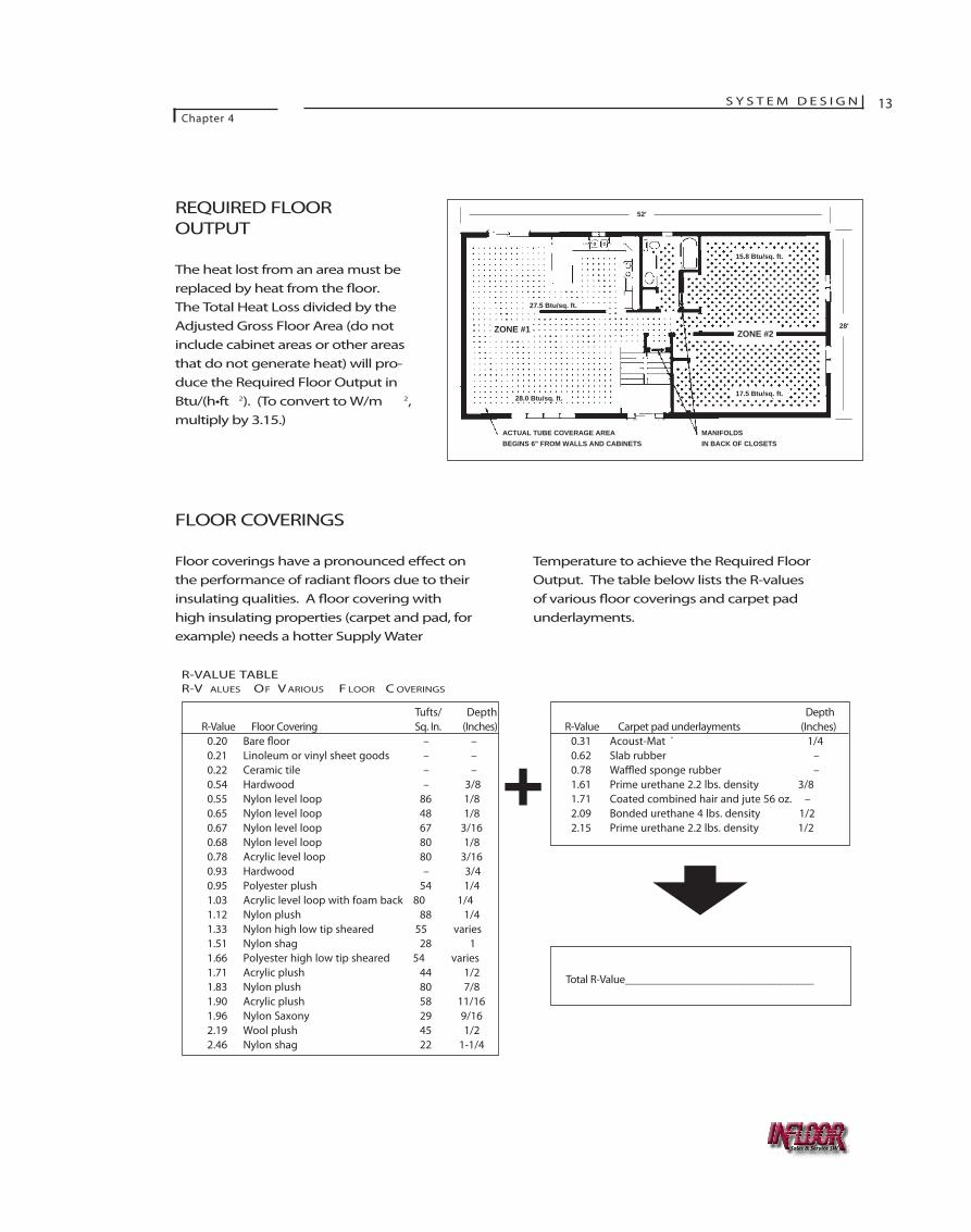
REQUIRED FLOOROUTPUT
The heat lost from an area must bereplaced by heat from the �oor.The Total Heat Loss divided by theAdjusted Gross Floor Area (do notinclude cabinet areas or other areasthat do not generate heat) will pro-duce the Required Floor Output inBtu/(h•ft 2). (To convert to W/m 2,multiply by 3.15.)
Temperature to achieve the Required FloorOutput. The table below lists the R-valuesof various �oor coverings and carpet padunderlayments.
FLOOR COVERINGS
Floor coverings have a pronounced e�ect onthe performance of radiant �oors due to theirinsulating qualities. A �oor covering withhigh insulating properties (carpet and pad, forexample) needs a hotter Supply Water
ACTUAL TUBE COVERAGE AREA BEGINS 6" FROM WALLS AND CABINETS
MANIFOLDS IN BACK OF CLOSETS
52'
28'ZONE #1 ZONE #2
17.5 Btu/sq. ft.
15.8 Btu/sq. ft.
27.5 Btu/sq. ft.
28.0 Btu/sq. ft.
R-VALUE TABLER-V ALUES OF V ARIOUS F LOOR C OVERINGS
Tufts/ DepthR-Value Floor Covering Sq. In. (Inches)
0.20 Bare �oor – –0.21 Linoleum or vinyl sheet goods – –0.22 Ceramic tile – –0.54 Hardwood – 3/80.55 Nylon level loop 86 1/80.65 Nylon level loop 48 1/80.67 Nylon level loop 67 3/160.68 Nylon level loop 80 1/80.78 Acrylic level loop 80 3/160.93 Hardwood – 3/40.95 Polyester plush 54 1/41.03 Acrylic level loop with foam back 80 1/41.12 Nylon plush 88 1/41.33 Nylon high low tip sheared 55 varies1.51 Nylon shag 28 11.66 Polyester high low tip sheared 54 varies1.71 Acrylic plush 44 1/21.83 Nylon plush 80 7/81.90 Acrylic plush 58 11/161.96 Nylon Saxony 29 9/162.19 Wool plush 45 1/22.46 Nylon shag 22 1-1/4
DepthR-Value Carpet pad underlayments (Inches)
0.31 Acoust-Mat ® 1/40.62 Slab rubber –0.78 Wa�ed sponge rubber –1.61 Prime urethane 2.2 lbs. density 3/81.71 Coated combined hair and jute 56 oz. –2.09 Bonded urethane 4 lbs. density 1/22.15 Prime urethane 2.2 lbs. density 1/2
Total R-Value__________________________________
+
Sales & Service SW
14 S Y S T E M D E S I G NChapter 4
While it may be most desirable to have auniform surface temperature across theentire oor, it is not economically possible toembed tubing in every inch of oor space.As tubes are spaced further apart, the oorsurface temperature varies depending on thedistance between the tubes. When tubes arespaced too far apart, warm and cold spotsmay be felt across the oor. This is not onlyless comfortable, but also impedes the abilityof the oor to transfer heat and may result inunwanted temperature swings in the room.Wide tube spacing also requires higher watertemperatures to e ectively heat the room.
ACTUAL FLOOR OUTPUT ANDDELIVERY WATERTEMPERATURE
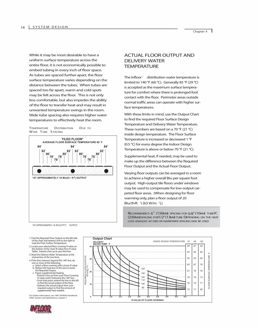
The or ® distribution water temperature islimited to 140 °F (60 °C). Generally 85 °F (29 °C)is accepted as the maximum surface tempera-ture for comfort where there is prolonged footcontact with the oor. Perimeter areas outsidenormal tr c areas can operate with higher sur-face temperatures.
With these limits in mind, use the Output Chartto d the required Floor Surface DesignTemperature and Delivery Water Temperature.These numbers are based on a 70 °F (21 °C)inside design temperature. The Floor SurfaceTemperature is increased or decreased 1 °F (0.5 °C) for every degree the Indoor DesignTemperature is above or below 70 °F (21 °C).
Supplemental heat, if needed, may be used tomake up the di erence between the RequiredFloor Output and the Actual Floor Output.
Varying oor outputs can be averaged in a roomto achieve a higher overall Btu per square footoutput. High-output tile oors under windowsmay be used to compensate for low-output car-peted oor areas. (When designing for rwarming only, plan a oor output of 20Btu/(h•ft 2) [63 W/m 2].)
40
30
20
10
0 .5 1.0 2.01.5 2.5 3.0 3.5 4.0 4.5 5.0
RE
QU
IRE
D F
LOO
R O
UTP
UT8
BTU
/SQ
. FT
FLO
OR
SU
RFA
CE
TE
MP
ER
ATU
RE
˚F
INSIDE DESIGN TEMPERATURE
140˚
130˚
120˚110˚
100˚
90˚
Output ChartDELIVERY WATER TEMP. ˚F
R-VALUE OF FLOOR COVERING
89˚
87˚
85˚
83˚
81˚
78˚
76˚
73˚
87˚
85˚
83˚
81˚
79˚
76˚
74˚
71˚
84˚
70˚ 68˚ 65˚
82˚
80˚
78˚
76˚
73˚
71˚
68˚
1. Find the Required Floor Output on the left side of the chart and extend a line to the right to read the Floor Surface Temperature.
2. Locate your selected oor covering R-value on the bottom of the chart (R-value from R-value Table). Extend a line up to your rst line.
3. Read the Delivery Water Temperature at the intersection of the two lines.
4. If the lines intersect beyond the 140° line, do one or more of the following:a. Select a oor covering with a lower R-valueb. Reduce the heat loss of the area to lower
the Required Output.c. Figure supplemental heating.
–Extend a line up from your Floor Covering R-value until it intersects the 140° line.
–From that point, extend the line to the left to the actual output of the oor.
–Subtract the actual output from your required output to nd the amount of supplemental heat needed.
For further information, see 1987 ASHRAE Handbook,HVAC System and Applications, chapter 7.
RECOMMENDED: 6" (150 MM) SPACING FOR 3/8" (10 MM) TUBE , 9"(230 MM) SPACING FOR1/2" (13 MM) TUBE. DEPENDING ON THE HEATLOSS ANALYSIS, WI DER OR NARROWER SPACING MAY BE USED.
84˚ 84˚82˚ 82˚
84˚82˚
80˚ 80˚78˚ 78˚
76˚
80˚78˚
76˚
82˚80˚
78˚
TILED FLOOR* AVERAGE FLOOR SURFACE TEMPERATURE 80 ˚F
*AT APPROXIMATELY 18 Btu/(h • ft ) OUTPUT
84˚ 84˚82˚ 82˚
84˚82˚
80˚ 80˚78˚ 78˚
76˚
80˚78˚
76˚
82˚80˚
78˚
CARPETED FLOOR (R-1.7)* AVERAGE FLOOR SURFACE TEMPERATURE 80 ˚F
2
*AT APPROXIMATELY 18 BTU/H*FT2
) OUTPUT
TEMPERATURE DISTRIBUTION DUE TO
W IDE TUBE S PACING
Sales & Service SW
S Y S T E M D E S I G NChapter 4
15
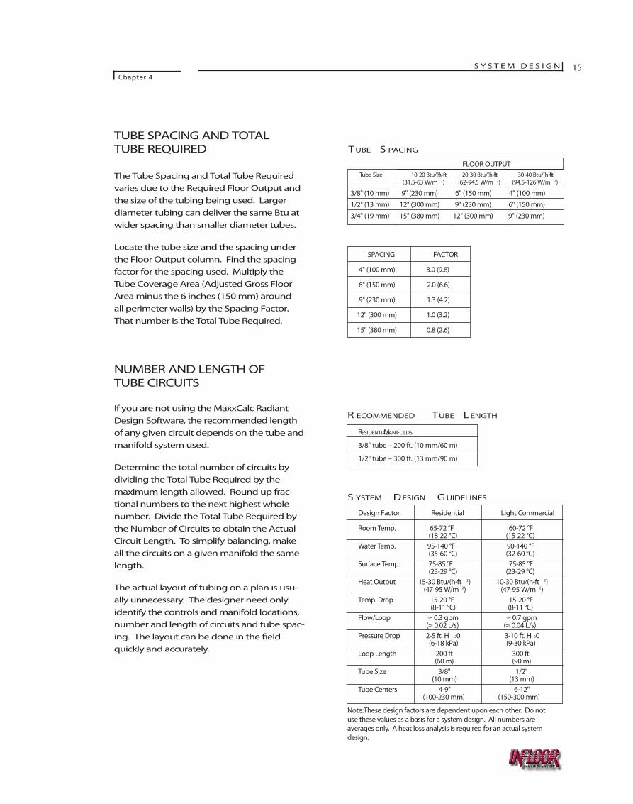
TUBE SPACING AND TOTALTUBE REQUIRED
The Tube Spacing and Total Tube Requiredvaries due to the Required Floor Output andthe size of the tubing being used. Largerdiameter tubing can deliver the same Btu atwider spacing than smaller diameter tubes.
Locate the tube size and the spacing underthe Floor Output column. Find the spacingfactor for the spacing used. Multiply theTube Coverage Area (Adjusted Gross FloorArea minus the 6 inches (150 mm) aroundall perimeter walls) by the Spacing Factor.That number is the Total Tube Required.
NUMBER AND LENGTH OFTUBE CIRCUITS
If you are not using the MaxxCalc RadiantDesign Software, the recommended length of any given circuit depends on the tube andmanifold system used.
Determine the total number of circuits bydividing the Total Tube Required by themaximum length allowed. Round up frac-tional numbers to the next highest wholenumber. Divide the Total Tube Required bythe Number of Circuits to obtain the ActualCircuit Length. To simplify balancing, makeall the circuits on a given manifold the samelength.
The actual layout of tubing on a plan is usu-ally unnecessary. The designer need onlyidentify the controls and manifold locations,number and length of circuits and tube spac-ing. The layout can be done in the �eldquickly and accurately.
Tube Size 10-20 Btu/(h•ft2) 20-30 Btu/(h•ft2) 30-40 Btu/(h•ft2)(31.5-63 W/m 2) (62-94.5 W/m 2) (94.5-126 W/m 2)
3/8" (10 mm) 9" (230 mm) 6" (150 mm) 4" (100 mm)1/2" (13 mm) 12" (300 mm) 9" (230 mm) 6" (150 mm)3/4" (19 mm) 15" (380 mm) 12" (300 mm) 9" (230 mm)
SPACING FACTOR
4" (100 mm) 3.0 (9.8)
6" (150 mm) 2.0 (6.6)
9" (230 mm) 1.3 (4.2)
12" (300 mm) 1.0 (3.2)
15" (380 mm) 0.8 (2.6)
RESIDENTIALMANIFOLDS
3/8" tube – 200 ft. (10 mm/60 m)
1/2" tube – 300 ft. (13 mm/90 m)
Design Factor Residential Light Commercial
Room Temp. 65-72 °F 60-72 °F(18-22 °C) (15-22 °C)
Water Temp. 95-140 °F 90-140 °F(35-60 °C) (32-60 °C)
Surface Temp. 75-85 °F 75-85 °F(23-29 °C) (23-29 °C)
Heat Output 15-30 Btu/(h•ft 2) 10-30 Btu/(h•ft 2)(47-95 W/m 2) (47-95 W/m 2)
Temp. Drop 15-20 °F 15-20 °F(8-11 °C) (8-11 °C)
Flow/Loop ≈ 0.3 gpm ≈ 0.7 gpm(≈ 0.02 L/s) (≈ 0.04 L/s)
Pressure Drop 2-5 ft. H 20 3-10 ft. H 20(6-18 kPa) (9-30 kPa)
Loop Length 200 ft 300 ft.(60 m) (90 m)
Tube Size 3/8" 1/2"(10 mm) (13 mm)
Tube Centers 4-9" 6-12"(100-230 mm) (150-300 mm)
TUBE S PACING
R ECOMMENDED TUBE L ENGTH
S YSTEM DESIGN G UIDELINES
Note: These design factors are dependent upon each other. Do notuse these values as a basis for a system design. All numbers areaverages only. A heat loss analysis is required for an actual systemdesign.
FLOOR OUTPUT
Sales & Service SW
16 D E S C R I P T I O N / A P P L I C AT I O N SChapter 1
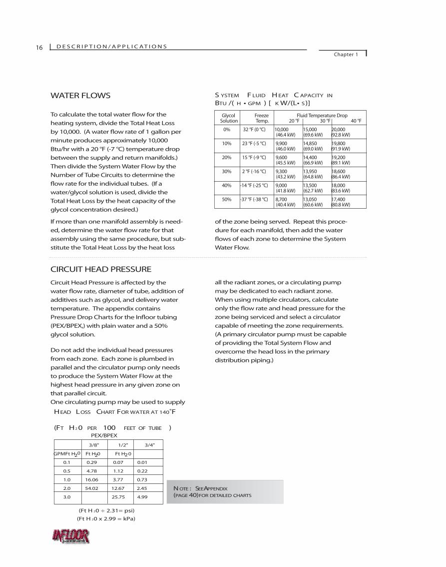
WATER FLOWS
To calculate the total water ow for theheating system, divide the Total Heat Lossby 10,000. (A water rate of 1 gallon perminute produces approximately 10,000Btu/hr with a 20 °F (-7 °C) temperature dropbetween the supply and return manifolds.)Then divide the System Water Flow by theNumber of Tube Circuits to determine the
ow rate for the individual tubes. (If awater/glycol solution is used, divide theTotal Heat Loss by the heat capacity of theglycol concentration desired.)
If more than one manifold assembly is need-ed, determine the water ow rate for thatassembly using the same procedure, but sub-stitute the Total Heat Loss by the heat loss
of the zone being served. Repeat this proce-dure for each manifold, then add the water
of each zone to determine the SystemWater Flow.
CIRCUIT HEAD PRESSURE
Circuit Head Pressure is a by thewater w rate, diameter of tube, addition ofadditives such as glycol, and delivery watertemperature. The appendix containsPressure Drop Charts for the I tubing(PEX/BPEX,) with plain water and a 50% glycol solution.
Do not add the individual head pressuresfrom each zone. Each zone is plumbed inparallel and the circulator pump only needsto produce the System Water Flow at thehighest head pressure in any given zone onthat parallel circuit. One circulating pump may be used to supply
all the radiant zones, or a circulating pumpmay be dedicated to each radiant zone.When using multiple circulators, calculateonly the rate and head pressure for thezone being serviced and select a circulatorcapable of meeting the zone requirements.(A primary circulator pump must be capableof providing the Total System Flow and overcome the head loss in the primary distribution piping.)
S YSTEM F LUID H EAT C APACITY IN
BTU /( H • GPM ) [ K W/(L• S)]
Glycol Freeze Fluid Temperature DropSolution Temp. 20 °F 30 °F 40 °F
0% 32 °F (0 °C) 10,000 15,000 20,000(46.4 kW) (69.6 kW) (92.8 kW)
10% 23 °F (-5 °C) 9,900 14,850 19,800(46.0 kW) (69.0 kW) (91.9 kW)
20% 15 °F (-9 °C) 9,600 14,400 19,200(45.5 kW) (66.9 kW) (89.1 kW)
30% 2 °F (-16 °C) 9,300 13,950 18,600(43.2 kW) (64.8 kW) (86.4 kW)
40% -14 °F (-25 °C) 9,000 13,500 18,000(41.8 kW) (62.7 kW) (83.6 kW)
50% -37 °F (-38 °C) 8,700 13,050 17,400(40.4 kW) (60.6 kW) (80.8 kW)
3/8" 1/2" 3/4"
GPMFt H 2 Ft H20 Ft H20
0.1 0.29 0.07 0.01
0.5 4.78 1.12 0.22
1.0 16.06 3.77 0.73
2.0 54.02 12.67 2.45
3.0 25.75 4.99
HEAD LOSS CHART FOR WATER AT 140˚F
(FT H2 0 PER 100 FEET OF TUBE )PEX/BPEX
(Ft H 20 ÷ 2.31= psi)
(Ft H 20 x 2.99 = kPa)
N OTE : SEEAPPENDIX(PAGE 40) FOR DETAILED CHARTS.
Sales & Service SW
0
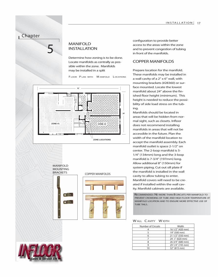
con�guration to provide betteraccess to the areas within the zoneand to prevent congestion of tubingin front of the manifolds.
COPPER MANIFOLDS
Prepare location for the manifold.These manifolds may be installed ina wall cavity of a 2” x 6” wall, withmounting brackets (#28360) or sur-face mounted. Locate the lowestmanifold about 24” above the �n-ished �oor height (minimum). Thisheight is needed to reduce the possi-bility of side load stress on the tub-ing. Manifolds should be located inareas that will be hidden from nor-mal sight, such as closets. In�oordoes not recommend installingmanifolds in areas that will not beaccessible in the future. Plan thewidth of the manifold location toaccept the manifold assembly. Eachmanifold outlet is space 2-1/2” oncenter. The 2-loop manifold is 5-1/4” (134mm) long and the 3-loopmanifold is 7-3/4” (197mm) long.Allow additional 8” (150mm) forsystem piping. Cut out sill plate ifthe manifold is installed in the wallcavity to allow tubing to enter.Manifold covers will need to be cre-ated if installed within the wall cav-ity. Manifold cabinets are available.
Chapter
5MANIFOLDINSTALLATION
Determine how zoning is to be done.Locate manifolds as centrally as pos-sible within the zone. Manifoldsmay be installed in a split
I N S TA L L AT I O N 17
ACTUAL TUBE COVERAGE AREA BEGINS 6" FROM WALLS AND CABINETS
ZONE CONTROL IN BACK OF CLOSETS
52'
28'
ZONE #1 ZONE #2
ZONE CONTROL IN BACK OF CLOSETS
ZONE LOCATIONS
RECOMMENDED: NO MORE THAN 8 CIRCUITS PER MANIFOLD TOPREVENT CROWDING OF TUBE AND HIGH FLOOR TEMPERATURE ATMANIFOLD LOCATION AND TO ENSURE MORE EFFECTIVE USE OFTUBE TAILS.
F LOOR P LAN WITH M ANIFOLD L OCATIONS
MANIFOLDMOUNTINGBRACKETS
Number of Circuits Width4 16 1/2" (420 mm)5 19" (500 mm)6 21 1/2" (550 mm)7 24 1⁄4" (620 mm)8 26 3/4" (680 mm)9 29 1/4" (745 mm)
10 32" (815 mm)
W ALL C AVITY W IDTH
COPPER MANIFOLDS
Sales & Service SW
Sales & Service SW
18 I N S TA L L AT I O NChapter 5
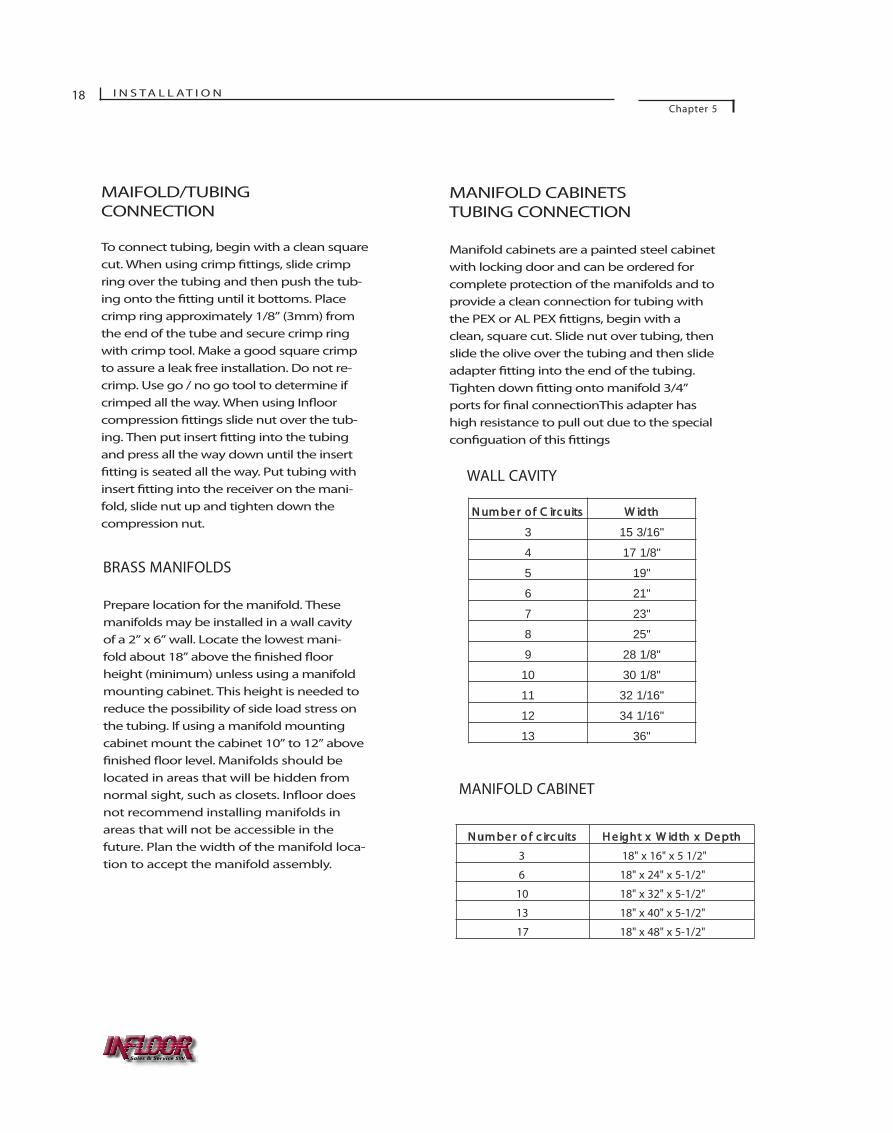
MAIFOLD/TUBINGCONNECTION
To connect tubing, begin with a clean squarecut. When using crimp �ttings, slide crimpring over the tubing and then push the tub-ing onto the �tting until it bottoms. Placecrimp ring approximately 1/8” (3mm) fromthe end of the tube and secure crimp ringwith crimp tool. Make a good square crimpto assure a leak free installation. Do not re-crimp. Use go / no go tool to determine ifcrimped all the way. When using In�oorcompression �ttings slide nut over the tub-ing. Then put insert �tting into the tubingand press all the way down until the insert�tting is seated all the way. Put tubing withinsert �tting into the receiver on the mani-fold, slide nut up and tighten down thecompression nut.
MANIFOLD CABINETSTUBING CONNECTION
Manifold cabinets are a painted steel cabinetwith locking door and can be ordered forcomplete protection of the manifolds and toprovide a clean connection for tubing withthe PEX or AL PEX �ttigns, begin with aclean, square cut. Slide nut over tubing, thenslide the olive over the tubing and then slideadapter �tting into the end of the tubing.Tighten down �tting onto manifold 3/4”ports for �nal connectionThis adapter hashigh resistance to pull out due to the specialcon�guation of this �ttings
N um be r o f C irc uits W idth
3 15 3/16"
4 17 1/8"
5 19"
6 21"
7 23"
8 25"
9 28 1/8"
10 30 1/8"
11 32 1/16"
12 34 1/16"
13 36"
WALL CAVITY
N um be r o f c irc uits H e ig ht x W idth x D e pth
3 18" x 16" x 5 1/2"
6 18" x 24" x 5-1/2"
10 18" x 32" x 5-1/2"
13 18" x 40" x 5-1/2"
17 18" x 48" x 5-1/2"
MANIFOLD CABINET
BRASS MANIFOLDS
Prepare location for the manifold. Thesemanifolds may be installed in a wall cavityof a 2” x 6” wall. Locate the lowest mani-fold about 18” above the �nished �oorheight (minimum) unless using a manifoldmounting cabinet. This height is needed toreduce the possibility of side load stress onthe tubing. If using a manifold mountingcabinet mount the cabinet 10” to 12” above�nished �oor level. Manifolds should belocated in areas that will be hidden fromnormal sight, such as closets. In�oor doesnot recommend installing manifolds inareas that will not be accessible in thefuture. Plan the width of the manifold loca-tion to accept the manifold assembly.
INSTALL TUBE
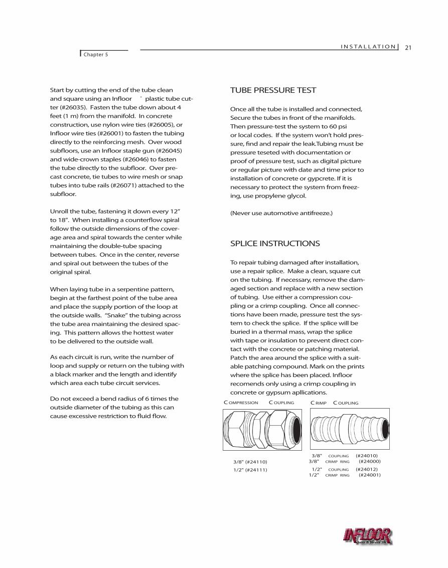
To make installation easier, In�oor ® tube hasfoot markings so it can be installed withoutactually measuring its length. All tubingshould be 6" (150 mm) away from walls andcabinets. Do not place tubes in areas whereequipment will be bolted to the �oor. Donot make bends tighter than 6" (150 mm) for3/8" (10 mm) tube; or 9" (230 mm) for 1/2"(13 mm) tube. Protect any tubes passingthrough expansion joints or control joints byrunning tubing to the bottom of the slab andplace a “sleeve” of pipe insulation or largerdiameter tubing around the In�oor tubes atthe expansion joint. Also use a protectivesleeve when tubes exit the slab. For installa-tion over wood sub�oors or precast planks,group tubes together when passing throughdoorways and cover with a nail guard.
SLEEVING DETAIL
DO NOT ALLOW TUBING TO CROSS OVER ITSELF AS THIS MAY PROVIDE INSUF-FICIENT THERMAL MASS COVERAGE AND MAYCREATE CRACKS IN THE CONCRETE SLAB.
“SLEEVE” TUBING AT EXPANSION JOINTS. ROUTE TUBING TO THE BOTTOM OF SLAB AND SLEEVE THROUGH EPANSION JOINTS.
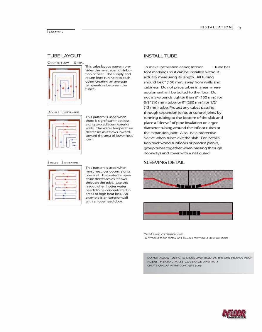
TUBE LAYOUTC OUNTERFLOW S PIRAL
DOUBLE S ERPENTINE
S INGLE S ERPENTINE
This tube layout pattern pro-vides the most even distribu-tion of heat. The supply andreturn lines run next to eachother, creating an averagetemperature between thetubes.
This pattern is used whenthere is signi�cant heat lossalong two adjacent exteriorwalls. The water temperaturedecreases as it �ows inward,toward the area of lower heatloss.
This pattern is used whenmost heat loss occurs alongone wall. The water temper-ature decreases as it �owsthrough the tube. Use thislayout when hotter waterneeds to be concentrated inareas of high heat loss. Anexample is an exterior wallwith an overhead door.
I N S TA L L AT I O NChapter 5
19
Sales & Service SW

20 I N S TA L L AT I O N
Chapter 5
CALCULATIONS
These calculations apply for all tube layoutpatterns. If you are not using the MaxxCalccomputer program to calculate circuitlength, use the recommended length asshown below. Start at one end of the mani-fold and plan to work from one extreme sideof the space toward the other with each suc-cessive circuit.
Determine the amount of tube needed to getfrom the manifold to the far corner of thezone and back. This length of tube is calledthe “tails.” Subtract the tails from the over-all circuit length. The result is the amountof tube available for the tube pattern.
Calculate the tube coverage by dividing theremaining tube by the spacing factor. Thisdetermines the square feet to be covered bythe circuit. Measure the width of the zone(Dimension A) and subtract 1 foot (for the 6-inch setback from each wall). Then sub-tract 2 times the tube spacing (the distancetaken by the tails). This adjusted width isthe dimension available after the tails are run.
Divide the adjusted width into the numberof square feet the circuit will cover. This isDimension B of the tube pattern. Measurefrom the outside wall (or adjacent circuit lay-
F LOOR P LAN WITH C OUNTERFLOW S PIRAL
RECOMMENDED: 200' (60 M) FOR3/8" (10 MM) TUBE300' (90 M) FOR1/2" (13 MM) TUBE
CALCULATING TUBE COVERAGE
DESIGN CIRCUIT LENGTH 194 FT. (59 M)
MINUS
COMBINED TAILS 48 FT. (15 M)
TUBING FOR SPIRAL 146 FT. (44 M)
DIVIDED BY
SPACING FACTOR 2 (6.6)
TUBE COVERAGE 73 SQ . FT. (6.7 M2)
CALCULATING DIMENSIONS FOR SPIRAL
DIMENSION A 12 FT. (3.6 M)
MINUS
DISTANCE FROM WALL TO TUBE
2 X 6 INCHES 1 FT. (0.3 M)
MINUS
TUBE S PACING
2 X 6 INCHES 1 FT. (0.3 M)
ADJUSTED W IDTH 10 FT. (3.0 M)
DIVIDED INTO
TUBE C OVERAGE 73 FT. (6.7 M2)
DIMENSION B 7.3 FT. (2.2 M)
SAMPLE LAYOUT CALCULATION
Sales & Service SW
Start by cutting the end of the tube cleanand square using an In�oor ® plastic tube cut-ter (#26035). Fasten the tube down about 4feet (1 m) from the manifold. In concreteconstruction, use nylon wire ties (#26005), orIn�oor wire ties (#26001) to fasten the tubingdirectly to the reinforcing mesh. Over woodsub�oors, use an In�oor staple gun (#26045)and wide-crown staples (#26046) to fastenthe tube directly to the sub�oor. Over pre-cast concrete, tie tubes to wire mesh or snaptubes into tube rails (#26071) attached to thesub�oor.
Unroll the tube, fastening it down every 12”to 18”. When installing a counter�ow spiralfollow the outside dimensions of the cover-age area and spiral towards the center whilemaintaining the double-tube spacingbetween tubes. Once in the center, reverseand spiral out between the tubes of the original spiral.
When laying tube in a serpentine pattern,begin at the farthest point of the tube areaand place the supply portion of the loop atthe outside walls. “Snake” the tubing acrossthe tube area maintaining the desired spac-ing. This pattern allows the hottest water to be delivered to the outside wall.
As each circuit is run, write the number ofloop and supply or return on the tubing witha black marker and the length and identifywhich area each tube circuit services.
Do not exceed a bend radius of 6 times theoutside diameter of the tubing as this cancause excessive restriction to �uid �ow.
TUBE PRESSURE TEST
Once all the tube is installed and connected,Secure the tubes in front of the manifolds.Then pressure-test the system to 60 psi or local codes. If the system won’t hold pres-sure, �nd and repair the leak.Tubing must bepressure teseted with documentation orproof of pressure test, such as digital pictureor regular picture with date and time prior toinstallation of concrete or gypcrete. If it isnecessary to protect the system from freez-ing, use propylene glycol.
(Never use automotive antifreeze.)
SPLICE INSTRUCTIONS
To repair tubing damaged after installation,use a repair splice. Make a clean, square cuton the tubing. If necessary, remove the dam-aged section and replace with a new sectionof tubing. Use either a compression cou-pling or a crimp coupling. Once all connec-tions have been made, pressure test the sys-tem to check the splice. If the splice will beburied in a thermal mass, wrap the splicewith tape or insulation to prevent direct con-tact with the concrete or patching material.Patch the area around the splice with a suit-able patching compound. Mark on the printswhere the splice has been placed. In�oorrecomends only using a crimp coupling inconcrete or gypsum apllications.
C OMPRESSION C OUPLING
3/8" (#24110)
1/2" (#24111)
C RIMP C OUPLING
3/8" COUPLING (#24010) 3/8" CRIMP RING (#24000)
1/2" COUPLING (#24012)1/2" CRIMP RING (#24001)
I N S TA L L AT I O NChapter 5
21
Sales & Service SW

22 I N S TA L L AT I O NChapter 5
PAGE LEFT BLANK FOR NOTES
Sales & Service SW
23
Chapter
6CONTROL STRATEGY
The type of heat source is very criti-cal in determining the type of con-trol strategy to use. Every heatsource has di�erent operating e�-ciencies and will vary in costdepending upon the model. Highere�ciency equipment costs are high-er intially, but operate at a muchlower cost. Traditional equipmentsuch as cast iron boilers typicallycost less, but operational cost ishigher.
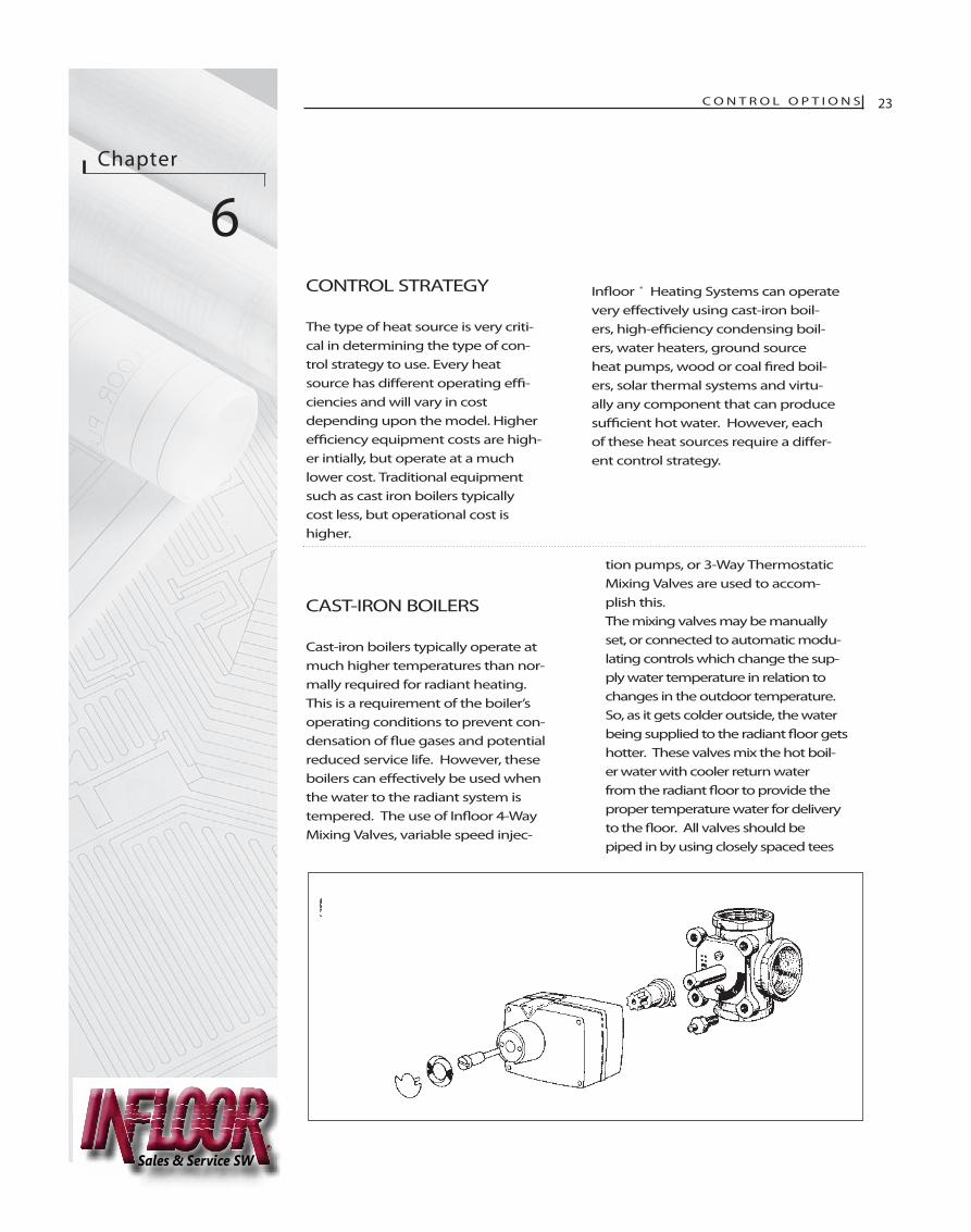
CAST-IRON BOILERS
Cast-iron boilers typically operate atmuch higher temperatures than nor-mally required for radiant heating.This is a requirement of the boiler’soperating conditions to prevent con-densation of �ue gases and potentialreduced service life. However, theseboilers can e�ectively be used whenthe water to the radiant system istempered. The use of In�oor 4-WayMixing Valves, variable speed injec-
tion pumps, or 3-Way ThermostaticMixing Valves are used to accom-plish this.The mixing valves may be manuallyset, or connected to automatic modu-lating controls which change the sup-ply water temperature in relation tochanges in the outdoor temperature.So, as it gets colder outside, the waterbeing supplied to the radiant �oor getshotter. These valves mix the hot boil-er water with cooler return waterfrom the radiant �oor to provide theproper temperature water for deliveryto the �oor. All valves should bepiped in by using closely spaced tees
In�oor ® Heating Systems can operatevery e�ectively using cast-iron boil-ers, high-e�ciency condensing boil-ers, water heaters, ground sourceheat pumps, wood or coal �red boil-ers, solar thermal systems and virtu-ally any component that can producesu�cient hot water. However, eachof these heat sources require a di�er-ent control strategy.
C O N T R O L O P T I O N S
Sales & Service SW
24 C O N T R O L O P T I O N SChapter 6
Mixing valves are primarily used to modu-late the water temperatures required by thedi�erent installation methods used in thesystem. However, sub-zones may be furthermodulated by using a 3-way thermostaticmixing valve.
Injection pumps are controlled by a resetcontroller that varies the speed of the pumpwhich provides necessary hot water to thesecondary loop to maintain the desired delivery water temperature. The reset control adjusts the secondary loop water temperature in relation to changes in theoutdoor temperature. Boiler return tempera-ture sensing and control is also available.
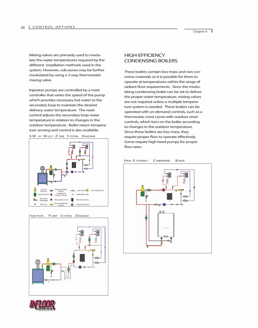
HIGH-EFFICIENCYCONDENSING BOILERS
These boilers contain low mass and non-cor-rosive materials so it is possible for them tooperate at temperatures within the range ofradiant �oor requirements. Since the modu-lating condensing boiler can be set to deliverthe proper water temperature, mixing valvesare not required unless a multiple tempera-ture system is needed. These boilers can beoperated with on-demand controls, such as athermostat, most come with outdoor resetcontrols, which turn on the boiler accordingto changes in the outdoor temperature.Since these boilers are low mass, theyrequire proper �ow to operate e�ectively.Some require high head pumps for proper�ow rates.
HIGH -E FFICIENCY C ONDENSING BOILER
3-W AY M ULTI -Z ONE S YSTEM DIAGRAM
I NJECTION P UMP S YSTEM DIAGRAM
Sales & Service SW
C O N T R O L O P T I O N SChapter 6
25
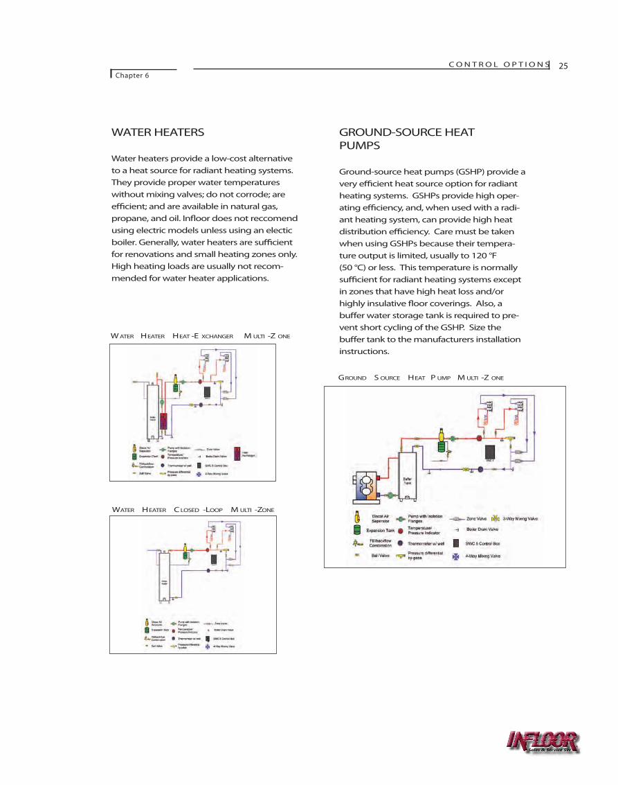
WATER HEATERS
Water heaters provide a low-cost alternativeto a heat source for radiant heating systems.They provide proper water temperatureswithout mixing valves; do not corrode; aree�cient; and are available in natural gas,propane, and oil. In�oor does not reccomendusing electric models unless using an electicboiler. Generally, water heaters are su�cientfor renovations and small heating zones only.High heating loads are usually not recom-mended for water heater applications.
GROUND-SOURCE HEATPUMPS
Ground-source heat pumps (GSHP) provide avery e�cient heat source option for radiantheating systems. GSHPs provide high oper-ating e�ciency, and, when used with a radi-ant heating system, can provide high heatdistribution e�ciency. Care must be takenwhen using GSHPs because their tempera-ture output is limited, usually to 120 °F (50 °C) or less. This temperature is normallysu�cient for radiant heating systems exceptin zones that have high heat loss and/orhighly insulative �oor coverings. Also, abu�er water storage tank is required to pre-vent short cycling of the GSHP. Size thebu�er tank to the manufacturers installationinstructions.
GROUND S OURCE HEAT P UMP M ULTI -Z ONE
WATER HEATER C LOSED -LOOP M ULTI -ZONE
W ATER HEATER HEAT -E XCHANGER M ULTI -Z ONE
Sales & Service SW
26 C O N T R O L O P T I O N SChapter 6
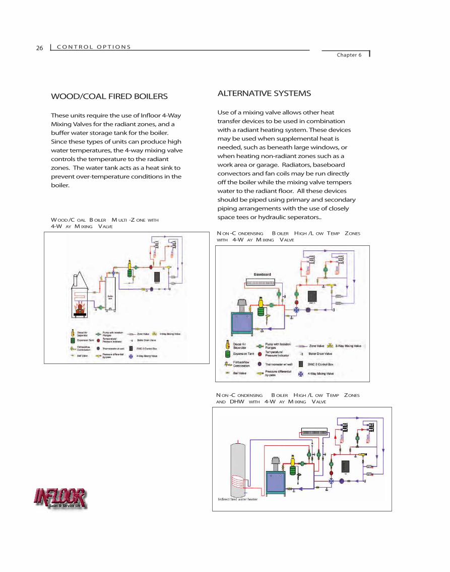
WOOD/COAL FIRED BOILERS
These units require the use of In�oor 4-WayMixing Valves for the radiant zones, and abu�er water storage tank for the boiler.Since these types of units can produce highwater temperatures, the 4-way mixing valvecontrols the temperature to the radiantzones. The water tank acts as a heat sink toprevent over-temperature conditions in theboiler.
ALTERNATIVE SYSTEMS
Use of a mixing valve allows other heattransfer devices to be used in combinationwith a radiant heating system. These devicesmay be used when supplemental heat isneeded, such as beneath large windows, orwhen heating non-radiant zones such as awork area or garage. Radiators, baseboardconvectors and fan coils may be run directlyo� the boiler while the mixing valve temperswater to the radiant �oor. All these devicesshould be piped using primary and secondarypiping arrangements with the use of closelyspace tees or hydraulic seperators..
N ON -C ONDENSING B OILER HIGH /L OW TEMP ZONES
WITH 4-W AY M IXING VALVE
N ON -C ONDENSING B OILER HIGH /L OW TEMP ZONES
AND DHW WITH 4-W AY M IXING VALVE
W OOD /C OAL B OILER M ULTI -Z ONE WITH
4-W AY M IXING VALVE
Sales & Service SW

C O N T R O L O P T I O N SChapter 6
27
SOLAR GAIN
In zones with a large amount of solar gain,there is a tendency for the radiant mass todischarge its heat during the day and then beslow to respond when the sun sets. To helpcounter this problem, use an In�oor dual-sensing thermostat (#29002). Set the dual- sensing remote sensor to maintain amass temperature lower than that requiredfor heating. The air sensor will control therequired zone temperature. This will pre-vent the mass from totally discharging itsheat and reduce the time required to heat up again.
While this control strategy will not preventtemperature overshoot due to a suddenin�ux of solar energy, it will help to acceler-ate the recovery of the thermal mass andlessen the lag time.
ZONING
Zoning the radiant system may be a desiredoption. Valves may be used to provide roomor area “sub-zoning.” Zone valves are usedto control the entire manifold assembly.This allows for zoning by room usage, �oorcoverings, �oor levels, etc. Individual loopcontrol can be achieved by using brass mani-folds and thermal actucators. This is a com-mon practice when reducing manifold loca-tions and using larger manifolds. Radiantheating systems provide very stable tempera-ture environments and over-zoning producesadded expense with minimal energy savings.
When using zone valves, match the thermo-stat anticipator with the valve manufactur-er’s instructions. Then adjust for longer orshorter operation to achieve desired boilercycling.
When used with a boiler, always incorporatea mixing valve device such as a 4-way mix-ing valve, a pressure di�erential bypass valve,or use bypass piping to assure proper �owthrough the boiler.
DUAL -S ENSING THERMOSTAT (#29002)
Sales & Service SW
Chapter
7ELECTRIC CONTROL BOX
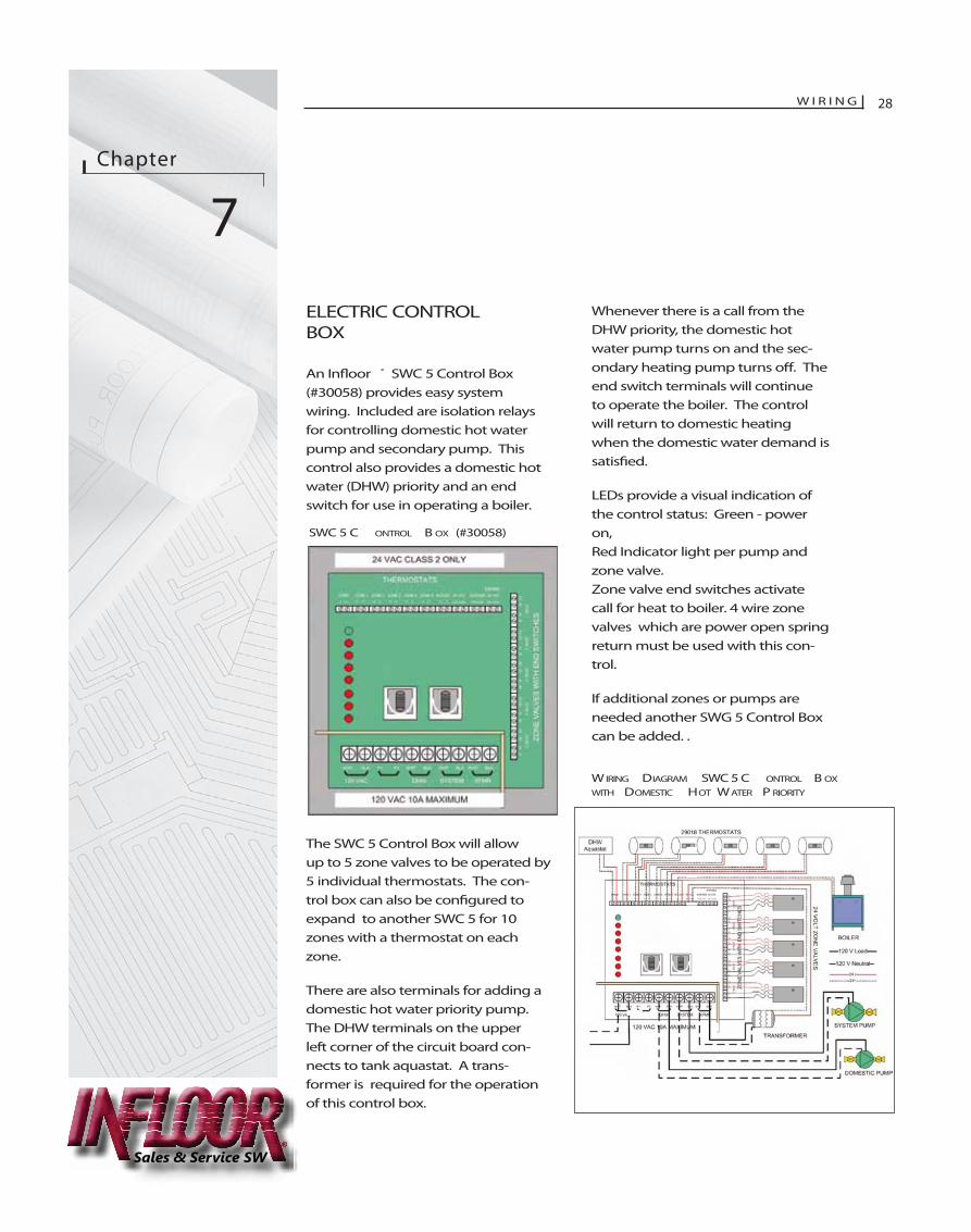
An In�oor ® SWC 5 Control Box(#30058) provides easy systemwiring. Included are isolation relaysfor controlling domestic hot waterpump and secondary pump. Thiscontrol also provides a domestic hotwater (DHW) priority and an endswitch for use in operating a boiler.
The SWC 5 Control Box will allowup to 5 zone valves to be operated by5 individual thermostats. The con-trol box can also be con�gured toexpand to another SWC 5 for 10zones with a thermostat on eachzone.
There are also terminals for adding adomestic hot water priority pump.The DHW terminals on the upperleft corner of the circuit board con-nects to tank aquastat. A trans-former is required for the operationof this control box.
Whenever there is a call from theDHW priority, the domestic hotwater pump turns on and the sec-ondary heating pump turns o�. Theend switch terminals will continueto operate the boiler. The controlwill return to domestic heatingwhen the domestic water demand issatis�ed.
LEDs provide a visual indication ofthe control status: Green - poweron,Red Indicator light per pump andzone valve. Zone valve end switches activatecall for heat to boiler. 4 wire zonevalves which are power open springreturn must be used with this con-trol.
If additional zones or pumps areneeded another SWG 5 Control Boxcan be added. .
W IRING DIAGRAM SWC 5 C ONTROL B OX
WITH DOMESTIC HOT WATER P RIORITY
SWC 5 C ONTROL B OX (#30058)
W I R I N G 28
Sales & Service SW
W I R I N GChapter 7
29
WIRING OPTIONS
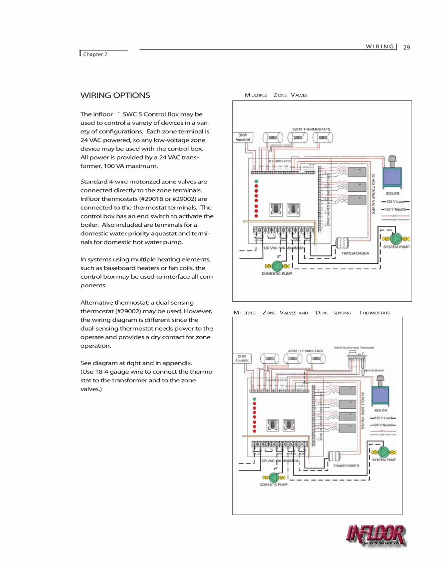
The In�oor ® SWC 5 Control Box may beused to control a variety of devices in a vari-ety of con�gurations. Each zone terminal is24 VAC powered, so any low-voltage zonedevice may be used with the control box.All power is provided by a 24 VAC trans-former, 100 VA maximum.
Standard 4-wire motorized zone valves areconnected directly to the zone terminals.In�oor thermostats (#29018 or #29002) areconnected to the thermostat terminals. Thecontrol box has an end switch to activate theboiler. Also included are terminals for adomestic water priority aquastat and termi-nals for domestic hot water pump.
In systems using multiple heating elements,such as baseboard heaters or fan coils, thecontrol box may be used to interface all com-ponents.
Alternative thermostat: a dual-sensing thermostat (#29002) may be used. However,the wiring diagram is di�erent since thedual-sensing thermostat needs power to theoperate and provides a dry contact for zoneoperation.
See diagram at right and in appendix.(Use 18-4 gauge wire to connect the thermo-stat to the transformer and to the zonevalves.)
M ULTIPLE ZONE VALVES
M ULTIPLE ZONE VALVES AND DUAL - SENSING THERMOSTATS
Sales & Service SW
30 W I R I N GChapter 7
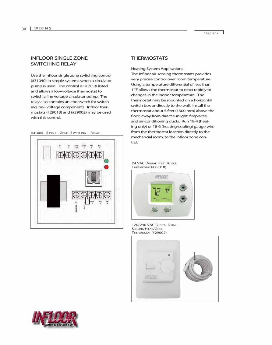
INFLOOR SINGLE ZONE SWITCHING RELAY
Use the In�oor single zone switching control(#31040) in simple systems when a circulatorpump is used. The control is UL/CSA listedand allows a low-voltage thermostat toswitch a line voltage circulator pump. Therelay also contains an end switch for switch-ing low- voltage components. In�oor ther-mostats (#29018) and (#29002) may be used with this control.
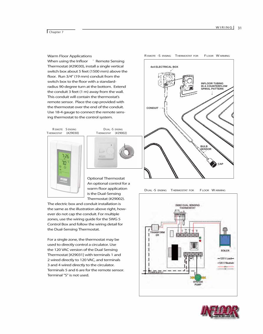
THERMOSTATS
Heating System ApplicationsThe In�oor air-sensing thermostats providesvery precise control over room temperature.Using a temperature di�erential of less than1 °F allows the thermostat to react rapidly tochanges in the indoor temperature. Thethermostat may be mounted on a horizontalswitch box or directly to the wall. Install thethermostat about 5 feet (1500 mm) above the�oor, away from direct sunlight, �replaces,and air-conditioning ducts. Run 18-4 (heat-ing only) or 18-6 (heating/cooling) gauge wirefrom the thermostat location directly to themechancial room, to the In�oor zone con-trol.
I NFLOOR S INGLE ZONE S WITCHING R ELAY
24 VAC DIGITAL H EAT /COOL
THERMOSTAT(#29018)
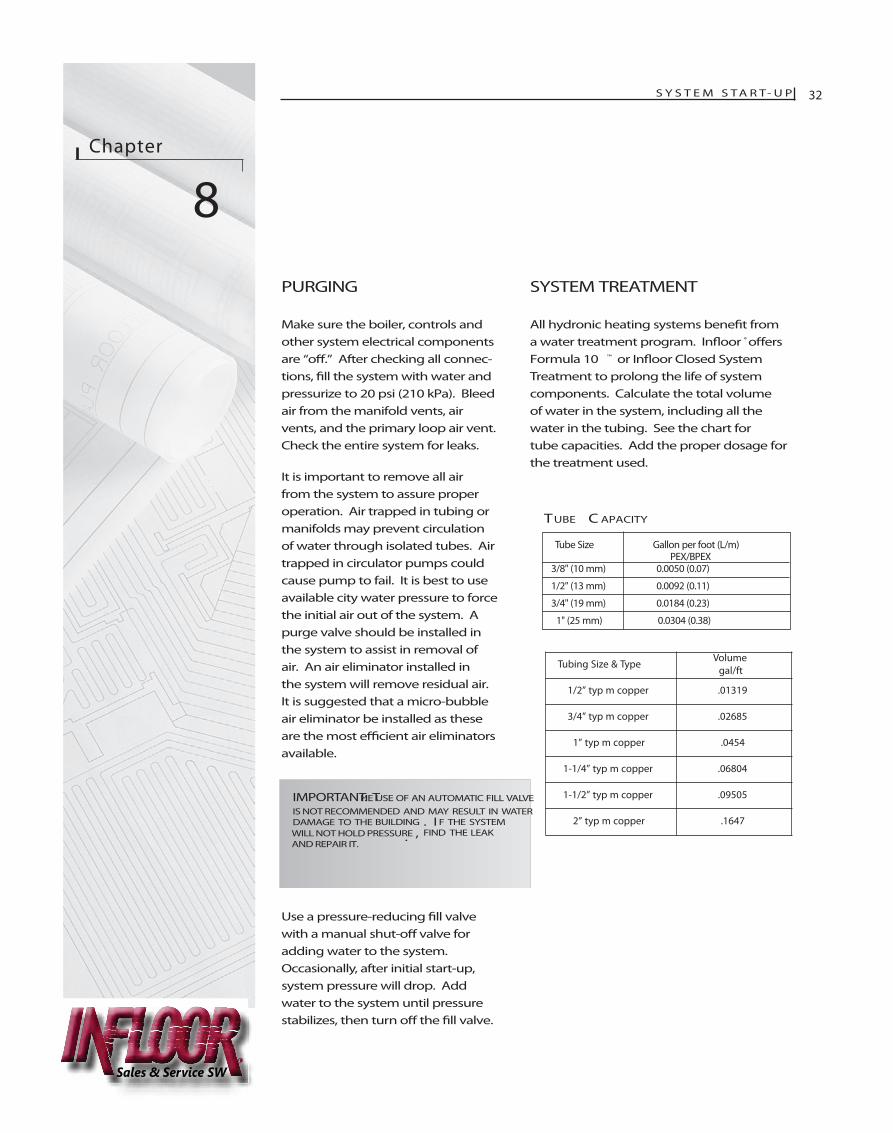
120/240 VAC DIGITAL DUAL -SENSING H EAT/COOL
THERMOSTAT (#29002)
Sales & Service SW
W I R I N GChapter 7
31
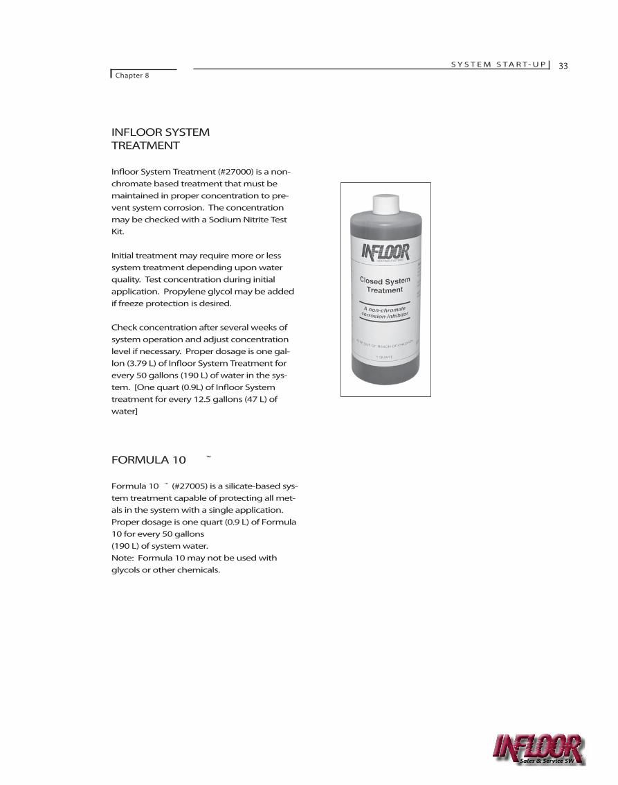
Warm Floor ApplicationsWhen using the In�oor ® Remote SensingThermostat (#29030), install a single verticalswitch box about 5 feet (1500 mm) above the�oor. Run 3/4" (19 mm) conduit from theswitch box to the �oor with a standard-radius 90-degree turn at the bottom. Extendthe conduit 3 feet (1 m) away from the wall.This conduit will contain the thermostat’sremote sensor. Place the cap provided withthe thermostat over the end of the conduit.Use 18-4 gauge to connect the remote sens-ing thermostat to the control system.
Optional ThermostatAn optional control for awarm �oor applicationis the Dual-SensingThermostat (#29002).
The electric box and conduit installation isthe same as the illustration above right, how-ever do not cap the conduit. For multiplezones, use the wiring guide for the SWG 5Control Box and follow the wiring detail forthe Dual-Sensing Thermostat.
For a single zone, the thermostat may beused to directly control a circulator. Use the 120 VAC version of the Dual SensingThermostat [#29031] with terminals 1 and 2 wired directly to 120 VAC, and terminals 3 and 4 wired directly to the circulator.Terminals 5 and 6 are for the remote sensor.Terminal "S" is not used.
R EMOTE -S ENSING THERMOSTAT FOR FLOOR W ARMING
4x4 ELECTRICAL BOX
CONDUIT
BULB SENSOR
CAP
INFLOOR TUBING IN A COUNTERFLOW SPIRAL PATTERN
R EMOTE S ENSING
THERMOSTAT (#29030)DUAL -S ENSING
THERMOSTAT (#29002)
DUAL -S ENSING THERMOSTAT FOR FLOOR W ARMING
Sales & Service SW
Chapter
8PURGING
Make sure the boiler, controls andother system electrical componentsare “o�.” After checking all connec-tions, �ll the system with water andpressurize to 20 psi (210 kPa). Bleedair from the manifold vents, airvents, and the primary loop air vent.Check the entire system for leaks.
It is important to remove all airfrom the system to assure properoperation. Air trapped in tubing ormanifolds may prevent circulationof water through isolated tubes. Airtrapped in circulator pumps couldcause pump to fail. It is best to useavailable city water pressure to forcethe initial air out of the system. Apurge valve should be installed inthe system to assist in removal ofair. An air eliminator installed inthe system will remove residual air.It is suggested that a micro-bubbleair eliminator be installed as theseare the most e�cient air eliminatorsavailable.
Use a pressure-reducing �ll valvewith a manual shut-o� valve foradding water to the system.Occasionally, after initial start-up,system pressure will drop. Addwater to the system until pressurestabilizes, then turn o� the �ll valve.
SYSTEM TREATMENT
All hydronic heating systems bene�t froma water treatment program. In�oor ® o�ersFormula 10 ™ or In�oor Closed SystemTreatment to prolong the life of systemcomponents. Calculate the total volumeof water in the system, including all thewater in the tubing. See the chart fortube capacities. Add the proper dosage forthe treatment used.
IMPORTANT: THE USE OF AN AUTOMATIC FILL VALVEIS NOT RECOMMENDED AND MAY RESULT IN WATERDAMAGE TO THE BUILDING . I F THE SYSTEM
, FIND THE LEAK.
S Y S T E M S TA R T- U P 32
Tube Size Gallon per foot (L/m)PEX/BPEX
3/8" (10 mm) 0.0050 (0.07)
1/2" (13 mm) 0.0092 (0.11)
3/4" (19 mm) 0.0184 (0.23)
1" (25 mm) 0.0304 (0.38)
TUBE C APACITY
Tubing Size & Type Volumegal/ft
1/2” typ m copper .01319
3/4” typ m copper .02685
1” typ m copper .0454
1-1/4” typ m copper .06804
1-1/2” typ m copper .09505
2” typ m copper .1647 WILL NOT HOLD PRESSUREAND REPAIR IT.
Sales & Service SW
S Y S T E M S TA R T- U PChapter 8
33
INFLOOR SYSTEMTREATMENT
In�oor System Treatment (#27000) is a non-chromate based treatment that must bemaintained in proper concentration to pre-vent system corrosion. The concentrationmay be checked with a Sodium Nitrite TestKit.
Initial treatment may require more or lesssystem treatment depending upon waterquality. Test concentration during initialapplication. Propylene glycol may be addedif freeze protection is desired.
Check concentration after several weeks ofsystem operation and adjust concentrationlevel if necessary. Proper dosage is one gal-lon (3.79 L) of In�oor System Treatment forevery 50 gallons (190 L) of water in the sys-tem. [One quart (0.9L) of In�oor Systemtreatment for every 12.5 gallons (47 L) ofwater]
FORMULA 10 ™
Formula 10 ™ (#27005) is a silicate-based sys-tem treatment capable of protecting all met-als in the system with a single application.Proper dosage is one quart (0.9 L) of Formula10 for every 50 gallons (190 L) of system water. Note: Formula 10 may not be used withglycols or other chemicals.
Sales & Service SW
Chapter
9THERMAL MASS
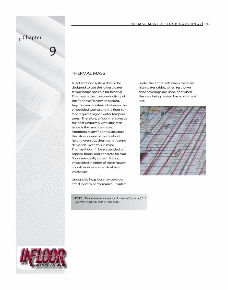
A radiant �oor system should bedesigned to use the lowest watertemperature possible for heating.This means that the conductivity ofthe �oor itself is very important.Any thermal resistance between theembedded tubing and the �oor sur-face requires higher water tempera-tures. Therefore, a �oor that spreadsthe heat uniformly with little resis-tance is the most desirable.Additionally, any �ooring structurethat stores some of the heat willhelp to even out short term heatingdemands. With this in mind,Therma-Floor ® for suspended orcapped �oors, and concrete for slab�oors are ideally suited. Tubingembedded in either of these materi-als will work as an excellent heatexchanger.
Under-slab heat loss may severelya�ect system performance. Insulate
under the entire slab when there arehigh water tables, when restrictive�oor coverings are used, and whenthe area being heated has a high heatloss.
T H E R M A L M A S S & F L O O R C O V E R I N G S 34
NOTE: THE MINIMUM DEPTH OF THERMA-FLOOR IS3/4"(25 MM) OVER THE TOP OF THE TUBE.
Sales & Service SW
T H E R M A L M A S S & F L O O R C O V E R I N G SChapter 9
35
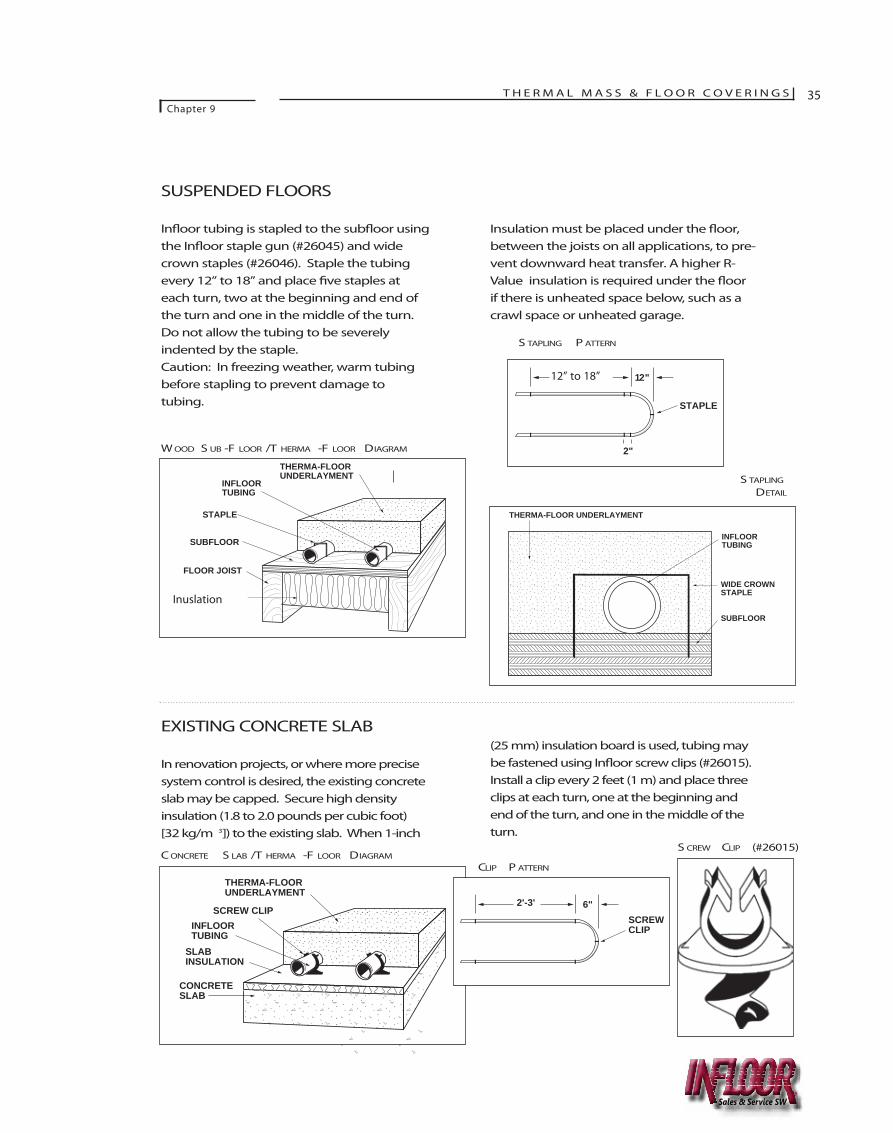
SUSPENDED FLOORS
In�oor tubing is stapled to the sub�oor usingthe In�oor staple gun (#26045) and widecrown staples (#26046). Staple the tubingevery 12” to 18” and place �ve staples ateach turn, two at the beginning and end ofthe turn and one in the middle of the turn.Do not allow the tubing to be severelyindented by the staple. Caution: In freezing weather, warm tubingbefore stapling to prevent damage to tubing.
Insulation must be placed under the �oor,between the joists on all applications, to pre-vent downward heat transfer. A higher R-Value insulation is required under the �oorif there is unheated space below, such as acrawl space or unheated garage.
62
THERMA-FLOOR UNDERLAYMENT
INFLOOR TUBING
INSULATION (OPTIONAL)
FLOOR JOIST
SUBFLOOR
STAPLE
64
THERMA-FLOOR UNDERLAYMENT
SLAB INSULATION
CONCRETE SLAB
SCREW CLIPINFLOOR TUBING
62.5
2-3' 12"
2"
STAPLE
64.5
2'-3' 6"SCREW CLIP
63
THERMA-FLOOR UNDERLAYMENT
WIDE CROWN STAPLE
SUBFLOOR
INFLOOR TUBING
EXISTING CONCRETE SLAB
In renovation projects, or where more precisesystem control is desired, the existing concreteslab may be capped. Secure high density insulation (1.8 to 2.0 pounds per cubic foot) [32 kg/m 3]) to the existing slab. When 1-inch
(25 mm) insulation board is used, tubing maybe fastened using In�oor screw clips (#26015).Install a clip every 2 feet (1 m) and place threeclips at each turn, one at the beginning andend of the turn, and one in the middle of theturn.
W OOD S UB -F LOOR /T HERMA -F LOOR DIAGRAM
S TAPLING P ATTERN
C ONCRETE S LAB /T HERMA -F LOOR DIAGRAMCLIP P ATTERN
S CREW CLIP (#26015)
S TAPLING
DETAIL
Inuslation
12” to 18”
Sales & Service SW
36 T H E R M A L M A S S & F L O O R C O V E R I N G SChapter 9
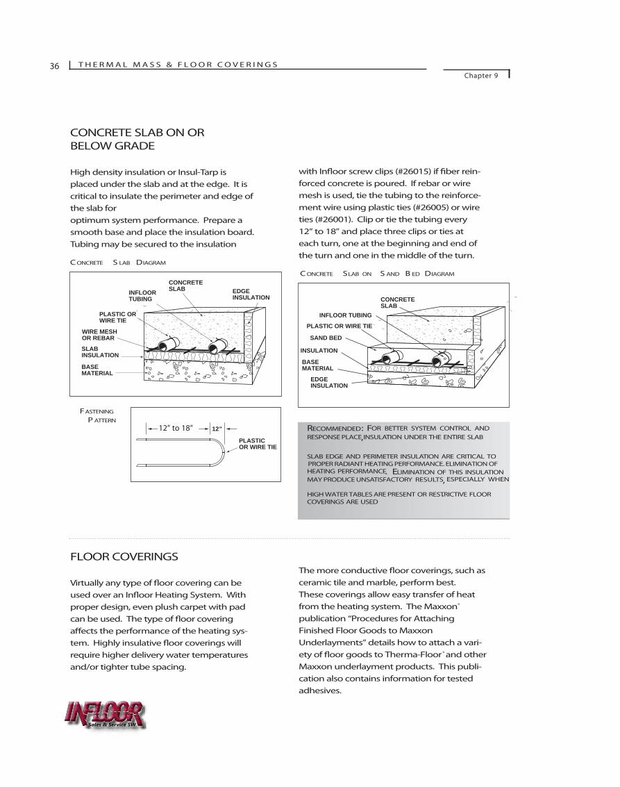
CONCRETE SLAB ON ORBELOW GRADE
High density insulation or Insul-Tarp isplaced under the slab and at the edge. It iscritical to insulate the perimeter and edge ofthe slab for optimum system performance. Prepare asmooth base and place the insulation board.Tubing may be secured to the insulation
with In�oor screw clips (#26015) if �ber rein-forced concrete is poured. If rebar or wiremesh is used, tie the tubing to the reinforce-ment wire using plastic ties (#26005) or wireties (#26001). Clip or tie the tubing every12” to 18” and place three clips or ties ateach turn, one at the beginning and end ofthe turn and one in the middle of the turn.66
CONCRETE SLAB EDGE
INSULATIONINFLOOR TUBING
SLAB INSULATION
BASE MATERIAL
WIRE MESH OR REBAR
PLASTIC OR WIRE TIE
66.5
4' 12"
PLASTIC OR WIRE TIE
67
INFLOOR TUBING
SAND BED
INSULATION
BASE MATERIAL
EDGE INSULATION
CONCRETE SLAB
PLASTIC OR WIRE TIE
RECOMMENDED: FOR BETTER SYSTEM CONTROL AND
, RESPONSE PLACE INSULATION UNDER THE ENTIRE SLAB
SLAB EDGE AND PERIMETER INSULATION ARE CRITICAL TO
HEATING PERFORMANCE. ELIMINATION OF THIS INSULATIONMAY PRODUCE UNSATISFACTORY RESULTS, ESPECIALLY WHEN
HIGH WATER TABLES ARE PRESENT OR RESTRICTIVE FLOORCOVERINGS ARE USED
.
FLOOR COVERINGS
Virtually any type of �oor covering can beused over an In�oor Heating System. Withproper design, even plush carpet with padcan be used. The type of �oor coveringa�ects the performance of the heating sys-tem. Highly insulative �oor coverings willrequire higher delivery water temperaturesand/or tighter tube spacing.
The more conductive �oor coverings, such asceramic tile and marble, perform best.These coverings allow easy transfer of heatfrom the heating system. The Maxxon®
publication “Procedures for AttachingFinished Floor Goods to MaxxonUnderlayments” details how to attach a vari-ety of �oor goods to Therma-Floor® and otherMaxxon underlayment products. This publi-cation also contains information for testedadhesives.
FASTENING
P ATTERN
C ONCRETE S LAB DIAGRAM
C ONCRETE SLAB ON S AND B ED DIAGRAM
12” to 18”
Sales & Service SW
PROPER RADIANT HEATING PERFORMANCE. ELIMINATION OF
T H E R M A L M A S S & F L O O R C O V E R I N G SChapter 9
37
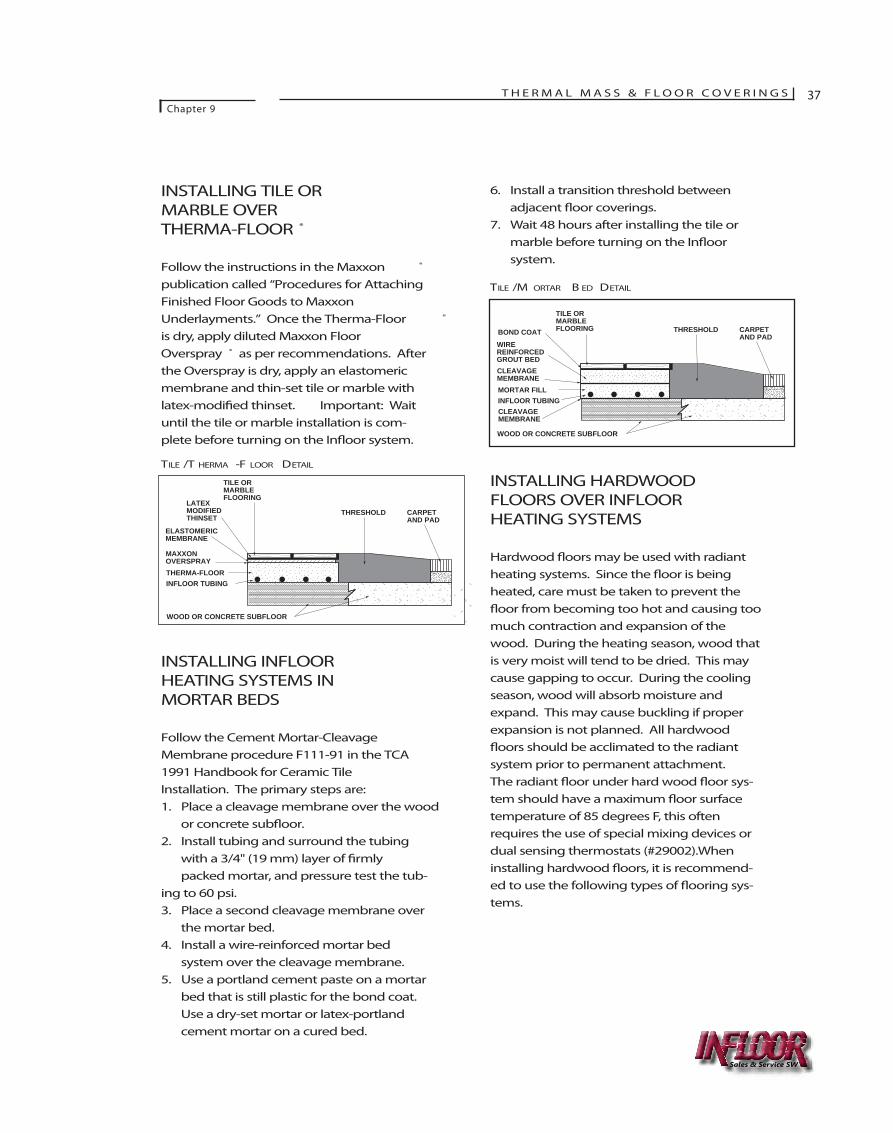
INSTALLING TILE ORMARBLE OVER THERMA-FLOOR ®
Follow the instructions in the Maxxon ®
publication called “Procedures for AttachingFinished Floor Goods to MaxxonUnderlayments.” Once the Therma-Floor ®
is dry, apply diluted Maxxon FloorOverspray ® as per recommendations. Afterthe Overspray is dry, apply an elastomericmembrane and thin-set tile or marble withlatex-modi�ed thinset. Important: Waituntil the tile or marble installation is com-plete before turning on the In�oor system.
INSTALLING INFLOORHEATING SYSTEMS INMORTAR BEDS
Follow the Cement Mortar-CleavageMembrane procedure F111-91 in the TCA1991 Handbook for Ceramic TileInstallation. The primary steps are:1. Place a cleavage membrane over the wood
or concrete sub�oor.2. Install tubing and surround the tubing
with a 3/4" (19 mm) layer of �rmly packed mortar, and pressure test the tub-
ing to 60 psi.3. Place a second cleavage membrane over
the mortar bed.4. Install a wire-reinforced mortar bed
system over the cleavage membrane.5. Use a portland cement paste on a mortar
bed that is still plastic for the bond coat. Use a dry-set mortar or latex-portland cement mortar on a cured bed.
6. Install a transition threshold between adjacent �oor coverings.
7. Wait 48 hours after installing the tile or marble before turning on the In�oor system.
INSTALLING HARDWOODFLOORS OVER INFLOORHEATING SYSTEMS
Hardwood �oors may be used with radiantheating systems. Since the �oor is beingheated, care must be taken to prevent the�oor from becoming too hot and causing toomuch contraction and expansion of thewood. During the heating season, wood thatis very moist will tend to be dried. This maycause gapping to occur. During the coolingseason, wood will absorb moisture andexpand. This may cause buckling if properexpansion is not planned. All hardwood�oors should be acclimated to the radiantsystem prior to permanent attachment.The radiant �oor under hard wood �oor sys-tem should have a maximum �oor surfacetemperature of 85 degrees F, this oftenrequires the use of special mixing devices ordual sensing thermostats (#29002).Wheninstalling hardwood �oors, it is recommend-ed to use the following types of �ooring sys-tems.
THRESHOLD CARPET AND PAD
WOOD OR CONCRETE SUBFLOOR
TILE OR MARBLE FLOORING
LATEX MODIFIED THINSET
ELASTOMERIC MEMBRANE
THERMA-FLOORINFLOOR TUBING
MAXXON OVERSPRAY
68
THRESHOLD CARPET AND PAD
WOOD OR CONCRETE SUBFLOOR
TILE OR MARBLE FLOORINGBOND COAT
WIRE REINFORCED GROUT BED
MORTAR FILLINFLOOR TUBING
CLEAVAGE MEMBRANE
CLEAVAGE MEMBRANE
69
TILE /T HERMA -F LOOR DETAIL
TILE /M ORTAR B ED DETAIL
Sales & Service SW
38 T H E R M A L M A S S & F L O O R C O V E R I N G SChapter 9
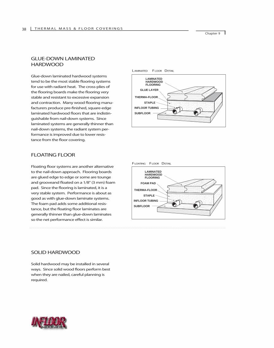
GLUE-DOWN LAMINATEDHARDWOOD
Glue-down laminated hardwood systemstend to be the most stable �ooring systemsfor use with radiant heat. The cross-plies ofthe �ooring boards make the �ooring verystable and resistant to excessive expansionand contraction. Many wood �ooring manu-facturers produce pre-�nished, square-edgelaminated hardwood �oors that are indistin-guishable from nail-down systems. Sincelaminated systems are generally thinner thannail-down systems, the radiant system per-formance is improved due to lower resis-tance from the �oor covering.
FLOATING FLOOR
Floating �oor systems are another alternativeto the nail-down approach. Flooring boardsare glued edge to edge or some are toungeand grooveand �oated on a 1/8" (3 mm) foampad. Since the �ooring is laminated, it is avery stable system. Performance is about asgood as with glue-down laminate systems.The foam pad adds some additional resis-tance, but the �oating �oor laminates aregenerally thinner than glue-down laminatesso the net performance e�ect is similar.
SOLID HARDWOOD
Solid hardwood may be installed in severalways. Since solid wood �oors perform bestwhen they are nailed, careful planning isrequired.
70
INFLOOR TUBING
GLUE LAYER
SUBFLOOR
LAMINATED HARDWOOD FLOORING
THERMA-FLOOR
STAPLE
8
71
INFLOOR TUBING
FOAM PAD
SUBFLOOR
LAMINATED HARDWOOD FLOORING
THERMA-FLOOR
STAPLE
LAMINATED FLOOR DETAIL
FLOATING FLOOR DETAIL
Sales & Service SW
T H E R M A L M A S S & F L O O R C O V E R I N G SChapter 9
39
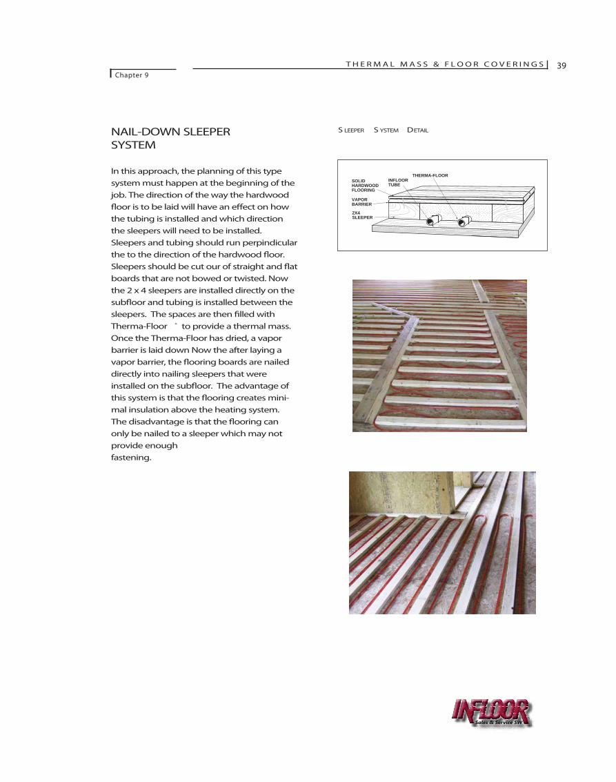
NAIL-DOWN SLEEPERSYSTEM
In this approach, the planning of this typesystem must happen at the beginning of thejob. The direction of the way the hardwood�oor is to be laid will have an e�ect on howthe tubing is installed and which directionthe sleepers will need to be installed.Sleepers and tubing should run perpindicularthe to the direction of the hardwood �oor.Sleepers should be cut our of straight and �atboards that are not bowed or twisted. Nowthe 2 x 4 sleepers are installed directly on thesub�oor and tubing is installed between thesleepers. The spaces are then �lled withTherma-Floor ® to provide a thermal mass.Once the Therma-Floor has dried, a vaporbarrier is laid down Now the after laying avapor barrier, the �ooring boards are naileddirectly into nailing sleepers that wereinstalled on the sub�oor. The advantage ofthis system is that the �ooring creates mini-mal insulation above the heating system.The disadvantage is that the �ooring canonly be nailed to a sleeper which may notprovide enough fastening.
SOLID HARDWOOD FLOORING
VAPOR BARRIER
INFLOOR TUBE
THERMA-FLOOR
2X4 SLEEPER
S LEEPER S YSTEM DETAIL
Sales & Service SW
T H E R M A L M A S S & F L O O R C O V E R I N G SChapter 9
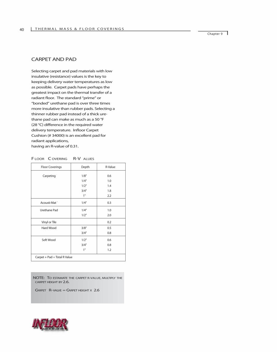
CARPET AND PAD
Selecting carpet and pad materials with lowinsulative (resistance) values is the key tokeeping delivery water temperatures as lowas possible. Carpet pads have perhaps thegreatest impact on the thermal transfer of aradiant �oor. The standard “prime” or“bonded” urethane pad is over three timesmore insulative than rubber pads. Selecting athinner rubber pad instead of a thick ure-thane pad can make as much as a 50 °F (28 °C) di�erence in the required water delivery temperature. In�oor CarpetCushion (# 34000) is an excellent pad forradiant applications, having an R-value of 0.31.
Floor Coverings Depth R-Value
Carpeting 1/8" 0.61/4" 1.01/2" 1.43/4" 1.8
1" 2.2
Acousti-Mat ® 1/4" 0.3
Urethane Pad 1/4" 1.01/2" 2.0
Vinyl or Tile 0.2
Hard Wood 3/8" 0.53/4" 0.8
Soft Wood 1/2" 0.63/4" 0.8
1" 1.2
Carpet + Pad = Total R Value
F LOOR C OVERING R-V ALUES
NOTE: TO ESTAMATE THE CARPET R-VALUE, MULTIPLY THECARPET HEIGHT BY 2.6.
CARPET R-VALVE = CARPET HEIGHT X 2.6
40
Sales & Service SW
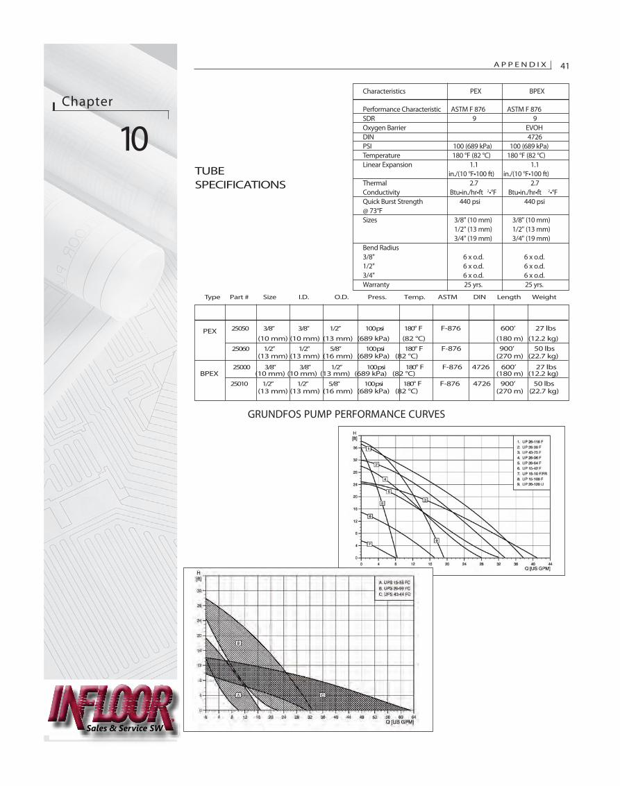
TUBESPECIFICATIONS
Chapter
10
A P P E N D I X 41
Characteristics PEX BPEX
Performance Characteristic ASTM F 876 ASTM F 876SDR 9 9Oxygen Barrier EVOHDIN 4726PSI 100 (689 kPa) 100 (689 kPa)Temperature 180 °F (82 °C) 180 °F (82 °C)Linear Expansion 1.1 1.1
in./(10 °F•100 ft) in./(10 °F•100 ft)Thermal 2.7 2.7Conductivity Btu•in./hr•ft 2•°F Btu•in./hr•ft 2•°FQuick Burst Strength 440 psi 440 psi@ 73°FSizes 3/8" (10 mm) 3/8" (10 mm)
1/2" (13 mm) 1/2" (13 mm)3/4" (19 mm) 3/4" (19 mm)
Bend Radius3/8" 6 x o.d. 6 x o.d.1/2" 6 x o.d. 6 x o.d.3/4" 6 x o.d. 6 x o.d.Warranty 25 yrs. 25 yrs.
PEX(10 mm) (10 mm) (13 mm) (689 kPa) (82 °C) (180 m) (12.2 kg)
(13 mm) (13 mm) (16 mm) (689 kPa) (82 °C) (270 m) (22.7 kg)
BPEX (10 mm) (10 mm) (13 mm) (689 kPa) (82 °C) (180 m) (12.2 kg)
(13 mm) (13 mm) (16 mm) (689 kPa) (82 °C) (270 m) (22.7 kg)
GRUNDFOS PUMP PERFORMANCE CURVES
Sales & Service SW
Type Part # Size I.D. O.D. Press. Temp. ASTM DIN Length Weight
25050 3/8” 3/8” 1/2” 100 psi 180° F F-876 600’ 27 lbs
25060 1/2” 1/2” 5/8” 100 psi 180° F F-876 900’ 50 lbs
25000 3/8” 3/8” 1/2” 100 psi 180° F F-876 4726 600’ 27 lbs
25010 1/2” 1/2” 5/8” 100 psi 180° F F-876 4726 900’ 50 lbs
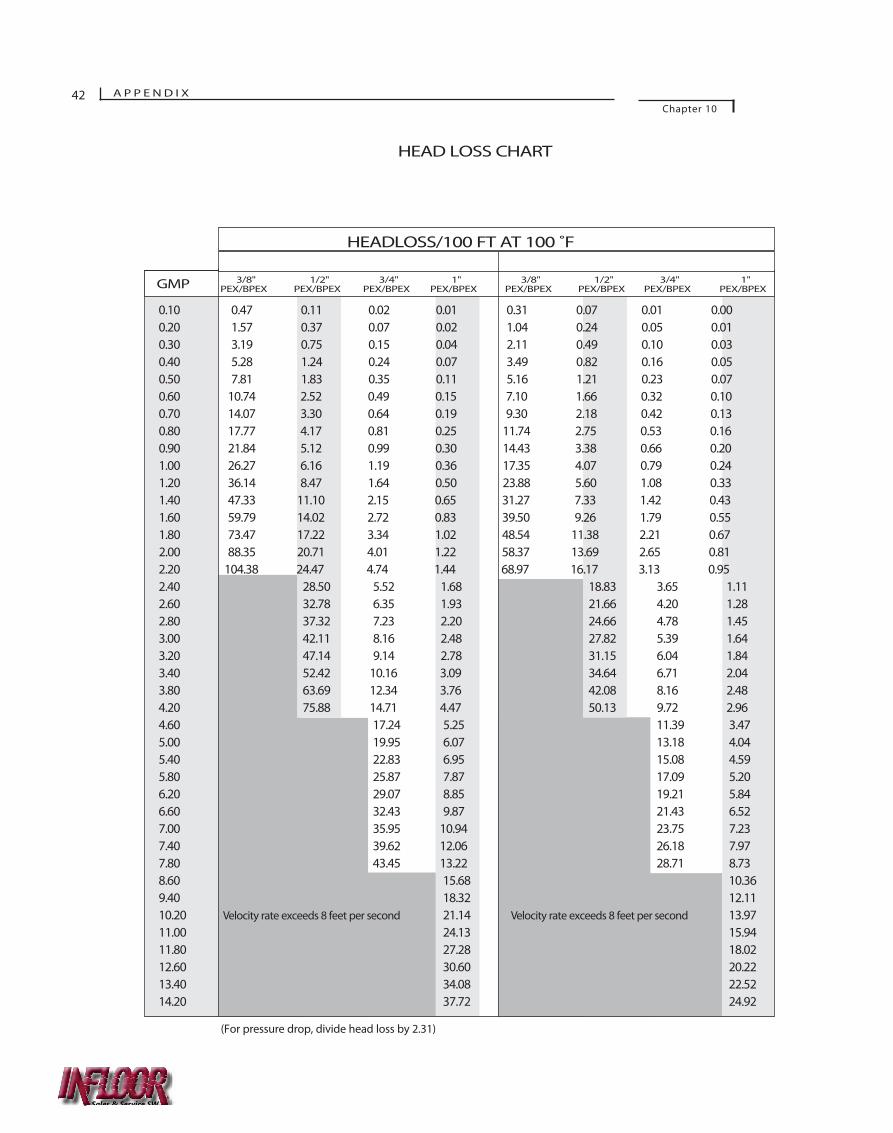
0.10 0.47 0.11 0.02 0.01 0.31 0.07 0.01 0.000.20 1.57 0.37 0.07 0.02 1.04 0.24 0.05 0.010.30 3.19 0.75 0.15 0.04 2.11 0.49 0.10 0.030.40 5.28 1.24 0.24 0.07 3.49 0.82 0.16 0.050.50 7.81 1.83 0.35 0.11 5.16 1.21 0.23 0.070.60 10.74 2.52 0.49 0.15 7.10 1.66 0.32 0.100.70 14.07 3.30 0.64 0.19 9.30 2.18 0.42 0.130.80 17.77 4.17 0.81 0.25 11.74 2.75 0.53 0.160.90 21.84 5.12 0.99 0.30 14.43 3.38 0.66 0.201.00 26.27 6.16 1.19 0.36 17.35 4.07 0.79 0.241.20 36.14 8.47 1.64 0.50 23.88 5.60 1.08 0.331.40 47.33 11.10 2.15 0.65 31.27 7.33 1.42 0.431.60 59.79 14.02 2.72 0.83 39.50 9.26 1.79 0.551.80 73.47 17.22 3.34 1.02 48.54 11.38 2.21 0.672.00 88.35 20.71 4.01 1.22 58.37 13.69 2.65 0.812.20 104.38 24.47 4.74 1.44 68.97 16.17 3.13 0.952.40 28.50 5.52 1.68 18.83 3.65 1.112.60 32.78 6.35 1.93 21.66 4.20 1.282.80 37.32 7.23 2.20 24.66 4.78 1.453.00 42.11 8.16 2.48 27.82 5.39 1.643.20 47.14 9.14 2.78 31.15 6.04 1.843.40 52.42 10.16 3.09 34.64 6.71 2.043.80 63.69 12.34 3.76 42.08 8.16 2.484.20 75.88 14.71 4.47 50.13 9.72 2.964.60 17.24 5.25 11.39 3.475.00 19.95 6.07 13.18 4.045.40 22.83 6.95 15.08 4.595.80 25.87 7.87 17.09 5.206.20 29.07 8.85 19.21 5.846.60 32.43 9.87 21.43 6.527.00 35.95 10.94 23.75 7.237.40 39.62 12.06 26.18 7.977.80 43.45 13.22 28.71 8.738.60 15.68 10.369.40 18.32 12.1110.20 Velocity rate exceeds 8 feet per second 21.14 Velocity rate exceeds 8 feet per second 13.9711.00 24.13 15.9411.80 27.28 18.0212.60 30.60 20.2213.40 34.08 22.5214.20 37.72 24.92
HEAD LOSS CHART
HEADLOSS/100 FT AT 100 ˚F
GMP 3/8"PEX/BPEX
1/2"PEX/BPEX
3/4"PEX/BPEX
1"PEX/BPEX
3/8"PEX/BPEX
1/2"PEX/BPEX
3/4"PEX/BPEX
1"PEX/BPEX
42 A P P E N D I XChapter 10
(For pressure drop, divide head loss by 2.31)
Sales & Service SW
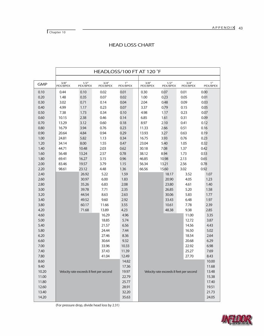
A P P E N D I XChapter 10
43
0.10 0.44 0.10 0.02 0.01 0.30 0.07 0.01 0.000.20 1.48 0.35 0.07 0.02 1.00 0.23 0.05 0.010.30 3.02 0.71 0.14 0.04 2.04 0.48 0.09 0.030.40 4.99 1.17 0.23 0.07 3.37 0.79 0.15 0.050.50 7.38 1.73 0.34 0.10 4.98 1.17 0.23 0.070.60 10.15 2.38 0.46 0.14 6.85 1.61 0.31 0.090.70 13.29 3.12 0.60 0.18 8.97 2.10 0.41 0.120.80 16.79 3.94 0.76 0.23 11.33 2.66 0.51 0.160.90 20.64 4.84 0.94 0.29 13.93 3.27 0.63 0.191.00 24.81 5.82 1.13 0.34 16.75 3.93 0.76 0.231.20 34.14 8.00 1.55 0.47 23.04 5.40 1.05 0.321.40 44.71 10.48 2.03 0.62 30.18 7.08 1.37 0.421.60 56.48 13.24 2.57 0.78 38.12 8.94 1.73 0.531.80 69.41 16.27 3.15 0.96 46.85 10.98 2.13 0.652.00 83.46 19.57 3.79 1.15 56.34 13.21 2.56 0.782.20 98.61 23.12 4.48 1.36 66.56 15.60 3.02 0.922.40 26.92 5.22 1.59 18.17 3.52 1.072.60 30.97 6.00 1.83 20.90 4.05 1.232.80 35.26 6.83 2.08 23.80 4.61 1.403.00 39.78 7.71 2.35 26.85 5.20 1.583.20 44.54 8.63 2.63 30.06 5.83 1.773.40 49.52 9.60 2.92 33.43 6.48 1.973.80 60.17 11.66 3.55 10.61 7.78 2.394.20 71.68 13.89 4.23 48.38 9.38 2.854.60 16.29 4.96 11.00 3.355.00 18.85 5.74 12.72 3.875.40 21.57 6.56 14.56 4.435.80 24.44 7.44 16.50 5.026.20 27.46 8.36 18.54 2.646.60 30.64 9.32 20.68 6.297.00 33.96 10.33 22.92 6.987.40 37.43 11.39 25.27 7.697.80 41.04 12.49 27.70 8.438.60 14.82 10.009.40 17.36 11.6810.20 Velocity rate exceeds 8 feet per second 19.97 Velocity rate exceeds 8 feet per second 13.4811.00 22.79 15.3811.80 25.77 17.4012.60 28.91 19.5113.40 32.20 21.7314.20 35.63 24.05
HEAD LOSS CHART
HEADLOSS/100 FT AT 120 ˚F
GMP 3/8"PEX/BPEX
1/2"PEX/BPEX
3/4"PEX/BPEX
1"PEX/BPEX
3/8"PEX/BPEX
1/2"PEX/BPEX
3/4"PEX/BPEX
1"PEX/BPEX
(For pressure drop, divide head loss by 2.31)
Sales & Service SW
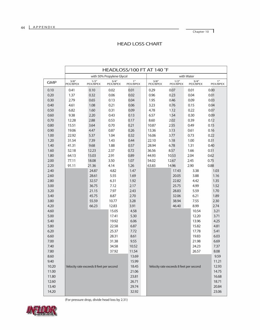
44 A P P E N D I XChapter 10
0.10 0.41 0.10 0.02 0.01 0.29 0.07 0.01 0.000.20 1.37 0.32 0.06 0.02 0.96 0.23 0.04 0.010.30 2.79 0.65 0.13 0.04 1.95 0.46 0.09 0.030.40 4.61 1.08 0.21 0.06 3.23 0.76 0.15 0.040.50 6.82 1.60 0.31 0.09 4.78 1.12 0.22 0.070.60 9.38 2.20 0.43 0.13 6.57 1.54 0.30 0.090.70 12.28 2.88 0.53 0.17 8.60 2.02 0.39 0.120.80 15.51 3.64 0.70 0.21 10.87 2.55 0.49 0.150.90 19.06 4.47 0.87 0.26 13.36 3.13 0.61 0.161.00 22.92 5.37 1.04 0.32 16.06 3.77 0.73 0.221.20 31.54 7.39 1.43 0.44 22.10 5.18 1.00 0.311.40 41.31 9.68 1.88 0.57 28.94 6.78 1.31 0.401.60 52.18 12.23 2.37 0.72 36.56 8.57 1.66 0.511.80 64.13 15.03 2.91 0.89 44.93 10.53 2.04 0.622.00 77.11 18.08 3.50 1.07 54.02 12.67 2.45 0.752.20 91.11 21.36 4.14 1.26 63.83 14.96 2.90 0.882.40 24.87 4.82 1.47 17.43 3.38 1.032.60 28.61 5.55 1.69 20.05 3.88 1.162.80 32.57 6.31 1.92 22.82 4.42 1.353.00 36.75 7.12 2.17 25.75 4.99 1.523.20 21.15 7.97 2.43 28.83 5.59 1.703.40 45.75 8.87 2.70 32.06 6.21 1.893.80 55.59 10.77 3.28 38.94 7.55 2.304.20 66.23 12.83 3.91 46.40 8.99 2.744.60 15.05 4.58 10.54 3.215.00 17.41 5.30 12.20 3.715.40 19.92 6.06 13.96 4.255.80 22.58 6.87 15.82 4.816.20 25.37 7.72 17.78 5.416.60 28.31 8.61 19.83 6.037.00 31.38 9.55 21.98 6.697.40 34.58 10.52 24.23 7.377.80 37.92 11.54 26.57 8.088.60 13.69 9.599.40 15.99 11.2110.20 Velocity rate exceeds 8 feet per second 18.45 Velocity rate exceeds 8 feet per second 12.9311.00 21.06 14.7511.80 23.81 16.6812.60 26.71 18.7113.40 29.74 20.8414.20 32.92 23.06
HEAD LOSS CHART
HEADLOSS/100 FT AT 140 ˚Fwith 50% Propylene Glycol with Water
GMP 3/8"PEX/BPEX
1/2"PEX/BPEX
3/4"PEX/BPEX
1"PEX/BPEX
3/8"PEX/BPEX
1/2"PEX/BPEX
3/4"PEX/BPEX
1"PEX/BPEX
(For pressure drop, divide head loss by 2.31)
Sales & Service SW
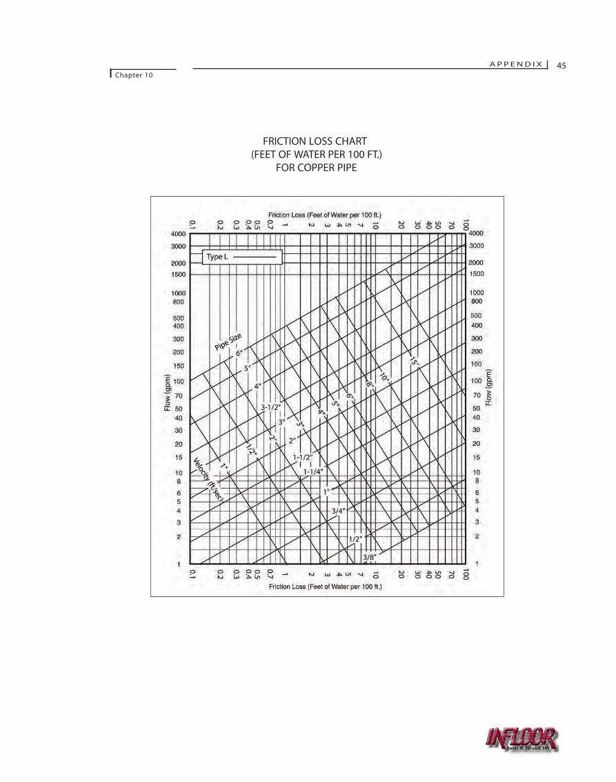
A P P E N D I XChapter 10
45
FRICTION LOSS CHART(FEET OF WATER PER 100 FT.)
FOR COPPER PIPE
Sales & Service SW

NON-CONDENSING BOILERMULTI-ZONE WITH 4-WAY MIXING VALVE
NOTE: THISDRAWING IS
ILLUSTRATIVE ONLY. SOME COMPONENTS HAVEBEEN OMITTED FOR CLARITY. COMPLY WITH
LOCAL CODES WHEN PIPING SYSTEMS.
46 A P P E N D I X
Chapter 10
residential guide revision 2:4715 Resdntl Guide 2/18/2008 4:07 PM Page 47
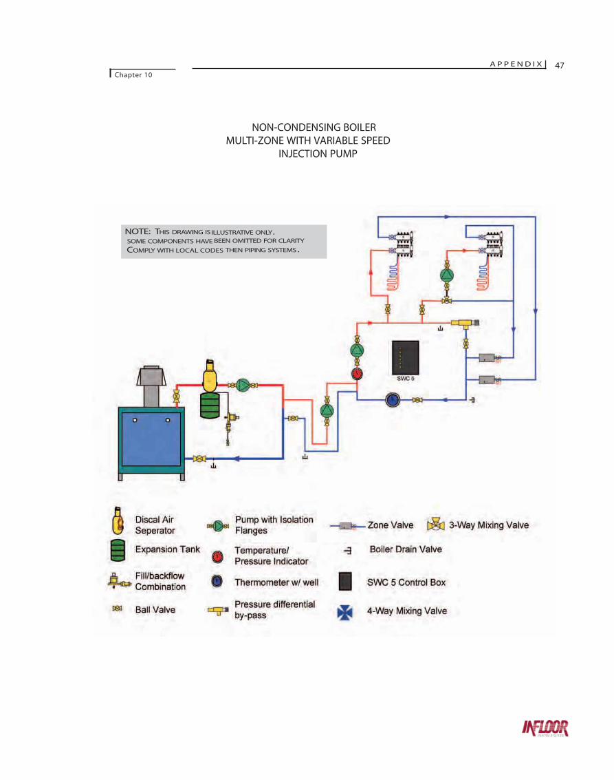
NON-CONDENSING BOILERMULTI-ZONE WITH VARIABLE SPEED
INJECTION PUMP
A P P E N D I XChapter 10
47
NOTE: THIS DRAWING ISILLUSTRATIVE ONLY. SOME COMPONENTS HAVE BEEN OMITTED FOR CLARITY
COMPLY WITH LOCAL CODES THEN PIPING SYSTEMS.

NON-CONDENSING BOILERMULTI-ZONE WITH 4-WAY MIXING VALVE
AND 3-WAY MIXING VALVE SUB-ZONE
48 A P P E N D I XChapter 10
NOTE: THISDRAWING ISILLUSTRATIVE ONLY. SOME COMPONENTS HAVEBEEN OMITTED FOR CLARITY. COMPLY WITHLOCAL CODES WHEN PIPING SYSTEMS.
Sales & Service SW
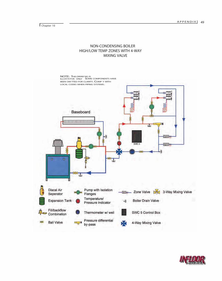
A P P E N D I XChapter 10
49
NON-CONDENSING BOILERHIGH/LOW TEMP ZONES WITH 4-WAY
MIXING VALVE
Sales & Service SW
NOTE: THIS DRAW NG ISILLUSTATIVE ONLY SOME COMPONENTS HAVE
BEEN OM TTED FOR CLARITY. COMP Y WITHLOCAL CODES WHEN PIPING SYSTEMS.
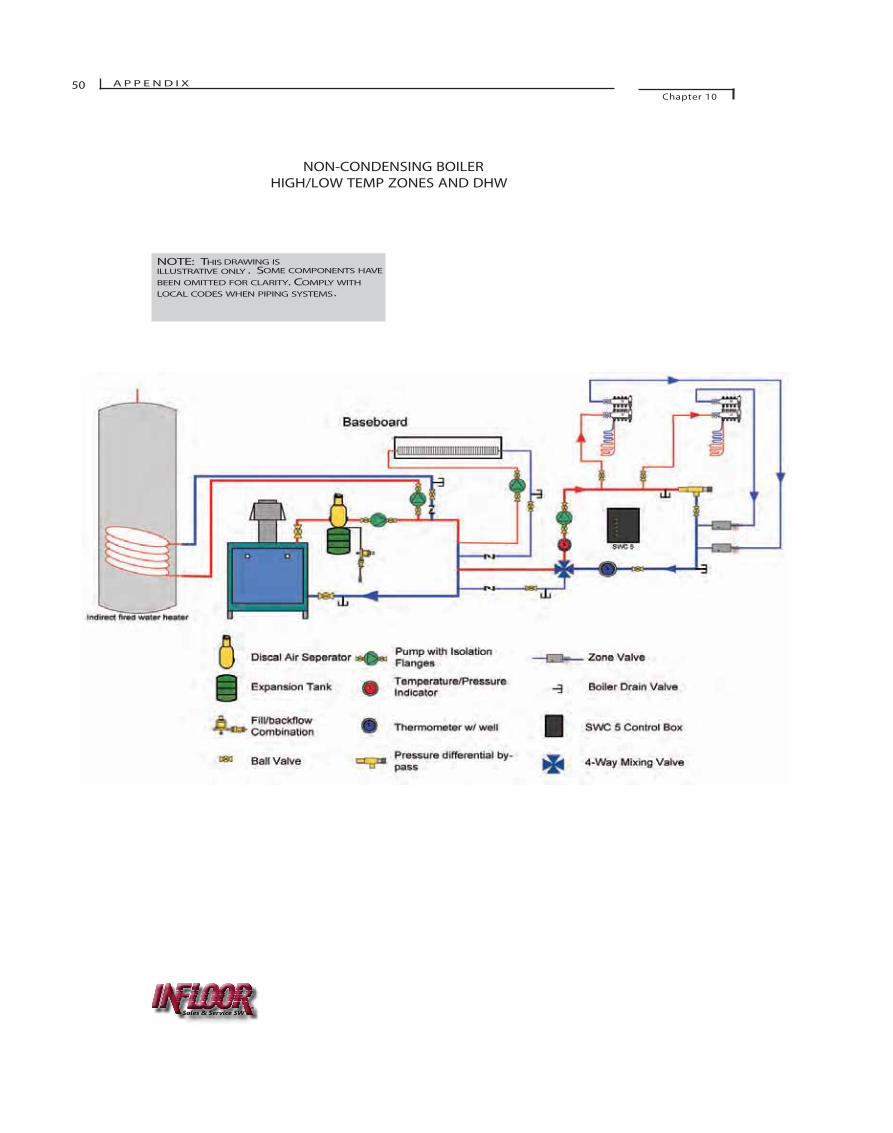
50 A P P E N D I XChapter 10
NON-CONDENSING BOILERHIGH/LOW TEMP ZONES AND DHW
NOTE: THIS DRAWING ISILLUSTRATIVE ONLY . SOME COMPONENTS HAVE
BEEN OMITTED FOR CLARITY. COMPLY WITHLOCAL CODES WHEN PIPING SYSTEMS.
Sales & Service SW
Sales & Service SW
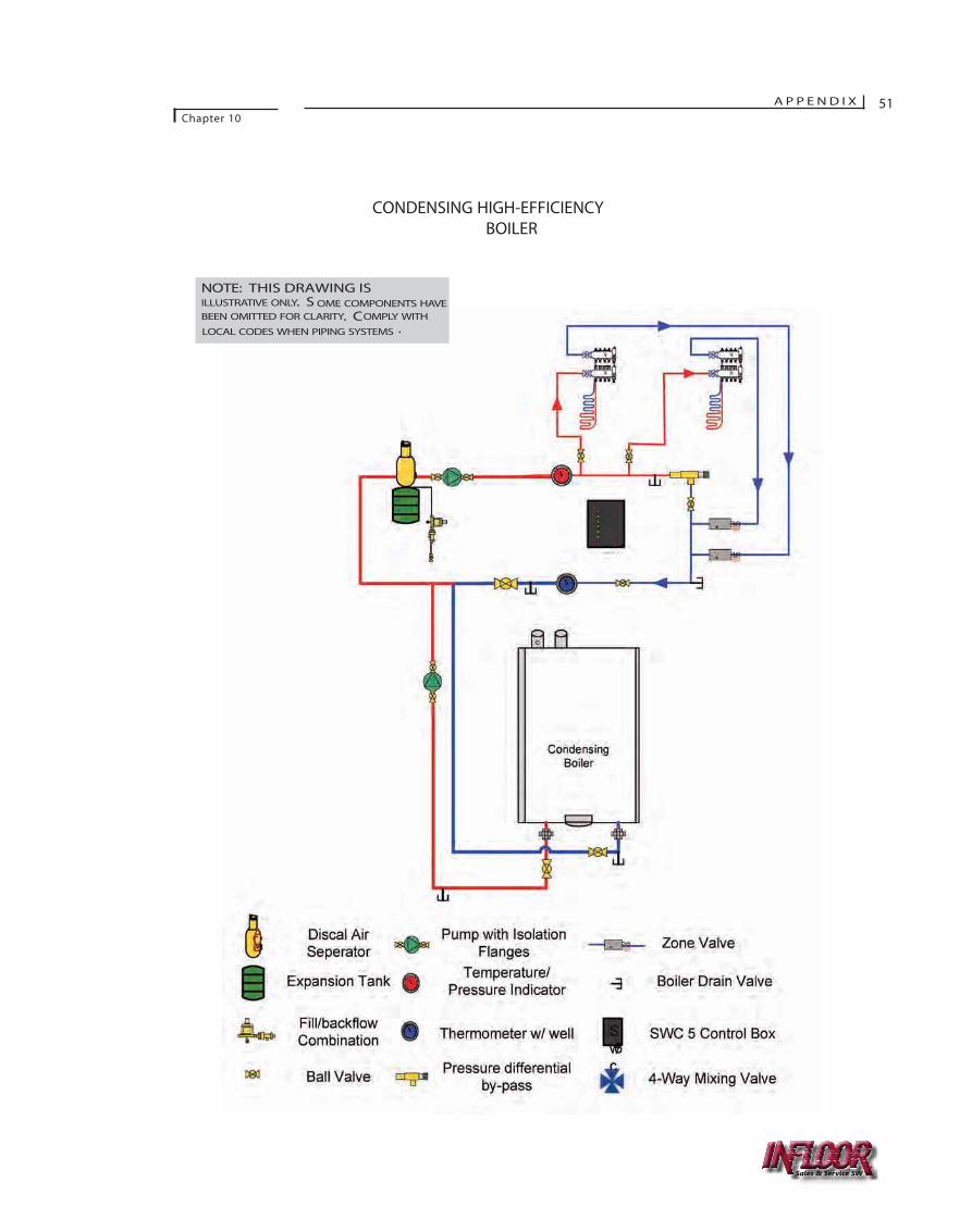
A P P E N D I XChapter 10
51
CONDENSING HIGH-EFFICIENCYBOILER
NOTE: THIS DRAWING ISILLUSTRATIVE ONLY. S OME COMPONENTS HAVEBEEN OMITTED FOR CLARITY. COMPLY WITH
LOCAL CODES WHEN PIPING SYSTEMS .
Sales & Service SW
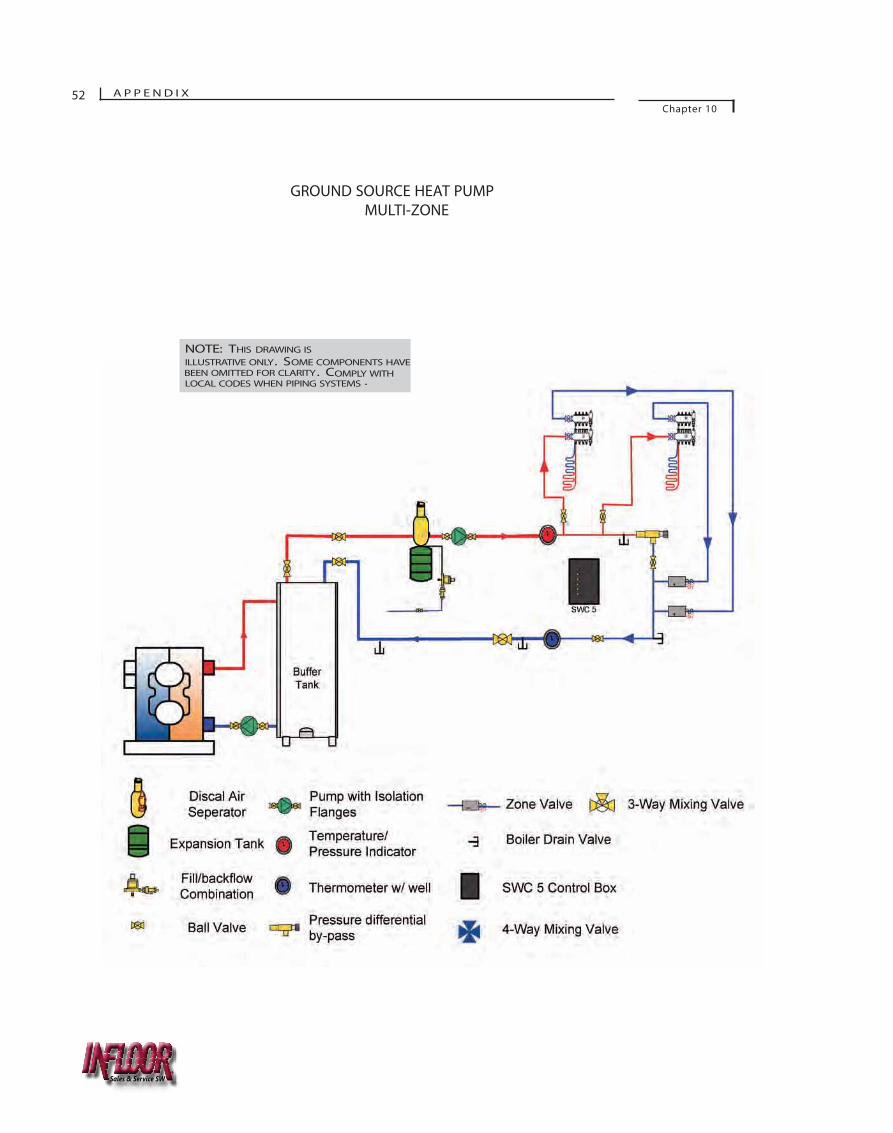
52 A P P E N D I XChapter 10
GROUND SOURCE HEAT PUMPMULTI-ZONE
NOTE: THIS DRAWING ISILLUSTRATIVE ONLY. SOME COMPONENTS HAVEBEEN OMITTED FOR CLARITY. COMPLY WITHLOCAL CODES WHEN PIPING SYSTEMS .
Sales & Service SW
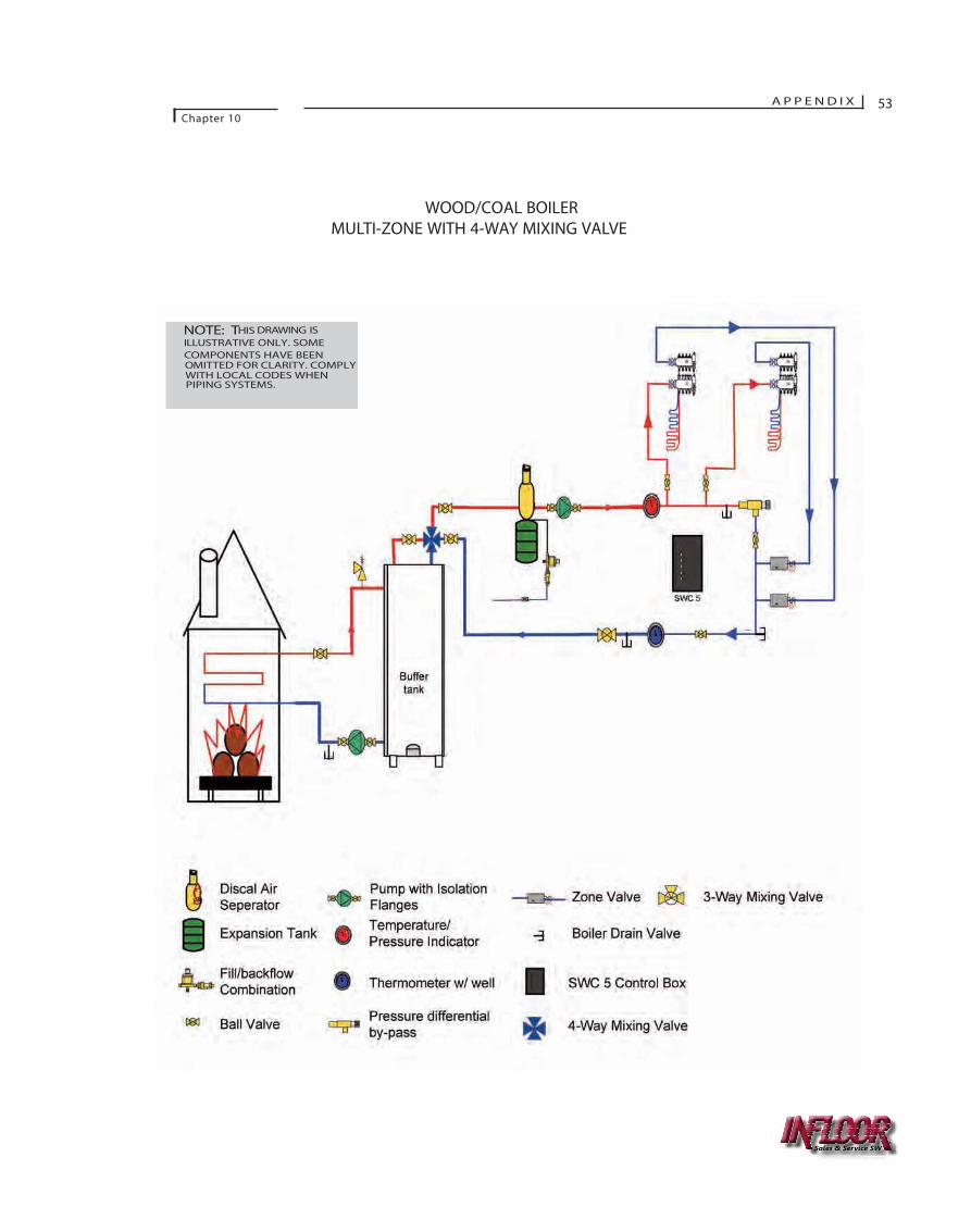
WOOD/COAL BOILERMULTI-ZONE WITH 4-WAY MIXING VALVE
A P P E N D I XChapter 10
53
NOTE: THIS DRAWING ISILLUSTRATIVE ONLY. SOME
COMPONENTS HAVE BEENOMITTED FOR CLARITY. COMPLYWITH LOCAL CODES WHENPIPING SYSTEMS.
Sales & Service SW
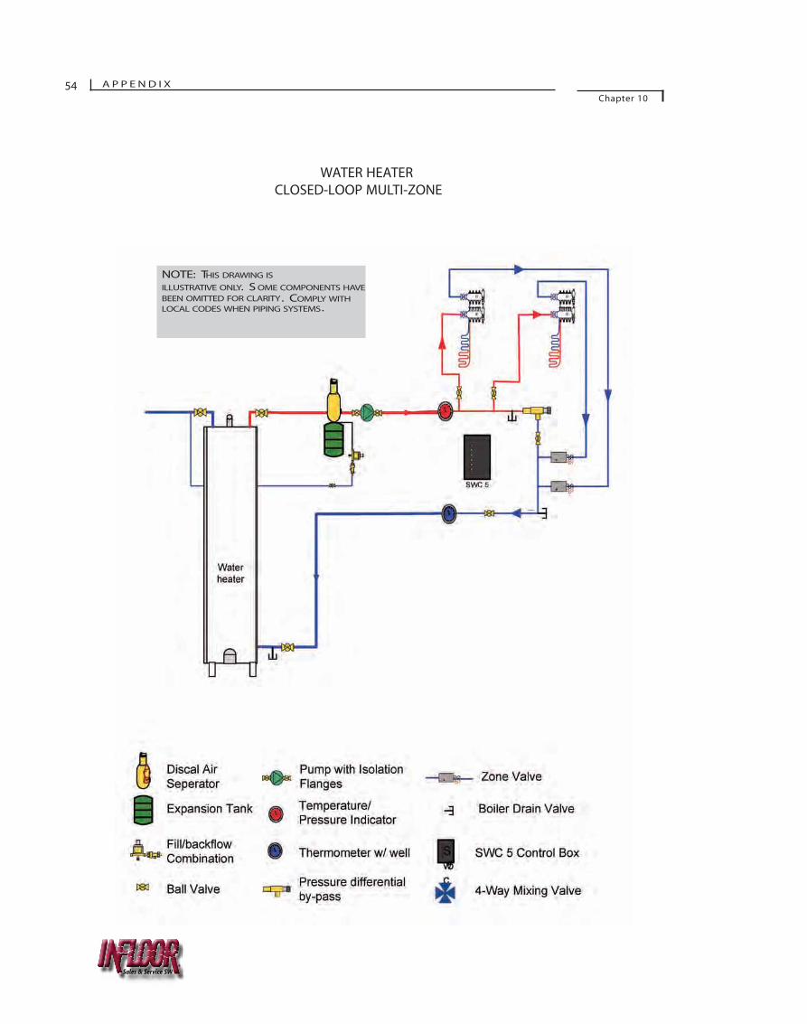
WATER HEATERCLOSED-LOOP MULTI-ZONE
54 A P P E N D I XChapter 10
NOTE: THIS DRAWING IS
ILLUSTRATIVE ONLY. S OME COMPONENTS HAVEBEEN OMITTED FOR CLARITY. COMPLY WITHLOCAL CODES WHEN PIPING SYSTEMS.
Sales & Service SW
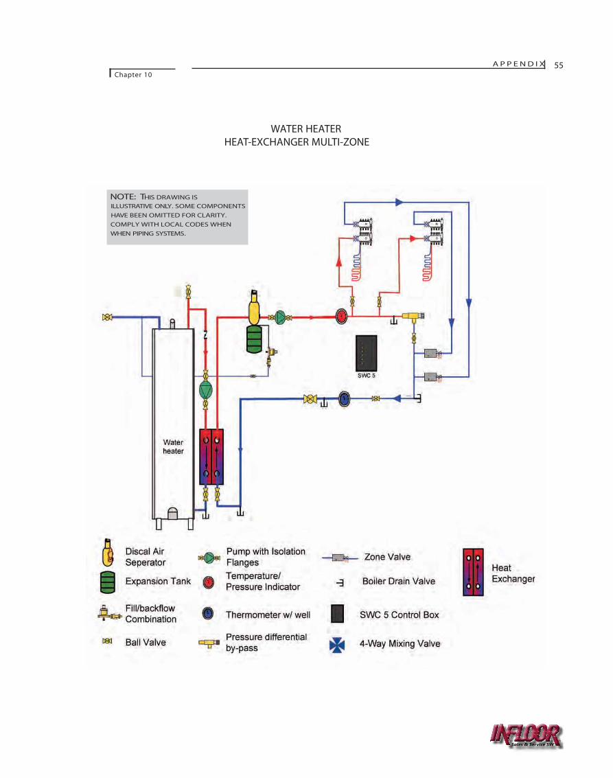
WATER HEATERHEAT-EXCHANGER MULTI-ZONE
A P P E N D I XChapter 10
55
NOTE: THIS DRAWING ISILLUSTRATIVE ONLY. SOME COMPONENTSHAVE BEEN OMITTED FOR CLARITY.COMPLY WITH LOCAL CODES WHENWHEN PIPING SYSTEMS.
Sales & Service SW
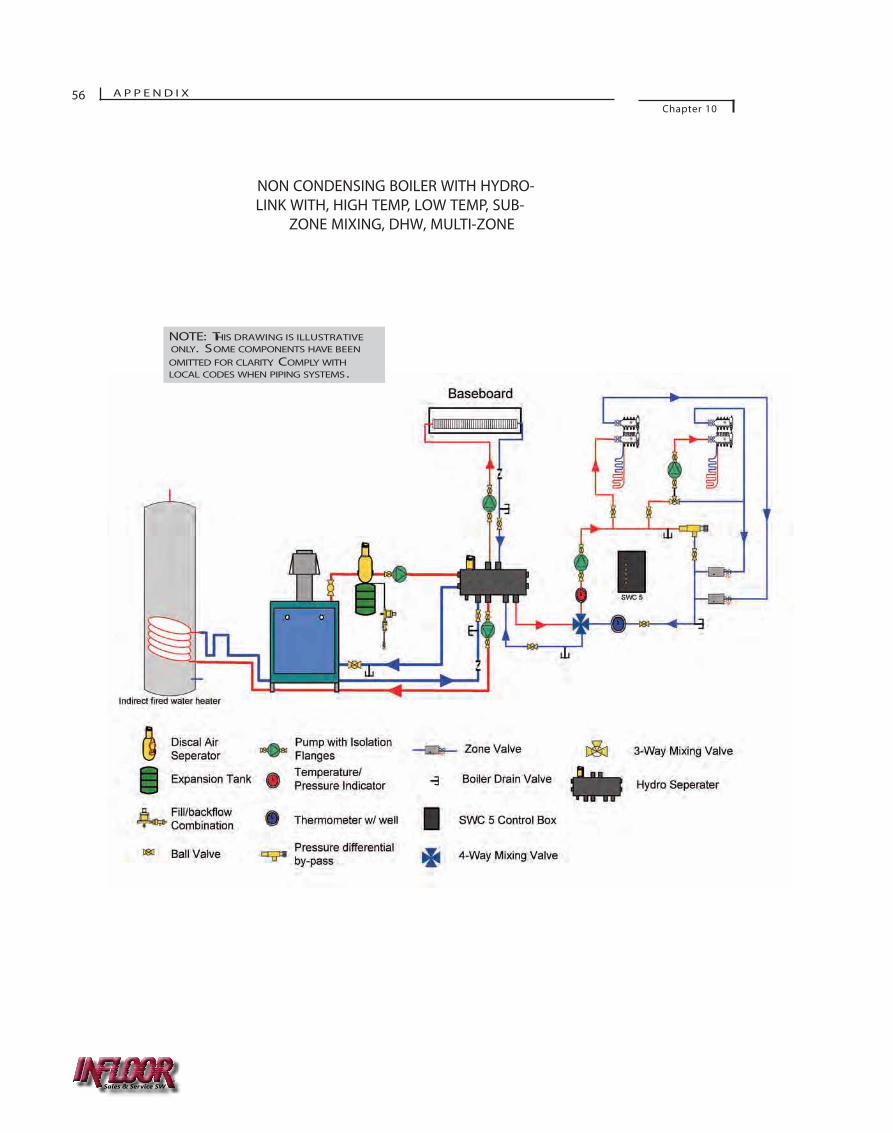
56 A P P E N D I XChapter 10
W ood/CoalBoi ler NON CONDENSING BOILER WITH HYDRO-LINK WITH, HIGH TEMP, LOW TEMP, SUB-
ZONE MIXING, DHW, MULTI-ZONE
NOTE: THIS DRAWING IS ILLUSTRATIVE ONLY. SOME COMPONENTS HAVE BEENOMITTED FOR CLARITY. COMPLY WITHLOCAL CODES WHEN PIPING SYSTEMS.
Sales & Service SW
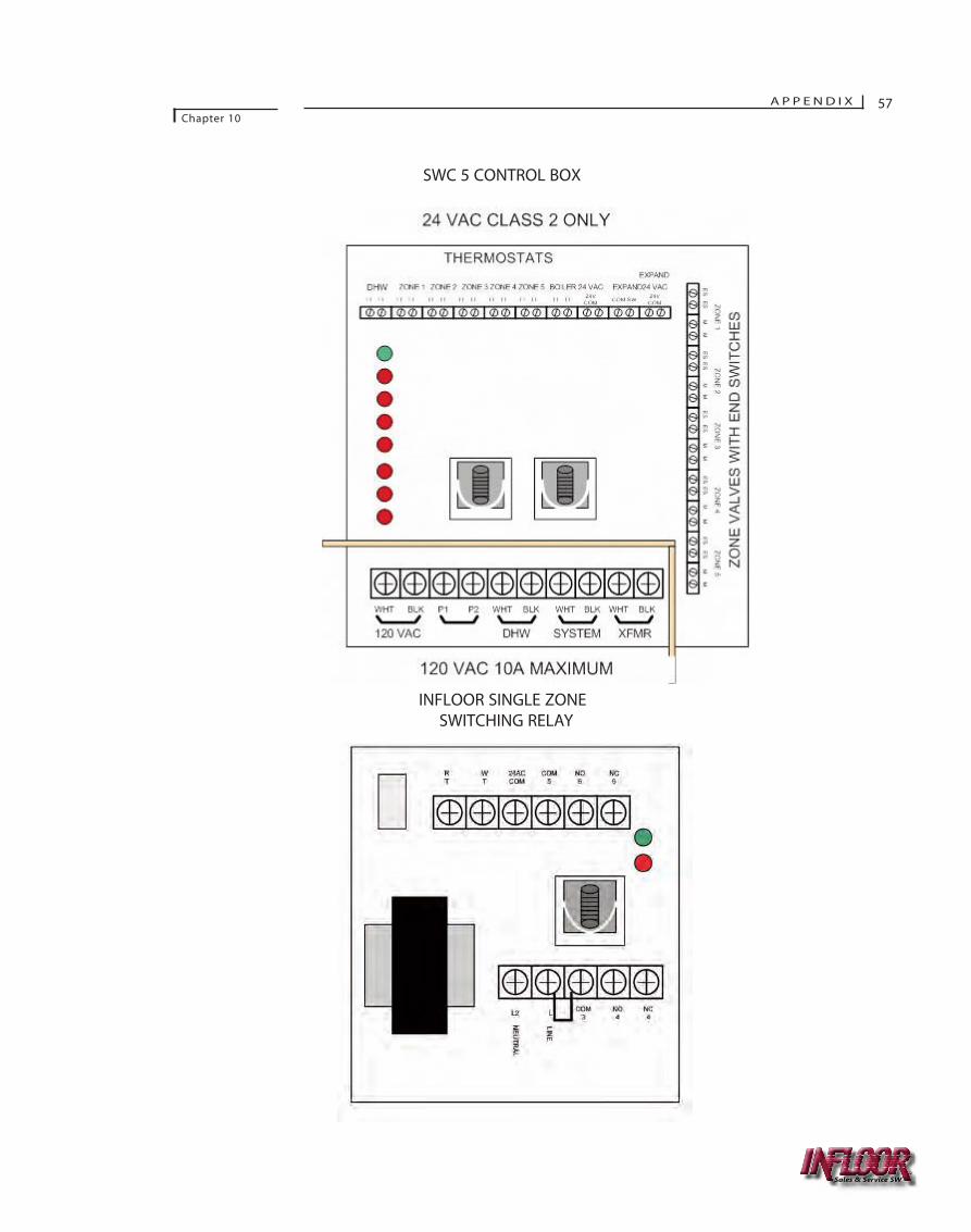
A P P E N D I XChapter 10
57
SWC 5 CONTROL BOX
INFLOOR SINGLE ZONE SWITCHING RELAY
Sales & Service SW
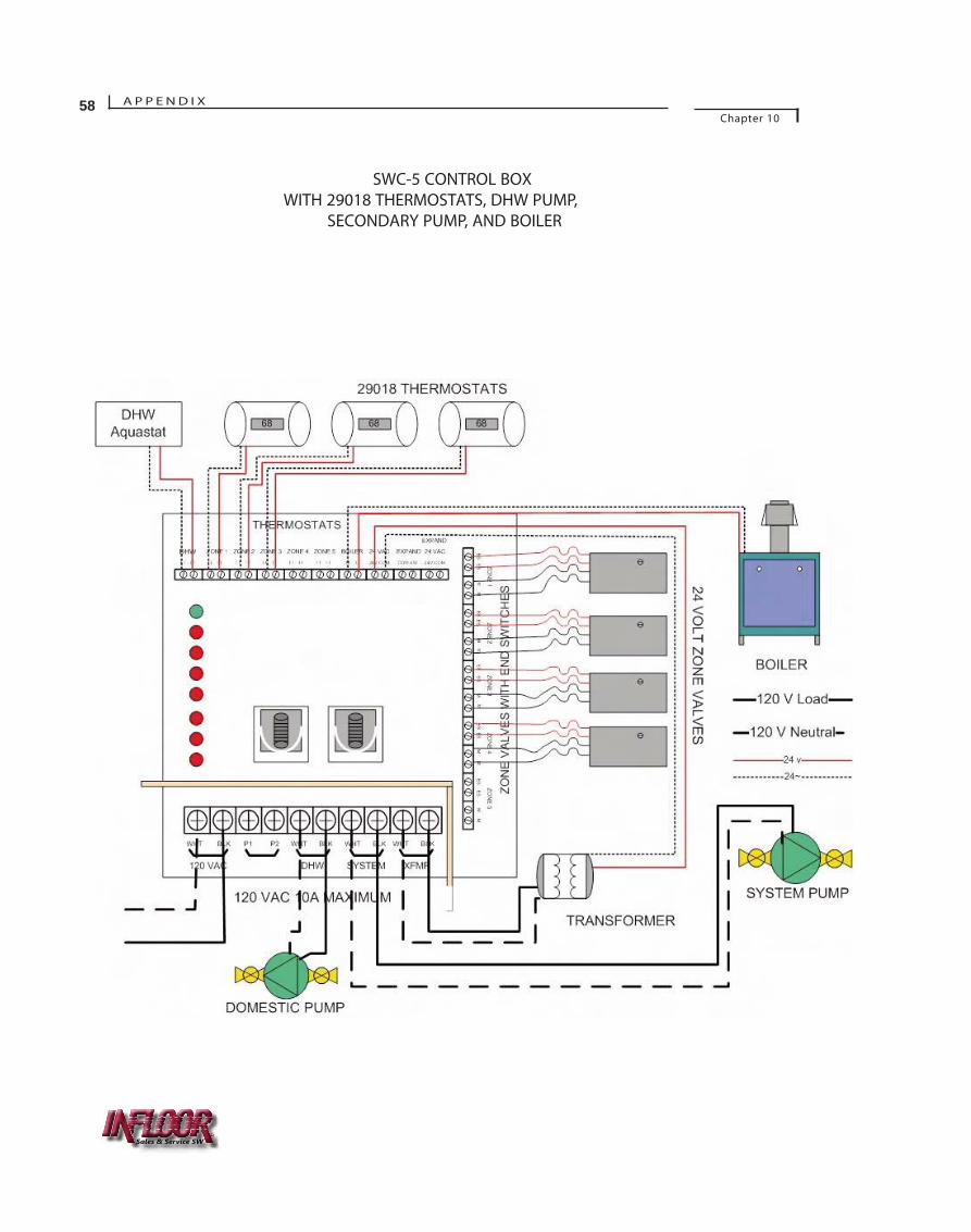
A P P E N D I XChapter 10
58
SWC-5 CONTROL BOXWITH 29018 THERMOSTATS, DHW PUMP,
SECONDARY PUMP, AND BOILER
Sales & Service SW
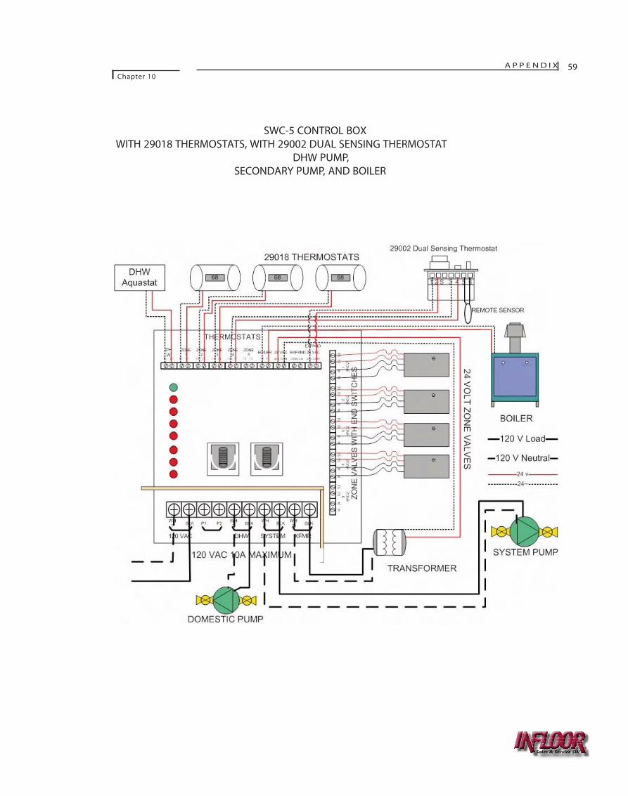
A P P E N D I XChapter 10
59
SWC-5 CONTROL BOXWITH 29018 THERMOSTATS, WITH 29002 DUAL SENSING THERMOSTAT
DHW PUMP,SECONDARY PUMP, AND BOILER
Sales & Service SW
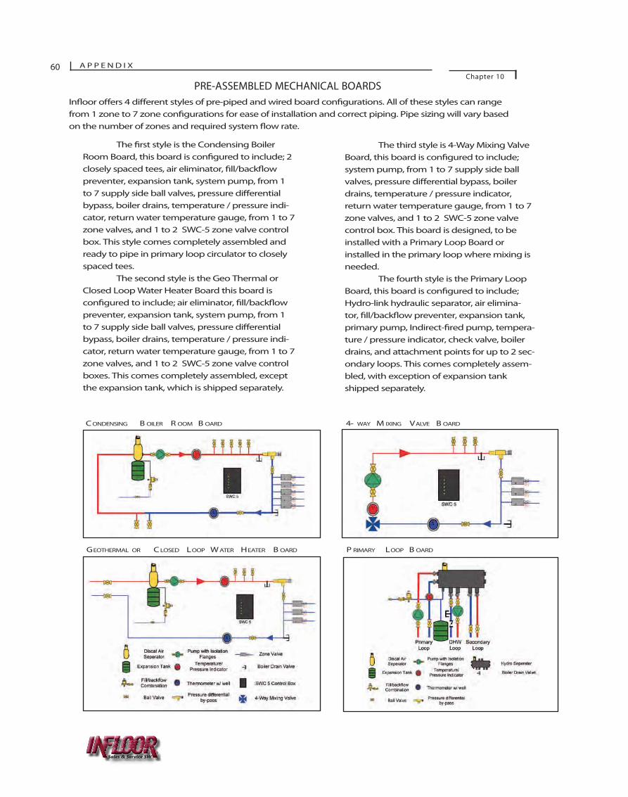
The �rst style is the Condensing BoilerRoom Board, this board is con�gured to include; 2closely spaced tees, air eliminator, �ll/back�owpreventer, expansion tank, system pump, from 1to 7 supply side ball valves, pressure di�erentialbypass, boiler drains, temperature / pressure indi-cator, return water temperature gauge, from 1 to 7zone valves, and 1 to 2 SWC-5 zone valve controlbox. This style comes completely assembled andready to pipe in primary loop circulator to closelyspaced tees.
The second style is the Geo Thermal orClosed Loop Water Heater Board this board iscon�gured to include; air eliminator, �ll/back�owpreventer, expansion tank, system pump, from 1to 7 supply side ball valves, pressure di�erentialbypass, boiler drains, temperature / pressure indi-cator, return water temperature gauge, from 1 to 7zone valves, and 1 to 2 SWC-5 zone valve controlboxes. This comes completely assembled, exceptthe expansion tank, which is shipped separately.
The third style is 4-Way Mixing ValveBoard, this board is con�gured to include;system pump, from 1 to 7 supply side ballvalves, pressure di�erential bypass, boilerdrains, temperature / pressure indicator,return water temperature gauge, from 1 to 7zone valves, and 1 to 2 SWC-5 zone valvecontrol box. This board is designed, to beinstalled with a Primary Loop Board orinstalled in the primary loop where mixing isneeded.
The fourth style is the Primary LoopBoard, this board is con�gured to include;Hydro-link hydraulic separator, air elimina-tor, �ll/back�ow preventer, expansion tank,primary pump, Indirect-�red pump, tempera-ture / pressure indicator, check valve, boilerdrains, and attachment points for up to 2 sec-ondary loops. This comes completely assem-bled, with exception of expansion tankshipped separately.
60 A P P E N D I XChapter 10
C ONDENSING B OILER R OOM B OARD 4- WAY M IXING VALVE B OARD
In�oor o�ers 4 di�erent styles of pre-piped and wired board con�gurations. All of these styles can rangefrom 1 zone to 7 zone con�gurations for ease of installation and correct piping. Pipe sizing will vary basedon the number of zones and required system �ow rate.
GEOTHERMAL OR C LOSED LOOP W ATER HEATER B OARD
PRE-ASSEMBLED MECHANICAL BOARDS
P RIMARY LOOP B OARD
Sales & Service SW
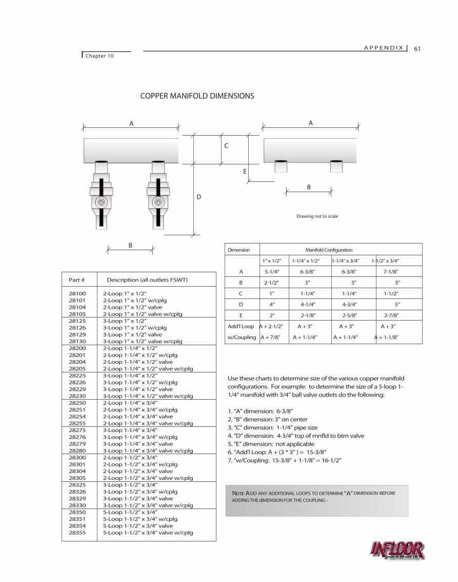
COPPER MANIFOLD DIMENSIONS
A P P E N D I XChapter 10
61
Dimension Manifold Con�guration
1” x 1/2” 1-1/4” x 1/2” 1-1/4” x 3/4” 1-1/2” x 3/4”
A 5-1/4” 6-3/8” 6-3/8” 7-1/8”
B 2-1/2” 3” 3” 3”
C 1” 1-1/4” 1-1/4” 1-1/2”
D 4” 4-1/4” 4-3/4” 5”
E 2” 2-1/8” 2-5/8” 2-7/8”
Add’l Loop A + 2-1/2” A + 3” A + 3” A + 3”
w/Coupling A + 7/8” A + 1-1/4” A + 1-1/4” A + 1-1/8”
Use these charts to determine size of the various copper manifoldcon�gurations. For example: to determine the size of a 5-loop 1-1/4” manifold with 3/4” ball valve outlets do the following:
1. “A” dimension: 6-3/8” 2. “B” dimension: 3” on center3. “C” dimension: 1-1/4” pipe size4. “D” dimension: 4-3/4” top of mn�d to btm valve5. “E” dimension: not applicable6. “Add’l Loop: A + (3 * 3” ) = 15-3/8”7. “w/Coupling: 15-3/8” + 1-1/8” = 16-1/2”
NOTE: ADD ANY ADDITIONAL LOOPS TO DETERMINE “A” DIMENSION BEFORE
ADDING THE dIMENSION FOR THE COUPLING .
Part # Description (all outlets FSWT)
28100 2-Loop 1” x 1/2” 28101 2-Loop 1” x 1/2” w/cplg28104 2-Loop 1” x 1/2” valve28105 2-Loop 1” x 1/2” valve w/cplg28125 3-Loop 1” x 1/2” 28126 3-Loop 1” x 1/2” w/cplg28129 3-Loop 1” x 1/2” valve28130 3-Loop 1” x 1/2” valve w/cplg28200 2-Loop 1-1/4” x 1/2” 28201 2-Loop 1-1/4” x 1/2” w/cplg28204 2-Loop 1-1/4” x 1/2” valve28205 2-Loop 1-1/4” x 1/2” valve w/cplg28225 3-Loop 1-1/4” x 1/2” 28226 3-Loop 1-1/4” x 1/2” w/cplg28229 3-Loop 1-1/4” x 1/2” valve28230 3-Loop 1-1/4” x 1/2” valve w/cplg28250 2-Loop 1-1/4” x 3/4” 28251 2-Loop 1-1/4” x 3/4” w/cplg28254 2-Loop 1-1/4” x 3/4” valve28255 2-Loop 1-1/4” x 3/4” valve w/cplg28275 3-Loop 1-1/4” x 3/4” 28276 3-Loop 1-1/4” x 3/4” w/cplg28279 3-Loop 1-1/4” x 3/4” valve28280 3-Loop 1-1/4” x 3/4” valve w/cplg28300 2-Loop 1-1/2” x 3/4” 28301 2-Loop 1-1/2” x 3/4” w/cplg28304 2-Loop 1-1/2” x 3/4” valve28305 2-Loop 1-1/2” x 3/4” valve w/cplg28325 3-Loop 1-1/2” x 3/4” 28326 3-Loop 1-1/2” x 3/4” w/cplg28329 3-Loop 1-1/2” x 3/4” valve28330 3-Loop 1-1/2” x 3/4” valve w/cplg28350 5-Loop 1-1/2” x 3/4” 28351 5-Loop 1-1/2” x 3/4” w/cplg28354 5-Loop 1-1/2” x 3/4” valve28355 5-Loop 1-1/2” x 3/4” valve w/cplg
Drawing not to scale
A A
B
B
E
C
D
Sales & Service SW
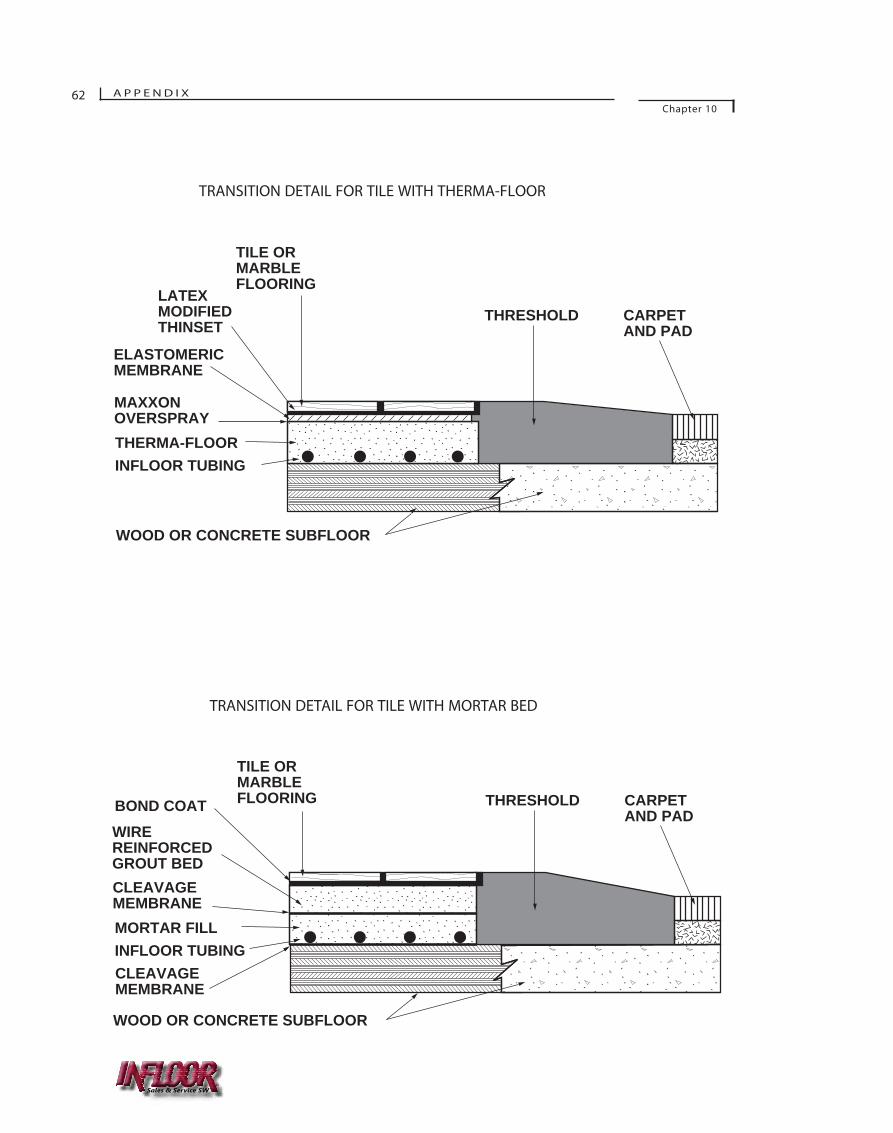
THRESHOLD CARPET AND PAD
WOOD OR CONCRETE SUBFLOOR
TILE OR MARBLE FLOORING
LATEX MODIFIED THINSET
ELASTOMERIC MEMBRANE
THERMA-FLOORINFLOOR TUBING
MAXXON OVERSPRAY
68
THRESHOLD CARPET AND PAD
WOOD OR CONCRETE SUBFLOOR
TILE OR MARBLE FLOORINGBOND COAT
WIRE REINFORCED GROUT BED
MORTAR FILLINFLOOR TUBING
CLEAVAGE MEMBRANE
CLEAVAGE MEMBRANE
69
TRANSITION DETAIL FOR TILE WITH THERMA-FLOOR
TRANSITION DETAIL FOR TILE WITH MORTAR BED
62 A P P E N D I XChapter 10
Sales & Service SW
DEFINITIONS
British Thermal Unit (Btu) - A unit for measuring quantity of heat. It is approximately the heat required to raise the temperature of one pound of water onedegree Fahrenheit.
Btu per hour - A unit for measuring the rate of heat transfer.
Conduction, thermal - Heat transfer through a material in which energy is transmitted from particle to particle without displacement of the particles.
Convection - Heat transfer by movement of uid. Natural convection is due to
in density from temperature Forced convection is produced
by mechanical means.
Degree day - A unit, based on temperature and time, used in estimating
heating system energy consumption. For any one day for which the mean temperature is below 65 °F, the degree days for that day is the di ence between 65 °F and the mean for that day. Degree days for any period is the sum of the degree days for each day in that period.
Design temperature - The temperature an apparatus or a system is designed to maintain (inside design temperature) or operate against (outside design temperature) under the most extreme conditions to be The di erence between the inside and the outside design temperatures is the design temperature
.
In ltration - Air owing inward through a crack between the window and frame, or door and frame, or frame and wall, etc.
Installed resistance, (R-) - The thermal resistance of insulation when applied according to the manufacturer’s
instructions in the building section that is described.
Perm - The unit of measurement of permeance equal to 1 grain divided by (square feet x hour x inch of mercury vapor pressure erence).
Permeance - The water vapor permeance of a material (or combination of materials between parallel surfaces) is the ratio of
water vapor ow [grains divided by (squarefeet x hour)] to the vapor pressure
ce (inches of mercury) between its surfaces.
Radiation, thermal - The transmission of heat through space by wave motion. The passage of heat from one object to another without warming the space in between.
Temperature - The thermal state of matter with reference to its tendency to communicate heat to matter in contact with it. If no heat upon contact, there is no di in temperature.
Thermal conductance, (C) - The number of heat units (Btu) that will pass through one square foot of nonuniform material in one hour for each degree of Fahrenheit
temperature erence between the two surfaces of the material.
Thermal conductivity (k) - The number of heat units (Btu) that will pass through one square foot of a uniform material one inch thick in one hour for each degree of Fahrenheit temperature di erence between the two surfaces of the material.
Thermal resistance, (R) - The ability of a material or combination of materials to retard or resist the ow of heat. It is the reciprocal of “U”.
Thermal resistivity, (r) - The ability of a unit thickness of a uniform material to retard or resist the ow of heat. It is the reciprocal of thermal conductivity (l/k).
A P P E N D I XChapter 10
63
Sales & Service SW
Transmission - A general term for heat travel (by conduction, convection, radiation, or any combination thereof) in thermal load calculations.
“U” (Overall coe�cient of heat transfer) - The amount of heat �ow, expressed in Btu per hour x square feet x degree Fahrenheit temperature di�erence, between the air on the inside and the air on the outside of a building section (wall, �oor, roof or ceiling). The term is applied to combinations of materials, and also to single materials, such as window glass, and includes the surface conductance on both sides. This term is frequently called the “U value”. (For conversion, U = 3.413W.)
Vapor barrier - A material which retards the transmission of water vapor. (Permeance not more than 1 perm.)
Ventilation - The process of supplying or removing air, naturally or mechanically, to or from any space.
“W” - The U factor converted into electrical terms for calculations for electricheating. It is the amount of heat �ow, expressed in watts per square foot x degreeFahrenheit temperature di�erence, between the air on the inside and the air on the outside of a building section (wall, �oor, roof or ceiling). (For conversion, W = 0.293 U.)
Watt - The rate of �ow of electrical energy (not the quantity, but the rate.) One watt is equivalent to 3.413 Btu/hr.
64 A P P E N D I XChapter 10
Sales & Service SW

SECTION 15770 (Manifold Version)HEAT TRANSFER UNITS
RECOMMENDED SPECIFICATION FORHYDRONIC INFLOOR ® HEATING SYS-TEMS WITH CROSS-LINKED POLYETH -YLENE BARRIER/NON-BARRIERTUBING AS THE EQUIPMENT FORRESIDENTIAL/LIGHT COMMERCIALRADIANT FLOOR HEATING
PART 1 GENERAL
1.01 SUMMARY
A . Conditions of the Contract: The Conditions of the Contract (General, Supplementary and other Conditions) and the General Requirements (sections of Division 1) govern the provisions of this section. The articles contained in this section may modify, delete or add to the provisions of the Conditions of the Contract.
1.02 SECTION INCLUDES
A. In�oor manifold
B. In�oor tubing
C. Primary boiler loop and circulating pump
D. System treatment
E. Therma-Floor ® underlayment
1.03 SUBMITTALS
A. Product Data: Provide for manufactured products and assemblies including installation recommendations and rough-in dimensions.
B. Operating and Maintenance Instructions:Include manufacturer’s descriptive literature, operating instructions, maintenance and repair data, and parts description.
1.04 WARRANTY
A. Provide twenty-�ve (25) year manufacturer’s warranty for In�oor tubing and one (1) year manufacturer’s warranty for In�oor components.
1.05 QUALITY ASSURANCE
A. Installer’s Quali�cations: Installation of In�oor Heating System shall be by a trained In�oor dealer authorized by
In�oor Inc.
B. Pressure Test: Provide hydrostatic test of primary loop, manifolds, and tubing to 100 psi (689.5 kPa) for 30 minutes.
1.06 DELIVERY AND STORAGE HANDLING
A. General Requirements: Materials shall be delivered in their original, unopened packages, and protected from exposure to the elements. Damaged or deteriorated materials shall be removed from the premises.
PART 2 PRODUCTS
2.01 MATERIALS
A. In�oor manifold: Furnish and install a complete radiant heating system that includes modular copper manifolds con-
tainingsupply and return outlets with bal-ancing adjustment for each cir-cuit. Balance each circuit to maintaineven temperature in spaces. In�oormanifolds as furnished by In�oor Inc., BuenaVista, CO.
B. In�oor tubing: Radiant tubing shall be _______________ (Choose one of the following: In�oor barrier cross-linked polyethylene [BPEX, 3/8" {10 mm} or 1/2" {13 mm}], or In�oor cross-linked polyethylene [PEX, 3/8" {10 mm} or 1/2" {13 mm}]). Tubing to be furnished by In�oor Inc, Buena Vista, CO
and is to be installed in complete accord to manufacturer’s instructions.
1. In�oor barrier cross-linked polyethylene (BPEX) as provided by In�oor Inc, Buena Vista, CO:nominal 3/8" (inch) [10 mm] inside diameter with an nominal 1/2" (inch) [13 mm] outside diameter with a wallthickness of 0.059" (inch) [1.5 mm],
A P P E N D I XChapter 10
65
Sales & Service SW
rated for 100 psig (689.5 kPa) at 180 degrees F (82.2 degrees C) with an external ethylene vinyl alcohol (EVOH) oxygen di�usion barrier allowing no more than 0.1 gram per cubic meter per day (0.1g/m3/d). Individual circuit length to be up to 300' (feet) [90 m] maximum.
2. In�oor barrier cross-linked polyethylene (BPEX) as provided by In�oor Inc. , Buena Vista, CO:
nominal 1/2" (inch) [13 mm] inside diameter with an nominal 5/8" (inch) [16 mm] outside diameter with a wallthickness of 0.059" (inch) [1.5 mm], rated for 100 psig (689.5 kPa) at 180 degrees F (82.2 degrees C) with an external ethylene vinyl alcohol (EVOH) oxygen di�usion barrier allowing no more than 0.1 gram per cubic meter per day (0.1g/m3/d). Individual circuit length to be up to 300' (feet) [90 m] maximum.
3. In�oor cross-linked polyethylene (PEX) as provided by In�oor Inc. ,
Buena Vista, CO: nominal 3/8" (inch) [10 mm] inside diameter
with an nominal 1/2" (inch) [13 mm] outside diameter with a wall
thickness of 0.059" (inch) [1.5 mm], rated for 100 psig (689.5 kPa) at 180 degrees F (82.2 degrees C. Individual circuit length to be up to 300' (feet) [90 m] maximum.
4. In�oor cross-linked polyethylene (PEX) as provided by In�oor Inc. ,
Buena Vista, CO: nominal 1/2" (inch) [12.7 mm] inside diameter with an nominal 5/8" (inch) [15.87 mm] outside diameter with a wall thickness of 0.062" (inch) [1.575 mm], manufactured in accordance with ASTM standard D-3309 and rated for 100 psi (689.5 kPa) at 180 degrees F (82.2 degrees C).
Individual circuit length to be up to 300' (feet) [90 m] maximum.
C. Primary boiler loop and circulating pump: Primary circulating loop shall be supplied by others with su�cient systemwater �ow to provide boiler supply temperature between 140 degrees F (60.0 degrees C) to 180 degrees F (82.2 degrees C) ,unless using condensing boil-
er or water heater,with a 20 degree F (11degree C) maximum temperaturedrop between primary loop supplyand return piping.
D. System Treatment: Install _______________ (Choose one of the following: Formula 10 ™ , or In�oor System Treatment.)
1. Formula 10, a silicate-based corrosioninhibitor in concentration of one (1) quart [0.95 liter] treatment per �fty (50) gallons [190 liters] water as provided by In�oor Inc. , Buena Vista,
CO NOTE: Not to be used with glycol additives.
2. In�oor system treatment, a borate-nitrite corrosion inhibitor in concentration of 1400 ppm (one [1] gallon {3.8 liters} treatment per �fty [50] gallons {189.3 liters} water) as provided by In�oor Inc. ,
Buena Vista, CO
E. Therma-Floor Underlayment: Floor underlayment shall be Therma-Floor ®by Maxxon Corporation, Hamel, MN (see section 03540)
END OF SECTION
66 A P P E N D I XChapter 10
Sales & Service SW

www r.com1/07
PO Box 4945• Buena Vista,Colorado 81211 USA
1-800-608-0562 fax: 719-395-3555
RESIDENTIAL SNOW & ICE MELT COMMERCIAL
Radiant Floor Specialists Since 1985
Sales & Service SW