RESERVOIR VENT VALVE ASSEMBLY PART NUMBER …Glyd-ring (20) with sizer as shown in Figure 3. Replace...
23
29-11-02 Page T-1 May 2, 1983 Essex Industries, Inc. Manufacturing Division #6 Sunnen Drive St. Louis, MO 63143-3903 RESERVOIR VENT VALVE ASSEMBLY PART NUMBER 0091520200-2 COMPONENT MAINTENANCE MANUAL WITH ILLUSTRATED PARTS LIST
Transcript of RESERVOIR VENT VALVE ASSEMBLY PART NUMBER …Glyd-ring (20) with sizer as shown in Figure 3. Replace...

29-11-02 Page T-1 May 2, 1983
Essex Industries, Inc. Manufacturing Division #6 Sunnen Drive St. Louis, MO 63143-3903 RESERVOIR VENT VALVE ASSEMBLY PART NUMBER 0091520200-2 COMPONENT MAINTENANCE MANUAL WITH ILLUSTRATED PARTS LIST

ESSEX INDUSTRIES, INC. MANUFACTURING DIVISION 3235 BIG BEND BLVD ST. LOUIS MO 63143-3903
29-11-02 Page RR-1 May 2, 1983
RECORD OF REVISIONS Retain this record in the front of the manual or chapter. On receipt of revisions, insert revised pages in the manual and enter revision number, date inserted, and initials.
REV. NO.
INSERTION DATE
BY
REV. NO.
INSERTION DATE
BY
REV. NO.
INSERTION DATE
BY

ESSEX INDUSTRIES, INC. MANUFACTURING DIVISION 3235 BIG BEND BLVD ST. LOUIS MO 63143-3903
29-11-02 Page TR/SB-2 May 2, 1983
RECORD OF TEMPORARY REVISIONS AND SERVICE BULLETINS Retain this record in the front of the manual or chapter. On receipt of revisions, insert revised pages in the manual and enter revision number, date inserted, and initials.
REV. NO.
INSERTION DATE
BY
REV. NO.
INSERTION DATE
BY
REV. NO.
INSERTION DATE
BY

ESSEX INDUSTRIES, INC. MANUFACTURING DIVISION 3235 BIG BEND BLVD ST. LOUIS MO 63143-3903
29-11-02 Page LEP-1 Jul 11, 2002
LIST OF EFFECTIVE PAGES Chapter/Section Page Date
Title Page T-1 May 2/83 Record of Revisions RR-1 May 2/83 Record of Temporary Revisions and Service Bulletins TR/SB-1 May 2/83 List of Effective Pages LEP-1 Jul 11/02 Table of Contents T/C-1 May 2/83 Introduction INTRO-1 May 2/83 Description and Operation 1 Jul 11/02 Testing and Trouble Shooting 1 May 2/83 Disassembly 3 May 2/83 Cleaning 3 May 2/83 Check 4 May 2/83 Repair 4 May 2/83 Assembly 5 May 2/83 Fault Isolation Diagram 7 May 2/83 Fits and Clearances 8 May 2/83 Special Tools 8 May 2/83 Illustrated Parts List 9 May 2/83 IPL Figure 1 13 May 2/83 Figure 6 14 July 11/02

ESSEX INDUSTRIES, INC. MANUFACTURING DIVISION 3235 BIG BEND BLVD ST. LOUIS MO 63143-3903
29-11-02 Page T/C-1 May 2, 1983
TABLE OF CONTENTS Paragraph Title Page DESCRIPTION AND OPERATION..................................................................................1 TESTING AND TROUBLESHOOTING............................................................................1 DISASSEMBLY ...............................................................................................................3 CLEANING ......................................................................................................................3 CHECK ............................................................................................................................4 REPAIR ...........................................................................................................................4 ASSEMBLY .....................................................................................................................5 FAULT ISOLATION DIAGRAM..… … … … … … … … … … … … … … … … … … … … … … … … 7 FITS AND CLEARANCES ...............................................................................................8 SPECIAL TOOLS, FIXTURES, AND EQUIPMENT .........................................................8 ILLUSTRATED PARTS LIST...........................................................................................9 IPL FIGURE 1… … … … … … … … … … … … … … … … … … … … … … … … … … … … … … … ..13 FIGURE 6… … … ..… … … … … … … … … … … … … … … … … … … … … … … … … … … … … ..14

ESSEX INDUSTRIES, INC. MANUFACTURING DIVISION 3235 BIG BEND BLVD ST. LOUIS MO 63143-3903
29-11-02 Page INTRO-1 May 2, 1983
INTRODUCTION The instructions contained in this manual provide information necessary to understand the valve operation and allow the mechanic to perform maintenance functions consisting of: testing, disassembly, assembly, inspection and complete shop-type repair. The manual is divided into separate sections. Refer to the Table of Contents for the page location of a particular section. Some assembly tools are special in nature and are listed by part number in the Assembly section of this manual. The balance of assembly tools and all test equipment are universally applicable and are commercially available. Where a particular item of non-special equipment includes a manufacturer and model number, equal or better equipment may be substituted. An explanation of the use of the Illustrated Parts List is provided in the Introduction to that section. The manual will be revised as necessary to reflect current information. Verification Testing Verified 5-2-83 DisassembIy Verified 5-2-83 Assembly Verified 5-2-83

ESSEX INDUSTRIES, INC. MANUFACTURING DIVISION 3235 BIG BEND BLVD ST. LOUIS MO 63143-3903
29-11-02 Page 1
Jul 11, 2001
1. DESCRIPTION AND OPERATION
A. Physical Description
1. The reservoir vent valve is a vent valve incorporating an integral check valve. The valve is designed to retain pressure in a remote hydraulic fluid reservoir when in the normal mode (see Figure 1) and to release pressure when manually actuated to the vent mode (see Figure 2). This allows maintenance or repair of that reservoir without interrupting pressure to other reservoirs in the system.
2. There are four replaceable seals in the valve. They consist of:
a. The normal mode 0-ring (10) seal b. The vent mode 0-ring (10) seal c. The slider seal consisting of the Glyd-ring (20) and 0-ring (15) d. The body/fitting gasket (50)
NOTE: All item numbers refer to IPL, Figure 1.
B. Operation
1. The valve is actuated by pushing the slider (25) toward the "in" port
(see Figure 2) with a sharp motion.
2. When the valve is in the normal mode (see Figure 1), operation is automatic. Pressure enters the "in" port (see Figure 1) and passes through the check valve incorporated in the fitting assembly (55). If the pressure is reduced or removed from the “in” port, the check valve will maintain pressure at the “res” port (see Figure 1).
2. TESTING AND TROUBLESHOOTING
A. Functional Testing of Valve
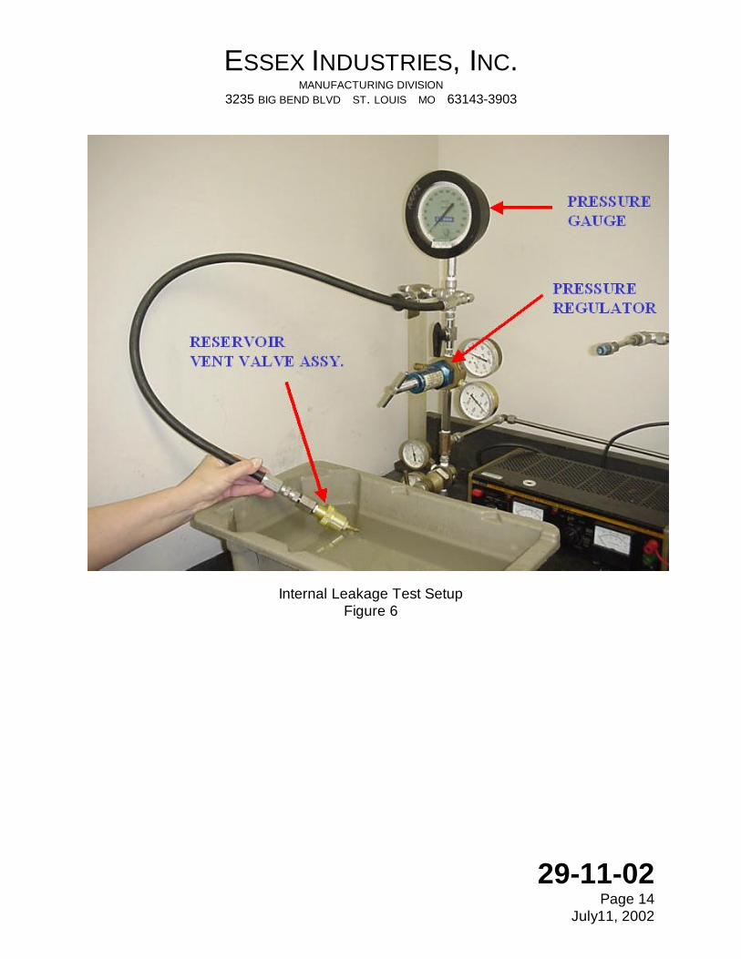
(1) Perform Internal Leakage Test as follows: (2) Install unit in suitable test fixture. See figure 6.
(3) Apply 50 psig air pressure to fixture inlet.
(4) Leakage shall not exceed 24 SCCM.
ESSEX INDUSTRIES, INC. MANUFACTURING DIVISION 3235 BIG BEND BLVD ST. LOUIS MO 63143-3903
29-11-02 Page 1
Jul 11, 2001
(5) With unit in “normal” mode, apply 25 psig liquid pressure to “res” port.

ESSEX INDUSTRIES, INC. MANUFACTURING DIVISION 3235 BIG BEND BLVD ST. LOUIS MO 63143-3903
29-11-02 Page 2
May 2, 1983
(6) Wait one (1) minute then measure leakage. (7) Leakage from “in” port shall not exceed 1 drop/minute of BMS 3-11 fluid. (8) No external wetting is allowed.
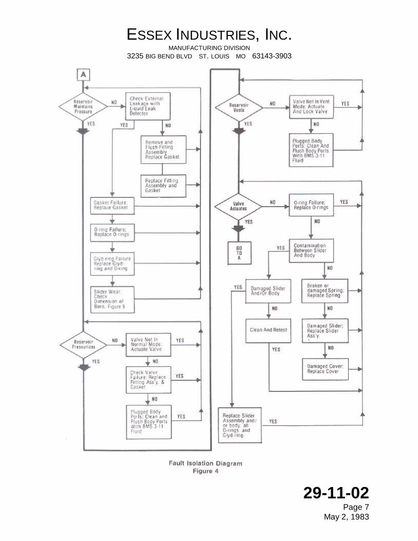
B. Troubleshooting (1) Use flow Chart Figure 4.
Figure 1

ESSEX INDUSTRIES, INC. MANUFACTURING DIVISION 3235 BIG BEND BLVD ST. LOUIS MO 63143-3903
29-11-02 Page 3
May 2, 1983
Figure 2 3. DISASSEMBLY
See testing and trouble shooting to determine extent of disassembly required for repair.
A. Disassemble the Reservoir Vent Valve as follows:
1. Remove the fitting (55) and discard gasket (50).
2. Remove the cover (45), spring (40), and washers (35).
3. Pull the slider assembly (25) off.
4. Remove and discard all O-rings, (10), (15), and Glyd-ring ( 20).

ESSEX INDUSTRIES, INC. MANUFACTURING DIVISION 3235 BIG BEND BLVD ST. LOUIS MO 63143-3903
29-11-02 Page 3
May 2, 1983
4. CLEANING
A. Immerse and agitate parts in Freon 113 or equivalent. Do not use

ESSEX INDUSTRIES, INC. MANUFACTURING DIVISION 3235 BIG BEND BLVD ST. LOUIS MO 63143-3903
29-11-02 Page 4
May 2, 1983
petroleum based solvent.
B. Blow dry parts with filtered, compressed air. C. Flush fitting assembly with BMS 3-11 fluid and shake dry. 5. CHECK
A. If seals have not been removed, inspect all seals for nicks. cuts. or scratches. Remove and discard any damaged seals (10), (15).
B. Inspect spring (40) for breakage or distortion. The spring should stand
vertically on either end within 5?. Loads shall be as specified in Figure 5 when measured with a suitable spring force gage. Replace spring (40) if damaged.
C. Inspect slider (25) inside diameter for scratches or gouges. The inside
diameter shall be as specified in Figure 5 when measured with a suitable micrometer. Replace slider assembly (25) if damaged or showing excessive wear.
D. Inspect slider (25) outside diameter and cover (45) for out-of-roundness
by measuring diameter at two points 90? apart. The two measurements shall not vary more than that specified in Figure 5. Replace slider assembly (25) and/or cover (45) if damaged.
E. Inspect threads on body (5) for visible damage. Replace body (5) if
damaged.
F. Inspect threads on fitting assembly (55) for visible damage. Replace fitting assembly (55) if damaged.
G. Inspect internal sealing surface of fitting (55) inlet for scoring and
damage. Replace if damaged. 6. REPAIR
A. Repairs consist of replacement of parts or assemblies.
B. All seals should be replaced whenever the valve is repaired. The following seals are affected:

ESSEX INDUSTRIES, INC. MANUFACTURING DIVISION 3235 BIG BEND BLVD ST. LOUIS MO 63143-3903
29-11-02 Page 5
May 2, 1983
Item (10), 0-rings Item (15), 0-rings Item (20), Glyd-rings Item (50), Gasket
All item numbers refer to IPL Figure 1.
FIGURE 3 7. ASSEMBLY
Assembly tools required, equivalent substitutes may be used for listed items. 11/16" Open End Wrench 13/16" Socket (Drive to Fit Torque Wrench) Torque Wrench, 0-250 in - Ibs.

ESSEX INDUSTRIES, INC. MANUFACTURING DIVISION 3235 BIG BEND BLVD ST. LOUIS MO 63143-3903
29-11-02 Page 5
May 2, 1983
BMS 3-11 Fluid Loctite Grade A

ESSEX INDUSTRIES, INC. MANUFACTURING DIVISION 3235 BIG BEND BLVD ST. LOUIS MO 63143-3903
29-11-02 Page 6
May 2, 1983
Essex Industries, Inc. Tools #EB 0091520200-1, Expander #EB 0091520200-2, Pusher #EB 0091520200-3, Sizer
A. Assemble the Reservoir Vent Valve as follows:
1. Place expander over body as shown in Figure 3. Lightly lubricate
all seals (10), (15), (20) with BMS 3-11 fluid. Place 0-ring (15) over expander and pusher. Place Glyd-ring (20) over expander and push into narrow groove using pusher. Remove expander and size Glyd-ring (20) with sizer as shown in Figure 3. Replace expander and install one 0-ring (10) into each remaining groove. Do not slide pusher past the Glyd-ring (20). Extreme care must be taken not to scratch or gouge the Glyd-ring.
2. Install scraper ring (30) into I.D. groove in slider (25).
3. Gently push slider assembly (25) with a twisting motion onto body
(5) until it bottoms out.
4. Place one washer (35) in cavity of slider assembly (25). Install spring (40) into the slider assembly (25).
5. Place the gasket (50) onto the fitting assembly (55). Apply one
drop of Loctite Grade A to threads. Slide cover (45) over the gasket (50). Place one washer (35) into the cavity of the cover (45).
6. Place cover (45) and fitting (55) over spring (40) and start fitting
threads into body (5). Slowly screw the fitting (55) into the body (5) to make certain the scraper (30) does not jam against the cover.
7. Actuate the slider several times to ensure proper operation of the
reservoir vent valve.
8. Torque fitting assembly (55) to body (5) to 140 +/- 10 in-lb.
9. If the valve is not to be installed immediately, seal in a plastic bag or install dust caps on fitting.
ESSEX INDUSTRIES, INC. MANUFACTURING DIVISION 3235 BIG BEND BLVD ST. LOUIS MO 63143-3903
29-11-02 Page 7
May 2, 1983

ESSEX INDUSTRIES, INC. MANUFACTURING DIVISION 3235 BIG BEND BLVD ST. LOUIS MO 63143-3903
29-11-02 Page 8
May 2, 1983
8. FITS AND CLEARANCES FIGURE 5
Spring (9) Parameters
Load @ 1.225 Length 5 lb +/- .5 lb Load @ .895 Length 5.8 lb +/- .5 lb Outside Diameter .975 +/- .010
Slider (30) Parameters
Inside Diameter .552/.551 Out-Of-Roundness .001
Cover (50) Parameter
Out-Of-Roundness .010
9. SPECIAL TOOLS
The following special tools are required for assembly of the reservoir vent valve:
EB #0091520200-1 - Expander EB #0091520200-2 - Pusher EB #0091520200-3 - Sizer

ESSEX INDUSTRIES, INC. MANUFACTURING DIVISION 3235 BIG BEND BLVD ST. LOUIS MO 63143-3903
29-11-02 Page 9
May 2, 1983
10. ILLUSTRATED PARTS LIST 1.0 INTRODUCTION
A. Purpose
(1) This section provides illustrations and parts breakdown of all parts of the assembly shown on the title page which can be disassembled, repaired or replaced and reassembled.
B. Explanation and Usage of Section
(1) Assembly Order Indenture System The indenture system used in the parts list shows the relationship of one part to another. For a given item, the number of the indentures depicts the relationship of the item to the associated next higher assembly as follows: 1 2 3
Assembly
Detail Parts for Assembly Subassemblies Attaching parts for Subassemblies Detail Parts for Subassemblies
(2) Effective Code (a) Reference letters (A, B, C, etc.) are assigned in the EFF CODE
column to each top assembly. The reference letter of the applicable top assembly is also shown in the EFF CODE column for each detail part and subassembly except that no reference letter is shown for detail parts and subassemblies used on all top assemblies.
(3) Quantity Per Assembly (a) The UNIT PER ASSEMBLY column shows the total number of units
required per assembly, per subassembly, as applicable. For bulk items, the letters AR indicate "as required." The RF indicate the item is listed for reference purposes.
(4) Parts Replacement Data

ESSEX INDUSTRIES, INC. MANUFACTURING DIVISION 3235 BIG BEND BLVD ST. LOUIS MO 63143-3903
29-11-02 Page 10
May 2, 1983
(a) The interchangeability relationship between parts, where applicable, is identified in the NOMENCLATURE column of the parts list. A list of the terms used to show interchangeability and their definition is as follows:
_____________________________________________________________________ Term Parts List Abbreviation Defintion Optional OPT This part is optional to and interchangeable
with other parts in the same item number variant group or other item number designated.
Superceded by SUPSD BY The part in the part number column is replaced
by and is not interchangeable with the item number shown in the notation.
Supercedes SUPSDS The part in the part number column replaces
and is not interchangeable with the item number shown in the notation.
Replaced by REPLD BY The part in the part number column is replaced
by and interchangeable with the item number shown in the notation.
Replaces REPLS The part in the part number column replaces
and is interchangeable with the item number shown in the notation.
(5) Service Bulletin Incorporation (a) Except as indicated below, assemblies, subassemblies, and detail
parts subject to modification, deletion, addition, or replacement by an issued service bulletin are annotated to show both pre- and post-service bulletin configuration. The term (PRE SB XXX) in the Nomenclature column designates the original configuration, and the term (POST SB XXXX) identifies assemblies and parts after the service bulletin modification has been completed.
(b) Subassemblies and detail parts used on assemblies bearing the
pre- or post-service bulletin notation will not carry the same notation themselves if the use code(s) assigned to them clearly reflect(s) their pre- or post-service bulletin status.

ESSEX INDUSTRIES, INC. MANUFACTURING DIVISION 3235 BIG BEND BLVD ST. LOUIS MO 63143-3903
29-11-02 Page 11
May 2, 1983
(c) Top assemblies subject to modification by a service bulletin without
assignment of a new part number (no production equivalent of the modified assembly) are not annotated with pre- or post-service bulletin information.
(d) If a subassembly or detail part is modified by a service bulletin
without a new part number being assigned, the original part number is listed with an alpha-variant item number and the term (POST SB XXXX). The effectivity code remains the same as for the pre-service bulletin configuration.
(6) Items Not Illustrated (a) Alpha variants A-Z (except I and O) are assigned to existing item
numbers when necessary to show:
1) Added items 2) Service bulletin modification 3) Configuration differences 4) Optional parts 5) Product improvement parts (non-service bulletin)
(b) Alpha variant item numbers are not shown on the exploded view
when the appearance and location of the alpha variant item is the same as the basic item.

ESSEX INDUSTRIES, INC. MANUFACTURING DIVISION 3235 BIG BEND BLVD ST. LOUIS MO 63143-3903
29-11-02 Page 12
May 2, 1983
FIG. AIRLINE NOMENCLATURE EFF UNITS ITEM PART NO. PART NO. 1 2 3 4 5 6 7 CODE PER
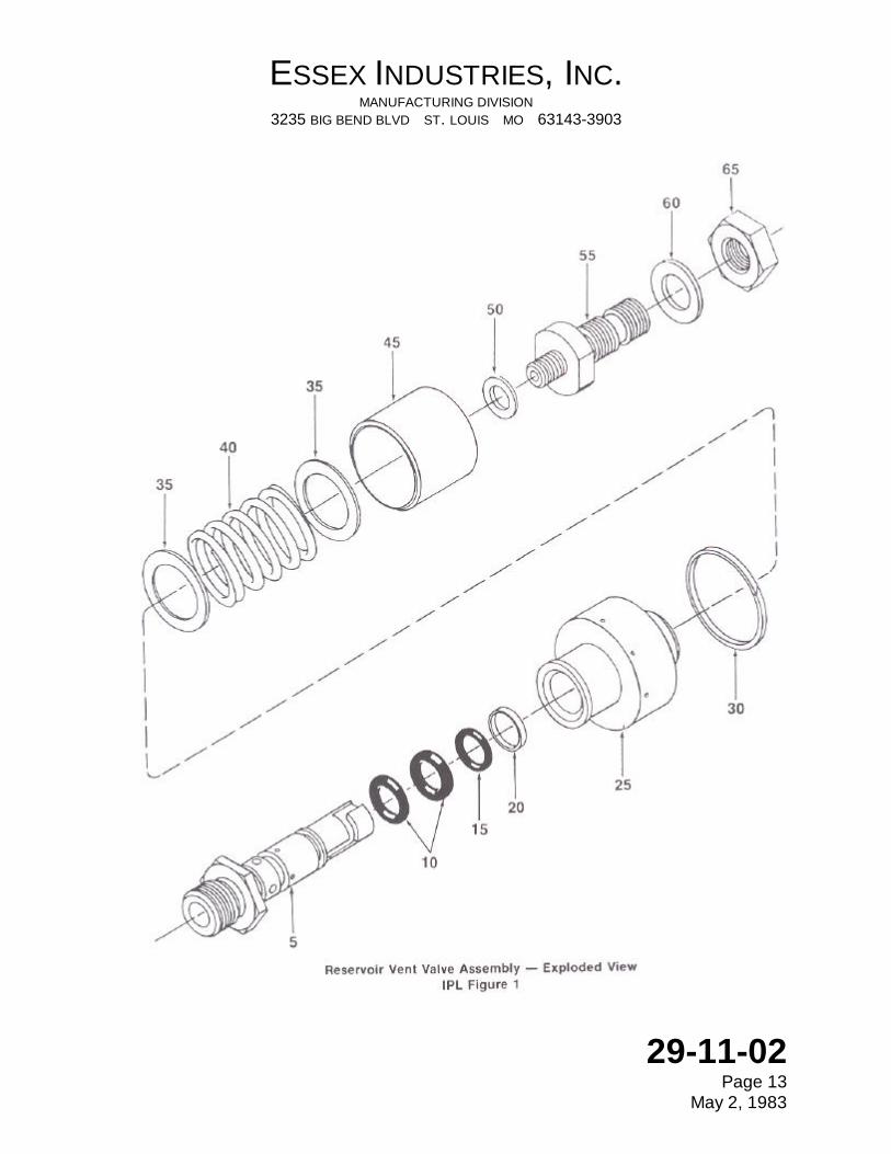
ASSY 1-1 0091520200-2 Valve-Reservoir Vent A RF 5 0091520201-2 *Body 1 10 NAS1611-110 *O-ring 2 15 NAS1611-012 *O-ring 1 20 S12068-013 *Glyd-Ring 1 25 0091520203-2 *Slider Assembly 1 30 MS28774-024 *Scraper 1 35 0091520207-1 *Washer 1 40 0091520208-1 *Spring 1 45 0091520204-1 *Cover 1 50 0091520205-1 *Gasket 1 55 00915202B1-1 *Fitting Assembly 1 60 AN960-716 *Washer 1 65 AN924-4S *Nut 1 -Items not illustrated
ESSEX INDUSTRIES, INC. MANUFACTURING DIVISION 3235 BIG BEND BLVD ST. LOUIS MO 63143-3903
29-11-02 Page 13
May 2, 1983
ESSEX INDUSTRIES, INC. MANUFACTURING DIVISION 3235 BIG BEND BLVD ST. LOUIS MO 63143-3903
29-11-02 Page 14
July11, 2002
Internal Leakage Test Setup Figure 6


![Service Manual OSPF OSPB, OSPC and Steering unit type ...1 Dust seal ring 2 Housing + spool + sleeve 3 Ball 8.5 mm [0.33 in] 4 Thread bushing 5 O-ring with kin-ring or Roto Glyd 7](https://static.fdocuments.us/doc/165x107/5f2a04225f75590f782b7aea/service-manual-ospf-ospb-ospc-and-steering-unit-type-1-dust-seal-ring-2-housing.jpg)