Reserve Systems, Inc. – Automatic Oil Level · PDF fileTO BURN, OR NOT TO BURN? Reserve...
12
INCREASE YOUR ENGINE LIFE UP TO 50% “The oil level is the magic!” ¾OIL LEVEL CONTROL: The only reliable level control for moving equipment. ¾OIL-TO-FUEL BLENDING: For large diesel engines of any make and model. ¾AUTOMATIC QUICK FILL: Convenient ground-level filling of oil service points. Reserve Systems, Inc. – Automatic Oil Level Systems 4040 MANLY ROAD ROSAMOND, CA . 93560 U.S.A TEL: 661-256-2275 FAX: 661-256-4979 EMAIL: [email protected] WEB: www.ReserveSystems.net Extend or eliminate oil changes. “Only with Reserve Systems!”
-
Upload
nguyennguyet -
Category
Documents
-
view
219 -
download
0
Transcript of Reserve Systems, Inc. – Automatic Oil Level · PDF fileTO BURN, OR NOT TO BURN? Reserve...

INCREASE YOUR ENGINE LIFE UP TO 50%
“The oil level is the magic!”
OIL LEVEL CONTROL: The only reliable level control for moving equipment.
OIL-TO-FUEL BLENDING: For large diesel engines of any make and model.
AUTOMATIC QUICK FILL: Convenient ground-level filling of oil service points.
Reserve Systems, Inc. – Automatic Oil Level Systems4040 MANLY ROAD ROSAMOND, CA . 93560 U.S.A
TEL: 661-256-2275 FAX: 661-256-4979 EMAIL: [email protected]: www.ReserveSystems.net
Extend or eliminate oil changes.
“Only with Reserve Systems!”

TO BURN, OR NOT TO BURN?Reserve Systems produces two types systems for engine oil level control and oil life extension. The first is the CLC circulating level control that continuously adjusts the engine oil level while circulating oil between the engine and a reserve tank, incorporating both volumes to increase the total working oil. The engine oil life is extended in proportion to the increased volume of oil. CLC systems have demonstrated that engine life between overhauls can be increased by 30% to 50%.
The second system is the CLC-M5 that has all the features of the CLC system and the additional function of metering engine oil into the engine fuel where it is burned as part of the fuel. Properly used, the CLC-M5 can virtually eliminate oil changes and oil disposal and, as with the CLC systems, increase the engine life by 30% to 50%. One user in California with a fleet of mining haultrucks equipped with CLC-M5 systems has demonstrated that engines can burn as much as 1 million gallons of fuel without oil changes or engine overhaul.
Both the CLC and CLC-M5 systems pay for themselves quickly in reduced down time and longer engine life.
The following pages describe both systems and their advantages, along with the choice of two different CLC pumping units and other components.
TABLE OF CONTENTS:Page 3: CLC System Description and Advantages
Page 4: CLC System Schematic with Operation Explanation
CLC Pumping Units: R2000 and R2000C – which to use.
Page 5: R2000 and R2000C Dimensional Drawings
Page 6: Reservetm CLC-M5 Level Control with Oil/Fuel Blending Description
Page 7: CLC-M5 System Schematic with Operation Explanation
Page 8: M5 Metering Pump
Page 9: Standard Horizontal and Vertical Tank Packages for CLC & CLC-M5 Systems
Page 10: AFC500 Automatic Fill Control for Ground-Level Filling of Tanks
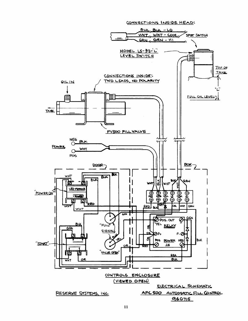
Page 11: AFC500 Electrical Schematic
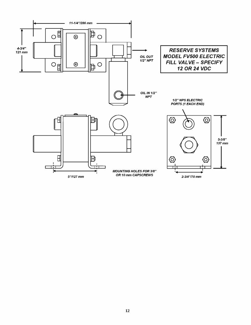
Page 12: FV500 Electric Fill Valve for AFC500
2

RESERVEtm MODEL CLC CIRCULATING OIL LEVEL CONTROL
OIL LEVEL CONTROL AND REDUCED SERVICINGReservetm Model CLC circulating level control is the only system available that actually adjusts oil levels. The CLC is constantly adding or removing oil, trying to improve an already good oil level. Overfills and under-fills are both avoided. All oil consumption shows at a reserve tank where it can be serviced on a convenient schedule.
Compare: Other available systems only add oil. Cold starts, changing demand and equipment motion all cause incorrect sensing of the oil level and unnecessary additions of oil. Add-only systems invariably overfill the equipment, causing aeration of the oil and progressive damage to the engine.
EXTENDED OIL CHANGE PERIODSIn the process of continuous adjustment of the engine oil level, CLC systems establish circulation of oil between the engine and a reserve tank. The volume of oil in the tank becomes part of the working oil for the engine. The larger volume of working oil slows the oil deterioration, allowing proportionally longer periods between oil changes.
As an example, if the chosen reserve tank size is equal to the normal engine oil volume, the volume of working oil is doubled, thus doubling the oil-change period. Because the oil spends much of its life in the reserve tank rather than in the engine, deterioration is often slowed more than proportionally. Using oil analysis as the guide, even longer oil-change extensions are possible.
In extreme or remote use where service is infrequent or very long oil change periods are needed, the a Reservetm system is your only choice. Reserve Systems has supplied systems designed to allow as much as six months of continuous operation without additions of oil or oil changes and without sacrificing clean oil or long engine life. No other system can match that.
INCREMENTAL OIL CHANGESWith a properly chosen CLC system, the time consuming traditional engine oil change can be eliminated, replaced by mini-changes. At a scheduled time of refilling the reserve tank, a quick evacuation and refill of the tank will freshen the engine oil in a fraction of the time required for a full change.
PROVEN PERFORMANCE AND PAYOFFThe CLC concept has proven itself in thousands of applications around the world to extend engine life by as much as 50%. More CLC systems are installed on engines in haultrucks and other mining equipment than all other makes of level control systems combined and are often installed as a backup for other makes of oil-burn systems. With tens of millions of hours of accumulated operation, Reservetm systems have proven themselves to be the only systems that can maintain exact oil levels, reduce servicing, extend or eliminate oil changes and extend time between engine overhauls. Our systems usually pay themselves off within one year and continue to pay year after year.
3

OPERATION:
The oil level is controlled and oil is circulated between the engine and a supply tank by two electrically driven pumps within a single pumping unit, the R2000.
Pump 1 draws from the running oil level within the engine sump. Any oil above this point is withdrawn and transferred to the supply tank. This lowers the level in the sump until air is drawn.
Air reaching the pumping unit activates Pump 2, which returns oil from the tank and raises the sump level until Pump 1 again draws air. Pump 2 then turns off.
The alternation between withdrawal and return of oil at the sump is continuous whenever the engine is running, thus controlling the level while circulating oil between the engine and the tank. The oil in the tank becomes part of the working oil for the engine. The larger volume of working oil slows engine oil deterioration at least in proportion to the increase.
CHOICE OF CLC PUMPING UNITS:
Reserve Systems CLC-R2000 systems are designed for engines of any horsepower using either Model R2000 or Model R2000C. Model R2000 is for general use where weather is rarely below freezing. Model R2000C is for use where weather is often below freezing. It has the ability to return extremely cold oil to the engine, pumping at a lower volume but higher pressure. The R2000C may be used in all weather conditions. When ordering pumping units or full systems, specify DC voltage (12, 24, or 72).
For dimensions and specifications, see the following page.
OIL/AIR RETURN TO
ENGINE
OIL/AIR REMOVAL
ENGINE
SUPPLY TANK
12
AIR RELIEF AND ANTI-SIPHON VALVE
R2000 PUMPING
UNIT
RUNNING OIL LEVEL
CLC SYSTEMS FOR ENGINE OIL LEVEL CONTROL AND CIRCULATION
4
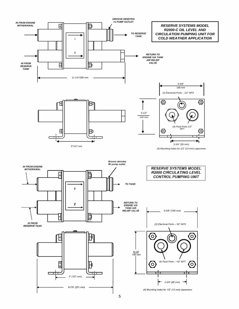
5”/127 mm
(2) Electrical Ports – 1/2” NPS
(4) Fluid Ports 1/2” NPT
3-3/4” (95 mm)
(4) Mounting holes for 1/2” (13 mm) capscrews
RESERVE SYSTEMS MODEL R2000-C OIL LEVEL AND
CIRCULATION PUMPING UNIT FOR COLD WEATHER APPLICATION
2
1
11-1/4”/286 mm
6-5/8”168 mm
5-1/2”
140 mm
IN FROM RESERVE
TANK
IN FROM ENGINE WITHDRAWAL
TO RESERVE TANK
RETURN TO ENGINE VIA TANK
AIR RELIEF VALVE
GROOVE DENOTES #1 PUMP OUTLET
5

RESERVEtm CLC-M5 LEVEL CONTROL WITH OIL/FUEL BLENDINGEliminate Oil Changes
CONTINUOUSLY ADJUSTS THE ENGINE OIL LEVEL:
As with CLC systems, Reserve Systems’ unique two-way level control continuously adds or removes oil as necessary to hold the most precise oil level of any available systems. Oil consumed or removed for blending reduces the oil level within the reserve tank where it is replaced with fresh oil at the time of servicing. Because the engine oil level is always correct, normal oil consumption is reduced.
INHERENTLY SAFE ON-BOARD OIL REMOVAL AND DISPOSAL:
With a Reserve system, the waste oil is removed from the safe running oil level within the engine, not from the pressure system. If the oil level should ever drop below that safe level, no more oil can be removed. The oil removal rate can be set at any desired level to meet any local requirements.
METERS SMALL INCREMENTS OF OIL FOR THOROUGH BLENDING:
Reserve oil/fuel blending systems introduce metered oil into the engine fuel system in increments of approximately 0.3 ml. This small amount of oil is added to the engine’s return fuel line near the engine end of the line. As the fuel flows back to the fuel tank, the oil blends thoroughly with the fuel to assure a homogeneous final blend that will burn cleanly and efficiently. Oil added to the fuel by this method in amounts up to 0.5% of fuel consumption has demonstrated that oil can be safely and cleanly recycled within the equipment while eliminating the hazards of traditional oil handling and disposal.
CLEAN OIL, CLEAN OPERATION AND REDUCED OIL CONSUMPTIONReserve Systems’ method of oil/fuel blending has demonstrated that waste oil can be disposed of safely and cleanly through burning as fuel within the engine while providing better, cleaner engine operation, clean engine oil, long engine life and reduction in waste to better protect the environment.
6
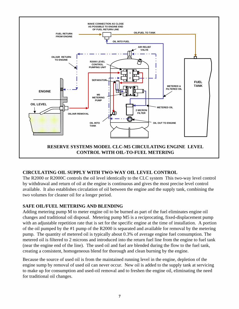
FUEL TANK
MAKE CONNECTION AS CLOSE AS POSSIBLE TO ENGINE END
OF FUEL RETURN LINE
OIL/AIR RETURN TO ENGINE
OIL/AIR REMOVAL
ENGINE
OIL LEVEL
2 MICRON FILTER
SEPARATOR
AIR RELIEF VALVE
RESERVE SYSTEMS MODEL CLC-M5 CIRCULATING ENGINE LEVEL CONTROL WITH OIL-TO-FUEL METERING
METERED OIL
METERED & FILTERED OIL
M5 METERING
PUMP
R2000 LEVEL CONTROL
PUMPING UNIT
1
2
OIL INTO TANK
OIL OUT TO ENGINE
OIL INTO FUEL
FUEL RETURN FROM ENGINE
OIL/FUEL TO TANK
CIRCULATING OIL SUPPLY WITH TWO-WAY OIL LEVEL CONTROLThe R2000 or R2000C controls the oil level identically to the CLC system This two-way level control by withdrawal and return of oil at the engine is continuous and gives the most precise level control available. It also establishes circulation of oil between the engine and the supply tank, combining the two volumes for cleaner oil for a longer period.
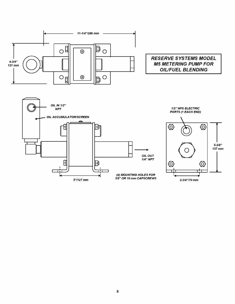
SAFE OIL/FUEL METERING AND BLENDINGAdding metering pump M to meter engine oil to be burned as part of the fuel eliminates engine oil changes and traditional oil disposal. Metering pump M5 is a reciprocating, fixed-displacement pump with an adjustable repetition rate that is set for the specific engine at the time of installation. A portion of the oil pumped by the #1 pump of the R2000 is separated and available for removal by the metering pump. The quantity of metered oil is typically about 0.3% of average engine fuel consumption. The metered oil is filtered to 2 microns and introduced into the return fuel line from the engine to fuel tank (near the engine end of the line). The used oil and fuel are blended during the flow to the fuel tank, creating a consistent, homogeneous blend for thorough and clean burning by the engine.
Because the source of used oil is from the maintained running level in the engine, depletion of the engine sump by removal of used oil can never occur. New oil is added to the supply tank at servicing to make up for consumption and used-oil removal and to freshen the engine oil, eliminating the need for traditional oil changes.
7
8
9

To Operate:
1. Remove the filler cap from the Reserve oil tank to prevent blowing during filling.
2. Energize the AFC systems by pulling out the top POWER ON switch.
3. Hook up the pressurized oil-fill hose to the quick-fill connector.
4. Turn on the pressure at the hose.
5. Press and release the lower START switch. If the tank is not full, the VALVE OPEN signal light will be on the oil will begin filling the tank through the FV500 fill valve mounted on the tank.
6. When the oil in the tank reaches the proper full level, a float switch mounted on the tank will signal back to the control box and the FV500 will close automatically to terminate filling. The FULL signal light will be illuminated.
7. After turning off the pressurized fill line, the START button should be pressed again for a couple of seconds to relieve any trapped pressure. The fill line can now be removed.
8. Turn off the AFC system by pushing in the POWER ON switch.
10
11
12