
RESEARCH_Zhang Yang_2015
11
Paper Abstracts: “Experimental Investigation on the Turbine Blade Platform Film Cooling Effected By the Flow Field” Journal of engineering thermophysics, 2011, Vol.32, No.6 P.941-944 An experimental investigation has been completed using PSP technique to study film cooling on a cooled turbine blade platform within a linear cascade. The effects of blowing ratio and inlet flow Reynolds number have been investigated and analyzed. The inlet flow Reynolds number is controlled to be Re=164476、226154、308392 and 359790, while the blowing ratio of the coolant varies from M=0.4 to1.4. The film cooling holes near the platform leading edge are inclined 45 deg to the platform surface and the rest are 30 deg. The result indicates that the film cooling effectiveness increases with the blowing ratio increasing, which is limited to the downstream half of the passage where the platform can be well protected by the coolant flow. In contrast, the film cooling effectiveness is reduced by increasing the blowing ratio near the leading edge region where the coolant tends to lift off the surface. The most effective blowing ratio at different inlet Reynolds number Re=164476、 226154、 308392、 359790 are M=1.2、 1.4、 1.4 and 0.8 respectively. When the blowing ratio is fixed, the best coolant coverage occurs at the largest inlet flow Reynolds number Re=359790. Fig. 1 Turbine blade cascades with LEDs Fig. 2 Film cooling effectiveness distribution with different blowing ratio (MFR=0.4/left, MFR=1.0, MFR=1.4/right) “Experimental Investigation about the Effects of Off-deign Condition on the Turbine Vane Endwall Film Cooling” Annual conference of engineering thermophysics 2010, Nanjing, China, Paper No. 102092 The effects of incidence angle on endwall film cooling in Hp turbine guide vanes were studied in this paper. The influence of the off-design condition was evaluated by comparison of the experimental data under different incidence angle varying from i=-15deg to i=+5deg. The film cooling effectiveness on the endwall surface was measured at the blowing ratio from MFR=0.4 to MFR=1.4. The original airfoil of GE-E3 Hp turbine guide vanes with an enlarging scale of 2.2 was used in the experiment. The inlet Mach number was Ma=0.1. The PSP (Pressure Sensitive Paint) technique was used to measure the film cooling effectiveness. A comparative analysis of three groups of incidence angle cases indicated the effects of incidence angle on endwall film cooling. The results showed that when the incidence angle was fixed at i=-15deg, i=0deg and i=+5deg respectively, the film cooling effectiveness increased first, but decreased then (or changed a little) with the blowing ratio increasing. The maximum film cooling effectiveness was measured at the blowing ratio MFR=1.2, illustrating that the coolant lifted off the surface at higher blowing ratio. When the blowing ratio was fixed, the endwall film cooling effectiveness decreased with the incidence angle increasing. The best cooling performance was observed at the incidence angle of i=-15deg. The influence of the cross flow on the endwall film cooling was obvious at i=+5deg. The cooling effectiveness near the pressure side decreased and then caused the decrease of film cooling effectiveness on the whole endwall. Through the comparative analysis between the laterally averaged film cooling effectiveness downstream the second and the third row of holes, a significant phenomenon was caught that coolant near the second row moved towards the pressure side while the injection moved in the opposite direction downstream the third row. At all test conditions, the film cooling effectiveness at downstream part of the endwall was higher than that of the upstream part at all test conditions in the experiment.
-
Upload
yang-zhang -
Category
Documents
-
view
52 -
download
0
Transcript of RESEARCH_Zhang Yang_2015
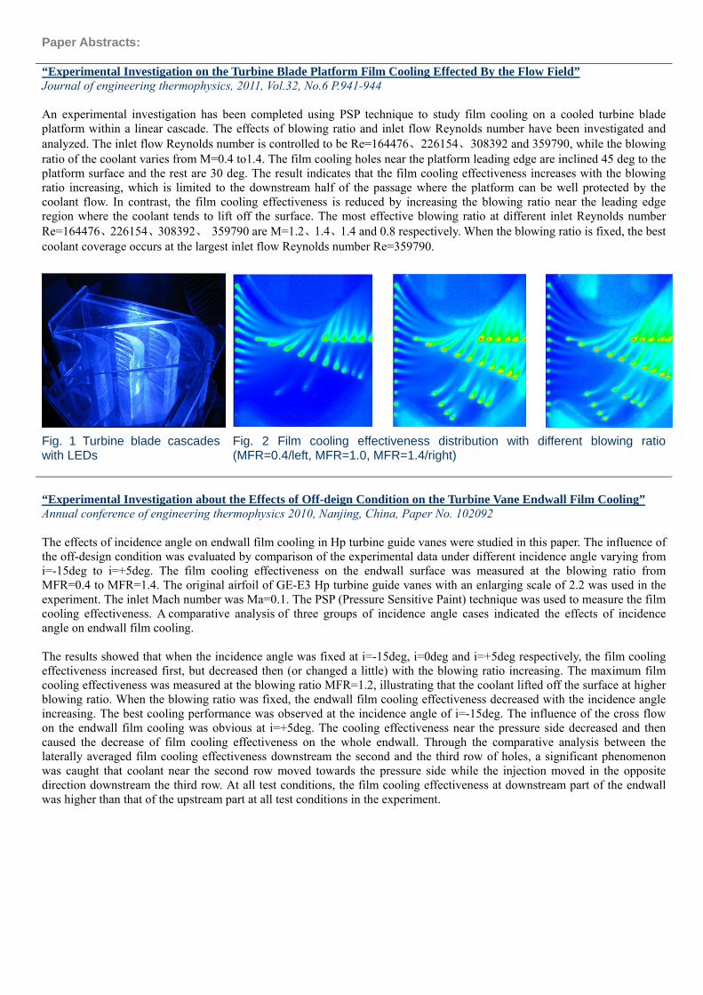
Paper Abstracts: “Experimental Investigation on the Turbine Blade Platform Film Cooling Effected By the Flow Field” Journal of engineering thermophysics, 2011, Vol.32, No.6 P.941-944 An experimental investigation has been completed using PSP technique to study film cooling on a cooled turbine blade platform within a linear cascade. The effects of blowing ratio and inlet flow Reynolds number have been investigated and analyzed. The inlet flow Reynolds number is controlled to be Re=164476、226154、308392 and 359790, while the blowing ratio of the coolant varies from M=0.4 to1.4. The film cooling holes near the platform leading edge are inclined 45 deg to the platform surface and the rest are 30 deg. The result indicates that the film cooling effectiveness increases with the blowing ratio increasing, which is limited to the downstream half of the passage where the platform can be well protected by the coolant flow. In contrast, the film cooling effectiveness is reduced by increasing the blowing ratio near the leading edge region where the coolant tends to lift off the surface. The most effective blowing ratio at different inlet Reynolds number Re=164476、226154、308392、 359790 are M=1.2、1.4、1.4 and 0.8 respectively. When the blowing ratio is fixed, the best coolant coverage occurs at the largest inlet flow Reynolds number Re=359790.
Fig. 1 Turbine blade cascades with LEDs
Fig. 2 Film cooling effectiveness distribution with different blowing ratio (MFR=0.4/left, MFR=1.0, MFR=1.4/right)
“Experimental Investigation about the Effects of Off-deign Condition on the Turbine Vane Endwall Film Cooling” Annual conference of engineering thermophysics 2010, Nanjing, China, Paper No. 102092 The effects of incidence angle on endwall film cooling in Hp turbine guide vanes were studied in this paper. The influence of the off-design condition was evaluated by comparison of the experimental data under different incidence angle varying from i=-15deg to i=+5deg. The film cooling effectiveness on the endwall surface was measured at the blowing ratio from MFR=0.4 to MFR=1.4. The original airfoil of GE-E3 Hp turbine guide vanes with an enlarging scale of 2.2 was used in the experiment. The inlet Mach number was Ma=0.1. The PSP (Pressure Sensitive Paint) technique was used to measure the film cooling effectiveness. A comparative analysis of three groups of incidence angle cases indicated the effects of incidence angle on endwall film cooling. The results showed that when the incidence angle was fixed at i=-15deg, i=0deg and i=+5deg respectively, the film cooling effectiveness increased first, but decreased then (or changed a little) with the blowing ratio increasing. The maximum film cooling effectiveness was measured at the blowing ratio MFR=1.2, illustrating that the coolant lifted off the surface at higher blowing ratio. When the blowing ratio was fixed, the endwall film cooling effectiveness decreased with the incidence angle increasing. The best cooling performance was observed at the incidence angle of i=-15deg. The influence of the cross flow on the endwall film cooling was obvious at i=+5deg. The cooling effectiveness near the pressure side decreased and then caused the decrease of film cooling effectiveness on the whole endwall. Through the comparative analysis between the laterally averaged film cooling effectiveness downstream the second and the third row of holes, a significant phenomenon was caught that coolant near the second row moved towards the pressure side while the injection moved in the opposite direction downstream the third row. At all test conditions, the film cooling effectiveness at downstream part of the endwall was higher than that of the upstream part at all test conditions in the experiment.

Fig. 3 Test rig with LEDs Fig. 4 Film cooling effectiveness distribution with different incidence angle
(i=+10deg/left, 0deg, -10deg/right)
“Film Cooling Effectiveness Distribution on First-Stage Vane Endwall With and Without Leading-Edge Fillets Part I:Effect of Leading Edge Geometry” ASME Turbo Expo 2011: Power for Land, Sea, and Air, Vancouver, Canada, ASME Paper No.GT2011-45427 The work is focused on the effect of leading edge airfoil geometry on endwall film cooling. Fillets placed at the junctions of the leading edge and the endwall are used in investigation. Three types of fillet profiles are tested, and the results are compared with baseline geometry without fillet. The design of the fillet is based on the suggestion by previous literature data indicating that the sharp fillet is effective in controlling the secondary flow. Three types of sharp slope fillet with the length to height ratio of 2.8, 1.2 and 0.5 are made using stereo lithography (SLA) and assessed in the experiment. Distributed with the approximately inviscid flow direction, four rows of compound angle laidback fan-shaped holes are arranged on the endwall to form full covered coolant film. The four rows of fanshaped holes are inclined 30 deg to the endwall surface and held an angle of 0, 30, 45 and 60 deg to axial direction respectively. The fanshaped holes have a lateral diffusion angle of 10 deg from the hole-centreline and a forward expansion angle of 10 deg to the endwall surface. The Reynolds number based on the axial chord and inlet velocity of the free-stream flow is 3.5×10⁵, and the testing is done in a four-blade cascade with low Mach number condition (0.1 at the inlet) while the blowing ratio of the coolant through the discrete holes varies from 0.4 to 1.2. The film-cooling effectiveness distributions are obtained using the PSP (pressure sensitive paint) technique, by which the effect of different fillet geometry on passage induced flow and coolant is shown. The present paper compares the film cooling effectiveness distributions in a baseline blade cascade with three similar blades with different leading edge by adding fillets. The results show that with blowing ratio increasing, the film cooling effectiveness increases on the endwall. For specific blowing ratio, the effects of leading edge geometries could be illustrated as follows. The baseline geometry provides the best film cooling performance near leading edge pressure side. As for the leading edge suction side, the best leading edge geometry depends on the blowing ratio. The longfillet is the more effective in controlling horseshoe vortex at low blowing ratio, but for the high blowing ratio shortfillet and mediumfillet are better.
Fig. 5 NGV cascades with long-fillet Fig. 6 Film cooling effectiveness distribution on the
endwall with different fillets “Film Cooling Effectiveness Distribution on First-Stage Vane Endwall With and Without Leading-Edge Fillets Part II:Effect of Incidence Angle” ASME Turbo Expo 2011: Power for Land, Sea, and Air, Vancouver, Canada, ASME Paper No.GT2011-45428

Using the leading edge airfoil fillet to reduce the aerodynamic loss and surface heat transfer has been proved effective, while the factor of film cooling has not been considered. The first part of the research indicates that the leading edge fillet could improve the film cooling effectiveness through controlling the secondary flow, while this conclusion is restricted to the design condition. The flow field at off-design condition is different from that of the design condition, especially for the structure of horseshoe vortex at the leading edge. It’s possible that the advantage of fillets is not reliable at positive or negative inlet flow angle conditions, which makes the investigation on endwall film cooling with leading edge modification at off-design condition necessary. This paper, which is the second part of a two-part series research investigating the effects of leading edge modification on endwall film cooling, is focused on the performance of fillets at off-design condition. The influence of incidence angle on film cooling effectiveness is studied on first-stage vane endwall with and without leading-edge fillets. A baseline configuration and three kinds of leading edge airfoil fillets are tested in a low speed four-blade cascade consisting of large scale model of the GE-E3 Nozzle Guide Vane (NGV). The results show that as the incidence angle varies from i=+10 deg to i=−10 deg, at low blowing ratio the film cooling effectiveness decreases near the leading edge suction side for all the leading edge geometries. However, this trend becomes opposite under high blowing ratio that the lowest film cooling effectiveness condition is at the incidence angle of i=+10 deg. Near the leading edge pressure side, the film cooling effectiveness increases as the incidence angle varies from i=+10 deg to i= −10 deg at all blowing ratios in the research. The change of incidence angle causes the peak of laterally averaged effectiveness in this region to shift upstream. The experimental results also indicate that the longfillet has the lowest sensitivity towards incidence angle. As for the main passage endwall, with the incidence angle changing form i=+10 deg to i=-10 deg the averaged film cooling effectiveness increases, while this trend will be eliminated by increasing the blowing ratio.
Fig. 7 Nozzle guide vane with Short-fillet Fig. 8 Film cooling effectiveness distribution at
different incidence angle “Turbine Endwall Film Cooling With Combustor-Turbine Interface Gap Leakage Flow: Effect of Incidence Angle” 10th International Symposium on Experimental and Computational Aerothermodynamics of Internal Flows - ISAIF10, Brussels, Belgium, ISAIF Paper No.114 The past research indicates that the combustor-turbine leakage flow could improve the film cooling effectiveness, while this result is obtained at the design condition. The flow field at off-design condition is different from that of the design condition, especially for the structure of horseshoe vortex at the leading edge. The change of the passage flow field at off-design condition will possibly weaken the cooling effectiveness of the combustor-turbine interface gap leakage flow. Near leading edge area the velocity direction will strongly influence the coolant injection behaviour, which makes it necessary to investigate the leakage flow cooling performance at off-design conditions.This paper is focused on the performance of combustor-turbine leakage flow at off-design condition. The influence of incidence angle on film cooling effectiveness is studied on first-stage vane endwall with combustor-turbine interface slot. A baseline slot configuration is tested in a low speed four-blade cascade consisting of large scale model of the GE-E3 Nozzle Guide Vane (NGV). The slot has a forward expansion angle of 30 deg to the endwall surface. The Reynolds number based on the axial chord and inlet velocity of the free-stream flow is 3.5×10⁵, and the testing is done in a four-blade cascade with low Mach number condition (0.1 at the inlet) while the mass flow ratio of the coolant through the interface gap varies from 0.5% to 2.0%. The film-cooling effectiveness distributions are obtained using the PSP (pressure sensitive paint) technique. The results show that with blowing ratio increasing, the film cooling effectiveness increases on the endwall. As the incidence angle varies from i=+10 deg to i=-10 deg, at low blowing ratio the film cooling effectiveness decreases near the leading edge suction side. As for the main passage

endwall, with the incidence angle changing form i=+10 deg to i=-10 deg the averaged film cooling effectiveness changes slightly, while this trend will be eliminated by increasing the blowing ratio.
purge Ms=0.5% i= 0degZG
/P
XG
/Cax
-0.2 0 0.2 0.4 0.6 0.8
-1.2
-1
-0.8
-0.6
-0.4
-0.2
0
purge Ms=1.0% i= 0degZG
/P
XG
/Cax
-0.2 0 0.2 0.4 0.6 0.8
-1.2
-1
-0.8
-0.6
-0.4
-0.2
0
purge Ms=1.5% i= 0degZG
/P
XG
/Cax
-0.2 0 0.2 0.4 0.6 0.8
-1.2
-1
-0.8
-0.6
-0.4
-0.2
0
Fig. 9 NGV cascades with upstream slot Fig. 10 Film cooling effectiveness distribution with different mass flow
ratio (M=0.5%, 1.0%, 1.5%)
“The Influence of Periodic Unsteady Wakes on Endwall Film Cooling with Combustor-Turbine Interface Gap Leakage Flow” International Gas Turbine Congress 2011-IGTC'11, Osaka, Japan, IGTC Paper No.IGTC2011-0126 Using the combustor-turbine leakage flow to prevent the hot gases entering the interface slot has been proved effective, while the function of the leakage flow as coolant has not been investigated sufficiently, especially under unsteady inflow condition. In order to close the gap in knowledge concerning the influence of periodic unsteady inflow conditions on the mixing process of film cooling jets from the combustor-turbine slot, the film cooling effectiveness in a linear large scale high pressure turbine cascade is measured using Pressure Sensitive Paint (PSP). This paper is focused on the performance of combustor-turbine leakage flow affected by the upstream periodic wakes. The influence of periodic wakes on film cooling effectiveness is studied on a first-stage vane endwall with combustor-turbine interface gap. The periodic impinging wakes are generated by a wake generator consisting of moving bars upstream of the cascade inlet plane. A baseline slot configuration is tested in a low speed five-blade cascade consisting of large scale model of the LS 89 Nozzle Guide Vane (NGV). The slot has a forward expansion angle of 30 deg to the endwall surface. The Reynolds number based on the axial chord and exit velocity of the free-stream flow is 6.34×10⁵, and the testing is performed with low Mach number condition (0.06 at the inlet) while the mass flow ratio of the coolant through the interface gap varies from 0.3% to 0.7%. The film-cooling effectiveness distributions are obtained using the PSP (pressure sensitive paint) technique. The results show that with blowing ratio increasing, the film cooling effectiveness increases on the endwall. As the frequency of the passing wakes varies from 0hz, 25hz to 50hz, the film cooling effectiveness decreases in the main passage endwall, especially near the leading edge suction side while the difference between low and high frequency condition is not apparent.
purge M=0.3% f=25hz
ZG
/P
XG
/Cax
-0.19 0.01 0.21 0.41 0.61 0.81 1.0
-1
-0.8
-0.6
-0.4
-0.2
0
purge M=0.3% f=0hz
ZG
/P
XG
/Cax
-0.19 0.01 0.21 0.41 0.61 0.81 1.0
-1
-0.8
-0.6
-0.4
-0.2
0
Fig. 11 Schematic of the moving bar test rig Fig. 12 Film cooling effectiveness distribution with and without
upstream periodic wakes
“Endwall Film Cooling with Curving Slot Leakage Flow” Annual conference of engineering thermophysics 2011, Wuhan, China, Paper No. 112079 To cool the endwall with the combustor-turbine leakage flow has been proved to be feasible, while the search results are restricted to simple straight slot. The shape of the upstream slot could possibly change the covering skill of the coolant and
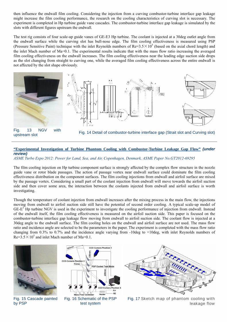
then influence the endwall film cooling. Considering the injection from a curving combustor-turbine interface gap leakage might increase the film cooling performance, the research on the cooling characteristics of curving slot is necessary. The experiment is completed in Hp turbine guide vane cascades. The combustor-turbine interface gap leakage is simulated by the slots with different figures upstream the endwall. The test rig consists of four scale-up guide vanes of GE-E3 Hp turbine. The coolant is injected at a 30deg outlet angle from the endwall surface while the curving slot has bull-nose edge. The film cooling effectiveness is measured using PSP (Pressure Sensitive Paint) technique with the inlet Reynolds numbers of Re=3.5×10⁵ (based on the axial chord length) and the inlet Mach number of Ma=0.1. The experimental results indicate that with the mass flow ratio increasing the averaged film cooling effectiveness on the endwall increases. The film cooling effectiveness near the leading edge suction side drops as the slot changing from straight to curving one, while the averaged film cooling effectiveness across the entire endwall is not affected by the slot shape obviously.
Fig. 13 NGV with upstream slot
Fig. 14 Detail of combustor-turbine interface gap (Strait slot and Curving slot)
“Experimental Investigation of Turbine Phantom Cooling with Combustor-Turbine Leakage Gap Flow” (under review) ASME Turbo Expo 2012: Power for Land, Sea, and Air, Copenhagen, Denmark, ASME Paper No.GT2012-69295 The film cooling injection on Hp turbine component surface is strongly affected by the complex flow structure in the nozzle guide vane or rotor blade passages. The action of passage vortex near endwall surface could dominate the film cooling effectiveness distribution on the component surfaces. The film cooling injections from endwall and airfoil surface are mixed by the passage vortex. Considering a small part of the coolant injection from endwall will move towards the airfoil suction side and then cover some area, the interaction between the coolants injected from endwall and airfoil surface is worth investigating. Though the temperature of coolant injection from endwall increases after the mixing process in the main flow, the injections moving from endwall to airfoil suction side still have the potential of second order cooling. A typical scale-up model of GE-E3 Hp turbine NGV is used in the experiment to investigate the cooling performance of injection from endwall. Instead of the endwall itself, the film cooling effectiveness is measured on the airfoil suction side. This paper is focused on the combustor-turbine interface gap leakage flow moving from endwall to airfoil suction side. The coolant flow is injected at a 30deg angle to the endwall surface. The film cooling holes on the endwall and airfoil surface are not used. The mass flow ratio and incidence angle are selected to be the parameters in the paper. The experiment is completed with the mass flow ratio changing from 0.3% to 0.7% and the incidence angle varying from -10deg to +10deg, with inlet Reynolds numbers of Re=3.5×10⁵ and inlet Mach number of Ma=0.1.
Fig. 15 Cascade painted by PSP
Fig. 16 Schematic of the PSP test system
Fig. 17 Sketch map of phantom cooling with leakage flow
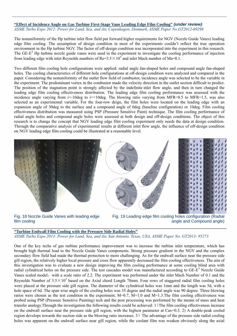
“Effect of Incidence Angle on Gas Turbine First-Stage Vane Leading Edge Film Cooling” (under review) ASME Turbo Expo 2012: Power for Land, Sea, and Air, Copenhagen, Denmark, ASME Paper No.GT2012-69298 The nonuniformity of the Hp turbine inlet flow field put forward higher requirements for NGV (Nozzle Guide Vanes) leading edge film cooling. The assumption of design condition in most of the experiments couldn’t reflect the true operation environment in the Hp turbine NGV. The factor of off-design condition was incorporated into the experiment in this research. The GE-E3 Hp turbine nozzle guide vanes were used in the experiment to investigate the cooling performance of injection from leading edge with inlet Reynolds numbers of Re=3.5×10⁵ and inlet Mach number of Ma=0.1. Two different film cooling hole configurations were applied: radial angle fan-shaped holes and compound angle fan-shaped holes. The cooling characteristics of different hole configurations at off-design condition were analyzed and compared in the paper. Considering the nonuniformity of the outlet flow field of combustor, incidence angle was selected to be the variable in the experiment. The predominant vortex in the combustor made the velocity direction in the outlet section difficult to predict. The position of the stagnation point is strongly affected by the indefinite inlet flow angle, and then in turn changed the leading edge film cooling effectiveness distribution. The leading edge film cooling performance was assessed with the incidence angle varying from i=-10deg to i=+10deg. The blowing ratio varying from MFR=0.5 to MFR=1.5, was also selected as an experimental variable. For the four-row deign, the film holes were located on the leading edge with an expansion angle of 30deg to the surface and a compound angle of 0deg (baseline configuration) or 10deg. Film cooling effectiveness distribution was measured using PSP (Pressure Sensitive Paint) technique. The film cooling performance of radial angle holes and compound angle holes were assessed at both design and off-design conditions. The object of this research is to change the concept that NGV leading edge film cooling experiment only needs the data at design condition. Through the comparative analysis of experimental results at different inlet flow angle, the influence of off-design condition on NGV leading edge film cooling could be illustrated at a reasonable level.
Fig. 18 Nozzle Guide Vanes with leading edge film cooling
Fig. 19 Leading edge film cooling holes configuration (Radial angle and Compound angle)
“Turbine Endwall Film Cooling with the Pressure Side Radial Holes” ASME Turbo Expo 2013: Power for Land, Sea, and Air, San Antonio, Texas, USA, ASME Paper No. GT2013- 95273 One of the key techs of gas turbine performance improvement was to increase the turbine inlet temperature, which has brought high thermal load to the Nozzle Guide Vanes components. Strong pressure gradient in the NGV and the complex secondary flow field had made the thermal protection to more challenging. As for the endwall surface near the pressure side gill region, the relatively higher local pressure and cross flow apparently decreased the film cooling effectiveness. The aim of this investigation was to evaluate a new design improving the film cooling performance at some cooling blind area with radial cylindrical holes on the pressure side. The test cascades model was manufactured according to GE-E3 Nozzle Guide Vanes scaled model,with a scale ratio of 2.2. The experiment was performed under the inlet Mach Number of 0.1 and the Reynolds Number of 3.5×10⁵ based on the Axial chord Length 78mm. Four rows of staggered radial film cooling holes were placed at the pressure side gill region. The diameter of the cylindrical holes was 1mm and the length was 5d, with a hole space of 6d. The span wise angle of the cooling holes was 35 degree and the radial angle was 90 degree. Three blowing ratios were chosen as the test condition in the experiment, M=0.7, M=1.0 and M=1.3.The film cooling effectiveness was probed using PSP (Pressure Sensitive Painting) tech and the post processing was performed by the means of mass and heat transfer analogy.Through the investigation the following results could be achieved: 1)The film cooling effectiveness increase on the endwall surface near the pressure side gill region, with the highest parameter at Cax=0.3. 2) A double-peak cooled region develops towards the suction side as the blowing ratio increases. 3)The advantage of the pressure side radial cooling holes was apparent on the endwall surface near gill region, while the coolant film was weaken obviously along the axial
chord at low blowing ratio. The influence of the pressure film cooling could only be detected at the downstream part of the endwall at higher blowing ratio.
Baseline M=0.7 i= 0deg
Z/Z P
X/Cax
1 2
3
-0.1 0.1 0.3 0.5 0.7 0.9
-0.2
0
0.2
0.4
0.6
0.8
1
1.2
0 0.2 0.4 0.6
PsCooling M=0.7 i= 0deg
Z/Z P
X/Cax
1 2
3
-0.1 0.1 0.3 0.5 0.7 0.9
-0.2
0
0.2
0.4
0.6
0.8
1
1.2
0 0.2 0.4 0.6
Fig. 20 The radial cylindrical holes on the pressure side and the fan shaped holes on the endwall
Fig.21 Film cooling effectiveness distribution on endwall
(the blowing ratio is 0.7, with and without pressure side injection)
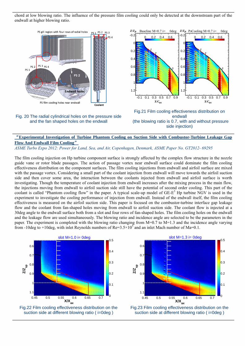
“Experimental Investigation of Turbine Phantom Cooling on Suction Side with Combustor-Turbine Leakage Gap Flow And Endwall Film Cooling” ASME Turbo Expo 2012: Power for Land, Sea, and Air, Copenhagen, Denmark, ASME Paper No. GT2012- 69295 The film cooling injection on Hp turbine component surface is strongly affected by the complex flow structure in the nozzle guide vane or rotor blade passages. The action of passage vortex near endwall surface could dominate the film cooling effectiveness distribution on the component surfaces. The film cooling injections from endwall and airfoil surface are mixed with the passage vortex. Considering a small part of the coolant injection from endwall will move towards the airfoil suction side and then cover some area, the interaction between the coolants injected from endwall and airfoil surface is worth investigating. Though the temperature of coolant injection from endwall increases after the mixing process in the main flow, the injections moving from endwall to airfoil suction side still have the potential of second order cooling. This part of the coolant is called “Phantom cooling flow” in the paper. A typical scale-up model of GE-E3 Hp turbine NGV is used in the experiment to investigate the cooling performance of injection from endwall. Instead of the endwall itself, the film cooling effectiveness is measured on the airfoil suction side. This paper is focused on the combustor-turbine interface gap leakage flow and the coolant from fan-shaped holes moving from endwall to airfoil suction side. The coolant flow is injected at a 30deg angle to the endwall surface both from a slot and four rows of fan-shaped holes. The film cooling holes on the endwall and the leakage flow are used simultaneously. The blowing ratio and incidence angle are selected to be the parameters in the paper. The experiment is completed with the blowing ratio changing from M=0.7 to M=1.3 and the incidence angle varying from -10deg to +10deg, with inlet Reynolds numbers of Re=3.5×10⁵ and an inlet Mach number of Ma=0.1.
slot M=1.0 i= 0deg
Z/Z
sp
X/Xax
0.45 0.5 0.55 0.6 0.65 0.7
0.6
0.7
0.8
0.9
1
1.10
0.1
0.2
0.3
0.4
0.5slot M=1.3 i= 0deg
Z/Z
sp
X/Xax
0.45 0.5 0.55 0.6 0.65 0.7
0.6
0.7
0.8
0.9
1
1.10
0.1
0.2
0.3
0.4
0.5
Fig.22 Film cooling effectiveness distribution on the suction side at different blowing ratio ( i=0deg )
Fig.23 Film cooling effectiveness distribution on the suction side at different blowing ratio ( i=0deg )

Effect of Incidence Angle on Gas Turbine First-Stage Nozzle Guide Vane Leading Edge And Gill Region Film Cooling ASME Turbo Expo 2012: Power for Land, Sea, and Air, Copenhagen, Denmark, ASME Paper No. GT2012- 69298 The nonuniformity of the Hp turbine inlet flow field put forward higher requirements for NGV (Nozzle Guide Vanes) leading edge and gill region film cooling. The assumption of design condition in most of the experiments couldn’t reflect the true operation environment in the Hp turbine NGV. The factor of off-design condition was incorporated into the experiment in this research. The GE-E3 Hp turbine nozzle guide vanes were used in the experiment to investigate the cooling performance of injection from leading edge and gill region with inlet Reynolds numbers of Re=3.5×10⁵ and inlet Mach number of Ma=0.1. The compound angle fan-shaped film cooling hole configuration was applied.
The cooling characteristics at off-design condition were analyzed and compared in the paper. The leading edge and gill region film cooling performance was assessed with the incidence angle varying from i=-10deg to i=+10deg. The blowing ratio varying from M=0.7 to M=1.3, was also selected as an experimental variable. Film cooling effectiveness distribution was measured using PSP (Pressure Sensitive Paint) technique. The film cooling performance of the compound angle fan-shaped holes was assessed at both design and off-design conditions. The object of this research is to change the concept that NGV leading edge film cooling experiment only needs the data at design condition. Through the comparative analysis of experimental results at different inlet flow angle, the influence of off-design condition on NGV leading edge and gill region film cooling could be illustrated at a reasonable level.
compound M=0.7 i= 0deg
Z/Z
sp
X/Xax
0 0.1 0.2 0.3 0.4
0
0.2
0.4
0.6
0.8
1
0
0.1
0.2
0.3
0.4
0.5
0.6
0.7
Fig.24 Compound angle film cooling holes configuration on leading edge and gill region (compared with radial
holes)
Fig.25 Film cooling effectiveness distribution on leading edge and pressure side (the blowing ratio is 0.7
and the incidence angle is 0deg)
Turbine Endwall Film Cooling With Combustor-Turbine Interface Gap Leakage Flow: Effect of Incidence Angle Journal of Thermal Science Vol.22, No.2 (2013) 1−10 This paper is focused on the film cooling performance of combustor-turbine leakage flow at off-design condition. The influence of incidence angle on film cooling effectiveness on first-stage vane endwall with combustor-turbine interface slot is studied. A baseline slot configuration is tested in a low speed four-blade cascade comprising a large-scale model of the GE-E3 Nozzle Guide Vane (NGV). The slot has a forward expansion angle of 30 deg to the endwall surface. The Reynolds number based on the axial chord and inlet velocity of the free-stream flow is 3.5 × 10⁵ and the testing is done in a four-blade cascade with low Mach number condition (0.1 at the inlet). The blowing ratio of the coolant through the interface gap varies from M = 0.1 to M = 0.3, while the blowing ratio varies from M = 0.7 to M = 1.3 for the endwall film cooling holes. The film-cooling effectiveness distributions are obtained using the pressure sensitive paint (PSP) technique. The results show that with an increasing blowing ratio the film-cooling effectiveness increases on the endwall. As the incidence angle varies from i = +10 deg to i = -10 deg, at low blowing ratio, the averaged film-cooling effectiveness changes slightly near the leading edge suction side area. The case of i = +10 deg has better film-cooling performance at the downstream part of this region where the axial chord is between 0.15 and 0.25. However, the disadvantage of positive incidence appears when the blowing ratio increases, especially at the upstream part of near suction side region where the axial chord is between 0 and 0.15. On the main passage endwall surface, as the incidence angle changes from i = +10 deg to i = -10 deg, the averaged film-cooling effectiveness changes slightly and the negative incidence appears to be more effective for the downstream part film cooling of the endwall surface where the axial chord is between 0.6 and 0.8.
slot M=0.7 i= 0deg
Z/Z P
X/C ax
1
2
3
-0.2 0 0.2 0.4 0.6 0.8
0
0.2
0.4
0.6
0.8
1
1.2 0 0.2 0.4 0.6 0.8
slot M=0.7 i= +10deg
Z/Z P
X/Cax
1
2
3
-0.2 0 0.2 0.4 0.6 0.8
0
0.2
0.4
0.6
0.8
1
1.2 0 0.2 0.4 0.6 0.8
slot M=0.7 i= -10deg
Z/Z P
X/Cax
1
2
3
-0.2 0 0.2 0.4 0.6 0.8
0
0.2
0.4
0.6
0.8
1
1.2 0 0.2 0.4 0.6 0.8
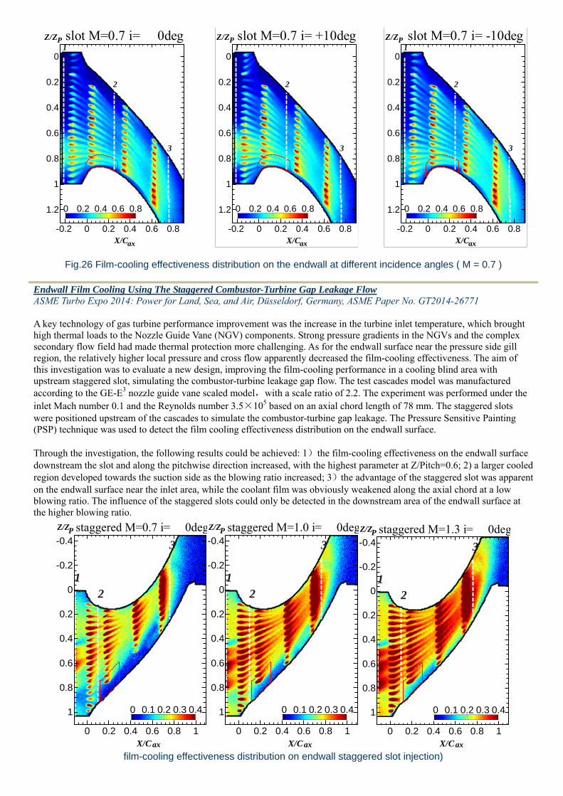
Fig.26 Film-cooling effectiveness distribution on the endwall at different incidence angles ( M = 0.7 )
Endwall Film Cooling Using The Staggered Combustor-Turbine Gap Leakage Flow ASME Turbo Expo 2014: Power for Land, Sea, and Air, Düsseldorf, Germany, ASME Paper No. GT2014-26771 A key technology of gas turbine performance improvement was the increase in the turbine inlet temperature, which brought high thermal loads to the Nozzle Guide Vane (NGV) components. Strong pressure gradients in the NGVs and the complex secondary flow field had made thermal protection more challenging. As for the endwall surface near the pressure side gill region, the relatively higher local pressure and cross flow apparently decreased the film-cooling effectiveness. The aim of this investigation was to evaluate a new design, improving the film-cooling performance in a cooling blind area with upstream staggered slot, simulating the combustor-turbine leakage gap flow. The test cascades model was manufactured according to the GE-E3 nozzle guide vane scaled model,with a scale ratio of 2.2. The experiment was performed under the inlet Mach number 0.1 and the Reynolds number 3.5×10⁵ based on an axial chord length of 78 mm. The staggered slots were positioned upstream of the cascades to simulate the combustor-turbine gap leakage. The Pressure Sensitive Painting (PSP) technique was used to detect the film cooling effectiveness distribution on the endwall surface. Through the investigation, the following results could be achieved: 1)the film-cooling effectiveness on the endwall surface downstream the slot and along the pitchwise direction increased, with the highest parameter at Z/Pitch=0.6; 2) a larger cooled region developed towards the suction side as the blowing ratio increased; 3)the advantage of the staggered slot was apparent on the endwall surface near the inlet area, while the coolant film was obviously weakened along the axial chord at a low blowing ratio. The influence of the staggered slots could only be detected in the downstream area of the endwall surface at the higher blowing ratio.
staggered M=0.7 i= 0deg
Z/Z P
X/C ax
1 2
3
0 0.2 0.4 0.6 0.8 1
-0.4
-0.2
0
0.2
0.4
0.6
0.8
1 0 0.1 0.2 0.3 0.4
staggered M=1.0 i= 0deg
Z/Z P
X/C ax
1 2
3
0 0.2 0.4 0.6 0.8 1
-0.4
-0.2
0
0.2
0.4
0.6
0.8
1 0 0.1 0.2 0.3 0.4
staggered M=1.3 i= 0deg
Z/Z P
X/C ax
1 2
3
0 0.2 0.4 0.6 0.8 1
-0.4
-0.2
0
0.2
0.4
0.6
0.8
1 0 0.1 0.2 0.3 0.4
film-cooling effectiveness distribution on endwall staggered slot injection)

Experimental Investigation Of Turbine Phantom Cooling On Endwall With Trailing Edge Discharge Flow ASME Turbo Expo 2014: Power for Land, Sea, and Air, Düsseldorf, Germany, ASME Paper No. GT2014-26781 The film cooling ejection on High Pressure (Hp) turbine component surface is strongly affected by the complex flow structure in the nozzle guide vane or rotor blade passages. The action of secondary flow in the main passage could dominate the film cooling effectiveness distribution on the component surfaces. The film cooling ejections from endwall and airfoil trailing edge are mixed by the secondary flow. Considering a small part of the coolant ejection from trailing edge discharge flow will move from the airfoil trailing edge pressure side to endwall downstream and then cover some area, the interaction between the coolants injected from endwall and airfoil trailing edge is worth investigating. Though the temperature of coolant discharge flow from trailing edge increases after the mixing process in the internal cooling procedure, the ejections moving from airfoil to endwall still have the potential of second order cooling. This part of the coolant is called “Phantom cooling flow” in the paper. A typical scale-up model of Hp turbine NGV is used in the experiment to investigate the cooling performance of ejection from trailing edge. Instead of the airfoil trailing edge platform itself, the film cooling effectiveness is measured on the downstream part of the endwall. This paper is focused on the trailing edge discharge flow with compound angle effects and the coolant from discharge holes moving from trailing edge to endwall surface. The coolant flow is injected from the straight discharge holes with a compound angle of 15deg and 45deg respectively. The film cooling holes on the endwall are used simultaneously to investigate the combined effects. The blowing ratio and different configurations of compound angle holes are selected to be the changing parameters in the paper. The experiment is completed with the blowing ratio changing from M=0.7 to M=1.3 and the compound angle is introduced to the entire row of trailing edge discharge holes (full span), with inlet Reynolds numbers of Re=3.5×10⁵ and an inlet Mach number of Ma=0.1
trailing45 M=1.3 i= 0deg
Z/Z P
X/C ax
1
2
3
0.9 1 1.1
-0.2
-0.1
00 0.2 0.4 0.6
trailing45 M=1.0 i= 0deg
Z/Z P
X/C ax
1
2
3
0.9 1 1.1
-0.2
-0.1
00 0.2 0.4 0.6
trailing45 M=0.7 i= 0deg
Z/Z P
X/C ax
1
2
3
0.9 1 1.1
-0.2
-0.1
00 0.2 0.4 0.6
trailing edge discharge hole configuration (with inner stucture of coolant supply channel)

Experimental Investigation On Nonperiodic Endwall Film Cooling In Neighboring Passages with Upstream Rotating Flow ASME Turbo Expo 2014: Power for Land, Sea, and Air, Düsseldorf, Germany, ASME Paper No. GT2014-26824 The distribution of film-cooling holes is considered to be the same between neighboring high pressure turbine passages in most cascade experiments. Because of the difference in accounts of combustors and vanes, however, the flow fields of neighboring passages are completely different. The secondary flow, especially the passage vortex, is dominated by the upstream inlet rotating flow whose relative flow direction is the reverse between the neighboring vane passages. Specific rotating directions introduce new challenges in film-cooling design. The present experiment compares three groups of endwall film-cooling with anticlockwise rotating flow inlets at different clocking positions, and the film-cooling effect is analysed to investigate the effects of inlet rotating flow. The inlet flow condition of neighboring passages is simulated by switching the position of the swirler by means of which rotating inlet flow conditions in different positions are achieved. The GE-E3 airfoil is used in the cascades, with a scaled-up factor of 2.2. The inlet Reynolds number is 3.5×10⁵ and the Mach number is 0.1. The effects of the blowing ratio and relative positions of the swirler are investigated in the experiment. Adiabatic film-cooling effectiveness is probed by using pressure-sensitive painting (PSP). The coolant is simulated by nitrogen by which a density ratio of around 1.0 can be achieved. Fan-shaped film-cooling holes are introduced into the endwall surface as well as trailing edge discharge holes. The cooling performance of the combustor-turbine gap leakage flow is also considered simultaneously. Conclusions are as follows: (1) the anticlockwise direction of rotating flow influences the endwall film-cooling effectiveness, especially for the upstream part of the endwall which is mainly covered by the leakage flow; (2) the film-cooling effectiveness in the neighbouring passages differs depending on the position of the inlet rotating flow core; (3) the film-cooling performance at the downstream part of the endwall is partly influenced by the upstream rotating flow inlet as well.
the positions of swirler and the configuration of endwall inlet slot (with inner stucture of coolant supply channel)


