
Researches of Bypass Flows From Cold Plenum to Hot …
5
Researches of Bypass Flows from Cold Plenum to Hot Plenum in HTR-PM by the Flow Network Method Sun Jun INET, Tsinghua University, Beijing, China [email protected] Zheng Yanhua INET, Tsinghua University, Beijing, China [email protected] Li Fu INET, Tsinghua University, Beijing, China [email protected] ABSTRACT Many graphite blocks in the core of the HTR-PM serve as the construction material, the neutron reflector and the flow paths of the helium. A small part of helium gas may flow in widely distributed gaps among graphite blocks and enter the hot plenum at low temperature. In our previous paper, a simple flow network combined with CFD simulations of complex flow paths was established to analyze the bypass flow in HTR-PM. In the present paper, the flow network was detailed by assigning more inner nodes and links in the pebble bed. In all kinds of bypass flow paths, only the bypass flow from cold plenum to hot plenum (P-P) was considered. Horizontal flow between the core and the P-P bypass flow path was also added into the flow network in various heights from the top to the bottom. The existence of the horizontal flow enhanced the helium exchange between the core and the bypass flow to different extent in different position, and finally changed the P-P bypass flow ratio. Moreover, gaps in larger sizes had more significant effects on the P-P bypass flows. Keywords: HTR-PM, bypass flow, flow network, gap, horizontal flow 1. INTRODUCTION The HTR-PM (high temperature reactor pebble bed module) is a promising advanced reactor with inherent safety, designed by Institute of Nuclear and New Energy Technology, Tsinghua University [1]. In the reactor core of the HTR-PM, graphite blocks serve as the neutron reflector, the structural material as well as the helium flow channels. According to the designed flow paths, main helium gases at low temperature flow from the cold plenum down through the pebble bed to the hot plenum. Meanwhile, a small part may flow in many narrow gaps among graphite blocks in the reflectors and become varieties of bypass flows without being heated sufficiently. As key issue to the reactor safety, the existence of bypass flows alters the distributions of mass flow rate and temperature in the reactor core, so that the maximum fuel temperature may be higher in normal operations in case of more evident bypass flows. Therefore, the prediction of bypass flows and the bypass flow ratios is important for high temperature reactors. In HTR-10 [2], the bypass flow to the total primary mass flow was estimated to be less than 14%, while in the preliminary safety analysis of the HTR-PM, the ratio was about 6%, which is still under study. Since the reactor core structure of the HTR-PM is so complicated because of the pebble bed and thousands of gaps for helium flow paths, the only practical method to predict the total bypass flows is to build proper and complete flow network for the main flow and bypass flows [3]. As the first and most important step, the establishment of the flow network is the basis. We have tried to build a simple flow network and discuss some bypass flow ratios in previous research [3]. In this paper, the flow network was detailed with more flow nodes and flow links in the pebble bed. Only the bypass flow from the cold plenum to the hot plenum (P-P) was analyzed, especially for the flow around the vertical gap between two side reflectors. Horizontal flows from the pebble bed to the vertical gaps or reverse flows were described and discussed to verify the effect on the P-P bypass flows. The bypass flows was also calculated for gap size and gap distribution variations. Since the coupling calculations of reactor power and the coolant flow were much more difficult, we only discuss the flow rate variations with different gap sizes and fixed temperature distributions for each flow path. The feedback of flow rates to the reactor power as well as the temperatures will be studied in the future. In the following sections, the typical bypass paths from the cold plenum to the hot plenum were described. Main flow and bypass flow were modeled by the flow network to solve the flow rate distributions in the reactor core. Various gap size distributions were discussed to show the ratio of bypass flow. 2. THE P-P BYPASS FLOWS Seen from the reactor core cross section of the HTR-PM in Fig. 1, the pebble bed was circled around with 30 graphite side reflectors in each layer. Between two side reflectors was Proceedings of the 2012 20th International Conference on Nuclear Engineering collocated with the ASME 2012 Power Conference ICONE20-POWER2012 July 30 - August 3, 2012, Anaheim, California, USA ICONE20-POWER2012-54045 1 Copyright © 2012 by ASME
Transcript of Researches of Bypass Flows From Cold Plenum to Hot …

Researches of Bypass Flows from Cold Plenum to Hot Plenum in HTR-PM by the Flow Network Method
Sun Jun
INET, Tsinghua University, Beijing, China
Zheng Yanhua INET, Tsinghua University,
Beijing, China [email protected]
Li Fu INET, Tsinghua University,
Beijing, China [email protected]
ABSTRACT Many graphite blocks in the core of the HTR-PM serve as the construction material, the neutron reflector and the flow paths of the helium. A small part of helium gas may flow in widely distributed gaps among graphite blocks and enter the hot plenum at low temperature. In our previous paper, a simple flow network combined with CFD simulations of complex flow paths was established to analyze the bypass flow in HTR-PM. In the present paper, the flow network was detailed by assigning more inner nodes and links in the pebble bed. In all kinds of bypass flow paths, only the bypass flow from cold plenum to hot plenum (P-P) was considered. Horizontal flow between the core and the P-P bypass flow path was also added into the flow network in various heights from the top to the bottom. The existence of the horizontal flow enhanced the helium exchange between the core and the bypass flow to different extent in different position, and finally changed the P-P bypass flow ratio. Moreover, gaps in larger sizes had more significant effects on the P-P bypass flows. Keywords: HTR-PM, bypass flow, flow network, gap, horizontal flow 1. INTRODUCTION
The HTR-PM (high temperature reactor pebble bed module) is a promising advanced reactor with inherent safety, designed by Institute of Nuclear and New Energy Technology, Tsinghua University [1]. In the reactor core of the HTR-PM, graphite blocks serve as the neutron reflector, the structural material as well as the helium flow channels. According to the designed flow paths, main helium gases at low temperature flow from the cold plenum down through the pebble bed to the hot plenum. Meanwhile, a small part may flow in many narrow gaps among graphite blocks in the reflectors and become varieties of bypass flows without being heated sufficiently. As key issue to the reactor safety, the existence of bypass flows alters the distributions of mass flow rate and temperature in the reactor core, so that the maximum fuel temperature may be higher in normal operations in case
of more evident bypass flows. Therefore, the prediction of bypass flows and the bypass flow ratios is important for high temperature reactors. In HTR-10 [2], the bypass flow to the total primary mass flow was estimated to be less than 14%, while in the preliminary safety analysis of the HTR-PM, the ratio was about 6%, which is still under study. Since the reactor core structure of the HTR-PM is so complicated because of the pebble bed and thousands of gaps for helium flow paths, the only practical method to predict the total bypass flows is to build proper and complete flow network for the main flow and bypass flows [3]. As the first and most important step, the establishment of the flow network is the basis. We have tried to build a simple flow network and discuss some bypass flow ratios in previous research [3]. In this paper, the flow network was detailed with more flow nodes and flow links in the pebble bed. Only the bypass flow from the cold plenum to the hot plenum (P-P) was analyzed, especially for the flow around the vertical gap between two side reflectors. Horizontal flows from the pebble bed to the vertical gaps or reverse flows were described and discussed to verify the effect on the P-P bypass flows. The bypass flows was also calculated for gap size and gap distribution variations.
Since the coupling calculations of reactor power and the coolant flow were much more difficult, we only discuss the flow rate variations with different gap sizes and fixed temperature distributions for each flow path. The feedback of flow rates to the reactor power as well as the temperatures will be studied in the future.
In the following sections, the typical bypass paths from the cold plenum to the hot plenum were described. Main flow and bypass flow were modeled by the flow network to solve the flow rate distributions in the reactor core. Various gap size distributions were discussed to show the ratio of bypass flow.
2. THE P-P BYPASS FLOWS
Seen from the reactor core cross section of the HTR-PM in Fig. 1, the pebble bed was circled around with 30 graphite side reflectors in each layer. Between two side reflectors was
Proceedings of the 2012 20th International Conference on Nuclear Engineering collocated with the
ASME 2012 Power Conference ICONE20-POWER2012
July 30 - August 3, 2012, Anaheim, California, USA
ICONE20-POWER2012-54045
1 Copyright © 2012 by ASME

a vertical narrow gap, the typical size of which was a few millimeters. Through the vertical gaps from the top to the bottom side reflectors, some helium gas flowed down from the cold plenum directly to the hot plenum and formed the P-P bypass flows. In the midway of these downstream bypass flows, the horizontal pressure difference in the pebble bed drove horizontal flows between the pebble bed and the vertical gaps (see Fig. 2). The horizontal pressure difference varied from top of the pebble bed to the bottom so that both the mass flow rates and the flow directions of the horizontal flows might change. As a result, different extent of mixing of horizontal flows and P-P bypass flows became complicated and had strong effect on the bypass predictions. Thus, all the pebble bed flows, P-P bypass flows and horizontal flows in each layer must be modeled and solved in one flow network
Fig. 1 Cross-section of the reactor core structure in HTR-PM
Fig. 2 Schematic of P-P bypass flow and horizontal flow in a narrow gap between two graphite blocks
Fig. 3 Brief flow process in the HTR-PM with P-P bypass flows and
corresponding horizontal flows considered
In Fig. 3, the helium flow in primary loop of the HTR-PM reactor core was demonstrated with main flow and bypass flows in vertical narrow gaps. For main flow, cold helium from the cold plenum was heated in the pebble bed. Meanwhile, bypass flows in vertical narrow gaps had horizontal flows out of the gaps or mixing with heated flows from the pebble bed. With these flow paths clarified in the reactor core, the flow network was built on vPower simulation platform [3] to analyze the P-P bypass flows and the horizontal mixing shown in Fig. 4. The vPower simulation platform, developed by Beijing Neoswise Technology Co. Ltd., was successfully applied in many fossil-fuel power plant simulators. In these years, the vPower has been further developed to establish the simulator for HTR-PM [4]. With good flow network solver and graphic interface, the vPower was also employed in research of the bypass problems.
Three dimensional flow regimes were simplified and equivalent to combinations of flow nodes and one dimensional flow links in the flow network. Flow nodes included the inlet and outlet boundary nodes as well as many inner nodes. Flow links represented all the flow paths of the pebble bed, the narrow gaps and the horizontal flows with respect resistance performances in those modules. The top inner node was the cold plenum so that the flow from the cold plenum was separated into main flow in the pebble bed and 30 vertical gap bypass flows. The bottom inner node was the hot plenum and was the place where the main flow and bypass flows mixed. Only one of the 30 vertical gap bypass flows with corresponding horizontal flows were illustrated in Fig. 4, while the other 29 were also modeled by sharing the same pebble bed nodes and inlet/outlet boundary nodes. Therefore, main flow in the pebble bed and all 30 vertical P-P bypass flows as well as the horizontal flows could be solved at the same time in this flow network.
2 Copyright © 2012 by ASME
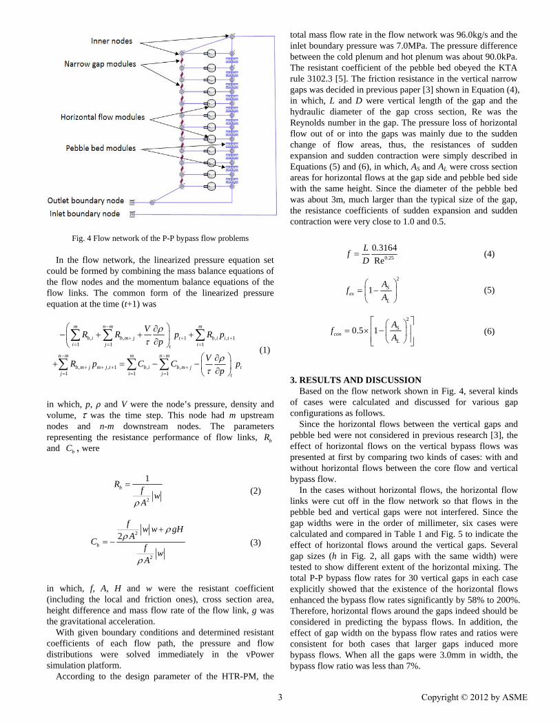
Fig. 4 Flow network of the P-P bypass flow problems In the flow network, the linearized pressure equation set
could be formed by combining the mass balance equations of the flow nodes and the momentum balance equations of the flow links. The common form of the linearized pressure equation at the time (t+1) was
, , 1 , , 11 1 1
m n m m
b i b m j t b i i ti j it
VR R p R p
p
, , 1 , ,1 1 1
n m m n m
b m j m j t b i b m j tj i j t
VR p C C p
p
(1)
in which, p, ρ and V were the node’s pressure, density and volume, was the time step. This node had m upstream nodes and n-m downstream nodes. The parameters representing the resistance performance of flow links, bR and bC , were
2
1bR
fw
A
(2)
2
2
2b
fw w gH
AC
fw
A
(3)
in which, f, A, H and w were the resistant coefficient (including the local and friction ones), cross section area, height difference and mass flow rate of the flow link, g was the gravitational acceleration.
With given boundary conditions and determined resistant coefficients of each flow path, the pressure and flow distributions were solved immediately in the vPower simulation platform.
According to the design parameter of the HTR-PM, the
total mass flow rate in the flow network was 96.0kg/s and the inlet boundary pressure was 7.0MPa. The pressure difference between the cold plenum and hot plenum was about 90.0kPa. The resistant coefficient of the pebble bed obeyed the KTA rule 3102.3 [5]. The friction resistance in the vertical narrow gaps was decided in previous paper [3] shown in Equation (4), in which, L and D were vertical length of the gap and the hydraulic diameter of the gap cross section, Re was the Reynolds number in the gap. The pressure loss of horizontal flow out of or into the gaps was mainly due to the sudden change of flow areas, thus, the resistances of sudden expansion and sudden contraction were simply described in Equations (5) and (6), in which, AS and AL were cross section areas for horizontal flows at the gap side and pebble bed side with the same height. Since the diameter of the pebble bed was about 3m, much larger than the typical size of the gap, the resistance coefficients of sudden expansion and sudden contraction were very close to 1.0 and 0.5.
0 25
0 3164
Re .
L .f
D (4)
2
1 Sex
L
Af
A
(5)
2
0.5 1 Scon
L
Af
A
(6)
3. RESULTS AND DISCUSSION Based on the flow network shown in Fig. 4, several kinds
of cases were calculated and discussed for various gap configurations as follows.
Since the horizontal flows between the vertical gaps and pebble bed were not considered in previous research [3], the effect of horizontal flows on the vertical bypass flows was presented at first by comparing two kinds of cases: with and without horizontal flows between the core flow and vertical bypass flow.
In the cases without horizontal flows, the horizontal flow links were cut off in the flow network so that flows in the pebble bed and vertical gaps were not interfered. Since the gap widths were in the order of millimeter, six cases were calculated and compared in Table 1 and Fig. 5 to indicate the effect of horizontal flows around the vertical gaps. Several gap sizes (h in Fig. 2, all gaps with the same width) were tested to show different extent of the horizontal mixing. The total P-P bypass flow rates for 30 vertical gaps in each case explicitly showed that the existence of the horizontal flows enhanced the bypass flow rates significantly by 58% to 200%. Therefore, horizontal flows around the gaps indeed should be considered in predicting the bypass flows. In addition, the effect of gap width on the bypass flow rates and ratios were consistent for both cases that larger gaps induced more bypass flows. When all the gaps were 3.0mm in width, the bypass flow ratio was less than 7%.
3 Copyright © 2012 by ASME

Table 1 Effect of horizontal flows around gaps on the total bypass
flows for various gap widths
Gap width (mm)
WITHOUT horizontal flows
(kg/s)
WITH horizontal flows
(kg/s)
0.5 0.19 0.56
1.0 0.61 1.35
1.5 1.22 2.30
2.0 1.98 3.48
2.5 2.86 4.75
3.0 3.86 6.12
Fig.5 Effect of horizontal flows on the total bypass flow ratio with various gap widths
Since the irradiation and temperature conditions were quite
different in the reactor core, the gap sizes were not always the same everywhere. In the following case, the 30 gaps in the circumferential of pebble bed were divided into 6 groups, in each group of which, the sizes of 5 vertical gaps were consistent from top to bottom. The gap widths of these 6 groups were 0.5mm, 1.0mm, 1.5mm, 2.0mm, 2.5mm and 3.0mm so that the gap sizes varied in circumferential distributions. Still with horizontal flows in this case, the total P-P bypass flow was 3.13kg/s, 3.26% to the primary flow. To the total bypass flow, the contributions of different gaps were also different due to different gap sizes. In Table 2, the ratios of bypass flows in each group to the total bypass flow were listed. The effect of gap size on the bypass flows was still significant. Larger gaps also resulted in more bypass flows that the 5 gaps with 3.0mm in width occupied about one third of the total bypass flow.
Table 2 Effect of gap sizes on bypass flow in circumferential
distribution
Gap width (mm)
Bypass ratio (%)
0.5 3.0
1.0 7.2
1.5 12.4
2.0 18.6
2.5 25.6
3.0 33.2
Furthermore, different gap size at different height in the
reactor core was considered. A more extreme case was calculated that all the gaps were 3.0mm in width except that the gaps at the core bottom were 5.0mm in width and 1.0m in height. Since the gap sizes were not consistent in the vertical direction from up to down, the pressure distribution, the horizontal flow and the bypass flows might be different from the top to the bottom. The results were compared with the case with all 3.0mm gaps, shown in Table 3. More parameters were compared and listed in Table 3 to explain the effect of gap size variation in the vertical direction. Dp was the pressure difference of the two nodes at two sides of the horizontal flow, one in the pebble bed, the other in the gaps (see Fig. 4). The top Dp and bottom Dp were pressure differences of the pair nodes at the top and bottom of the flow network of reactor core, in which, negative value meant the directions of the horizontal flows was from the gaps to the pebble bed, while positive value meant flow from the pebble to the gaps. The top bypass flow was flow from the cold plenum to the gaps, while the bottom bypass flow was flow from the gaps to the hot plenum.
According to the flow network in Fig. 4, the pebble bed and vertical gaps shared the same nodes at the top (cold plenum) and bottom (hot plenum). The resistance of the pebble bed and narrow gaps induced the pressure distributions in the reactor and decided that horizontal flows were from gaps to the pebble bed at the top and reversed at the bottom. For all the aforementioned cases with the consistent gap sizes in the vertical direction, the top Dp and bottom Dp were almost the same (45.0Pa) so that the top and bottom bypass ratio were very close (see the values in the “All 3.0mm” case in Table 3). When the 1.0m-high bottom gaps increased from 3.0mm to 5.0mm, the pressure difference and bypass at the top were not changed, but the bottom were obviously affected. The bottom Dp became more than twice larger in enhancing the horizontal flows from the pebble bed to the gaps so that the bottom bypass flow ratio increased from 6.2% to 11.1%. Therefore, the vertical distribution of the gap size was also important for bypass flow predictions.
4 Copyright © 2012 by ASME

Table 3 Effect of larger gap sizes on bypass flows at the bottom of reactor core
Cases Top Dp
(Pa)
Top bypass ratio (%)
Bottom Dp (Pa)
Bottom bypass ratio
(%)
All 3.0mm -45.0 6.4 45.0 6.2
Bottom 5.0mm -45.0 6.4 102.0 11.1
4. CONCLUSIONS
The flow network was built considering the main flow in the pebble bed and bypass flows in many vertical gaps between graphite side reflectors in the HTR-PM reactor core. The horizontal flows around those vertical gaps had strong effect on the bypass flows so that they must be established in the flow network of predicting bypass flows. Not only the gap sizes but also the gap size distributions in the reactor core were important to the bypass flows. Larger gaps induced more pressure difference and more horizontal flows between the pebble bed and vertical gaps so that the bypass flow ratios were larger.
In our future work, the P-P bypass flow paths and the horizontal flow paths will be modeled using computational fluid dynamic tools according to more realistic shapes and configurations with thermal expansion and irradiation deformation. More reasonable distributions of the gap widths will be analyzed. And more accurate bypass flow ratios will then be calculated in more complete flow network.
ACKNOWLEDGEMENT This work has been supported by the National S&T Major Project (Grant No. ZX06901). The flow network was modeled and solved on the vPower simulation platform developed by Beijing Neoswise Technology Co. Ltd. REFERENCES [1] Zhang, Z., Wu, Z., et al., 2009, Current status and
technical description of Chinese 2×250 MWth HTR-PM demonstration plant, Nucl. Eng. Des., Vol. 239, pp. 1212-1219.
[2] Gao, Z., and Shi, L., 2002, Thermal hydraulic calculation of the HTR-10 for the initial and equilibrium core, Nucl. Eng. Des., Vol. 218, pp. 51–64.
[3] Sun, J., Zheng, Y., Li F., et al., 2011, Prediction of bypass flows in HTR-PM by the flow network method, 19th International Conference on Nuclear Engineering, Osaka, Japan.
[4] Sui Z., Cui B. and Ma Y., 2011, The Dynamic Mathematic Simulation Model of Steam Generator for HTR-PM, 19th International Conference on Nuclear Engineering, Osaka, Japan.
[5] KTA 3102.3, 1981, Reactor core design of high-temperature gas-cooled reactors part 3: loss of pressure through friction in pebble bed cores, Nuclear Safety Standards Commission (KTA),Federal Republic of Germany.
5 Copyright © 2012 by ASME