
research report - STEEL FRAMING · research report Cold-Formed Steel Gable ... A Research Project...
108
research report Cold-Formed Steel Gable End Wall Design Using the Prescriptive Method for One and Two Family Dwellings RESEARCH REPORT RP05-2 2005 REVISION 2006 American Iron and Steel Institute
Transcript of research report - STEEL FRAMING · research report Cold-Formed Steel Gable ... A Research Project...
rese
arch
repo
rt
Cold-Formed Steel Gable End Wall Design Using the Prescriptive Method for One and Two Family Dwellings
R E S E A R C H R E P O R T R P 0 5 - 2 2 0 0 5 R E V I S I O N 2 0 0 6
American Iron and Steel Institute
Cold-Formed Steel Gable End Wall Design Using the Prescriptive Method i
DISCLAIMER
The material contained herein has been developed by researchers based on their research findings and is for general information only. The information in it should not be used without first securing competent advice with respect to its suitability for any given application. The publication of the information is not intended as a representation or warranty on the part of the American Iron and Steel Institute, Steel Framing Alliance, or of any other person named herein, that the information is suitable for any general or particular use or of freedom from infringement of any patent or patents. Anyone making use of the information assumes all liability arising from such use.
Copyright 2005 American Iron and Steel Institute / Steel Framing Alliance
Revised Edition Copyright 2006 American Iron and Steel Institute / Steel Framing Alliance
ii Cold-Formed Steel Gable End Wall Design Using the Prescriptive Method
PREFACE
This report was developed by the University of Missouri-Rolla for the Steel Framing Alliance and the Prescriptive Methods Subcommittee of the AISI Committee on Framing Standards. The primary objective of this project was to create the documentation necessary to enable the expansion of the AISI Standard for Cold-Formed Steel Framing – Prescriptive Method for One and Two Family Dwellings for gable end walls.
Research Team Steel Framing Alliance
Civil Engineering Study 05-1 Cold-Formed Steel Series
Final Report
COLD-FORMED STEEL GABLE END WALL DESIGN USING THE
PRESCRIPTIVE METHOD FOR ONE AND TWO FAMILY DWELLINGS
by
Benjamin W. Downey Research Assistant
Sutton F. Stephens Roger A. LaBoube Project Directors
A Research Project Sponsored by the Steel Framing Alliance
March, 2005
Department of Civil Engineering Wei-Wen Yu Center for Cold-Formed Steel Structures
University of Missouri-Rolla Rolla, Missouri
PREFACE
Cold-formed steel is gradually gaining acceptance in the residential
construction sector. This is due in large part to the development of specifications and
guidelines which aid in the design process. One such publication, the Prescriptive
Method, is particularly attractive for residential projects, since it allows standard one and
two story buildings to be designed without the aid of a design professional. One
significant omission in the current Prescriptive Method is the design of gable end wall
studs. As requested by the AISI Committee on Framing Standards (COFS), this report
presents the tables and details necessary to incorporate gable end wall design into
future editions of the Prescriptive Method. This report also serves as a commentary on
these design aids, explaining the design methodologies and assumptions used in their
creation. This study and report was limited to developing the necessary information to
incorporate gable end walls in the Prescriptive Method and does not address design
issues not presently incorporated in the Prescriptive Method. Also, where a design
solution currently exists in the Prescriptive Method such design solution is not repeated
herein.
Three primary gable end construction methods are explored: balloon framing,
gable end truss framing, and cathedral ceiling framing. To resist wind forces, the balloon
and gable end wall methods are provided with an out-of-plane bracing option using
horizontal ceiling diaphragms. Additional design considerations including bottom track
attachment to floors or foundations and requirements for openings in gable end walls are
also addressed. Example calculations are included to support each of the design aids
presented.
i
This report is based on a thesis submitted to the Faculty of the Graduate School
of the Kansas State University in partial fulfillment of the requirements for the degree of
Masters of Science in Architectural Engineering.
Technical guidance for this study was provided by the Steel Framing Alliance’s
Project Monitoring Task Group (W. Babich, S.R. Fox, K. Pagano, S.H. Walker), and the
American Iron and Steel Institute’s Prescriptive Method Subcommittee (S.R. Fox,
Chairperson). The Project Monitoring Task Group and the Subcommittee’s guidance is
gratefully acknowledged. Thanks are also extended to J.W. Larson, AISI staff for his
guidance and assistance.
ii
1.0 Loads
1.1 Load Types
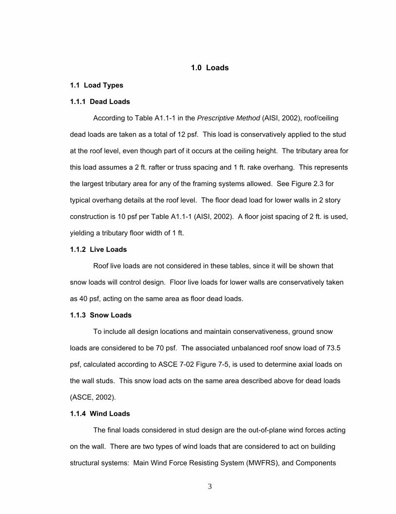
1.1.1 Dead Loads
According to Table A1.1-1 in the Prescriptive Method (AISI, 2002), roof/ceiling
dead loads are taken as a total of 12 psf. This load is conservatively applied to the stud
at the roof level, even though part of it occurs at the ceiling height. The tributary area for
this load assumes a 2 ft. rafter or truss spacing and 1 ft. rake overhang. This represents
the largest tributary area for any of the framing systems allowed. See Figure 2.3 for
typical overhang details at the roof level. The floor dead load for lower walls in 2 story
construction is 10 psf per Table A1.1-1 (AISI, 2002). A floor joist spacing of 2 ft. is used,
yielding a tributary floor width of 1 ft.
1.1.2 Live Loads
Roof live loads are not considered in these tables, since it will be shown that
snow loads will control design. Floor live loads for lower walls are conservatively taken
as 40 psf, acting on the same area as floor dead loads.
1.1.3 Snow Loads
To include all design locations and maintain conservativeness, ground snow
loads are considered to be 70 psf. The associated unbalanced roof snow load of 73.5
psf, calculated according to ASCE 7-02 Figure 7-5, is used to determine axial loads on
the wall studs. This snow load acts on the same area described above for dead loads
(ASCE, 2002).
1.1.4 Wind Loads
The final loads considered in stud design are the out-of-plane wind forces acting
on the wall. There are two types of wind loads that are considered to act on building
structural systems: Main Wind Force Resisting System (MWFRS), and Components
3
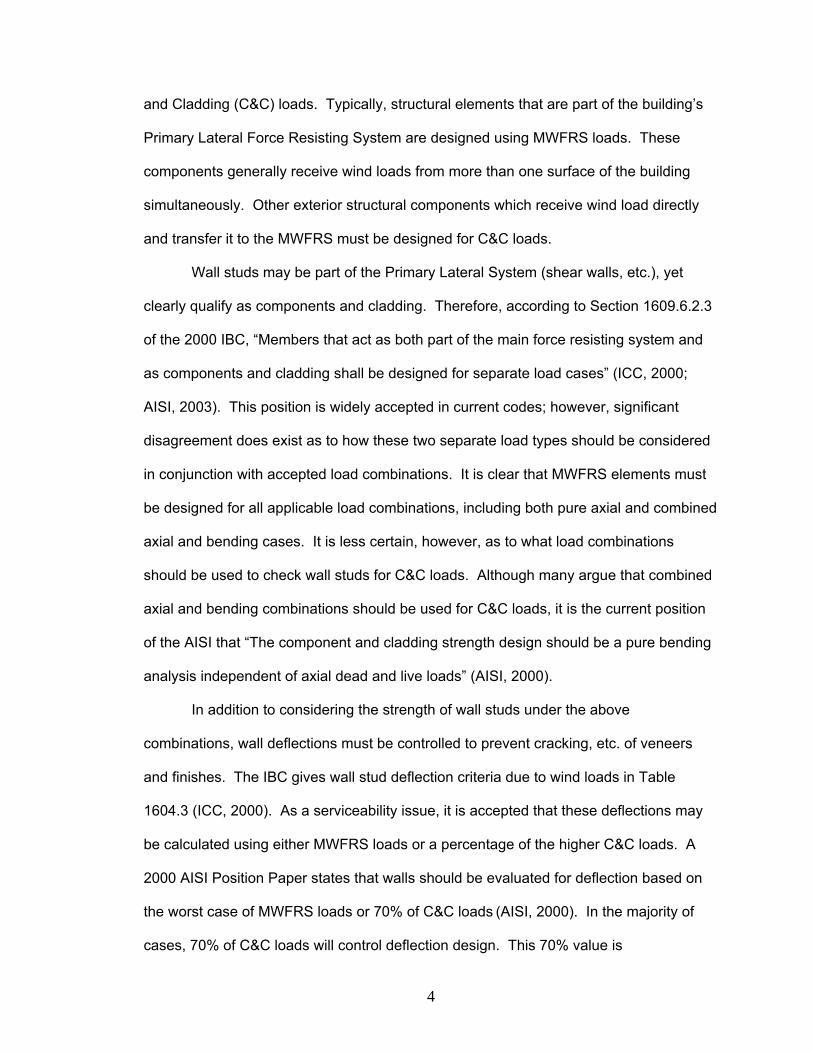
and Cladding (C&C) loads. Typically, structural elements that are part of the building’s
Primary Lateral Force Resisting System are designed using MWFRS loads. These
components generally receive wind loads from more than one surface of the building
simultaneously. Other exterior structural components which receive wind load directly
and transfer it to the MWFRS must be designed for C&C loads.
Wall studs may be part of the Primary Lateral System (shear walls, etc.), yet
clearly qualify as components and cladding. Therefore, according to Section 1609.6.2.3
of the 2000 IBC, “Members that act as both part of the main force resisting system and
as components and cladding shall be designed for separate load cases” (ICC, 2000;
AISI, 2003). This position is widely accepted in current codes; however, significant
disagreement does exist as to how these two separate load types should be considered
in conjunction with accepted load combinations. It is clear that MWFRS elements must
be designed for all applicable load combinations, including both pure axial and combined
axial and bending cases. It is less certain, however, as to what load combinations
should be used to check wall studs for C&C loads. Although many argue that combined
axial and bending combinations should be used for C&C loads, it is the current position
of the AISI that “The component and cladding strength design should be a pure bending
analysis independent of axial dead and live loads” (AISI, 2000).
In addition to considering the strength of wall studs under the above
combinations, wall deflections must be controlled to prevent cracking, etc. of veneers
and finishes. The IBC gives wall stud deflection criteria due to wind loads in Table
1604.3 (ICC, 2000). As a serviceability issue, it is accepted that these deflections may
be calculated using either MWFRS loads or a percentage of the higher C&C loads. A
2000 AISI Position Paper states that walls should be evaluated for deflection based on
the worst case of MWFRS loads or 70% of C&C loads (AISI, 2000). In the majority of
cases, 70% of C&C loads will control deflection design. This 70% value is
4
conservatively based on the following statement found in the commentary to Appendix B
of ASCE 7-98: “Use of factored wind load in checking serviceability is exclusively
conservative. The load combination with an annual probability of 0.05 of being
exceeded, which can be used in checking short-term effects, is D + 0.5L + 0.7W”
(ASCE, 1998).
To comply with these requirements, walls in the Prescriptive Method are
designed for all applicable load combinations using MWFRS wind loads, and a pure
bending combination using C&C loads. Deflections are checked using 70% of C&C
loads against an h/240 deflection criteria, consistent with brittle veneers (ICC, 2000;
AISI, 2003). All wind loads for studs in the Prescriptive Method are taken in the middle
of the wall, away from the higher loads found at the corners. The Prescriptive Method
does this because it assumes that the use of these higher wind loads for design of the
entire wall would result in an overly conservative and uneconomical wall design (AISI,
2003).
1.2 Load Combination
The following load combinations from IBC 2000 must be considered in gable end
wall design (ICC, 2000):
1.4D Formula 16-1 1.2D + 1.6L + 0.5(Lr or S or R) Formula 16-2 1.2D + 1.6(Lr or S or R) + (f1L or 0.8W) Formula 16-3 1.2D + 1.6W + f1L + 0.5(Lr or S or R) Formula 16-4 1.2D + 1.0E + f1L + f2S Formula 16-5 0.9D + (1.0E or 1.6W) Formula 16-6
Where: D = Roof/Ceiling or Floor Dead Load L = Live Load Lr = Roof Live Load S = Snow Load R = Rain Load W = Wind Load E = Seismic Load
5
For gable end wall design, Formula 16-1 has been ignored due to the small
amount of dead load on the studs. In Formulas 16-2 and 16-4, snow loads are assumed
to control over roof live loads and rain loads. Formula 16-5 is neglected, since seismic
effects rarely control out of plane wall design in the Prescriptive Method. Per IBC
Section 1605, f1 is taken as 0.5 in applicable combinations to coincide with typical live
load conditions (ICC, 2000). With these assumptions, the combinations are adapted to
gable end wall design as follows:
(1) 1.2D + 1.6L + 0.5S (2) 1.2D + 0.5L + 1.6S (3) 1.2D + 0.8W + 1.6S (4) 1.2D + 1.6W + 0.5L + 0.5S (5) 0.9D + 1.6W (6) 1.6W (7) 0.7W
For the pure axial load combinations (1) and (2), dead, live, and snow loads are
applied as described above. In the combined axial and bending combinations (3) and
(4), the wind load considered is the MWFRS load. Load combination (5) is considered
for uplift design of roof overhangs, and stud to top track connections using C&C loads. It
is also considered for combined shear and uplift for the bottom track connections to
supporting structure using MWFRS loads. C&C loads are also used in the pure bending
combination (6), which has been added to comply with current AISI requirements as
previously discussed (AISI, 2000). Finally, load combination (7) is used to check mid-
height wall deflections using C&C loads. In all of these combinations, design checks are
made on the tallest stud at the middle of the gable end wall. Web crippling was also
checked for the controlling load combination.
For full-height walls that carry only roof/ceiling axial loads, only load
combinations (3), (4), (6), and (7) are considered, since it is assumed that the pure axial
cases (1) and (2) will not control over the combined axial/bending combinations (3) and
(4). For lower walls in 2-story structures, all combinations except (5) are used.
6
2.0 Wall Framing Methods
2.1 Balloon Gable Framing
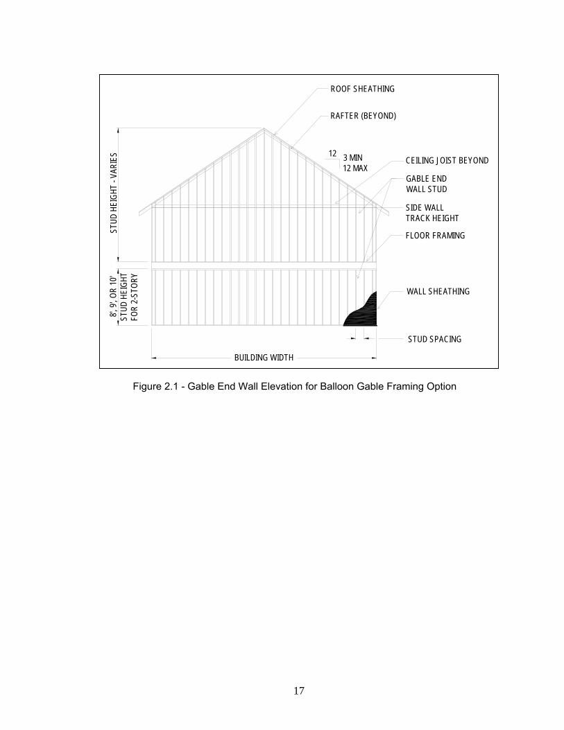
Construction of full height balloon-framed stud walls is an efficient and
economical method for framing gable end walls of residential structures. A typical
elevation of this construction technique is shown in Figure 2.1. These stud walls resist
both out-of-plane wind forces and axial roof loads. Two construction options were
considered for this design:
1. Unbraced Full Height Wall 2. Wall Braced by Horizontal Ceiling Diaphragm.
The tables and details for these design options are presented below, along with
pertinent design assumptions.
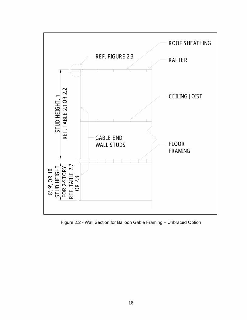
2.1.1 Unbraced Option
For many low-slope roofs and/or narrow buildings, it is possible to construct the
gable end as a full height balloon framed wall without intermediate out-of-plane support
for strong axis bending. This method is illustrated in Figure 2.2.
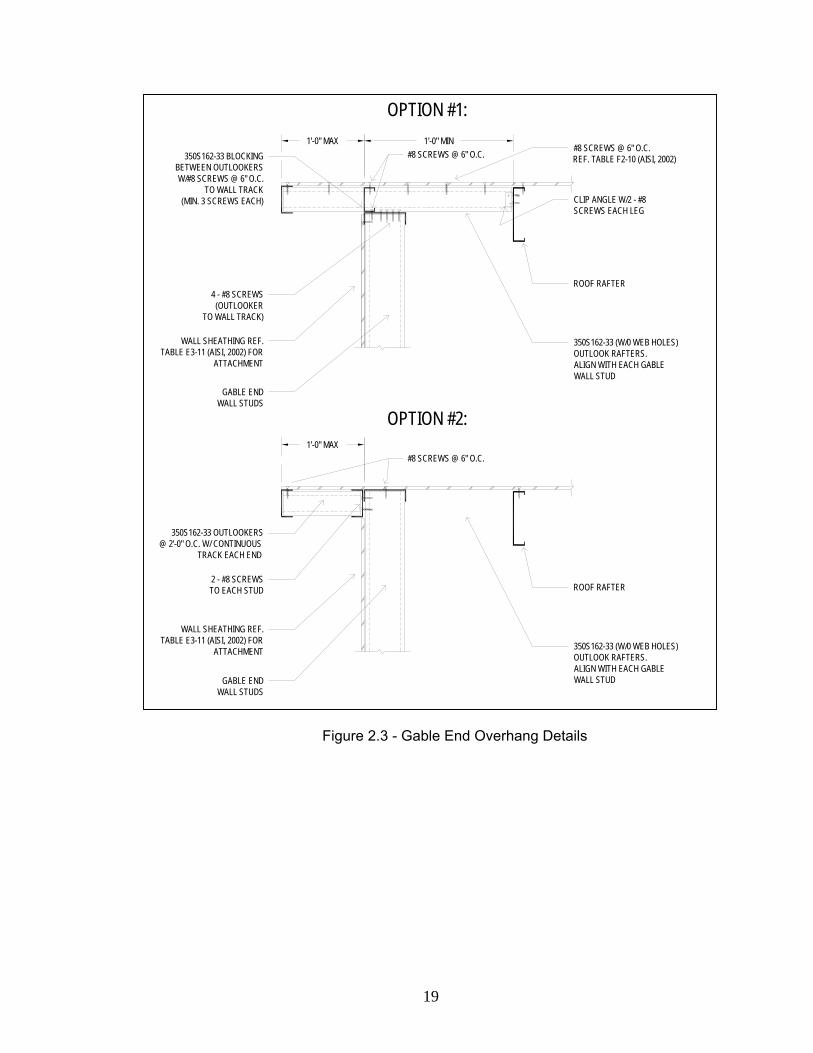
Typical construction details for the gable end overhang along the rake are shown
in Figure 2.3. Figure 2.8 (Prescriptive Method Figure D2.4) shows typical blocking
configurations and connections for overhangs according to the Prescriptive Method.
Appendix A includes a calculation for the number of screws required in these
connections. These screws must resist shear forces, uplift (tension) forces, and the
combined effect of shear and tension.
The appropriate full height stud thickness for a given wall height, h (ft.), and wind
speed can be selected from Table 2.1 or Table 2.2. These tables consider the following
design checks: combined axial load and bending, pure strong axis bending, member
deflection, and web crippling. The controlling check is determined from among these
and used to establish the stud selections shown.
7
For combined axial load and bending, load combinations (3) and (4) are checked.
Factored axial loads are applied at the roof level, and lateral stud bracing is assumed at
48 in. on center spacing. For the pure strong axis bending check of load combination
(6), the stud is modeled as a full height simply supported beam between the structural
tracks, with length h. Deflection is checked against a maximum mid-height deflection of
h/240. The resulting stud thicknesses listed in the table are based on calculations for
the wind load acting on an area equal to the height, h, times the stud spacing. Finally,
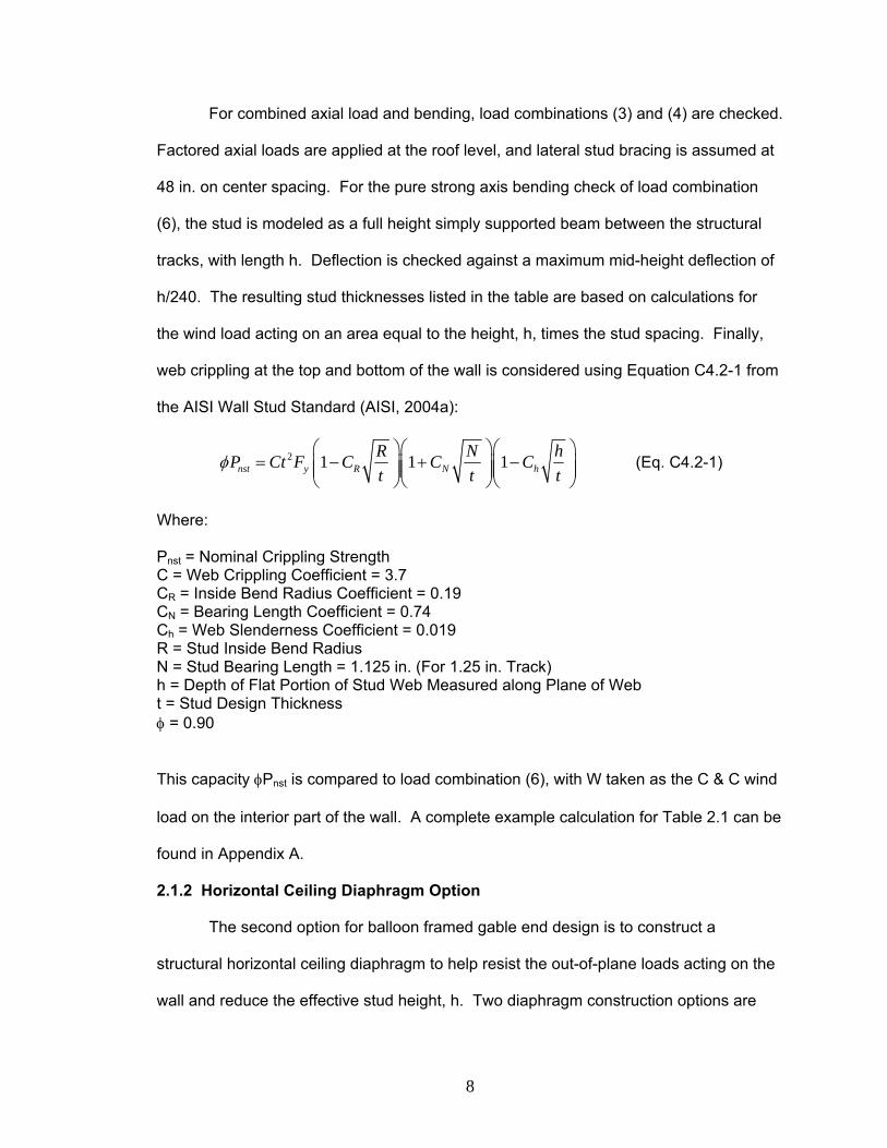
web crippling at the top and bottom of the wall is considered using Equation C4.2-1 from
the AISI Wall Stud Standard (AISI, 2004a):
2 1 1 1nst y R N hR N hP Ct F C C Ct t
φ⎛ ⎞⎛ ⎞⎛
= − + −⎜ ⎟⎜ ⎟⎜⎜ ⎟⎜ ⎟⎜⎝ ⎠⎝ ⎠⎝ t
⎞⎟⎟⎠
(Eq. C4.2-1)
Where:
Pnst = Nominal Crippling Strength C = Web Crippling Coefficient = 3.7 CR = Inside Bend Radius Coefficient = 0.19 CN = Bearing Length Coefficient = 0.74 Ch = Web Slenderness Coefficient = 0.019 R = Stud Inside Bend Radius N = Stud Bearing Length = 1.125 in. (For 1.25 in. Track) h = Depth of Flat Portion of Stud Web Measured along Plane of Web t = Stud Design Thickness φ = 0.90
This capacity φPnst is compared to load combination (6), with W taken as the C & C wind
load on the interior part of the wall. A complete example calculation for Table 2.1 can be
found in Appendix A.
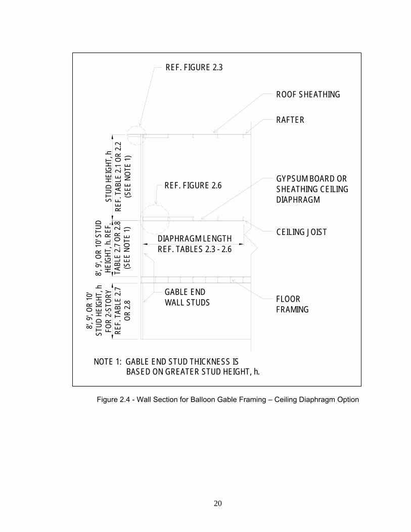
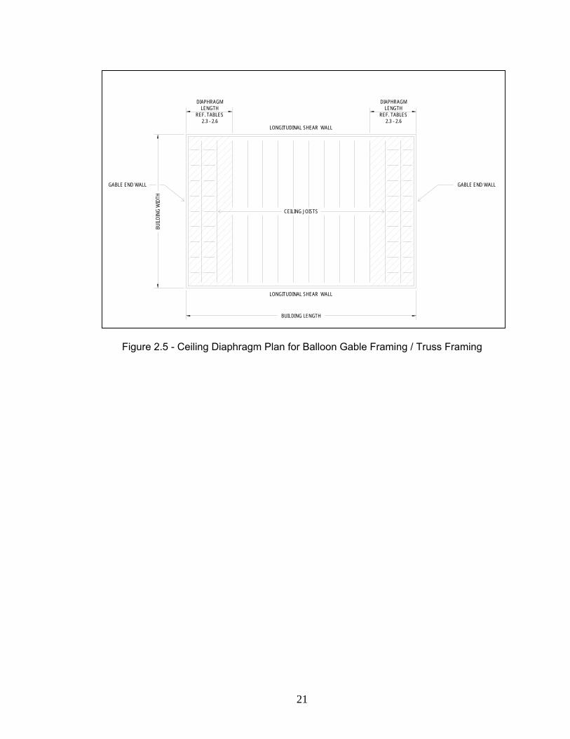
2.1.2 Horizontal Ceiling Diaphragm Option
The second option for balloon framed gable end design is to construct a
structural horizontal ceiling diaphragm to help resist the out-of-plane loads acting on the
wall and reduce the effective stud height, h. Two diaphragm construction options are
8
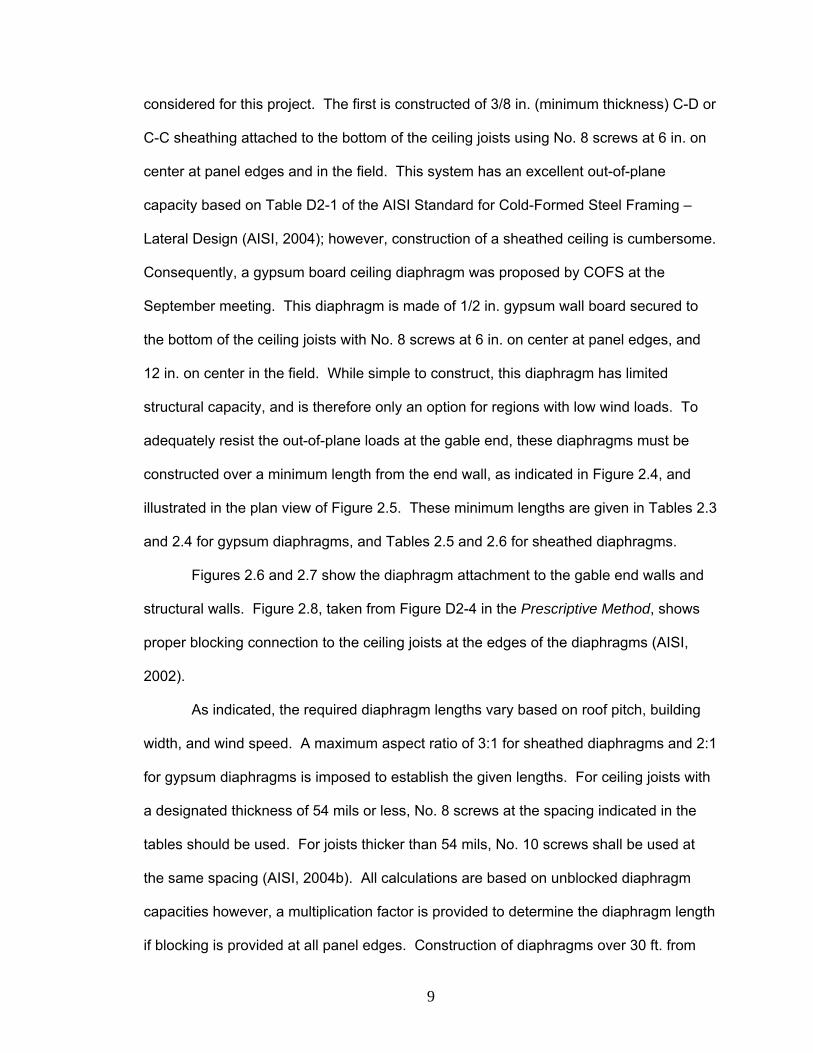
considered for this project. The first is constructed of 3/8 in. (minimum thickness) C-D or
C-C sheathing attached to the bottom of the ceiling joists using No. 8 screws at 6 in. on
center at panel edges and in the field. This system has an excellent out-of-plane
capacity based on Table D2-1 of the AISI Standard for Cold-Formed Steel Framing –
Lateral Design (AISI, 2004); however, construction of a sheathed ceiling is cumbersome.
Consequently, a gypsum board ceiling diaphragm was proposed by COFS at the
September meeting. This diaphragm is made of 1/2 in. gypsum wall board secured to
the bottom of the ceiling joists with No. 8 screws at 6 in. on center at panel edges, and
12 in. on center in the field. While simple to construct, this diaphragm has limited
structural capacity, and is therefore only an option for regions with low wind loads. To
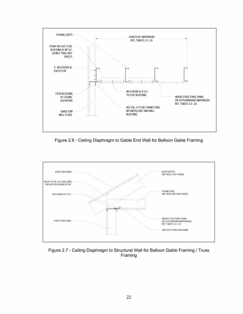
adequately resist the out-of-plane loads at the gable end, these diaphragms must be
constructed over a minimum length from the end wall, as indicated in Figure 2.4, and
illustrated in the plan view of Figure 2.5. These minimum lengths are given in Tables 2.3
and 2.4 for gypsum diaphragms, and Tables 2.5 and 2.6 for sheathed diaphragms.
Figures 2.6 and 2.7 show the diaphragm attachment to the gable end walls and
structural walls. Figure 2.8, taken from Figure D2-4 in the Prescriptive Method, shows
proper blocking connection to the ceiling joists at the edges of the diaphragms (AISI,
2002).
As indicated, the required diaphragm lengths vary based on roof pitch, building
width, and wind speed. A maximum aspect ratio of 3:1 for sheathed diaphragms and 2:1
for gypsum diaphragms is imposed to establish the given lengths. For ceiling joists with
a designated thickness of 54 mils or less, No. 8 screws at the spacing indicated in the
tables should be used. For joists thicker than 54 mils, No. 10 screws shall be used at
the same spacing (AISI, 2004b). All calculations are based on unblocked diaphragm
capacities however, a multiplication factor is provided to determine the diaphragm length
if blocking is provided at all panel edges. Construction of diaphragms over 30 ft. from
9
each end wall would exceed the maximum overall building length of 60 ft. give in Table
A1.1-1 in the Prescriptive Method; therefore, diaphragm lengths over 30 ft. have only
been included in Tables 2.3 and 2.4 for use in diaphragm calculations for reduced
fastener spacing and blocking options. Refer to Appendix A for typical diaphragm length
calculations for both construction options.
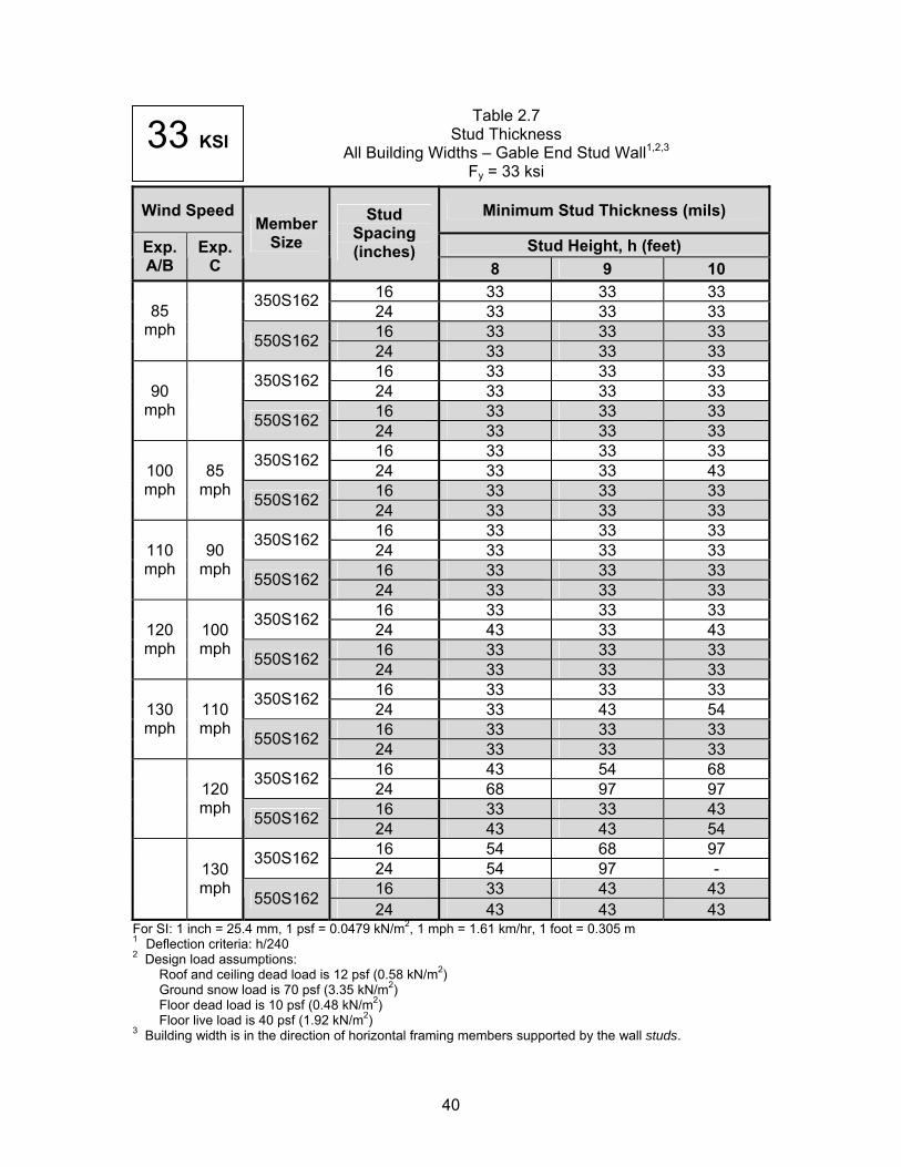
Table 2.7 considers all of the same design checks as Tables 2.1 and 2.2
including combined axial and bending, pure bending, deflection (h/240 criteria), and web
crippling. Table 2.7 may be also be used for stud walls on lower floors of 2-story
construction, as shown in Figure 2.9. Studs in these walls resist greater axial forces
than those under the gable end wall assembly. Therefore, stud sections in Table 2.7 are
also checked for the pure axial combinations (1) and (2), in addition to the checks above.
The factored axial load resisted by these sections is calculated using a floor dead load of
10 psf, and a floor live load of 40 psf, as described previously.
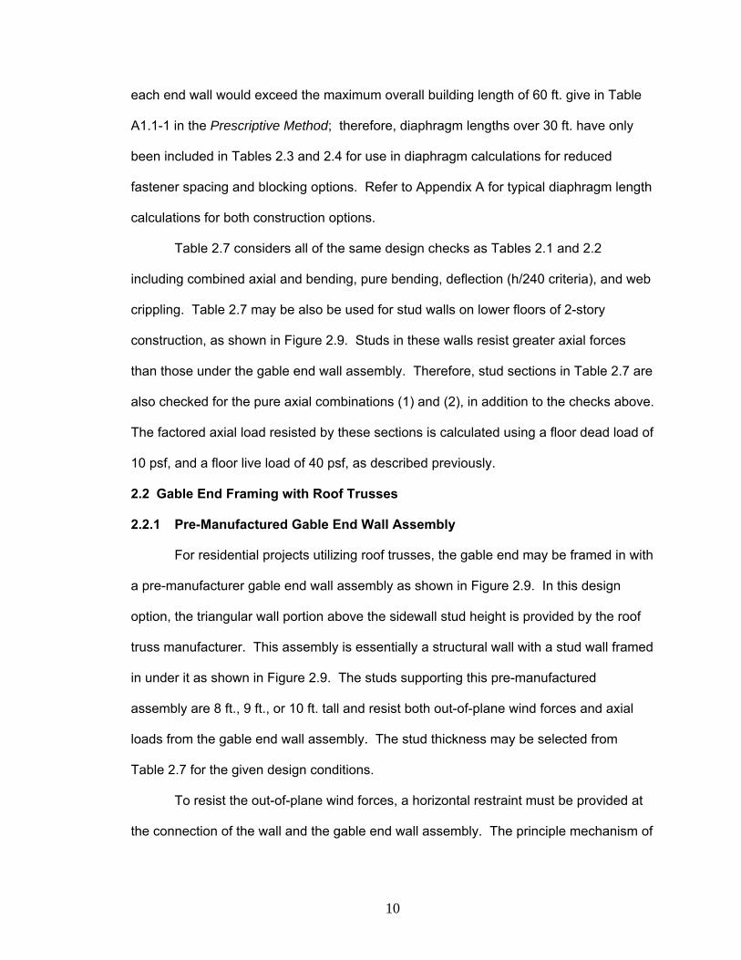
2.2 Gable End Framing with Roof Trusses
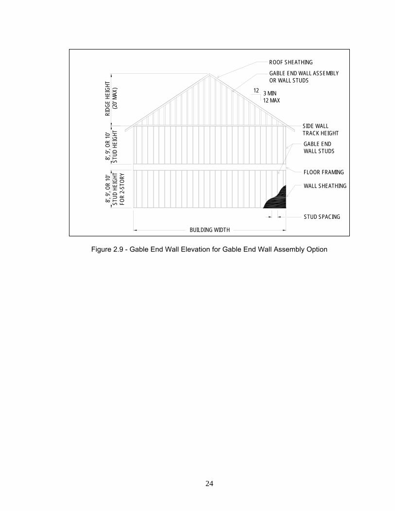
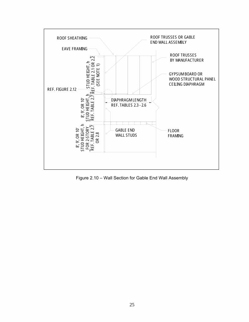
2.2.1 Pre-Manufactured Gable End Wall Assembly
For residential projects utilizing roof trusses, the gable end may be framed in with
a pre-manufacturer gable end wall assembly as shown in Figure 2.9. In this design
option, the triangular wall portion above the sidewall stud height is provided by the roof
truss manufacturer. This assembly is essentially a structural wall with a stud wall framed
in under it as shown in Figure 2.9. The studs supporting this pre-manufactured
assembly are 8 ft., 9 ft., or 10 ft. tall and resist both out-of-plane wind forces and axial
loads from the gable end wall assembly. The stud thickness may be selected from
Table 2.7 for the given design conditions.
To resist the out-of-plane wind forces, a horizontal restraint must be provided at
the connection of the wall and the gable end wall assembly. The principle mechanism of
10
providing this restraint is to utilize a horizontal structural diaphragm at ceiling level as
shown in Figure 2.10.
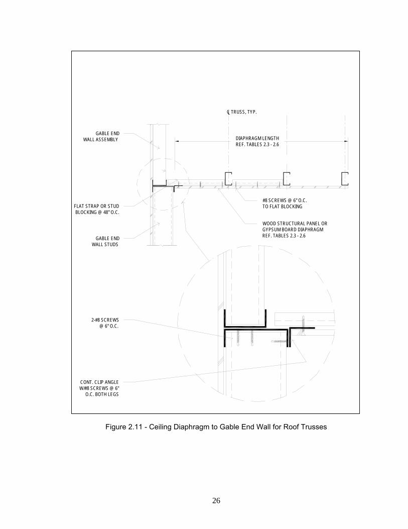
Similar to balloon gable framing, this diaphragm may be composed of either
gypsum board or wood structural panels, and must be constructed over the minimum
lengths given in Tables 2.3 – 2.6, as illustrated in Figure 2.5. Refer to Figure 2.7 for
attachment at the longitudinal shear walls. The connection at the gable end wall is
detailed in Figure 2.11. Refer to the balloon framing option in section 2.1 for a
discussion of the design methodology and assumptions used to develop the minimum
diaphragm lengths in Tables 2.3 – 2.6.
2.2.2 Gable Infill Stud Wall
This option is an alternative to using the pre-manufactured gable end assembly
as described in Section 2.2.1 (Figure 2.10). Rather than utilizing a triangular gable end
assembly that is provided by the truss manufacturer, the wall can be built as a stud wall,
selecting the thickness of studs from Table 2.1. Like the pre-manufactured gable end
wall assembly, this wall system must be braced horizontally at the ceiling line where the
two walls are attached as shown in Figure 2.11. The lower wall supporting the triangular
shaped portion of the gable end wall will be selected as described in Section 2.2.1.
2.2.3 Full Height Balloon Gable Framing
Another option for framing the gable end wall is to use balloon gable framing
similar to that described in Section 2.1.1. The wall studs are full height studs without
bracing at the ceiling. Studs for this option are selected from Table 2.1 and overhangs
are constructed according to Figure 2.3.
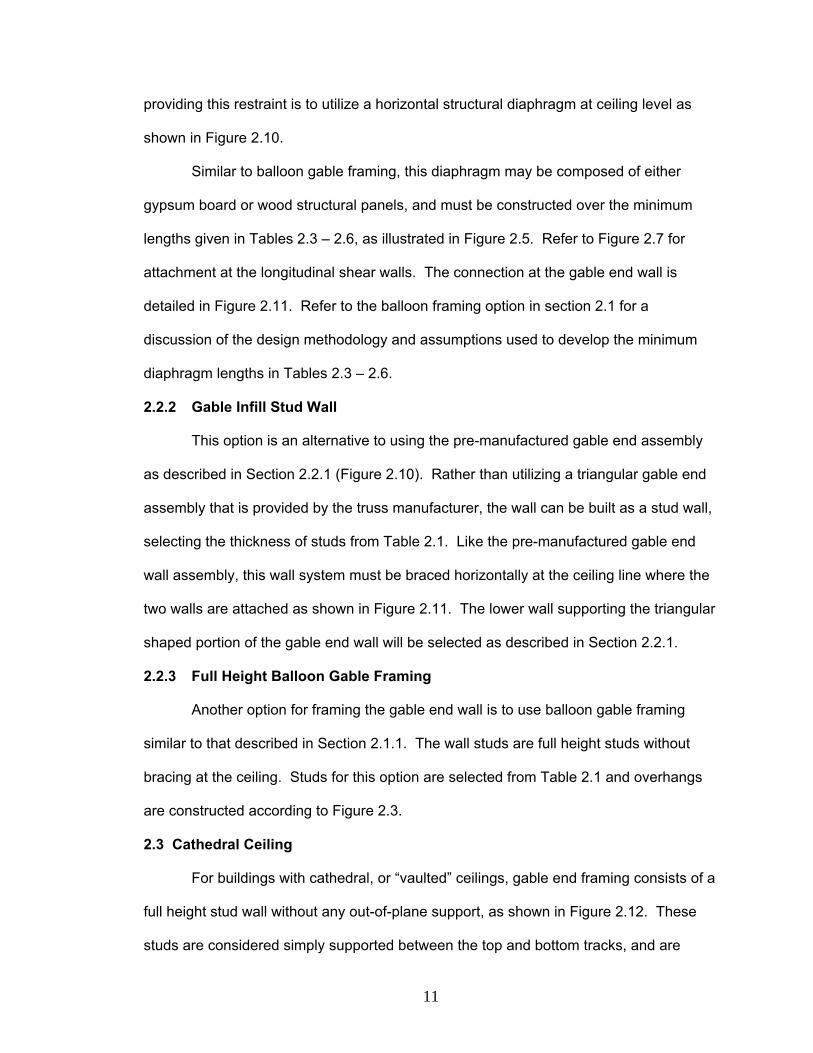
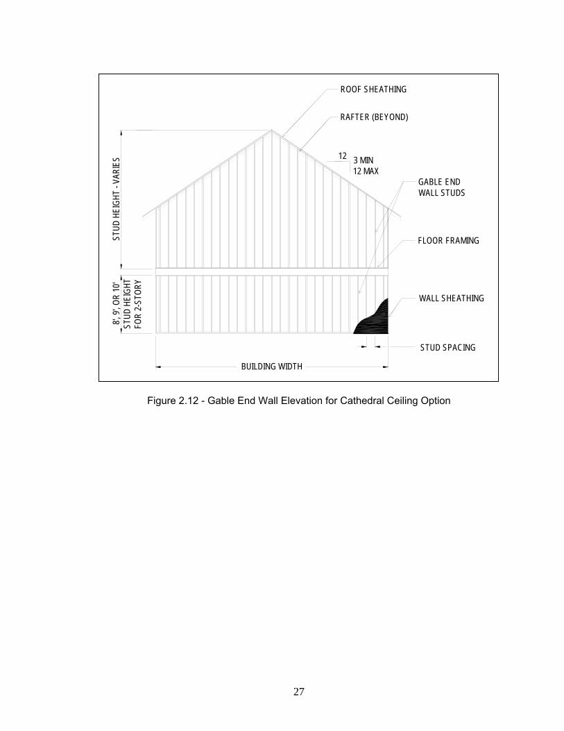
2.3 Cathedral Ceiling
For buildings with cathedral, or “vaulted” ceilings, gable end framing consists of a
full height stud wall without any out-of-plane support, as shown in Figure 2.12. These
studs are considered simply supported between the top and bottom tracks, and are
11
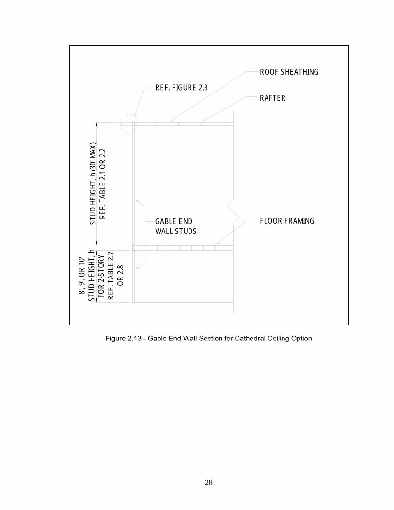
designed as previously discussed. A typical section of this construction is shown in
Figure 2.13. Figure 2.3 details proper overhang design at the top of the wall.
The proper stud size and thickness for a given stud height, h, can be selected
from Tables 2.1 or 2.2. To comply with the building width and roof slope limitations set
forth in Table A1.1-1 in the Prescriptive Method, these studs may have heights up to 30
ft. at the center of the wall. However, it is clear from Tables 2.1 and 2.2 that construction
of walls over 20 ft. tall is not possible with 3.5 in. or 5.5 in. studs.
12
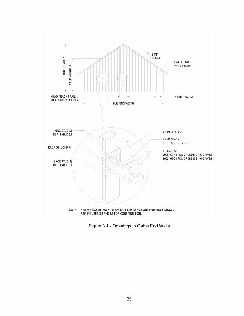
3.0 Openings in Gable End Walls
3.1 General
Many residential structures have openings for windows and/or doors in the gable
end walls. Care must be given to ensure that members around openings are designed
for the redistributed axial and wind forces. This involves design of both the king and jack
studs on either side of the opening, and of the header tracks at the top (and bottom for
windows) of the opening. A typical opening detail is shown in Figure 3.1.
3.2 Studs Around Openings
King and jack studs are used on both sides of wall openings to resist the loads
transferred around the opening. In gable end walls, these loads include both axial dead
and snow loads from the roof, and out-of-plane wind loads. These wind loads consist of
both uniform loads from the exposed wall surface, and a point load at the header track
location. King studs run the full height of the wall. Jack studs, on the other hand,
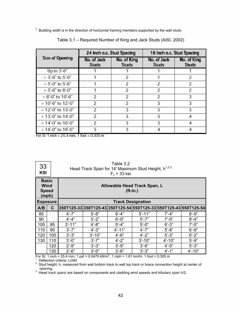
provide support the header as shown in Figure 3.1. Per Table 3.1 (Table E7-24 in the
current Prescriptive Method), the total number of king studs required on each side of the
opening is equal to the number of studs eliminated in the opening divided by two (AISI,
2002), rounded up to the nearest stud. The number of jack studs depends on the
opening width, as shown in Table 3.1. These studs should be the same thickness as the
wall studs. For example, if an opening interrupts three wall studs, two king studs and
one jack stud should be placed on each side of the opening to compensate.
3.3 Headers
Due to the limited axial load on gable end walls, use of the bearing wall header
tables in the current Prescriptive Method results in overly conservative designs.
Consequently, 2-600S162-43 sections shall be used for less than 6 ft. wide in gable end
walls. Openings over 6 ft. require 2-800S162-54 sections. These sections may be
arranged in either back to back or box configurations, as shown in Figure 3.1
13
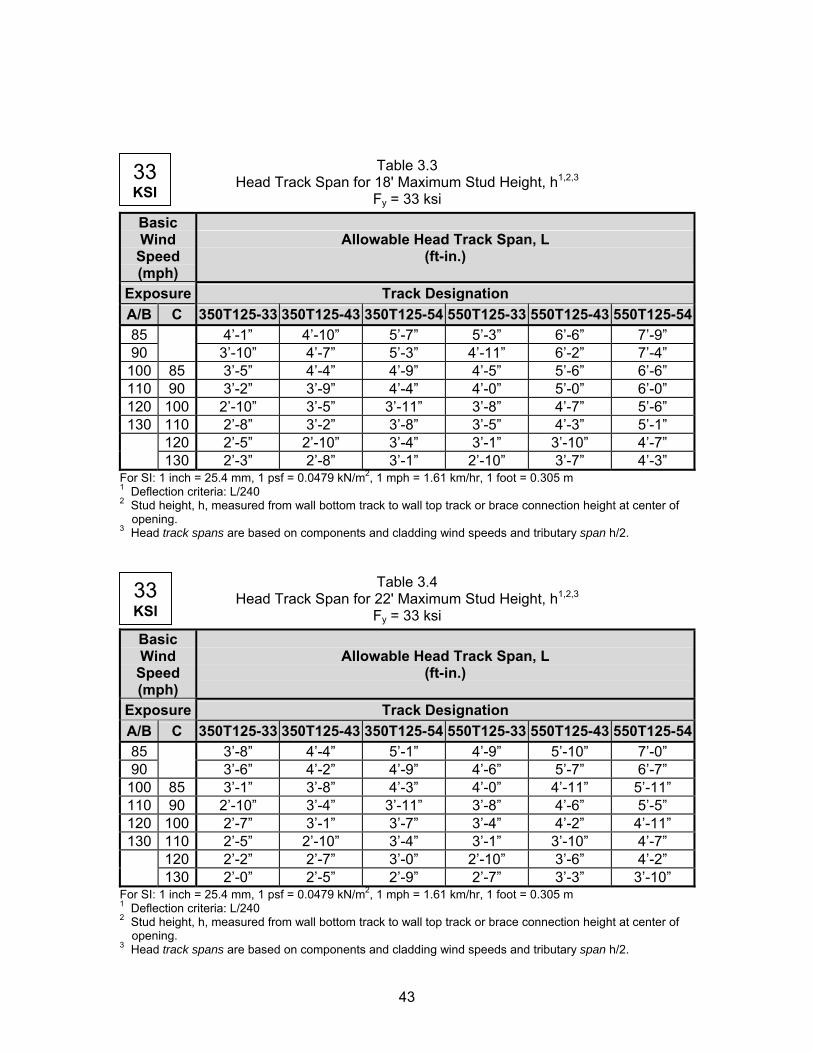
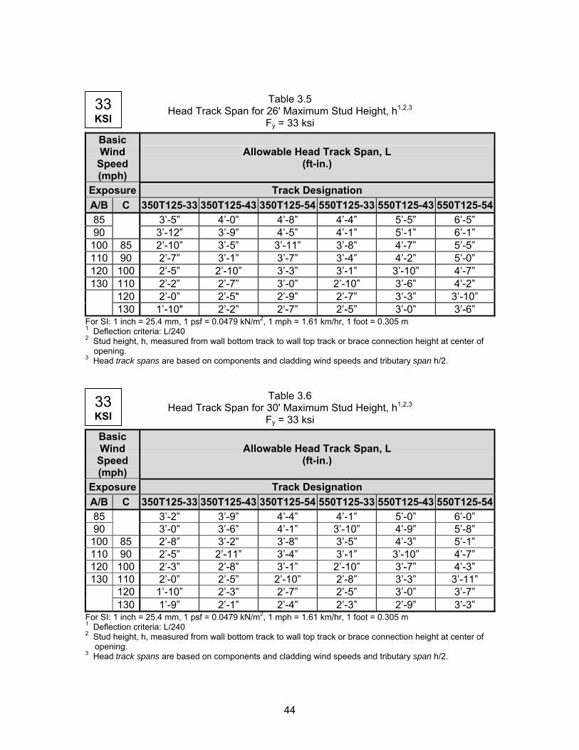
Though the axial loads on gable end walls are minimal, the out-of-plane loads
due to wind are quite significant. Consequently, the head tracks over the opening must
be designed to resist these forces. The track is designed to resist a tributary width equal
to h/2, where h is the height of the wall at the center of the opening. Tables 3.2 - 3.6
give the maximum allowable head track spans, L, for various track sections, wind
speeds, and building heights. Stud heights shall be rounded up to the nearest given
height to determine the appropriate track spans. These spans are based on an
unbraced length of 24 in., corresponding with a stud spacing of 24 in. on center. To
maintain consistency with the current head track span table in the Prescriptive Method
(Table E7-25), only 33 ksi material and 33, 43, and 54 mil thicknesses are considered
(AISI, 2002). Spans given in tables consider both pure bending combination (6), and
deflection combination (7). A sample calculation for these tables is included in Appendix
A.
14
4.0 Bottom Wall Track Connection
4.1 Connection to Floor Joist or Track
For gable end walls in two story buildings, it is likely that the wall bottom track
may be connected to either a floor joist or another track through the floor sheathing.
This connection is generally made with screws evenly spaced along the wall. Design of
this connection includes consideration of both the shear strength of the screw(s), and
bearing strengths of the metal sections and floor sheathing. The minimum of these
capacities determines the maximum connection shear force. This shear capacity is
checked against the out-of-plane wind force of load combination (6). Tension capacities
for both screw pullout and pullover in either the metal or floor sheathing are checked for
the wind uplift condition in load combination (5). The resistance to the combined effect
of shear and tension are also checked using an interaction equation. The required
number and spacing of No. 8 screws for different wind speeds and wall heights, h, is
shown in Table 4.1. Refer to Appendix A for a sample calculation of this connection.
4.2 Connection to Concrete Foundation
Gable end walls may also bear directly on a concrete foundation. Connection of
the bottom track to the foundation is made with headed steel anchor bolts evenly spaced
along the length of the wall. These bolts must be embedded at least 7 inches in the
concrete, and should be connected to the track as indicated in Figures 4.1 and 4.2
(Figures E2-1 and E2-2 from Prescriptive Method). Figure 4.1 applies for connections
away from stud locations, while Figure 4.2 may be used if the bolt is located adjacent to
a wall stud.
Tensile capacity of this connection is governed by either the headed anchor bolt
strength or by the breakout or pullout capacity of the concrete. This resistance is
checked against the wind uplift in combination (5). The shear strength of this connection
is based on either the breakout of the concrete, spacing/edge distance of the bolts,
15
bearing strength of the track material, or shear strength of the bolt. Load combination
(6) is used to verify the connection adequacy for out-of-plane shear forces due to wind
force. Finally, the combined effect of tension and shear on the bolts and concrete are
considered using an interaction equation. The required bolt diameters and spacing for
given design conditions are found in Table 4.2. Appendix A includes design calculations
for this table.
4.3 Connection to Wood Sill
Finally, the bottom track connection may include a wood sill placed between the
concrete foundation and the track. Proper construction for this case is detailed in Figure
4.3 (Figure E2-3 in the 2002 Prescriptive Method).
Calculations for this connection are similar for those for connection directly to the
concrete slab. Once again, both tensile and shear capacities are developed based on
the bolt embedment depth/concrete strength, the steel track, and the bolt itself. In
addition, the bearing strength of the wood sill loaded perpendicular to the grain must be
considered for overall shear capacity. For calculations in this report, a 2x Douglas Fir
Larch sill is assumed. The connections in Table 4.2 consider the capacity of a wood sill,
as indicated in the sample calculation; consequently, Table 4.2 may be used for tracks
bearing directly on a foundation or on a wood sill.
16
CEILING JOIST BEYOND12 3 MIN
12 MAX
RAFTER (BEYOND)
ROOF SHEATHING
SIDE WALLTRACK HEIGHT
FLOOR FRAMING
WALL SHEATHING
STUD SPACING
BUILDING WIDTH
GABLE ENDWALL STUD
8', 9'
, OR
10'
STUD
HEI
GHT
FOR
2-ST
ORY
STUD
HEI
GHT
- VAR
IES
Figure 2.1 - Gable End Wall Elevation for Balloon Gable Framing Option
17
FLOORFRAMING
GABLE ENDWALL STUDS
ROOF SHEATHING
RAFTER
CEILING JOIST
STUD
HEI
GHT,
hRE
F. T
ABLE
2.1
REF. FIGURE 2.38',
9', O
R 10
'ST
UD H
EIGH
TFO
R 2-
STOR
YRE
F. T
ABLE
2.7
2OR
2.RE
F. T
ABLE
2.1
OR 2.
8
Figure 2.2 - Wall Section for Balloon Gable Framing – Unbraced Option
18
#8 SCREWS @ 6" O.C.1'-0" MIN1'-0" MAX
#8 SCREWS @ 6" O.C.REF. TABLE F2-10 (AISI, 2002)
GABLE END WALL STUDS
4 - #8 SCREWS(OUTLOOKER
TO WALL TRACK)
350S162-33 BLOCKINGBETWEEN OUTLOOKERSW/#8 SCREWS @ 6" O.C.
TO WALL TRACK(MIN. 3 SCREWS EACH)
WALL SHEATHING REF.TABLE E3-11 (AISI, 2002) FOR
ATTACHMENT
350S162-33 (W/0 WEB HOLES)OUTLOOK RAFTERS. ALIGN WITH EACH GABLE WALL STUD
ROOF RAFTER
CLIP ANGLE W/2 - #8 SCREWS EACH LEG
OPTION #1:
OPTION #2:
WALL SHEATHING REF.TABLE E3-11 (AISI, 2002) FOR
ATTACHMENT
GABLE END WALL STUDS
1'-0" MAX#8 SCREWS @ 6" O.C.
350S162-33 OUTLOOKERS @ 2'-0" O.C. W/ CONTINUOUS
TRACK EACH END
2 - #8 SCREWSTO EACH STUD ROOF RAFTER
350S162-33 (W/0 WEB HOLES)OUTLOOK RAFTERS. ALIGN WITH EACH GABLE WALL STUD
Figure 2.3 - Gable End Overhang Details
19
NOTE 1: GABLE END STUD THICKNESS IS BASED ON GREATER STUD HEIGHT, h.
8', 9'
, OR
10'
STUD
HEI
GHT,
hFO
R 2-
STOR
YRE
F. T
ABLE
2.7
OR 2.
8
STUD
HEI
GHT,
hRE
F. T
ABLE
2.1 O
R 2.2
(SEE
NOT
E 1)
DIAPHRAGM LENGTHREF. TABLES 2.3 - 2.6
CEILING JOIST
GABLE ENDWALL STUDS FLOOR
FRAMING
ROOF SHEATHING
REF. FIGURE 2.6
RAFTER
REF. FIGURE 2.3
8', 9'
, OR
10' S
TUD
HEIG
HT, h
. REF
.TA
BLE
2.7 O
R 2.8
(SEE
NOT
E 1)
GYPSUM BOARD ORSHEATHING CEILINGDIAPHRAGM
Figure 2.4 - Wall Section for Balloon Gable Framing – Ceiling Diaphragm Option
20
GABLE END WALL GABLE END WALL
BUILD
ING
WID
TH
BUILDING LENGTH
CEILING JOISTS
DIAPHRAGM LENGTH
REF. TABLES 2.3 - 2.6
LONGITUDINAL SHEAR WALL
LONGITUDINAL SHEAR WALL
DIAPHRAGM LENGTH
REF. TABLES 2.3 - 2.6
Figure 2.5 - Ceiling Diaphragm Plan for Balloon Gable Framing / Truss Framing
21
CEILING JOISTS
WOOD STRUCTURAL PANEL OR GYPSUM BOARD DIAPHRAGM REF. TABLES 2.3 - 2.6
LENGTH OF DIAPHRAGM REF. TABLES 2.3 - 2.6
GABLE END WALL STUDS
STRAP OR FLAT STUDBLOCKING @ 48" O.C.
@FIRST TWO JOIST SPACES
STUD BLOCKING AT CEILING ELEVATION
#8 SCREWS @ 6" O.C.TO FLAT BLOCKING
REF FIG. 2.11 FOR CONNECTIONBETWEEN JOIST AND WALLBLOCKING
3 - #8 SCREWS @ EACH STUD
Figure 2.6 - Ceiling Diaphragm to Gable End Wall for Balloon Gable Framing
WOOD STRUCTURAL PANELOR GYPSUM BOARDDIAPHRAGM ,REF. TABLES 2.3 - 2.6
REFER TO FIG. F6-1 (AISI, 2002) FOR ROOF BLOCKING DETAIL
ROOF SHEATHING
350T125-33 TRACK BLOCKING
STRUCTURAL WALL
#8 SCREWS @ 6" O.C.CEILING JOIST(OR TRUSS BOTTOM CHORD)
ROOF RAFTER(OR TRUSS TOP CHORD)
Figure 2.7 - Ceiling Diaphragm to Structural Wall for Balloon Gable Framing / Truss Framing
22
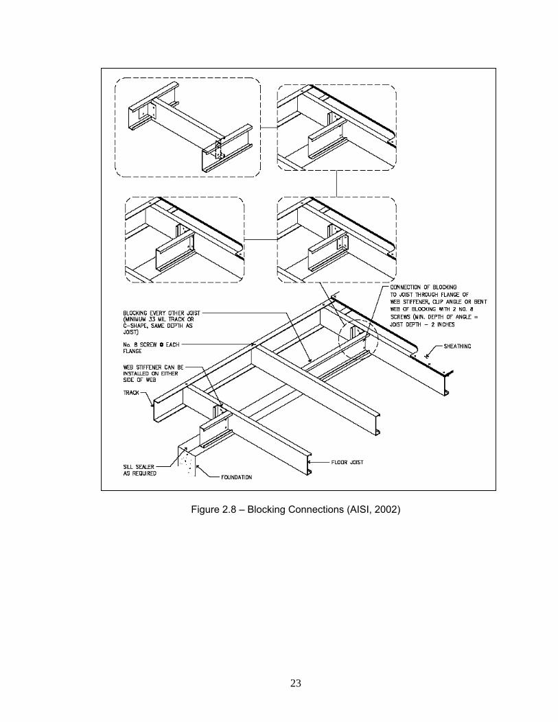
Figure 2.8 – Blocking Connections (AISI, 2002)
23
GABLE END WALL ASSEMBLYOR WALL STUDS
3 MIN12 MAX
12
ROOF SHEATHING
GABLE ENDWALL STUDS
SIDE WALLTRACK HEIGHT
WALL SHEATHING
FLOOR FRAMING
8', 9'
, OR
10'
STUD
HEI
GHT
8', 9'
, OR
10'
STUD
HEI
GHT
FOR
2-ST
ORY
RIDG
E HE
IGHT
(20'
MAX)
BUILDING WIDTH
STUD SPACING
Figure 2.9 - Gable End Wall Elevation for Gable End Wall Assembly Option
24
8', 9'
, OR
10'
STUD
HEI
GHT,
hFO
R 2-
STOR
YRE
F. T
ABLE
2.7
OR 2.
8
8', 9'
, OR
10'
STUD
HEI
GHT,
hRE
F. T
ABLE
2.7
EAVE FRAMING
ROOF SHEATHING
REF. FIGURE 2.12
DIAPHRAGM LENGTHREF. TABLES 2.3 - 2.6
GABLE ENDWALL STUDS
FLOORFRAMING
GYPSUM BOARD ORWOOD STRUCTURAL PANEL CEILING DIAPHRAGM
ROOF TRUSSESBY MANUFACTURER
STUD
HEI
GHT,
hRE
F. T
ABLE
2.1 O
R 2.2
(SEE
NOT
E 1)
ROOF TRUSSES OR GABLEEND WALL ASSEMBLY
Figure 2.10 – Wall Section for Gable End Wall Assembly
25
FLAT STRAP OR STUD BLOCKING @ 48" O.C.
LC TRUSS, TYP.
GABLE END WALL ASSEMBLY
GABLE END WALL STUDS
CONT. CLIP ANGLEW/#8 SCREWS @ 6"
O.C. BOTH LEGS
2-#8 SCREWS @ 6" O.C.
WOOD STRUCTURAL PANEL ORGYPSUM BOARD DIAPHRAGMREF. TABLES 2.3 - 2.6
DIAPHRAGM LENGTHREF. TABLES 2.3 - 2.6
#8 SCREWS @ 6" O.C.TO FLAT BLOCKING
Figure 2.11 - Ceiling Diaphragm to Gable End Wall for Roof Trusses
26
3 MIN12 MAX
RAFTER (BEYOND)
ROOF SHEATHING
12
STUD SPACING
WALL SHEATHING
FLOOR FRAMING
GABLE ENDWALL STUDS
8', 9'
, OR
10'
STUD
HEI
GHT
FOR
2-ST
ORY
STUD
HEI
GHT
- VAR
IES
BUILDING WIDTH
Figure 2.12 - Gable End Wall Elevation for Cathedral Ceiling Option
27
RAFTER
FLOOR FRAMING
ROOF SHEATHING
GABLE ENDWALL STUDS
REF. FIGURE 2.3ST
UD H
EIGH
T, h
(30'
MAX)
RE
F. T
ABLE
2.1 O
R 2.2
8', 9'
, OR
10'
STUD
HEI
GHT,
hFO
R 2-
STOR
YRE
F. T
ABLE
2.7
OR 2.
8
Figure 2.13 - Gable End Wall Section for Cathedral Ceiling Option
28
TRACK OR C-SHAPEC-SHAPES:600S162-43 FOR OPENINGS < 6'-0" WIDE800S162-54 FOR OPENINGS > 6'-0" WIDE
STUD
HEI
GHT,
hGABLE ENDWALL STUDS
BUILDING WIDTH
STUD SPACING
3 MIN12 MAX
12
CRIPPLE STUD
STUD
HEI
GHT,
h
NOTE 1: HEADER MAY BE BACK-TO-BACK OR BOX BEAM CONFIGURATION (SHOWN)REF. FIGURES 3.2 AND 3.3 FOR CONSTRUCTION.
HEAD TRACK SPAN, L REF. TABLES 3.2 - 3.6
KING STUD(S)REF. TABLE 3.1
HEAD TRACKREF. TABLES 3.2 - 3.6
JACK STUD(S)REF. TABLE 3.1
Figure 3.1 - Openings in Gable End Walls
29
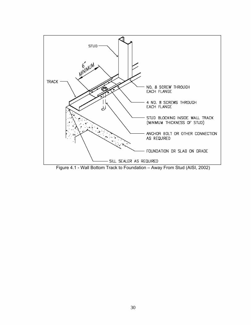
Figure 4.1 - Wall Bottom Track to Foundation – Away From Stud (AISI, 2002)
30
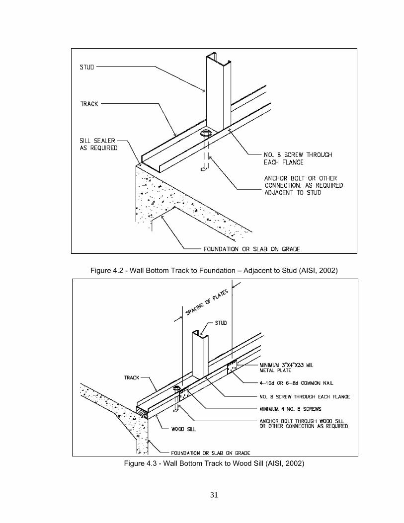
Figure 4.2 - Wall Bottom Track to Foundation – Adjacent to Stud (AISI, 2002)
Figure 4.3 - Wall Bottom Track to Wood Sill (AISI, 2002)
31
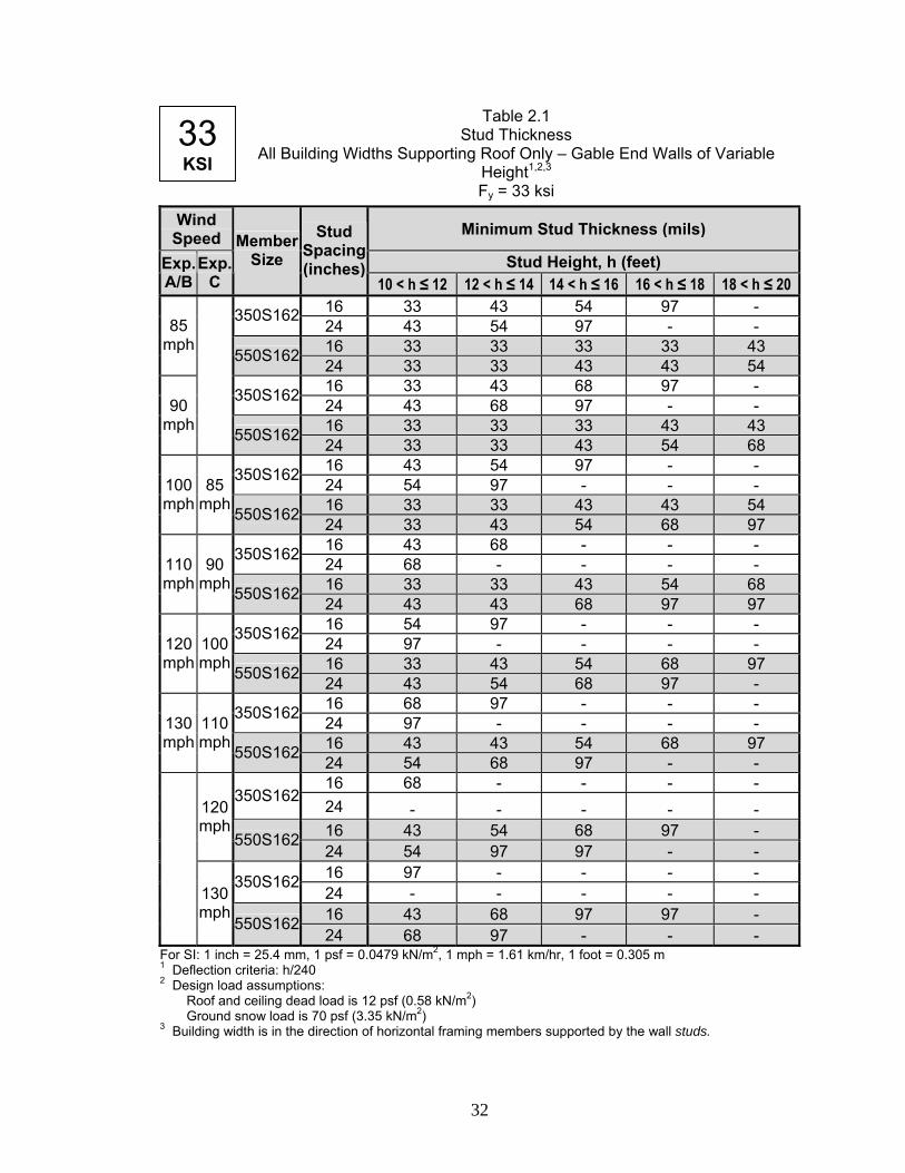
For SI: 1 inch = 25.4 mm, 1 psf = 0.0479 kN/m2, 1 mph = 1.61 km/hr, 1 foot = 0.305 m
Table 2.1 Stud Thickness
All Building Widths Supporting Roof Only – Gable End Walls of Variable Height1,2,3
Fy = 33 ksi
Wind Speed Minimum Stud Thickness (mils)
Stud Height, h (feet) Exp. A/B
Exp. C
Member Size
Stud Spacing (inches)
10 < h ≤ 12 12 < h ≤ 14 14 < h ≤ 16 16 < h ≤ 18 18 < h ≤ 20 16 33 43 54 97 - 350S162 24 43 54 97 - - 16 33 33 33 33 43
85 mph
550S162 24 33 33 43 43 54 16 33 43 68 97 - 350S162 24 43 68 97 - - 16 33 33 33 43 43
90 mph
550S162 24 33 33 43 54 68 16 43 54 97 - - 350S162 24 54 97 - - - 16 33 33 43 43 54
100 mph
85 mph 550S162 24 33 43 54 68 97
16 43 68 - - - 350S162 24 68 - - - - 16 33 33 43 54 68
110 mph
90 mph 550S162 24 43 43 68 97 97
16 54 97 - - - 350S162 24 97 - - - - 16 33 43 54 68 97
120 mph
100 mph 550S162 24 43 54 68 97 -
16 68 97 - - - 350S162 24 97 - - - - 16 43 43 54 68 97
130 mph
110 mph 550S162 24 54 68 97 - -
16 68 - - - - 350S162
24 - - - - - 16 43 54 68 97 -
120 mph
550S162 24 54 97 97 - - 16 97 - - - - 350S162 24 - - - - - 16 43 68 97 97 -
130 mph
550S162 24 68 97 - - -
33 KSI
1 Deflection criteria: h/240 2 Design load assumptions:
Roof and ceiling dead load is 12 psf (0.58 kN/m2) Ground snow load is 70 psf (3.35 kN/m2)
3 Building width is in the direction of horizontal framing members supported by the wall studs.
32
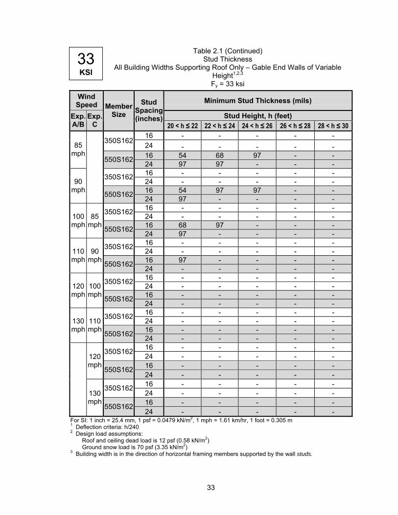
For SI: 1 inch = 25.4 mm, 1 psf = 0.0479 kN/m2, 1 mph = 1.61 km/hr, 1 foot = 0.305 m
Table 2.1 (Continued) Stud Thickness
All Building Widths Supporting Roof Only – Gable End Walls of Variable Height1,2,3
Fy = 33 ksi
Wind Speed Minimum Stud Thickness (mils)
Stud Height, h (feet) Exp. A/B
Exp. C
Member Size
Stud Spacing (inches)
20 < h ≤ 22 22 < h ≤ 24 24 < h ≤ 26 26 < h ≤ 28 28 < h ≤ 30 16 - - - - -
350S162 24 - - - - - 16 54 68 97 - -
85 mph
550S162 24 97 97 - - - 16 - - - - - 350S162 24 - - - - - 16 54 97 97 - -
90 mph
550S162 24 97 - - - - 16 - - - - - 350S162 24 - - - - - 16 68 97 - - -
100 mph
85 mph 550S162 24 97 - - - -
16 - - - - - 350S162 24 - - - - - 16 97 - - - -
110 mph
90 mph 550S162 24 - - - - -
16 - - - - - 350S162 24 - - - - - 16 - - - - -
120 mph
100 mph 550S162 24 - - - - -
16 - - - - - 350S162 24 - - - - - 16 - - - - -
130 mph
110 mph 550S162 24 - - - - -
16 - - - - - 350S162 24 - - - - - 16 - - - - -
120 mph
550S162 24 - - - - - 16 - - - - - 350S162 24 - - - - - 16 - - - - -
130 mph
550S162 24 - - - - -
33 KSI
1 Deflection criteria: h/240 2 Design load assumptions:
Roof and ceiling dead load is 12 psf (0.58 kN/m2) Ground snow load is 70 psf (3.35 kN/m2)
3 Building width is in the direction of horizontal framing members supported by the wall studs.
33
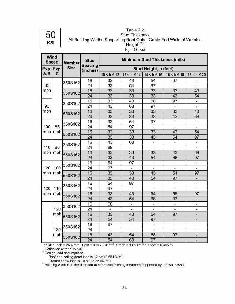
Table 2.2 Stud Thickness
All Building Widths Supporting Roof Only - Gable End Walls of Variable Height1,2,3
Fy = 50 ksi
Wind Speed Minimum Stud Thickness (mils)
Stud Height, h (feet) Exp. A/B
Exp. C
Member Size
Stud Spacing (inches)
10 < h ≤ 12 12 < h ≤ 14 14 < h ≤ 16 16 < h ≤ 18 18 < h ≤ 20 16 33 43 54 97 - 350S162 24 33 54 97 - - 16 33 33 33 33 43
85 mph
550S162 24 33 33 33 43 54 16 33 43 68 97 - 350S162 24 43 68 97 - - 16 33 33 33 33 43
90 mph
550S162 24 33 33 33 43 68 16 33 54 97 - - 350S162 24 54 97 - - - 16 33 33 33 43 54
100 mph
85 mph 550S162 24 33 33 43 54 97
16 43 68 - - - 350S162 24 68 - - - - 16 33 33 33 43 68
110 mph
90 mph 550S162 24 33 43 54 68 97
16 54 97 - - - 350S162 24 97 - - - - 16 33 33 43 54 97
120 mph
100 mph 550S162 24 33 43 54 97 -
16 54 97 - - - 350S162 24 97 - - - - 16 33 43 54 68 97
130 mph
110 mph 550S162 24 43 54 68 97 -
16 68 - - - - 350S162 24 - - - - - 16 33 43 54 97 -
120 mph 550S162 24 54 54 97 - -
16 97 - - - - 350S162 24 - - - - - 16 43 54 68 97 -
130 mph 550S162 24 54 68 97 - -
50 KSI
For SI: 1 inch = 25.4 mm, 1 psf = 0.0479 kN/m2, 1 mph = 1.61 km/hr, 1 foot = 0.305 m 1 Deflection criteria: h/240 2 Design load assumptions:
Roof and ceiling dead load is 12 psf (0.58 kN/m2) Ground snow load is 70 psf (3.35 kN/m2)
3 Building width is in the direction of horizontal framing members supported by the wall studs.
34

Table 2.2 (Continued) Stud Thickness
All Building Widths Supporting Roof Only - Gable End Walls of Variable Height1,2,3
Fy = 50 ksi
Wind Speed Minimum Stud Thickness (mils)
Stud Height, h (feet) Exp. A/B
Exp. C
Member Size
Stud Spacing (inches)
20 < h ≤ 22 22 < h ≤ 24 24 < h ≤ 26 26 < h ≤ 28 28 < h ≤ 30 16 - - - - - 350S162 24 - - - - - 16 54 68 97 - -
85 mph
550S162 24 97 97 - - - 16 - - - - - 350S162 24 - - - - - 16 54 97 97 - -
90 mph
550S162 24 97 - - - - 16 - - - - - 350S162 24 - - - - - 16 68 97 - - -
100 mph
85 mph 550S162 24 97 - - - -
16 - - - - - 350S162 24 - - - - - 16 97 - - - -
110 mph
90 mph 550S162 24 - - - - -
16 - - - - - 350S162 24 - - - - - 16 - - - - -
120 mph
100 mph 550S162 24 - - - - -
16 - - - - - 350S162 24 - - - - - 16 - - - - -
130 mph
110 mph 550S162 24 - - - - -
16 - - - - - 350S162 24 - - - - - 16 - - - - -
120 mph
550S162 24 - - - - - 16 - - - - - 350S162 24 - - - - - 16 - - - - -
130 mph
550S162 24 - - - - -
50 KSI
For SI: 1 inch = 25.4 mm, 1 psf = 0.0479 kN/m2, 1 mph = 1.61 km/hr, 1 foot = 0.305 m 1 Deflection criteria: h/240 2 Design load assumptions:
Roof and ceiling dead load is 12 psf (0.58 kN/m2) Ground snow load is 70 psf (3.35 kN/m2)
3 Building width is in the direction of horizontal framing members supported by the wall studs
35
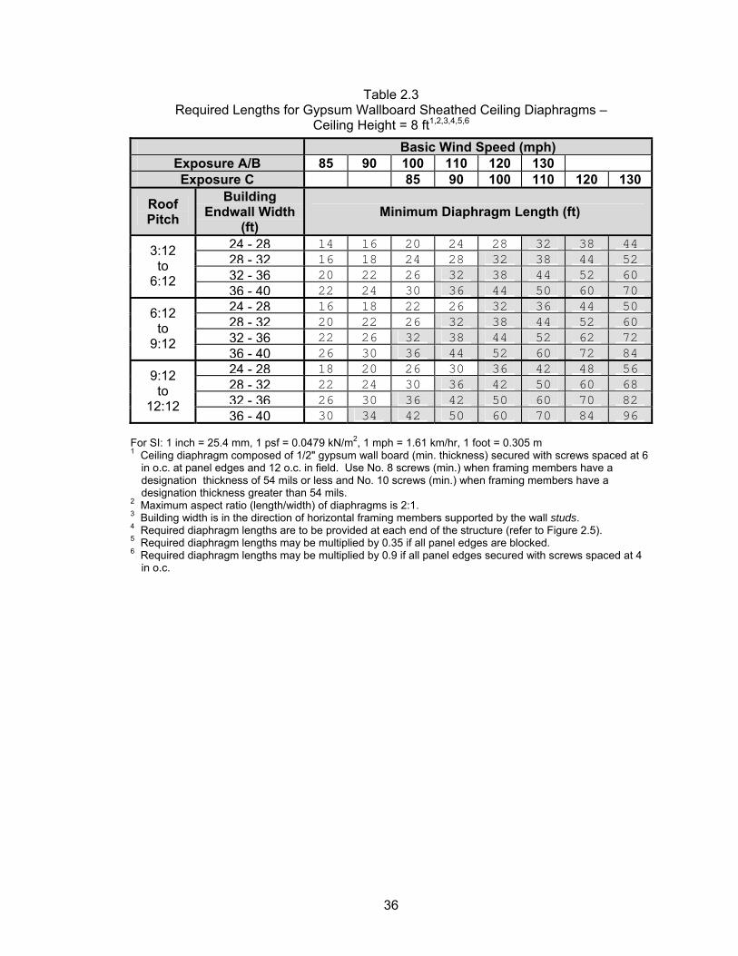
Table 2.3 Required Lengths for Gypsum Wallboard Sheathed Ceiling Diaphragms –
Ceiling Height = 8 ft1,2,3,4,5,6
Basic Wind Speed (mph) Exposure A/B 85 90 100 110 120 130 Exposure C 85 90 100 110 120 130
Roof Pitch
Building Endwall Width
(ft) Minimum Diaphragm Length (ft)
24 - 28 14 16 20 24 28 32 38 4428 - 32 16 18 24 28 32 38 44 5232 - 36 20 22 26 32 38 44 52 60
3:12 to
6:12 36 - 40 22 24 30 36 44 50 60 7024 - 28 16 18 22 26 32 36 44 5028 - 32 20 22 26 32 38 44 52 6032 - 36 22 26 32 38 44 52 62 72
6:12 to
9:12 36 - 40 26 30 36 44 52 60 72 8424 - 28 18 20 26 30 36 42 48 5628 - 32 22 24 30 36 42 50 60 6832 - 36 26 30 36 42 50 60 70 82
9:12 to
12:12 36 - 40 30 34 42 50 60 70 84 96
For SI: 1 inch = 25.4 mm, 1 psf = 0.0479 kN/m2, 1 mph = 1.61 km/hr, 1 foot = 0.305 m 1 Ceiling diaphragm composed of 1/2" gypsum wall board (min. thickness) secured with screws spaced at 6 in o.c. at panel edges and 12 o.c. in field. Use No. 8 screws (min.) when framing members have a
designation thickness of 54 mils or less and No. 10 screws (min.) when framing members have a designation thickness greater than 54 mils.
2 Maximum aspect ratio (length/width) of diaphragms is 2:1. 3 Building width is in the direction of horizontal framing members supported by the wall studs. 4 Required diaphragm lengths are to be provided at each end of the structure (refer to Figure 2.5). 5 Required diaphragm lengths may be multiplied by 0.35 if all panel edges are blocked. 6 Required diaphragm lengths may be multiplied by 0.9 if all panel edges secured with screws spaced at 4
in o.c.
36
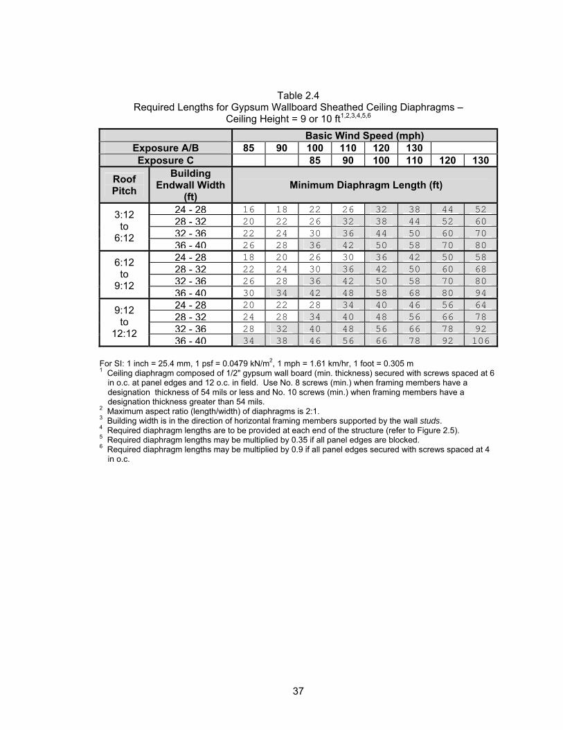
Table 2.4 Required Lengths for Gypsum Wallboard Sheathed Ceiling Diaphragms –
Ceiling Height = 9 or 10 ft1,2,3,4,5,6
Basic Wind Speed (mph) Exposure A/B 85 90 100 110 120 130 Exposure C 85 90 100 110 120 130
Roof Pitch
Building Endwall Width
(ft) Minimum Diaphragm Length (ft)
24 - 28 16 18 22 26 32 38 44 5228 - 32 20 22 26 32 38 44 52 6032 - 36 22 24 30 36 44 50 60 70
3:12 to
6:12 36 - 40 26 28 36 42 50 58 70 8024 - 28 18 20 26 30 36 42 50 5828 - 32 22 24 30 36 42 50 60 6832 - 36 26 28 36 42 50 58 70 80
6:12 to
9:12 36 - 40 30 34 42 48 58 68 80 9424 - 28 20 22 28 34 40 46 56 6428 - 32 24 28 34 40 48 56 66 7832 - 36 28 32 40 48 56 66 78 92
9:12 to
12:12 36 - 40 34 38 46 56 66 78 92 106
For SI: 1 inch = 25.4 mm, 1 psf = 0.0479 kN/m2, 1 mph = 1.61 km/hr, 1 foot = 0.305 m 1 Ceiling diaphragm composed of 1/2" gypsum wall board (min. thickness) secured with screws spaced at 6 in o.c. at panel edges and 12 o.c. in field. Use No. 8 screws (min.) when framing members have a
designation thickness of 54 mils or less and No. 10 screws (min.) when framing members have a designation thickness greater than 54 mils.
2 Maximum aspect ratio (length/width) of diaphragms is 2:1. 3 Building width is in the direction of horizontal framing members supported by the wall studs. 4 Required diaphragm lengths are to be provided at each end of the structure (refer to Figure 2.5). 5 Required diaphragm lengths may be multiplied by 0.35 if all panel edges are blocked. 6 Required diaphragm lengths may be multiplied by 0.9 if all panel edges secured with screws spaced at 4
in o.c.
37
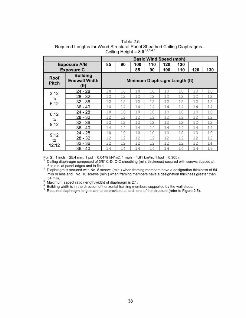
Table 2.5 Required Lengths for Wood Structural Panel Sheathed Ceiling Diaphragms –
Ceiling Height = 8 ft1,2,3,4,5
Basic Wind Speed (mph) Exposure A/B 85 90 100 110 120 130 Exposure C 85 90 100 110 120 130
Roof Pitch
Building Endwall Width
(ft) Minimum Diaphragm Length (ft)
24 - 28 10 10 10 10 10 10 10 1028 - 32 12 12 12 12 12 12 12 1232 - 36 12 12 12 12 12 12 12 12
3:12 to
6:12 36 - 40 14 14 14 14 14 14 14 1424 - 28 10 10 10 10 10 10 10 1028 - 32 12 12 12 12 12 12 12 1232 - 36 12 12 12 12 12 12 12 12
6:12 to
9:12 36 - 40 14 14 14 14 14 14 14 1424 - 28 10 10 10 10 10 10 10 1028 - 32 12 12 12 12 12 12 12 1232 - 36 12 12 12 12 12 12 12 14
9:12 to
12:12 36 - 40 14 14 14 14 14 14 14 16
For SI: 1 inch = 25.4 mm, 1 psf = 0.0479 kN/m2, 1 mph = 1.61 km/hr, 1 foot = 0.305 m 1 Ceiling diaphragm composed of 3/8" C-D, C-C sheathing (min. thickness) secured with screws spaced at 6 in o.c. at panel edges and in field. 2 Diaphragm is secured with No. 8 screws (min.) when framing members have a designation thickness of 54 mils or less and No. 10 screws (min.) when framing members have a designation thickness greater than 54 mils. 3 Maximum aspect ratio (length/width) of diaphragm is 2:1. 4 Building width is in the direction of horizontal framing members supported by the wall studs. 5 Required diaphragm lengths are to be provided at each end of the structure (refer to Figure 2.5).
38
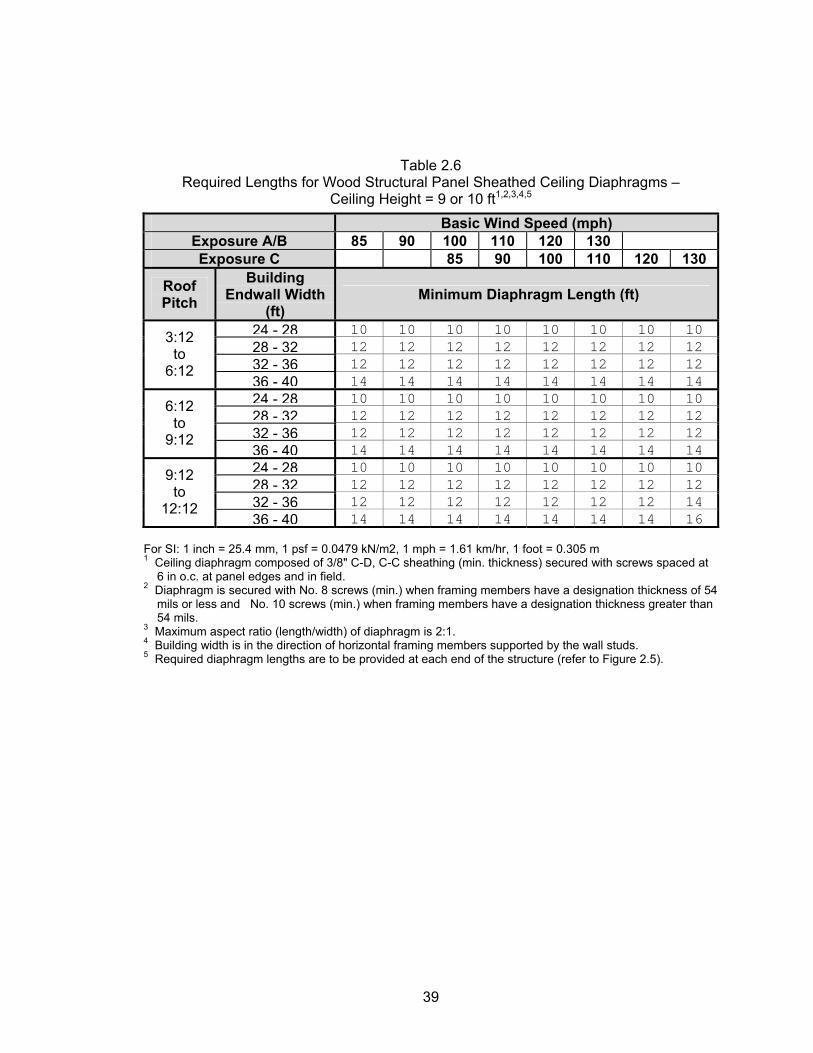
Table 2.6 Required Lengths for Wood Structural Panel Sheathed Ceiling Diaphragms –
Ceiling Height = 9 or 10 ft1,2,3,4,5
Basic Wind Speed (mph) Exposure A/B 85 90 100 110 120 130 Exposure C 85 90 100 110 120 130
Roof Pitch
Building Endwall Width
(ft) Minimum Diaphragm Length (ft)
24 - 28 10 10 10 10 10 10 10 1028 - 32 12 12 12 12 12 12 12 1232 - 36 12 12 12 12 12 12 12 12
3:12 to
6:12 36 - 40 14 14 14 14 14 14 14 1424 - 28 10 10 10 10 10 10 10 1028 - 32 12 12 12 12 12 12 12 1232 - 36 12 12 12 12 12 12 12 12
6:12 to
9:12 36 - 40 14 14 14 14 14 14 14 1424 - 28 10 10 10 10 10 10 10 1028 - 32 12 12 12 12 12 12 12 1232 - 36 12 12 12 12 12 12 12 14
9:12 to
12:12 36 - 40 14 14 14 14 14 14 14 16
For SI: 1 inch = 25.4 mm, 1 psf = 0.0479 kN/m2, 1 mph = 1.61 km/hr, 1 foot = 0.305 m 1 Ceiling diaphragm composed of 3/8" C-D, C-C sheathing (min. thickness) secured with screws spaced at 6 in o.c. at panel edges and in field. 2 Diaphragm is secured with No. 8 screws (min.) when framing members have a designation thickness of 54 mils or less and No. 10 screws (min.) when framing members have a designation thickness greater than 54 mils. 3 Maximum aspect ratio (length/width) of diaphragm is 2:1. 4 Building width is in the direction of horizontal framing members supported by the wall studs. 5 Required diaphragm lengths are to be provided at each end of the structure (refer to Figure 2.5).
39
For SI: 1 inch = 25.4 mm, 1 psf = 0.0479 kN/m2, 1 mph = 1.61 km/hr, 1 foot = 0.305 m
Table 2.7 Stud Thickness
All Building Widths – Gable End Stud Wall1,2,3
Fy = 33 ksi
Wind Speed Minimum Stud Thickness (mils)
Stud Height, h (feet) Exp. A/B
Exp. C
Member Size
Stud Spacing (inches)
8 9 10 16 33 33 33 350S162 24 33 33 33 16 33 33 33
85 mph
550S162 24 33 33 33 16 33 33 33 350S162 24 33 33 33 16 33 33 33
90 mph
550S162 24 33 33 33 16 33 33 33 350S162 24 33 33 43 16 33 33 33
100 mph
85 mph 550S162 24 33 33 33
16 33 33 33 350S162 24 33 33 33 16 33 33 33
110 mph
90 mph 550S162 24 33 33 33
16 33 33 33 350S162 24 43 33 43 16 33 33 33
120 mph
100 mph 550S162 24 33 33 33
16 33 33 33 350S162 24 33 43 54 16 33 33 33
130 mph
110 mph 550S162 24 33 33 33
16 43 54 68 350S162 24 68 97 97 16 33 33 43 120
mph 550S162 24 43 43 54 16 54 68 97 350S162 24 54 97 - 16 33 43 43 130
mph 550S162 24 43 43 43
33 KSI
1 Deflection criteria: h/240 2 Design load assumptions:
Roof and ceiling dead load is 12 psf (0.58 kN/m2) Ground snow load is 70 psf (3.35 kN/m2) Floor dead load is 10 psf (0.48 kN/m2) Floor live load is 40 psf (1.92 kN/m2)
3 Building width is in the direction of horizontal framing members supported by the wall studs.
40
41
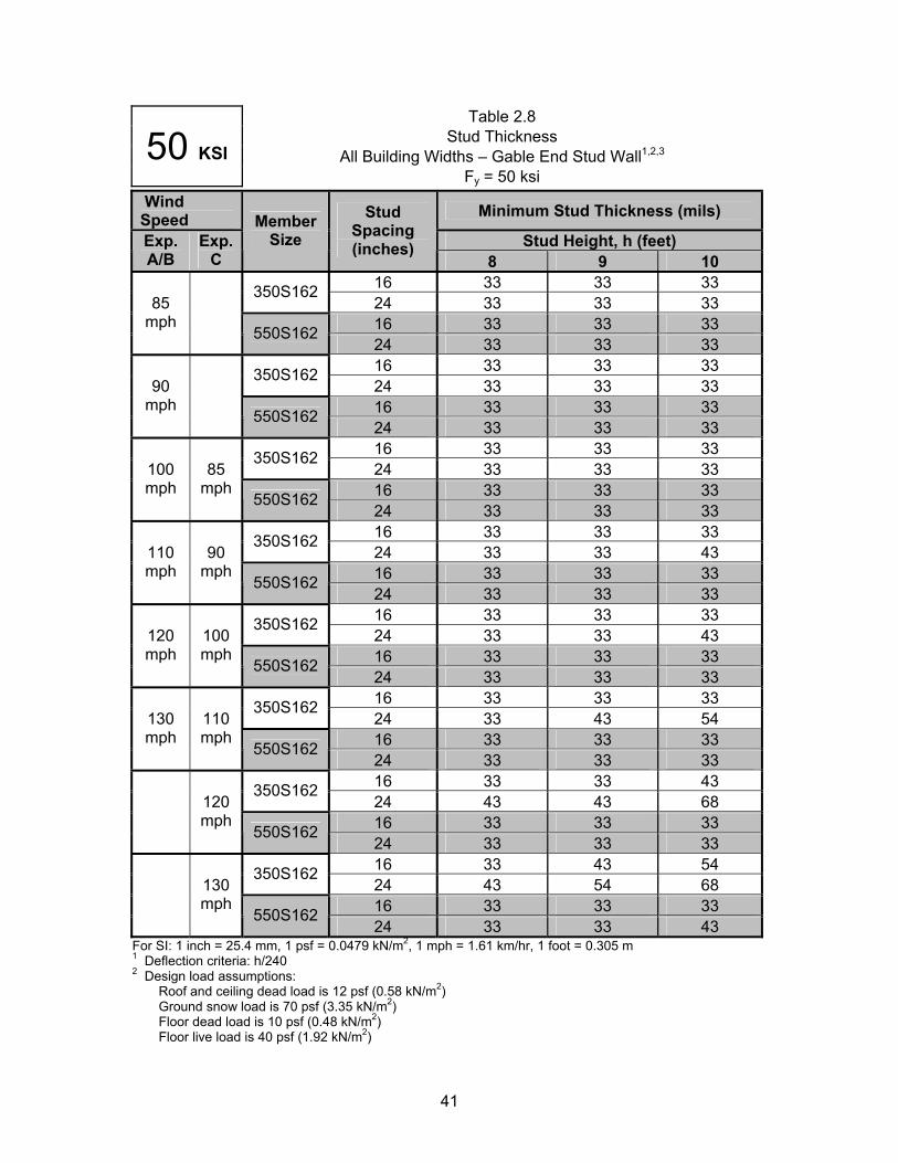
Table 2.8 Stud Thickness
All Building Widths – Gable End Stud Wall1,2,350 KSI Fy = 50 ksi
Wind Speed Minimum Stud Thickness (mils)
Stud Height, h (feet) Exp. A/B
Exp. C
Member Size
Stud Spacing (inches)
8 9 10 16 33 33 33 350S162 24 33 33 33 16 33 33 33
85 mph
550S162 24 33 33 33 16 33 33 33 350S162 24 33 33 33 16 33 33 33
90 mph
550S162 24 33 33 33 16 33 33 33 350S162 24 33 33 33 16 33 33 33
100 mph
85 mph
550S162 24 33 33 33 16 33 33 33 350S162 24 33 33 43 16 33 33 33
110 mph
90 mph
550S162 24 33 33 33 16 33 33 33 350S162 24 33 33 43 16 33 33 33
120 mph
100 mph
550S162 24 33 33 33 16 33 33 33 350S162 24 33 43 54 16 33 33 33
130 mph
110 mph
550S162 24 33 33 33 16 33 33 43 350S162 24 43 43 68 16 33 33 33
120 mph
550S162 24 33 33 33 16 33 43 54 350S162 24 43 54 68 16 33 33 33
130 mph
550S162 24 33 33 43
For SI: 1 inch = 25.4 mm, 1 psf = 0.0479 kN/m2, 1 mph = 1.61 km/hr, 1 foot = 0.305 m 1 Deflection criteria: h/240 2 Design load assumptions:
Roof and ceiling dead load is 12 psf (0.58 kN/m2) Ground snow load is 70 psf (3.35 kN/m2) Floor dead load is 10 psf (0.48 kN/m2) Floor live load is 40 psf (1.92 kN/m2)
3 Building width is in the direction of horizontal framing members supported by the wall studs.
Table 3.1 – Required Number of King and Jack Studs (AISI, 2002)
F
Table 3.2 Head Track Span for 14' Maximum Stud Height, h1,2,3
Fy = 33 ksi
E
1 2 3
33 KSI
or SI: 1 inch = 25.4 mm, 1 psf = 0.0479 kN/m2, 1 mph = 1.61 km/hr, 1 foot = 0.305 m
Basic Wind
Speed (mph)
Allowable Head Track Span, L
(ft-in.)
xposure Track Designation A/B C 350T125-33 350T125-43 350T125-54 550T125-33 550T125-43 550T125-5485 4’-7” 5’-6” 6’-4” 5’-11” 7’-4” 8’-9” 90
4’-4” 5’-2” 6’-0” 5’-7” 7’-0” 8’-4”
100 85 3’-11” 4’-8” 5’-4” 5’-0” 6’-3” 7’-5” 110 90 3’-7” 4’-3” 4’-11” 4’-7” 5’-8” 6’-9” 120 100 3’-3” 3’-10” 4’-6” 4’-2” 5’-3” 6’-2” 130 110 3’-0” 3’-7” 4’-2” 3’-10” 4’-10” 5’-9”
120 2’-9” 3’-3” 3’-9” 3’-6” 4’-5” 5’-3” 130 2’-6” 3’-0” 3’-6” 3’-3” 4’-1” 4’-10”
Deflection criteria: L/240 Stud height, h, measured from wall bottom track to wall top track or brace connection height at center of opening. Head track spans are based on components and cladding wind speeds and tributary span h/2.
42
F1 2 3
F
Table 3.3 Head Track Span for 18' Maximum Stud Height, h1,2,3
F = 33 ksi
E
E
1 2 3
33 KSI
or SI: 1 inch = 25.4 mm, 1 psf = 0.0479 kN/m2, 1 mph = 1.61 km/hr, 1 foot = 0.305 m Deflection criteria: L/240 Stud height, h, measured from wall bottom track to wall top track or brace connection height at center of opening.
Head track spans are based on components and cladding wind speeds and tributary span h/2.
43
or SI: 1 inch = 25.4 mm, 1 psf = 0.0479 kN/m2, 1 mph = 1.61 km/hr, 1 foot = 0.305 m
y
Basic Wind
Speed (mph)
Allowable Head Track Span, L
(ft-in.)
xposure Track Designation A/B C 350T125-33 350T125-43 350T125-54 550T125-33 550T125-43 550T125-5485 4’-1” 4’-10” 5’-7” 5’-3” 6’-6” 7’-9” 90 3’-10” 4’-7” 5’-3” 4’-11” 6’-2” 7’-4”
100 85 3’-5” 4’-4” 4’-9” 4’-5” 5’-6” 6’-6” 110 90 3’-2” 3’-9” 4’-4” 4’-0” 5’-0” 6’-0” 120 100 2’-10” 3’-5” 3’-11” 3’-8” 4’-7” 5’-6” 130 110 2’-8” 3’-2” 3’-8” 3’-5” 4’-3” 5’-1”
120 2’-5” 2’-10” 3’-4” 3’-1” 3’-10” 4’-7” 130 2’-3” 2’-8” 3’-1” 2’-10” 3’-7” 4’-3”
Table 3.4 Head Track Span for 22' Maximum Stud Height, h1,2,3
Fy = 33 ksi Basic Wind
Speed (mph)
Allowable Head Track Span, L
(ft-in.)
xposure Track Designation A/B C 350T125-33 350T125-43 350T125-54 550T125-33 550T125-43 550T125-5485 3’-8” 4’-4” 5’-1” 4’-9” 5’-10” 7’-0” 90 3’-6” 4’-2” 4’-9” 4’-6” 5’-7” 6’-7”
100 85 3’-1” 3’-8” 4’-3” 4’-0” 4’-11” 5’-11” 110 90 2’-10” 3’-4” 3’-11” 3’-8” 4’-6” 5’-5” 120 100 2’-7” 3’-1” 3’-7” 3’-4” 4’-2” 4’-11” 130 110 2’-5” 2’-10” 3’-4” 3’-1” 3’-10” 4’-7”
120 2’-2” 2’-7” 3’-0” 2’-10” 3’-6” 4’-2” 130 2’-0” 2’-5” 2’-9” 2’-7” 3’-3” 3’-10”
33 KSI
Deflection criteria: L/240 Stud height, h, measured from wall bottom track to wall top track or brace connection height at center of opening.
Head track spans are based on components and cladding wind speeds and tributary span h/2.
F1 2 3
F
Table 3.5 Head Track Span for 26' Maximum Stud Height, h1,2,3
F = 33 ksi
E
E
1 2 3
33 KSI
or SI: 1 inch = 25.4 mm, 1 psf = 0.0479 kN/m2, 1 mph = 1.61 km/hr, 1 foot = 0.305 m Deflection criteria: L/240 Stud height, h, measured from wall bottom track to wall top track or brace connection height at center of opening.
Head track spans are based on components and cladding wind speeds and tributary span h/2.
y
Basic Wind
Speed (mph)
Allowable Head Track Span, L
(ft-in.)
xposure Track Designation A/B C 350T125-33 350T125-43 350T125-54 550T125-33 550T125-43 550T125-5485 3’-5” 4’-0” 4’-8” 4’-4” 5’-5” 6’-5” 90 3’-12” 3’-9” 4’-5” 4’-1” 5’-1” 6’-1”
100 85 2’-10” 3’-5” 3’-11” 3’-8” 4’-7” 5’-5” 110 90 2’-7” 3’-1” 3’-7” 3’-4” 4’-2” 5’-0” 120 100 2’-5” 2’-10” 3’-3” 3’-1” 3’-10” 4’-7” 130 110 2’-2” 2’-7” 3’-0” 2’-10” 3’-6” 4’-2”
120 2’-0” 2’-5" 2’-9” 2’-7” 3’-3” 3’-10” 130 1’-10" 2’-2” 2’-7” 2’-5” 3’-0” 3’-6”
Table 3.6 Head Track Span for 30' Maximum Stud Height, h1,2,3
Fy = 33 ksi
33 KSIor SI: 1 inch = 25.4 mm, 1 psf = 0.0479 kN/m2, 1 mph = 1.61 km/hr, 1 foot = 0.305 m
Basic Wind
Speed (mph)
Allowable Head Track Span, L
(ft-in.)
xposure Track Designation A/B C 350T125-33 350T125-43 350T125-54 550T125-33 550T125-43 550T125-5485 3’-2” 3’-9” 4’-4” 4’-1” 5’-0” 6’-0” 90 3’-0” 3’-6” 4’-1” 3’-10” 4’-9” 5’-8”
100 85 2’-8” 3’-2” 3’-8” 3’-5” 4’-3” 5’-1” 110 90 2’-5” 2’-11” 3’-4” 3’-1” 3’-10” 4’-7” 120 100 2’-3” 2’-8” 3’-1” 2’-10” 3’-7” 4’-3” 130 110 2’-0” 2’-5” 2’-10” 2’-8” 3’-3” 3’-11”
120 1’-10” 2’-3” 2’-7” 2’-5” 3’-0” 3’-7” 130 1’-9” 2’-1” 2’-4” 2’-3” 2’-9” 3’-3”
Deflection criteria: L/240 Stud height, h, measured from wall bottom track to wall top track or brace connection height at center of opening. Head track spans are based on components and cladding wind speeds and tributary span h/2.
44
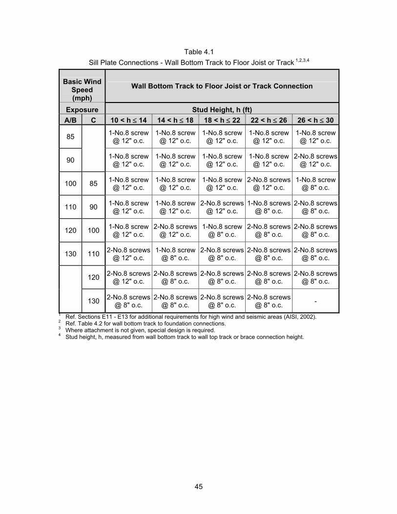
Table 4.1 Sill Plate Connections - Wall Bottom Track to Floor Joist or Track 1,2,3,4
Basic Wind Speed (mph)
Wall Bottom Track to Floor Joist or Track Connection
Exposure Stud Height, h (ft) A/B C 10 < h ≤ 14 14 < h ≤ 18 18 < h ≤ 22 22 < h ≤ 26 26 < h ≤ 30
85 1-No.8 screw @ 12" o.c.
1-No.8 screw @ 12" o.c.
1-No.8 screw @ 12" o.c.
1-No.8 screw @ 12" o.c.
1-No.8 screw @ 12" o.c.
90
1-No.8 screw
@ 12" o.c. 1-No.8 screw
@ 12" o.c. 1-No.8 screw
@ 12" o.c. 1-No.8 screw
@ 12" o.c. 2-No.8 screws
@ 12" o.c.
100 85 1-No.8 screw @ 12" o.c.
1-No.8 screw @ 12" o.c.
1-No.8 screw @ 12" o.c.
2-No.8 screws @ 12" o.c.
1-No.8 screw @ 8" o.c.
110 90 1-No.8 screw @ 12" o.c.
1-No.8 screw @ 12" o.c.
2-No.8 screws @ 12" o.c.
1-No.8 screws @ 8" o.c.
2-No.8 screws @ 8" o.c.
120 100 1-No.8 screw @ 12" o.c.
2-No.8 screws @ 12" o.c.
1-No.8 screw @ 8" o.c.
2-No.8 screws @ 8" o.c.
2-No.8 screws @ 8" o.c.
130 110 2-No.8 screws @ 12" o.c.
1-No.8 screw @ 8" o.c.
2-No.8 screws @ 8" o.c.
2-No.8 screws @ 8" o.c.
2-No.8 screws @ 8" o.c.
120 2-No.8 screws @ 12" o.c.
2-No.8 screws @ 8" o.c.
2-No.8 screws @ 8" o.c.
2-No.8 screws @ 8" o.c.
2-No.8 screws @ 8" o.c.
130 2-No.8 screws @ 8" o.c.
2-No.8 screws @ 8" o.c.
2-No.8 screws @ 8" o.c.
2-No.8 screws @ 8" o.c. -
1 Ref. Sections E11 - E13 for additional requirements for high wind and seismic areas (AISI, 2002). 2 Ref. Table 4.2 for wall bottom track to foundation connections. 3 Where attachment is not given, special design is required. 4 Stud height, h, measured from wall bottom track to wall top track or brace connection height.
45
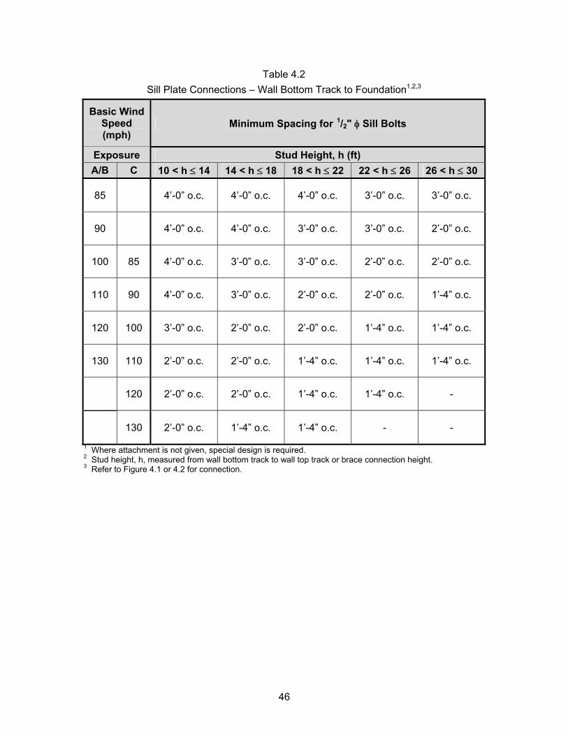
Table 4.2 Sill Plate Connections – Wall Bottom Track to Foundation1,2,3
Basic Wind Speed (mph)
Minimum Spacing for 1/2" φ Sill Bolts
Exposure Stud Height, h (ft) A/B C 10 < h ≤ 14 14 < h ≤ 18 18 < h ≤ 22 22 < h ≤ 26 26 < h ≤ 30
85 4’-0” o.c. 4’-0” o.c. 4’-0” o.c. 3’-0” o.c. 3’-0” o.c.
90 4’-0” o.c. 4’-0” o.c. 3’-0” o.c. 3’-0” o.c. 2’-0” o.c.
100 85 4’-0” o.c. 3’-0” o.c. 3’-0” o.c. 2’-0” o.c. 2’-0” o.c.
110 90 4’-0” o.c. 3’-0” o.c. 2’-0” o.c. 2’-0” o.c. 1’-4” o.c.
120 100 3’-0” o.c. 2’-0” o.c. 2’-0” o.c. 1’-4” o.c. 1’-4” o.c.
130 110 2’-0” o.c. 2’-0” o.c. 1’-4” o.c. 1’-4” o.c. 1’-4” o.c.
120 2’-0” o.c. 2’-0” o.c. 1’-4” o.c. 1’-4” o.c. -
130 2’-0” o.c. 1’-4” o.c. 1’-4” o.c. - -
1 Where attachment is not given, special design is required. 2 Stud height, h, measured from wall bottom track to wall top track or brace connection height. 3 Refer to Figure 4.1 or 4.2 for connection.
46
REFERENCES
American Concrete Institute (ACI) (2002), Building Code Requirements for Structural Concrete and Commentary, ACI 318-02; ACI 318R-02, Farmington Hills, MI, August. American Forest and Paper Association (AF&PA) (2001), National Design Specification for Wood Construction (2001 Edition) and Supplement: Design Values, AF&PA, Washington, D.C. American Forest and Paper Association/ American Society of Civil Engineers (AF&PA/ASCE) (1995), LRFD Manual for Engineered Wood Construction, AF&PA/ASCE 16-95, Washington, D.C. American Institute of Steel Construction (AISC) (2001), Manual of Steel Construction – Load and Resistance Factor Design, 3rd Edition, AISC, Chicago, IL, November. American Iron and Steel Institute (AISI) (1996), Design Guide for AISI Cold-Formed Steel Specification, AISI, Washington, D.C. American Iron and Steel Institute (AISI) (2000), Wind Design of Cold-Formed Steel Studs - AISI Position Paper - Draft, AISI, Washington D.C., February. American Iron and Steel Institute (AISI) (2001), North American Specification for the Design of Cold-Formed Steel Structural Members, AISI, Washington, D.C., December. American Iron and Steel Institute (AISI) (2002), Standard for Cold-Formed Steel Framing – Prescriptive Method for One and Two Family Dwellings, AISI, Washington, D.C., February. American Iron and Steel Institute (AISI) (2003), Commentary on the Standard for Cold-Formed Steel Framing – Prescriptive Method for One and Two Family Dwellings, AISI, Washington, D.C., December. American Iron and Steel Institute (AISI) (2004a), AISI Standard for Cold-Formed Steel Framing – Wall Stud Design - Draft for Public Review Only, AISI, Washington, D.C., July. American Iron and Steel Institute (AISI) (2004b), AISI Standard for Cold-Formed Steel Framing – Lateral Design - Draft for Public Review Only, AISI, Washington, D.C., July. APA – The Engineered Wood Association (APA) (2004), Panel Design Specification, APA, Tacoma, WA, March. American Society of Civil Engineers (ASCE) (1998), Minimum Design Loads for Buildings and Other Structures, ASCE 7-98, New York, NY. American Society of Civil Engineers (ASCE) (2002), Minimum Design Loads for Buildings and Other Structures, ASCE 7-02, New York, NY. RSG Software (RSG) (2003a), CFS Version 4.13, RSG Software, Inc., Lee’s Summit, MO.
47
RSG Software (RSG) (2003b), CFS411.dll, RSG Software, Inc., Lee’s Summit, MO. International Code Council (ICC) (2000), International Building Code, ICC, Falls Church, VA. North American Steel Framing Alliance (NASFA) (2000), Prescriptive Method for Residential Cold-Formed Steel Framing, NASFA, Washington, D.C., October. Stalnaker, Judith J., and Harris, Ernest C. (1999), Structural Design in Wood, 2nd Edition, Kluwer Academic Publishers. Yu, Wei-Wen (2000). Cold-Formed Steel Design, 3rd Edition, New York, NY, John Wiley & Sons, Inc.
48
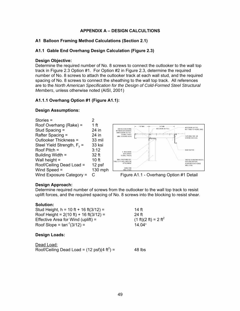
APPENDIX A – DESIGN CALCULTIONS A1 Balloon Framing Method Calculations (Section 2.1) A1.1 Gable End Overhang Design Calculation (Figure 2.3) Design Objective: Determine the required number of No. 8 screws to connect the outlooker to the wall top track in Figure 2.3 Option #1. For Option #2 in Figure 2.3, determine the required number of No. 8 screws to attach the outlooker track at each wall stud, and the required spacing of No. 8 screws to connect the sheathing to the wall top track. All references are to the North American Specification for the Design of Cold-Formed Steel Structural Members, unless otherwise noted (AISI, 2001) A1.1.1 Overhang Option #1 (Figure A1.1): Design Assumptions: Stories = 2 Roof Overhang (Rake) = 1 ft
#8 SCREWS @ 6" O.C.1'-0" MIN1'-0" MAX
#8 SCREWS @ 6" O.C.REF. TABLE F2-10 (AISI, 2002)
GABLE END WALL STUDS
4 - #8 SCREWS(OUTLOOKER
TO WALL TRACK)
350S162-33 BLOCKINGBETWEEN OUTLOOKERSW/#8 SCREWS @ 6" O.C.
TO WALL TRACK(MIN. 3 SCREWS EACH)
WALL SHEATHING REF.TABLE E3-11 (AISI, 2002) FOR
ATTACHMENT
350S162-33 (W/0 WEB HOLES)OUTLOOK RAFTERS. ALIGN WITH EACH GABLE WALL STUD
ROOF RAFTER
CLIP ANGLE W/2 - #8 SCREWS EACH LEG
Stud Spacing = 24 in Rafter Spacing = 24 in Outlooker Thickness = 33 mil Steel Yield Strength, Fy = 33 ksi Roof Pitch = 3:12 Building Width = 32 ft Wall height = 10 ft Roof/Ceiling Dead Load = 12 psf Wind Speed = 130 mph Wind Exposure Category = C Figure A1.1 - Overhang Option #1 Detail Design Approach: Determine required number of screws from the outlooker to the wall top track to resist uplift forces, and the required spacing of No. 8 screws into the blocking to resist shear. Solution: Stud Height, h = 10 ft + 16 ft(3/12) = 14 ft Roof Height = 2(10 ft) + 16 ft(3/12) = 24 ft Effective Area for Wind (uplift) = (1 ft)(2 ft) = 2 ft2
Roof Slope = tan-1(3/12) = 14.04° Design Loads: Dead Load: Roof/Ceiling Dead Load = (12 psf)(4 ft2) = 48 lbs
49
Wind Loads (Shear): Wind loads are calculated in accordance with ASCE 7-2002 Method 2 for Components and Cladding (C&C) (ASCE, 2002). Equation: Comments: Reference:
( ) ( )h p pip q GC GC⎡ ⎤= −⎣ ⎦
dV I
=
−
Low-Rise Building 6.5.12.4, Eq. 6-22 20.00256h z ztq K K K= (lb/ft2) 6.5.10, Eq 6-15
Where: Kz = 0.932 Exp. C, Case 1, z = 24 ft Table 6-3 Kzt = 1.0 No Topographic Factor Kd = 0.85 Table 6-4 V = 130 mph 3-Second Gust Wind Speed I = 1.0 Residential Building (Cat I) Table 1-1, Table 6-1
20.00256(0.932)(1.0)(0.85)(130) (1.0) 34.27hq = = lb/ft2
GCp = -1.1, +1.0 Assume Eff. Area < 10 ft2 Figure 6-11A GCpi = ±0.18 Enclosed Building
( ) ( )2(34.27 / ) 1.0 0.18 40.44p lb ft+ ⎡ ⎤= − −⎣ ⎦ lb/ft2
( ) ( )2(34.27 / ) 1.10 0.18 43.87p lb ft− ⎡ ⎤= − − =⎣ ⎦ lb/ft2 Controls Wind Loads (Uplift): Wind loads are calculated in accordance with ASCE 7-2002 Method 2 for Components and Cladding (C&C) (ASCE, 2002). Equation: Comments: Reference:
( ) ( )h p pip q GC GC⎡ ⎤= −⎣ ⎦
dV I
Low-Rise Building 6.5.12.4, Eq. 6-22 20.00256h z ztq K K K= (lb/ft2) 6.5.10, Eq 6-15
Where: Kz = 0.932 Exp. C, Case 1, z = 24 ft Table 6-3 Kzt = 1.0 No Topographic Factor Kd = 0.85 Table 6-4 V = 130 mph 3-Second Gust Wind Speed I = 1.0 Residential Building (Cat I) Table 1-1, Table 6-1
20.00256(0.932)(1.0)(0.85)(130) (1.0) 34.27hq = = lb/ft2
GCp = -3.7 Overhang, Area = 2 ft2 Figure 6-11C GCpi = 0 No Interior Surface
[ ]2(34.27 / ) 3.7 126.81p lb ft− = − = − lb/ft2 Controls Load Combinations: 1. 0.9D + 1.6W Uplift Check 2. 1.6W Shear Check
50
Design Loads: 1. Maximum Uplift, Pu = 0.9(48 lbs) – 1.6(126.81 psf)(2 ft2) = -362.6 lbs 2. Maximum Shear, wu = 1.6(43.87 psf)(14 ft/2) = 491.3 plf Material Properties: Fy (track and outlooker) = 33,000 psi Fu (track and outlooker) = 45,000 psi Tensile Capacity of No. 8 Screws: Must check pull-out, pull-over, and tension capacity of screws per Specification, Section E4.4: Pull-Out Capacity (Section E4.4.1):
20.85not c uP t dF=
lbs
Eq. E4.4.1-1 where tc = t2 = 0.0346 in 33 mil material d = 0.164 in No. 8 screw Fu2 = 45,000 psi 33 ksi steel
0.85(0.0346 )(0.164 )(45,000 ) 217.05notP in in psi= = Pull-Over Capacity (Section E4.4.2):
1 11.5nov w uP t d F=
lbs
Eq. E4.4.2-1 where t1 = 0.0346 in 33 mil material dw = 0.322 in No. 8 screw Fu1 = 45,000 psi 33 ksi steel
1.5(0.0346 )(0.322 )(45,000 ) 752.03novP in in psi= = Tension in Screw Capacity (Section E4.4.3): Assume tensile capacity of screw is exceeds pullout capacity of 33 mil material Therefore, Pn = Pnot = 217.05 lbs Determine Required Number of Screws:
0.50nP Puφ
φ≥
= Section E4
362.6 3.34
0.5(217.05 )u
n
P lbsN SP lbsφ
= = = crews - Need 4 Screws
Therefore, use minimum of 4 – No. 8 screws at each outlooker to wall top track connection as indicated in Figure 2.3.
51
No. 8 Screw Shear Capacity (Section E4.3): Connection Shear Limited by Tilting and Bearing (Section E4.3.1):
1 2 0.0346t t in= = 33 mil Material d = 0.164 in No. 8 Screw per Table C-E4-1
1 2 45,000u uF F ps= = i 33 ksi Steel
2
1
1.0tt
=
Therefore, nominal shear strength, Pns, is the smallest of the following:
3 32 24.2 4.2 (0.0346) (0.164)(45,000) 492.6ns uP t d F= = = lbs
bsbs
bs
Eq. E4.3.1-1
1 12.7 2.7(0.0346)(0.164)(45,000) 689.4ns uP t dF l= = = Eq. E4.3.1-2
2 22.7 2.7(0.0346)(0.164)(45,000) 689.4ns uP t dF l= = = Eq. E4.3.1-3
492.6nsP l= Connection Shear Limited by End Distance (Section E4.3.2): Assume end distance > 1.5d = 1.5(0.164 in) = 0.25 in Therefore, shear capacity will not be limited by end distance Shear in Screws (Section E4.3.3): Assume shear capacity of screw is exceeds tilting/bearing capacity of 33 mil material Therefore, Pns = 492.6 lbs Determine Required Spacing of Screws:
0.50ns uP Pφ
φ≥
= Section E4
0.5(492.6 ), (0.50 )(12 / ) 6
491.3n
u
P lbsSpacing s ft in ft inw plf
φ= = = =
Therefore, use No. 8 screws at 6” o.c. to connect blocking to wall track, as shown in Figure 2.3, Option #1.
52
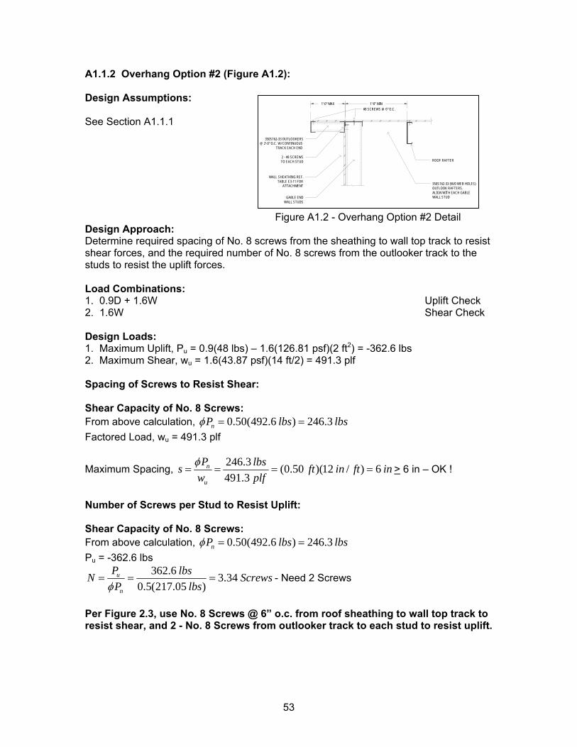
A1.1.2 Overhang Option #2 (Figure A1.2): Design Assumptions:
350S162-33 (W/0 WEB HOLES)OUTLOOK RAFTERS. ALIGN WITH EACH GABLE WALL STUD
ROOF RAFTER2 - #8 SCREWSTO EACH STUD
350S162-33 OUTLOOKERS @ 2'-0" O.C. W/ CONTINUOUS
TRACK EACH END
#8 SCREWS @ 6" O.C.1'-0" MIN1'-0" MAX
GABLE END WALL STUDS
WALL SHEATHING REF.TABLE E3-11 FOR
ATTACHMENT
See Section A1.1.1 Figure A1.2 - Overhang Option #2 Detail Design Approach: Determine required spacing of No. 8 screws from the sheathing to wall top track to resist shear forces, and the required number of No. 8 screws from the outlooker track to the studs to resist the uplift forces. Load Combinations: 1. 0.9D + 1.6W Uplift Check 2. 1.6W Shear Check Design Loads: 1. Maximum Uplift, Pu = 0.9(48 lbs) – 1.6(126.81 psf)(2 ft2) = -362.6 lbs 2. Maximum Shear, wu = 1.6(43.87 psf)(14 ft/2) = 491.3 plf Spacing of Screws to Resist Shear: Shear Capacity of No. 8 Screws: From above calculation, 0.50(492.6 ) 246.3nP lbs lbsφ = = Factored Load, wu = 491.3 plf
Maximum Spacing, 246.3 (0.50 )(12 / ) 6491.3
n
u
P lbss ftw plf
in ft inφ= = = = > 6 in – OK !
Number of Screws per Stud to Resist Uplift: Shear Capacity of No. 8 Screws: From above calculation, 0.50(492.6 ) 246.3nP lbs lbsφ = = Pu = -362.6 lbs
362.6 3.340.5(217.05 )
u
n
P lbsN SP lbsφ
= = = crews - Need 2 Screws
Per Figure 2.3, use No. 8 Screws @ 6” o.c. from roof sheathing to wall top track to resist shear, and 2 - No. 8 Screws from outlooker track to each stud to resist uplift.
53
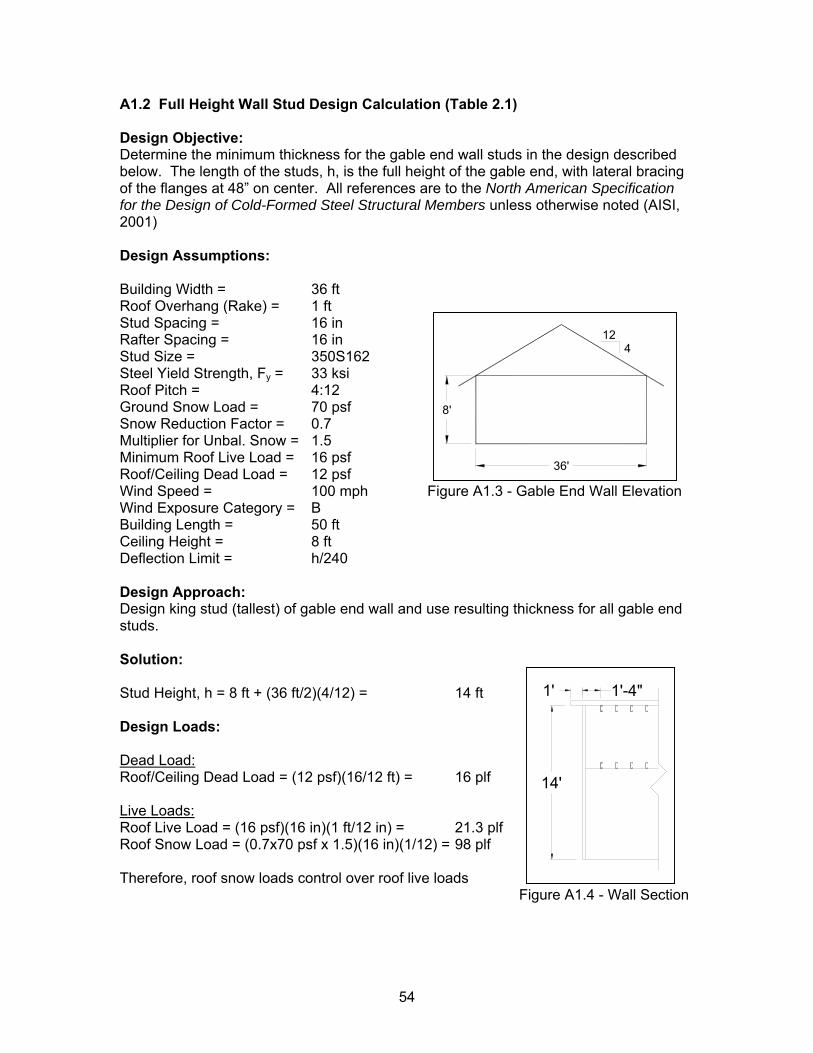
A1.2 Full Height Wall Stud Design Calculation (Table 2.1)
Design Objective: Determine the minimum thickness for the gable end wall studs in the design described below. The length of the studs, h, is the full height of the gable end, with lateral bracing of the flanges at 48” on center. All references are to the North American Specification for the Design of Cold-Formed Steel Structural Members unless otherwise noted (AISI, 2001) Design Assumptions: Building Width = 36 ft Roof Overhang (Rake) = 1 ft
4
8'
36'
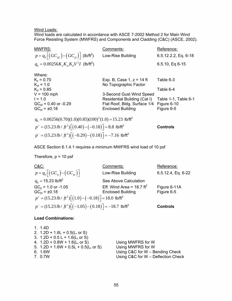
12Stud Spacing = 16 in Rafter Spacing = 16 in Stud Size = 350S162 Steel Yield Strength, Fy = 33 ksi Roof Pitch = 4:12 Ground Snow Load = 70 psf Snow Reduction Factor = 0.7 Multiplier for Unbal. Snow = 1.5 Minimum Roof Live Load = 16 psf Roof/Ceiling Dead Load = 12 psf Wind Speed = 100 mph Figure A1.3 - Gable End Wall Elevation Wind Exposure Category = B Building Length = 50 ft Ceiling Height = 8 ft Deflection Limit = h/240 Design Approach: Design king stud (tallest) of gable end wall and use resulting thickness for all gable end studs. Solution: Stud Height, h = 8 ft + (36 ft/2)(4/12) = 14 ft Design Loads: Dead Load: Roof/Ceiling Dead Load = (12 psf)(16/12 ft) = 16 plf
1' 1'-4"
14'
Live Loads: Roof Live Load = (16 psf)(16 in)(1 ft/12 in) = 21.3 plf Roof Snow Load = (0.7x70 psf x 1.5)(16 in)(1/12) = 98 plf Therefore, roof snow loads control over roof live loads Figure A1.4 - Wall Section
54
Wind Loads: Wind loads are calculated in accordance with ASCE 7-2002 Method 2 for Main Wind Force Resisting System (MWFRS) and Components and Cladding (C&C) (ASCE, 2002). MWFRS: Comments: Reference:
( ) ( )h pf pip q GC GC⎡ ⎤= −⎣ ⎦
dV I
⎤ =⎦= −
(lb/ft2) Low-Rise Building 6.5.12.2.2, Eq. 6-18 20.00256h z ztq K K K= (lb/ft2) 6.5.10, Eq 6-15
Where: Kz = 0.70 Exp. B, Case 1, z = 14 ft Table 6-3 Kzt = 1.0 No Topographic Factor Kd = 0.85 Table 6-4 V = 100 mph 3-Second Gust Wind Speed I = 1.0 Residential Building (Cat I) Table 1-1, Table 6-1 GCpf = 0.40 or -0.29 Flat Roof, Bldg. Surface 1/4 Figure 6-10 GCpi = ±0.18 Enclosed Building Figure 6-5
20.00256(0.70)(1.0)(0.85)(100) (1.0) 15.23hq = = lb/ft2
( ) ( )2(15.23 / ) 0.40 0.18 8.8p lb ft+ ⎡= − −⎣ lb/ft2 Controls
( ) ( )2(15.23 / ) 0.29 0.18 7.16p lb ft− ⎡ ⎤= − −⎣ ⎦ lb/ft2
ASCE Section 6.1.4.1 requires a minimum MWFRS wind load of 10 psf Therefore, p = 10 psf C&C: Comments: Reference:
( ) ( )h p pip q GC GC⎡ ⎤= −⎣ ⎦
=
= −
Low-Rise Building 6.5.12.4, Eq. 6-22
hq = 15.23 lb/ft2 See Above Calculation GCp = 1.0 or -1.05 Eff. Wind Area = 18.7 ft2 Figure 6-11A GCpi = ±0.18 Enclosed Building Figure 6-5
( ) ( )2(15.23 / ) 1.0 0.18 18.0p lb ft+ ⎡ ⎤= − −⎣ ⎦ lb/ft2
( ) ( )2(15.23 / ) 1.05 0.18 18.7p lb ft− ⎡ ⎤= − −⎣ ⎦ lb/ft2 Controls Load Combinations: 1. 1.4D 2. 1.2D + 1.6L + 0.5(Lr or S) 3. 1.2D + 0.5 L + 1.6(Lr or S) 4. 1.2D + 0.8W + 1.6(Lr or S) Using MWFRS for W 5. 1.2D + 1.6W + 0.5L + 0.5(Lr or S) Using MWFRS for W 6. 1.6W Using C&C for W – Bending Check 7. 0.7W Using C&C for W – Deflection Check
55
Design Loads: Reaction at Wall Stud = (2.33 ft x w)(1.17 ft)/1.33 ft = (2.04 ft)w See Figure A1.4
Axial Loads: Lateral Loads:1. 1.4(16 plf) = 22.4 plf None 2. 1.2(16 plf) + 1.6(0) + 0.5(98 plf) = 68.2 plf None 3. 1.2(16 plf) + 0.5 (0) + 1.6(98 plf) = 176 plf None 4. 1.2(16 plf) + 1.6(98 plf) = 176 plf 0.8(10 psf)(16/12) = 10.7 plf 5. 1.2(16 plf) + 0.5(98 plf) = 68.2 plf 1.6(10 psf)(16/12) = 21.3 plf 6. None 1.6(18.7 psf)(16/12) = 39.9 plf 7. None 0.7(18.7 psf)(16/12) = 17.5 plf Controlling Load Combinations:
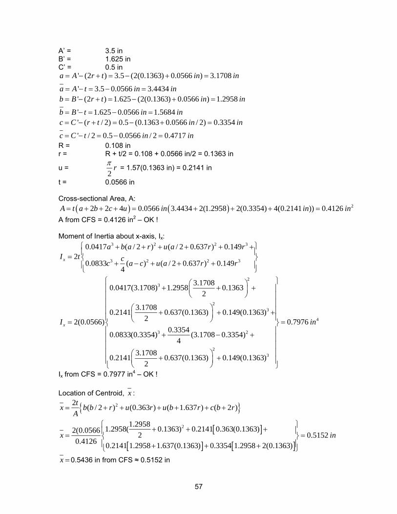
Axial Loads: Lateral Loads:3. (2.04 ft)(176 plf) = 359 lbs None 4. (2.04 ft)(176plf) = 359 lbs 10.7 plf 5. (2.04 ft)(68.2 plf) = 139.1 lbs 21.3 plf 6. None 39.9 plf 7. None 17.5 plf Material Properties: Fy = 33,000 psi E = 29,500,000 psi G = 11,300 psi µ = 0.30 (Poisson’s Ratio) Full Section Properties: Select a 350S162-54 section as indicated in Table 3.2. Section property calculations based on Design Guide for AISI Cold-Formed Steel Specification, Section 3 (AISI, 1996). Refer to Figure A1.4 for all section property calculations
Figure A1.5 - C-Section Dimensions
56
A’ = 3.5 in B’ = 1.625 in C’ = 0.5 in
' (2 ) 3.5 (2(0.1363) 0.0566 ) 3.1708
' 3.5 0.0566 3.4434
a A r t in in
a A t in in
= − + = − + =
= − = − =
' (2 ) 1.625 (2(0.1363) 0.0566 ) 1.2958
' 1.625 0.0566 1.5684
b B r t in in
b B t in in
= − + = − + =
= − = − =
' ( / 2) 0.5 (0.1363 0.0566 / 2) 0.3354
' / 2 0.5 0.0566 / 2 0.4717
c C r t in in
c C t in in
= − + = − + =
= − = − =
R = 0.108 in r = R + t/2 = 0.108 + 0.0566 in/2 = 0.1363 in
u = 2
rπ = 1.57(0.1363 in) = 0.2141 in
t = 0.0566 in Cross-sectional Area, A:
( ) ( ) 22 2 4 0.0566 3.4434 2(1.2958 2(0.3354) 4(0.2141 )) 0.4126A t a b c u in in in= + + + = + + + =A from CFS = 0.4126 in2 – OK ! Moment of Inertia about x-axis, Ix:
3 2 2 3
3 2 2 3
23
2
0.0417 ( / 2 ) ( / 2 0.637 ) 0.1492
0.0833 ( ) ( / 2 0.637 ) 0.1494
3.17080.0417(3.1708) 1.2958 0.13632
3.17080.2141 0.637(0.1363) 0.149(0.136322(0.0566)
x
x
a b a r u a r rI t cc a c u a r r
I
⎧ ⎫+ + + + + +⎪ ⎪= ⎨ ⎬
+ − + + +⎪ ⎪⎩ ⎭
⎛ ⎞+ + +⎜ ⎟⎝ ⎠
⎛ ⎞+ +⎜ ⎟⎝ ⎠=
3
4
3 2
23
)0.7976
0.33540.0833(0.3354) (3.1708 0.3354)4
3.17080.2141 0.637(0.1363) 0.149(0.1363)2
in
⎧ ⎫⎪ ⎪⎪ ⎪⎪ ⎪⎪ ⎪+⎪ ⎪ =⎨ ⎬⎪ ⎪+ − +⎪ ⎪⎪ ⎪⎪ ⎪⎛ ⎞+ +⎜ ⎟⎪ ⎪⎝ ⎠⎩ ⎭
Ix from CFS = 0.7977 in4 – OK ! Location of Centroid, x :
[ ]
[ ] [ ]
2
2
2 ( / 2 ) (0.363 ) ( 1.637 ) ( 2 )
1.29581.2958( 0.1363) 0.2141 0.363(0.1363)2(0.0566 2 0.51520.4126 0.2141 1.2958 1.637(0.1363) 0.3354 1.2958 2(0.1363)
tx b b r u r u b r c b rA
x in
= + + + + + +
⎧ ⎫+ + +⎪ ⎪= =⎨ ⎬⎪ ⎪+ + +⎩ ⎭
x = 0.5436 in from CFS ≈ 0.5152 in
57
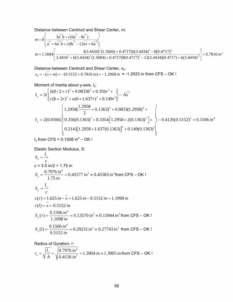
Distance between Centriod and Shear Center, m: 2 2 2
3 2 2 2
2 2 22
3 2 2 2
3 (6 8 )
6 (8 12 6
3(3.4434) (1.5684) 0.4717(6(3.4434) 8(0.4717)1.5684 0.78163.4434 6(3.4434) (1.5684) 0.4717(8(0.4717) 12(3.4434)(0.4717) 6(3.4434)
a b c a cm ba a b c c ac a
m in
⎡ ⎤+ −= ⎢ ⎥
⎢ ⎥+ + − +⎣ ⎦⎡ ⎤+ −
= =⎢ ⎥+ + − +⎣ ⎦ Distance between Centroid and Shear Center, xo:
0 ( ) (0.5152 0.7816 ) 1.2968x x m in in= − + = − + = − ≈ -1.2933 in from CFS – OK ! Moment of Inertia about y-axis, Iy:
[ ]
2 3 32
2 2 3
2 3
3 2
2
( / 2 ) 0.0833 0.3562
( 2 ) ( 1.637 ) 0.149
1.29581.2958( 0.1363) 0.0833(1.2958)2
2(0.0566) 0.356(0.1363) 0.3354 1.2958 2(0.1363)
0.2141 1.2958 1.637(0.1363) 0.
y
y
b b r b rI t Ax
c b r u b r r
I
⎧ ⎫+ + + +⎪ ⎪= −⎨ ⎬+ + + +⎪ ⎪⎩ ⎭
+ + +
⎡ ⎤= + + +⎣ ⎦
+ +
2 4
3
0.4126(0.5152) 0.1506
149(0.1363)
in
⎧ ⎫⎪ ⎪⎪ ⎪⎪ ⎪ − =⎨ ⎬⎪ ⎪⎪ ⎪⎪ ⎪⎩ ⎭
Iy from CFS = 0.1508 in4 – OK ! Elastic Section Modulus, S:
xx
ISc
=
c = 3.5 in/2 = 1.75 in 4
30.7976 0.45577 0.455831.75x
inS inin
= = ≈ 3in from CFS – OK !
yy
IS
c=
( ) 1.625 1.625 0.5152 1.1098c r in x in in in= − = − =
( ) 0.5152c l x in= = 4
30.1506( ) 0.13570 0.139441.1098y
inS r in inin
= = ≈ 3 from CFS – OK !
430.1506( ) 0.29231 0.27743
0.5152yinS l in inin
= = ≈ 3 from CFS – OK !
Radius of Gyration, r:
4
2
0.7976 1.3904 1.39050.4126
xx
I inr iA in
= = = ≈n in from CFS – OK !
58
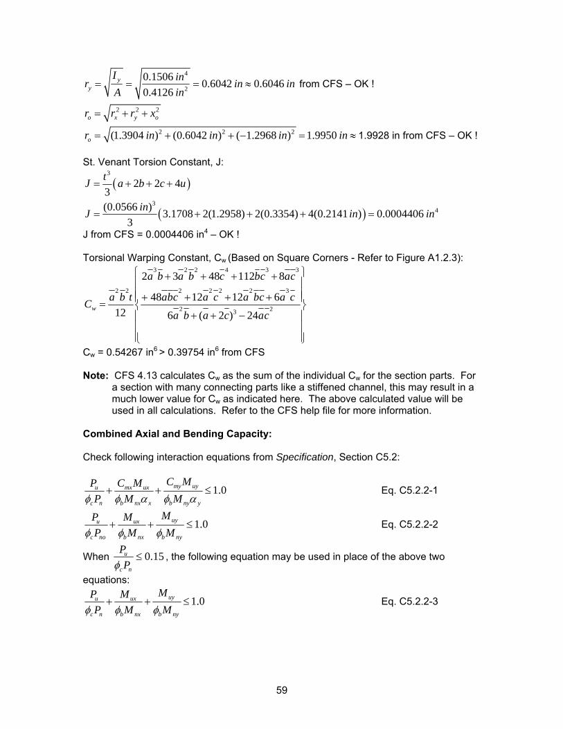
4
2
0.1506 0.6042 0.60460.4126
yy
I inr iA in
= = = ≈n in from CFS – OK !
2 2 2o x yr r r x= + + o
2 2 2(1.3904 ) (0.6042 ) ( 1.2968 ) 1.9950or in in in= + + − = in ≈ 1.9928 in from CFS – OK ! St. Venant Torsion Constant, J:
( )3
2 2 43tJ a b c u= + + +
( )3
4(0.0566 ) 3.1708 2(1.2958) 2(0.3354) 4(0.2141 ) 0.00044063
inJ i= + + + =n in
J from CFS = 0.0004406 in4 – OK ! Torsional Warping Constant, Cw (Based on Square Corners - Refer to Figure A1.2.3):
3 2 2 4 3 3
2 2 2 2 2 2 3
2 23
2 3 48 112 8
48 12 12 612 6 ( 2 ) 24
w
a b a b c bc ac
a b t abc a c a bc a cCa b a c ac
⎧ ⎫+ + + +⎪ ⎪⎪ ⎪+ + + +⎪ ⎪= ⎨ ⎬
+ + −⎪ ⎪⎪ ⎪⎪ ⎪⎩ ⎭
Cw = 0.54267 in6 > 0.39754 in6 from CFS Note: CFS 4.13 calculates Cw as the sum of the individual Cw for the section parts. For
a section with many connecting parts like a stiffened channel, this may result in a much lower value for Cw as indicated here. The above calculated value will be used in all calculations. Refer to the CFS help file for more information.
Combined Axial and Bending Capacity: Check following interaction equations from Specification, Section C5.2:
1.0my uyu mx ux
c n b nx x b ny y
C MP C MP M Mφ φ α φ α
+ + ≤ Eq. C5.2.2-1
1.0uyu ux
c no b nx b ny
MP MP M Mφ φ φ
+ + ≤ Eq. C5.2.2-2
When 0.15u
c n
PPφ
≤ , the following equation may be used in place of the above two
equations:
1.0uyu ux
c n b nx b ny
MP MP M Mφ φ φ
+ + ≤ Eq. C5.2.2-3
59
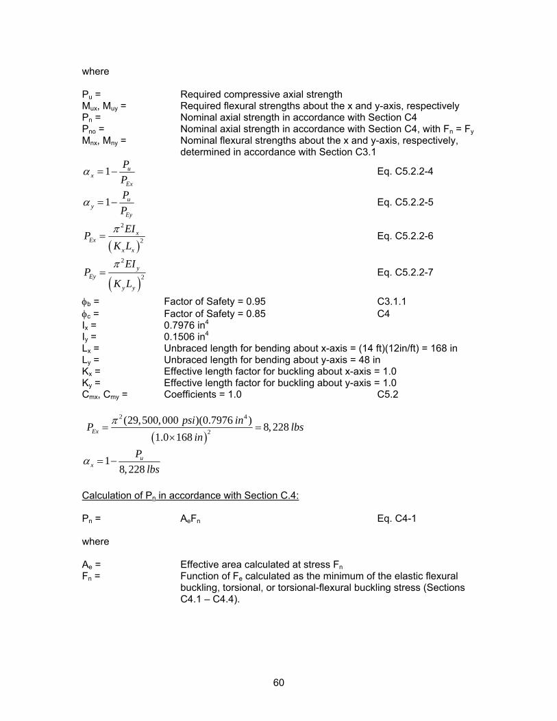
where Pu = Required compressive axial strength Mux, Muy = Required flexural strengths about the x and y-axis, respectively Pn = Nominal axial strength in accordance with Section C4 Pno = Nominal axial strength in accordance with Section C4, with Fn = FyMnx, Mny = Nominal flexural strengths about the x and y-axis, respectively,
determined in accordance with Section C3.1
1 ux
Ex
PP
α = − Eq. C5.2.2-4
1 uy
Ey
PP
α = − Eq. C5.2.2-5
( )
2
2x
Exx x
EIPK Lπ
= Eq. C5.2.2-6
( )2
2y
Ey
y y
EIP
K L
π= Eq. C5.2.2-7
φb = Factor of Safety = 0.95 C3.1.1 φc = Factor of Safety = 0.85 C4 Ix = 0.7976 in4
Iy = 0.1506 in4
Lx = Unbraced length for bending about x-axis = (14 ft)(12in/ft) = 168 in Ly = Unbraced length for bending about y-axis = 48 in Kx = Effective length factor for buckling about x-axis = 1.0 Ky = Effective length factor for buckling about y-axis = 1.0 Cmx, Cmy = Coefficients = 1.0 C5.2
( )
2 4
2(29,500,000 )(0.7976 ) 8,228
1.0 168Ex
psi inP lin
π= =
×bs
18,228
ux
Plbs
α = −
Calculation of Pn in accordance with Section C.4: Pn = AeFn Eq. C4-1 where Ae = Effective area calculated at stress FnFn = Function of Fe calculated as the minimum of the elastic flexural
buckling, torsional, or torsional-flexural buckling stress (Sections C4.1 – C4.4).
60
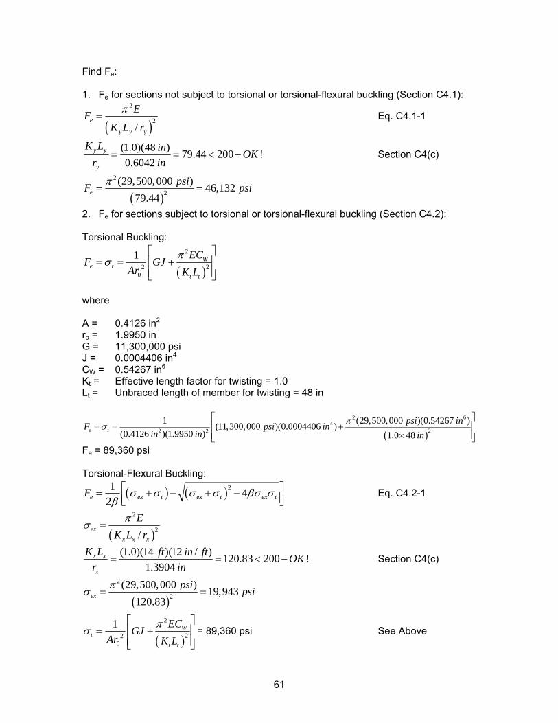
Find Fe: 1. Fe for sections not subject to torsional or torsional-flexural buckling (Section C4.1):
( )2
2/
e
y y y
EFK L r
π= Eq. C4.1-1
(1.0)(48 ) 79.44 200 !0.6042
y y
y
K L in OKr in
= = < − Section C4(c)
( )
2
2(29,500,000 ) 46,132
79.44e
psiF pπ= = si
2. Fe for sections subject to torsional or torsional-flexural buckling (Section C4.2): Torsional Buckling:
( )
2
220
1 We t
t t
ECF GJAr K L
πσ⎡ ⎤
= = +⎢ ⎥⎢ ⎥⎣ ⎦
where A = 0.4126 in2
ro = 1.9950 in G = 11,300,000 psi J = 0.0004406 in4 CW = 0.54267 in6 Kt = Effective length factor for twisting = 1.0 Lt = Unbraced length of member for twisting = 48 in
( )
2 64
22 2
1 (29,500,000 )(0.54267 )(11,300,000 )(0.0004406 )(0.4126 )(1.9950 ) 1.0 48
e tpsi inF psi in
in in inπσ
⎡ ⎤= = +⎢ ⎥
×⎢ ⎥⎣ ⎦Fe = 89,360 psi Torsional-Flexural Buckling:
( ) ( )21 42e ex t ex t eF x tσ σ σ σ βσ σ
β⎡= + − + −⎢⎣ ⎦
⎤⎥ Eq. C4.2-1
( )
2
2/ex
x x x
EK L r
πσ =
(1.0)(14 )(12 / ) 120.83 200 !1.3904
x x
x
K L ft in ft OKr in
= = < − Section C4(c)
( )
2
2(29,500,000 ) 19,943
120.83ex
psi psiπσ = =
( )
2
220
1 Wt
t t
ECGJAr K L
πσ⎡ ⎤
= +⎢⎢ ⎥⎣ ⎦
⎥ = 89,360 psi See Above
61
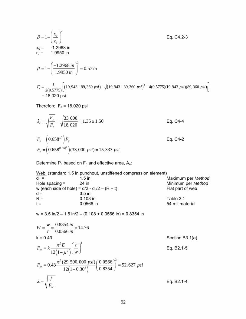
2
0
0
1 xr
β⎛ ⎞
= − ⎜ ⎟⎝ ⎠
Eq. C4.2-3
x0 = -1.2968 in r0 = 1.9950 in
21.29681 0.5775
1.9950in
inβ
⎛ ⎞−= − =⎜ ⎟
⎝ ⎠
( ) ( )21 19,943 89,360 19,943 89,360 4(0.5775)(19,943 )(89,360 )2(0.5775)eF psi psi psi psi⎡ ⎤= + − + −⎢ ⎥⎣ ⎦
= 18,020 psi Therefore, Fe = 18,020 psi
33,000 1.35 1.5018,020
yc
e
FF
λ = = = ≤ Eq. C4-4
( )2
0.658 cn yF Fλ= Eq. C4-2
( )2(1.35)0.658 (33,000 ) 15,333nF psi= = psi
Determine Pn based on Fn and effective area, Ae: Web: (standard 1.5 in punchout, unstiffened compression element) dh = 1.5 in Maximum per Method Hole spacing = 24 in Minimum per Method w (each side of hole) = d/2 - dh/2 – (R + t) Flat part of web d = 3.5 in R = 0.108 in Table 3.1 t = 0.0566 in 54 mil material w = 3.5 in/2 – 1.5 in/2 – (0.108 + 0.0566 in) = 0.8354 in
0.8354 14.760.0566
w inWt in
= = =
k = 0.43 Section B3.1(a)
( )22
212 1crE tF k
wπ
µ⎛ ⎞= ⎜ ⎟− ⎝ ⎠
Eq. B2.1-5
( )22
2
(29,500,000 ) 0.05660.43 52,6270.835412 1 0.30cr
psiF pπ ⎛ ⎞= =⎜ ⎟− ⎝ ⎠si
cr
fF
λ = Eq. B2.1-4
62
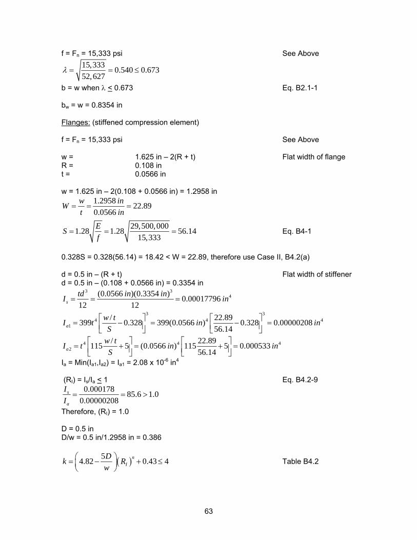
f = Fn = 15,333 psi See Above 15,333 0.540 0.67352,627
λ = = ≤
b = w when λ < 0.673 Eq. B2.1-1 bw = w = 0.8354 in Flanges: (stiffened compression element) f = Fn = 15,333 psi See Above w = 1.625 in – 2(R + t) Flat width of flange R = 0.108 in t = 0.0566 in w = 1.625 in – 2(0.108 + 0.0566 in) = 1.2958 in
1.2958 22.890.0566
w inWt in
= = =
29,500,0001.28 1.28 56.1415,333
ESf
= = = Eq. B4-1
0.328S = 0.328(56.14) = 18.42 < W = 22.89, therefore use Case II, B4.2(a) d = 0.5 in – (R + t) Flat width of stiffener d = 0.5 in – (0.108 + 0.0566 in) = 0.3354 in
3 34(0.0566 )(0.3354 ) 0.00017796
12 12std in inI in= = =
3 34 4
1/ 22.89399 0.328 399(0.0566 ) 0.328 0.00000208
56.14aw t 4I t inS
⎡ ⎤ ⎡ ⎤= − = − =⎢ ⎥ ⎢ ⎥⎣ ⎦ ⎣ ⎦in
4 42
/ 22.89115 5 (0.0566 ) 115 5 0.00053356.14a
w t 4I t inS
⎡ ⎤ ⎡ ⎤= + = + =⎢ ⎥ ⎢ ⎥⎣ ⎦ ⎣ ⎦in
Ia = Min(Ia1,Ia2) = Ia1 = 2.08 x 10⁻⁶ in4
(RI) = Is/Ia < 1 Eq. B4.2-9
0.000178 85.6 1.00.00000208
s
a
II
= = >
Therefore, (RI) = 1.0 D = 0.5 in D/w = 0.5 in/1.2958 in = 0.386
( )54.82 0.43 4nI
Dk Rw
⎛ ⎞= − + ≤⎜ ⎟⎝ ⎠
Table B4.2
63
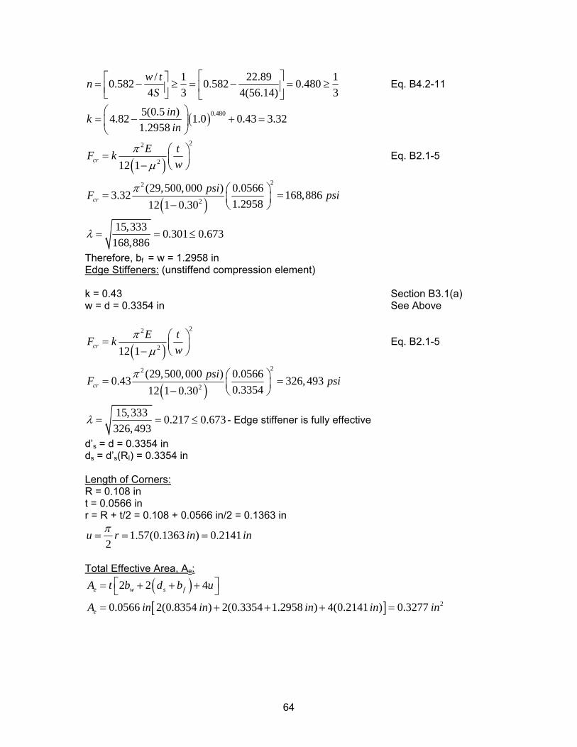
/ 1 22.89 10.582 0.582 0.4804 3 4(56.14) 3w tn
S⎡ ⎤⎡ ⎤= − ≥ = − =⎢ ⎥⎢ ⎥⎣ ⎦ ⎣ ⎦
≥ Eq. B4.2-11
( )0.4805(0.5 )4.82 1.0 0.43 3.321.2958
inkin
⎛ ⎞= − + =⎜ ⎟
⎝ ⎠
( )22
212 1crE tF k
wπ
µ⎛ ⎞= ⎜ ⎟− ⎝ ⎠
Eq. B2.1-5
( )22
2
(29,500,000 ) 0.05663.32 168,8861.295812 1 0.30cr
psiF pπ ⎛ ⎞= =⎜ ⎟− ⎝ ⎠si
15,333 0.301 0.673168,886
λ = = ≤
Therefore, bf = w = 1.2958 in Edge Stiffeners: (unstiffend compression element) k = 0.43 Section B3.1(a) w = d = 0.3354 in See Above
( )22
212 1crE tF k
wπ
µ⎛ ⎞= ⎜ ⎟− ⎝ ⎠
Eq. B2.1-5
( )22
2
(29,500,000 ) 0.05660.43 326,4930.335412 1 0.30cr
psiF pπ ⎛ ⎞= =⎜ ⎟− ⎝ ⎠si
15,333 0.217 0.673326,493
λ = = ≤ - Edge stiffener is fully effective
d’s = d = 0.3354 in ds = d’s(RI) = 0.3354 in Length of Corners: R = 0.108 in t = 0.0566 in r = R + t/2 = 0.108 + 0.0566 in/2 = 0.1363 in
1.57(0.1363 ) 0.21412
u r in inπ= = =
Total Effective Area, Ae:
( )[ ] 2
2 2 4
0.0566 2(0.8354 ) 2(0.3354 1.2958 ) 4(0.2141 ) 0.3277
e w s f
e
A t b d b u
A in in in in in
⎡ ⎤= + + +⎣ ⎦= + + + =
64
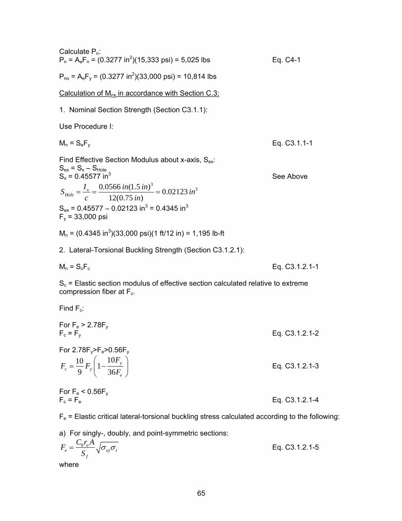
Calculate Pn: Pn = AeFn = (0.3277 in2)(15,333 psi) = 5,025 lbs Eq. C4-1 Pno = AeFy = (0.3277 in2)(33,000 psi) = 10,814 lbs Calculation of Mnx in accordance with Section C.3: 1. Nominal Section Strength (Section C3.1.1): Use Procedure I: Mn = SeFy Eq. C3.1.1-1 Find Effective Section Modulus about x-axis, Sex: Sex = Sx – SHole Sx = 0.45577 in3 See Above
330.0566 (1.5 ) 0.02123
12(0.75 )x
HoleI in inS ic in
= = = n
Sex = 0.45577 – 0.02123 in3 = 0.4345 in3
Fy = 33,000 psi Mn = (0.4345 in3)(33,000 psi)(1 ft/12 in) = 1,195 lb-ft 2. Lateral-Torsional Buckling Strength (Section C3.1.2.1): Mn = ScFc Eq. C3.1.2.1-1 Sc = Elastic section modulus of effective section calculated relative to extreme compression fiber at Fc. Find Fc: For Fe > 2.78FyFc = Fy Eq. C3.1.2.1-2 For 2.78Fy>Fe>0.56Fy
1010 19 36
yc y
e
FF F
F⎛ ⎞
= −⎜⎝ ⎠
⎟ Eq. C3.1.2.1-3
For Fe < 0.56FyFc = Fe Eq. C3.1.2.1-4 Fe = Elastic critical lateral-torsional buckling stress calculated according to the following: a) For singly-, doubly, and point-symmetric sections:
b oe
f
C r AFS ey tσ σ= Eq. C3.1.2.1-5
where
65
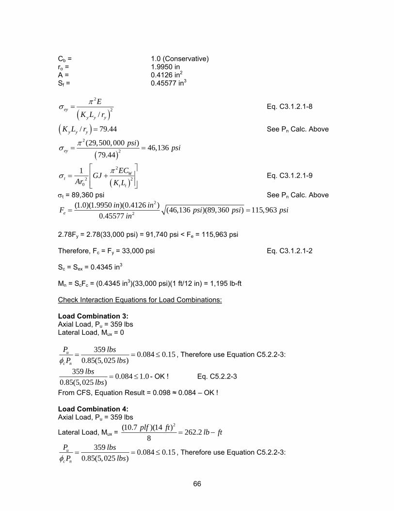
Cb = 1.0 (Conservative) ro = 1.9950 in A = 0.4126 in2
Sf = 0.45577 in3
( )2
2/
ey
y y y
E
K L r
πσ = Eq. C3.1.2.1-8
( )/ 79.44y y yK L r = See Pn Calc. Above
( )
2
2(29,500,000 ) 46,136
79.44ey
psi psiπσ = =
( )
2
220
1 Wt
t t
ECGJAr K L
πσ⎡ ⎤
= +⎢⎢ ⎥⎣ ⎦
⎥ Eq. C3.1.2.1-9
σt = 89,360 psi See Pn Calc. Above 2
2
(1.0)(1.9950 )(0.4126 ) (46,136 )(89,360 ) 115,9630.45577e
in inF psiin
= =psi psi
2.78Fy = 2.78(33,000 psi) = 91,740 psi < Fe = 115,963 psi Therefore, Fc = Fy = 33,000 psi Eq. C3.1.2.1-2 Sc = Sex = 0.4345 in3
Mn = ScFc = (0.4345 in3)(33,000 psi)(1 ft/12 in) = 1,195 lb-ft Check Interaction Equations for Load Combinations: Load Combination 3: Axial Load, Pu = 359 lbs Lateral Load, Mux = 0
359 0.084 0.150.85(5,025 )
u
c n
P lbsP lbsφ
= = ≤ , Therefore use Equation C5.2.2-3:
359 0.084 1.00.85(5,025 )
lbslbs
= ≤ - OK ! Eq. C5.2.2-3
From CFS, Equation Result = 0.098 ≈ 0.084 – OK ! Load Combination 4: Axial Load, Pu = 359 lbs
Lateral Load, Mux = 2(10.7 )(14 ) 262.2
8plf ft lb ft= −
359 0.084 0.150.85(5,025 )
u
c n
P lbsP lbsφ
= = ≤ , Therefore use Equation C5.2.2-3:
66
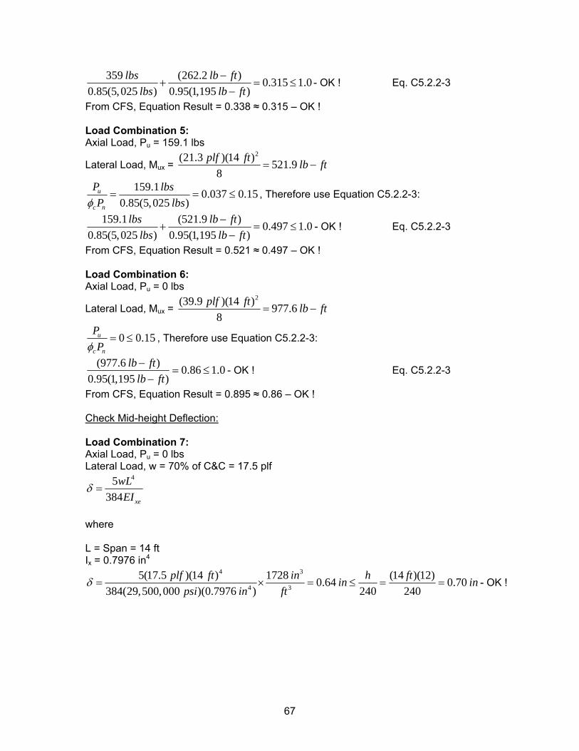
359 (262.2 ) 0.315 1.00.85(5,025 ) 0.95(1,195 )
lbs lb ftlbs lb ft
−+ =
−≤ - OK ! Eq. C5.2.2-3
From CFS, Equation Result = 0.338 ≈ 0.315 – OK ! Load Combination 5: Axial Load, Pu = 159.1 lbs
Lateral Load, Mux = 2(21.3 )(14 ) 521.9
8plf ft lb ft= −
159.1 0.037 0.150.85(5,025 )
u
c n
P lbsP lbsφ
= = ≤ , Therefore use Equation C5.2.2-3:
159.1 (521.9 ) 0.497 1.00.85(5,025 ) 0.95(1,195 )
lbs lb ftlbs lb ft
−+ =
−≤ - OK ! Eq. C5.2.2-3
From CFS, Equation Result = 0.521 ≈ 0.497 – OK ! Load Combination 6: Axial Load, Pu = 0 lbs
Lateral Load, Mux = 2(39.9 )(14 ) 977.6
8plf ft lb ft= −
0 0.15u
c n
PPφ
= ≤ , Therefore use Equation C5.2.2-3:
(977.6 ) 0.86 1.00.95(1,195 )
lb ftlb ft−
= ≤−
- OK ! Eq. C5.2.2-3
From CFS, Equation Result = 0.895 ≈ 0.86 – OK ! Check Mid-height Deflection: Load Combination 7: Axial Load, Pu = 0 lbs Lateral Load, w = 70% of C&C = 17.5 plf
45384 xe
wLEI
δ =
where L = Span = 14 ft Ix = 0.7976 in4
4 3
4 3
5(17.5 )(14 ) 1728 (14 )(12)0.64 0.70384(29,500,000 )(0.7976 ) 240 240
plf ft in h ftin inpsi in ft
δ = × = ≤ = = - OK !
67
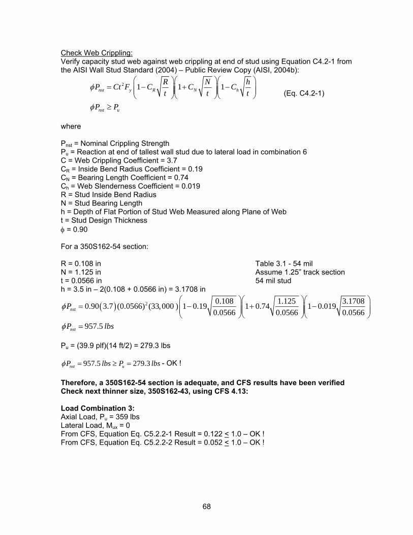
Check Web Crippling: Verify capacity stud web against web crippling at end of stud using Equation C4.2-1 from the AISI Wall Stud Standard (2004) – Public Review Copy (AISI, 2004b):
2 1 1 1nst y R N h
nst u
R N hP Ct F C C Ct t
P P
φ
φ
⎛ ⎞⎛ ⎞⎛= − + −⎜ ⎟⎜ ⎟⎜⎜ ⎟⎜ ⎟⎜
⎝ ⎠⎝ ⎠⎝≥
t⎞⎟⎟⎠ (Eq. C4.2-1)
where Pnst = Nominal Crippling Strength Pu = Reaction at end of tallest wall stud due to lateral load in combination 6 C = Web Crippling Coefficient = 3.7 CR = Inside Bend Radius Coefficient = 0.19 CN = Bearing Length Coefficient = 0.74 Ch = Web Slenderness Coefficient = 0.019 R = Stud Inside Bend Radius N = Stud Bearing Length h = Depth of Flat Portion of Stud Web Measured along Plane of Web t = Stud Design Thickness φ = 0.90 For a 350S162-54 section: R = 0.108 in Table 3.1 - 54 mil N = 1.125 in Assume 1.25” track section t = 0.0566 in 54 mil stud h = 3.5 in – 2(0.108 + 0.0566 in) = 3.1708 in
( ) 2 0.108 1.125 3.17080.90 3.7 (0.0566) (33,000 ) 1 0.19 1 0.74 1 0.0190.0566 0.0566 0.0566
957.5
nst
nst
P
P lbs
φ
φ
⎛ ⎞⎛ ⎞⎛= − + −⎜ ⎟⎜ ⎟⎜⎜ ⎟⎜ ⎟⎜
⎝ ⎠⎝ ⎠⎝=
⎞⎟⎟⎠
Pu = (39.9 plf)(14 ft/2) = 279.3 lbs
957.5 279.3nst uP lbs P lbsφ = ≥ = - OK ! Therefore, a 350S162-54 section is adequate, and CFS results have been verified Check next thinner size, 350S162-43, using CFS 4.13: Load Combination 3: Axial Load, Pu = 359 lbs Lateral Load, Mux = 0 From CFS, Equation Eq. C5.2.2-1 Result = 0.122 < 1.0 – OK ! From CFS, Equation Eq. C5.2.2-2 Result = 0.052 < 1.0 – OK !
68
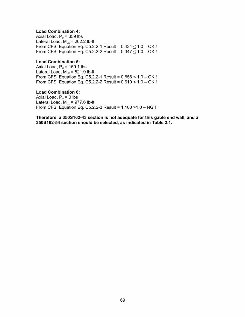
Load Combination 4: Axial Load, Pu = 359 lbs Lateral Load, Mux = 262.2 lb-ft From CFS, Equation Eq. C5.2.2-1 Result = 0.434 < 1.0 – OK ! From CFS, Equation Eq. C5.2.2-2 Result = 0.347 < 1.0 – OK ! Load Combination 5: Axial Load, Pu = 159.1 lbs Lateral Load, Mux = 521.9 lb-ft From CFS, Equation Eq. C5.2.2-1 Result = 0.656 < 1.0 – OK ! From CFS, Equation Eq. C5.2.2-2 Result = 0.610 < 1.0 – OK ! Load Combination 6: Axial Load, Pu = 0 lbs Lateral Load, Mux = 977.6 lb-ft From CFS, Equation Eq. C5.2.2-3 Result = 1.100 >1.0 – NG ! Therefore, a 350S162-43 section is not adequate for this gable end wall, and a 350S162-54 section should be selected, as indicated in Table 2.1.
69
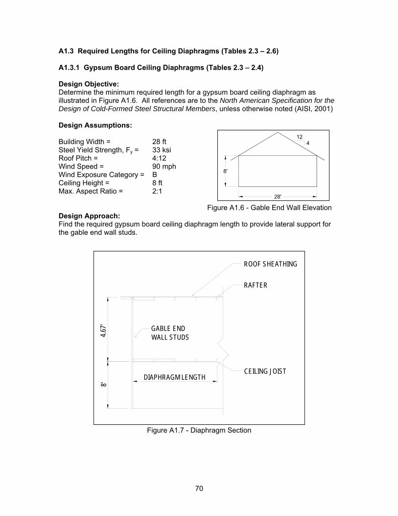
A1.3 Required Lengths for Ceiling Diaphragms (Tables 2.3 – 2.6) A1.3.1 Gypsum Board Ceiling Diaphragms (Tables 2.3 – 2.4) Design Objective: Determine the minimum required length for a gypsum board ceiling diaphragm as illustrated in Figure A1.6. All references are to the North American Specification for the Design of Cold-Formed Steel Structural Members, unless otherwise noted (AISI, 2001) Design Assumptions: Building Width = 28 ft Steel Yield Strength, Fy = 33 ksi Roof Pitch = 4:12 Wind Speed = 90 mph
12
28'
8'
4
Wind Exposure Category = B Ceiling Height = 8 ft Max. Aspect Ratio = 2:1 Figure A1.6 - Gable End Wall Elevation Design Approach: Find the required gypsum board ceiling diaphragm length to provide lateral support for the gable end wall studs.
RAFTER
ROOF SHEATHING
GABLE ENDWALL STUDS
CEILING JOISTDIAPHRAGM LENGTH
4.67'
8'
Figure A1.7 - Diaphragm Section
70
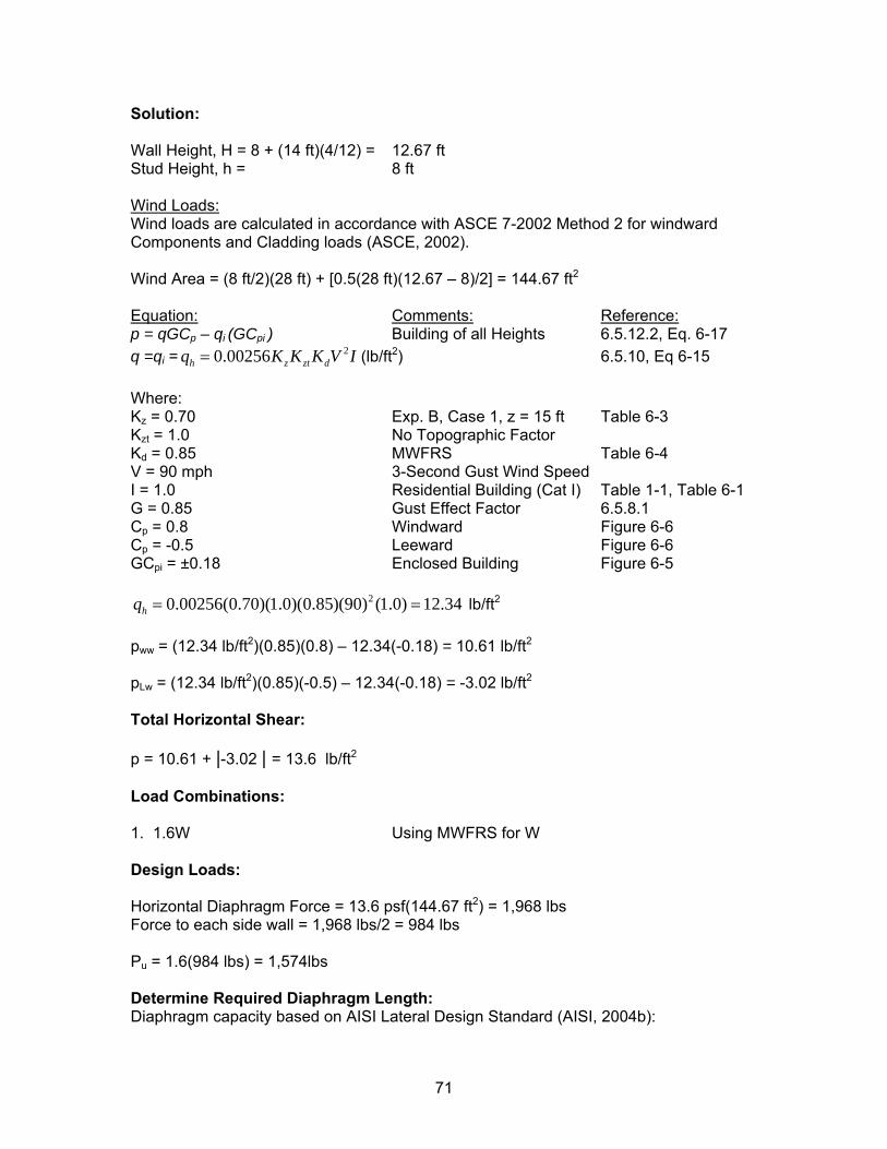
Solution: Wall Height, H = 8 + (14 ft)(4/12) = 12.67 ft Stud Height, h = 8 ft Wind Loads: Wind loads are calculated in accordance with ASCE 7-2002 Method 2 for windward Components and Cladding loads (ASCE, 2002). Wind Area = (8 ft/2)(28 ft) + [0.5(28 ft)(12.67 – 8)/2] = 144.67 ft2
Equation: Comments: Reference: p = qGCp – qi (GCpi ) Building of all Heights 6.5.12.2, Eq. 6-17 q =qi = (lb/ft20.00256h z ztq K K K= dV I 2) 6.5.10, Eq 6-15 Where: Kz = 0.70 Exp. B, Case 1, z = 15 ft Table 6-3 Kzt = 1.0 No Topographic Factor Kd = 0.85 MWFRS Table 6-4 V = 90 mph 3-Second Gust Wind Speed I = 1.0 Residential Building (Cat I) Table 1-1, Table 6-1 G = 0.85 Gust Effect Factor 6.5.8.1 Cp = 0.8 Windward Figure 6-6 Cp = -0.5 Leeward Figure 6-6 GCpi = ±0.18 Enclosed Building Figure 6-5
20.00256(0.70)(1.0)(0.85)(90) (1.0) 12.34hq = = lb/ft2
pww = (12.34 lb/ft2)(0.85)(0.8) – 12.34(-0.18) = 10.61 lb/ft2
pLw = (12.34 lb/ft2)(0.85)(-0.5) – 12.34(-0.18) = -3.02 lb/ft2 Total Horizontal Shear: p = 10.61 + |-3.02 | = 13.6 lb/ft2 Load Combinations: 1. 1.6W Using MWFRS for W Design Loads: Horizontal Diaphragm Force = 13.6 psf(144.67 ft2) = 1,968 lbs Force to each side wall = 1,968 lbs/2 = 984 lbs Pu = 1.6(984 lbs) = 1,574lbs Determine Required Diaphragm Length: Diaphragm capacity based on AISI Lateral Design Standard (AISI, 2004b):
71
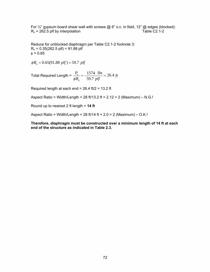
For ½” gypsum board shear wall with screws @ 6” o.c. in field, 12” @ edges (blocked): Rn = 262.5 plf by interpolation Table C2.1-2 Reduce for unblocked diaphragm per Table C2.1-2 footnote 3: Rn = 0.35(262.5 plf) = 91.88 plf φ = 0.65
0.65(91.88 ) 59.7nR plf plfφ = =
Total Required Length = 1,556.7 26.1
59.7u
n
P lbs ftR plfφ
= = 1574 26.4
Required length at each end = 26.4 ft/2 = 13.2 ft Aspect Ratio = Width/Length = 28 ft/13.2 ft = 2.12 > 2 (Maximum) – N.G.! Round up to nearest 2 ft length = 14 ft Aspect Ratio = Width/Length = 28 ft/14 ft = 2.0 = 2 (Maximum) – O.K.! Therefore, diaphragm must be constructed over a minimum length of 14 ft at each end of the structure as indicated in Table 2.3.
72
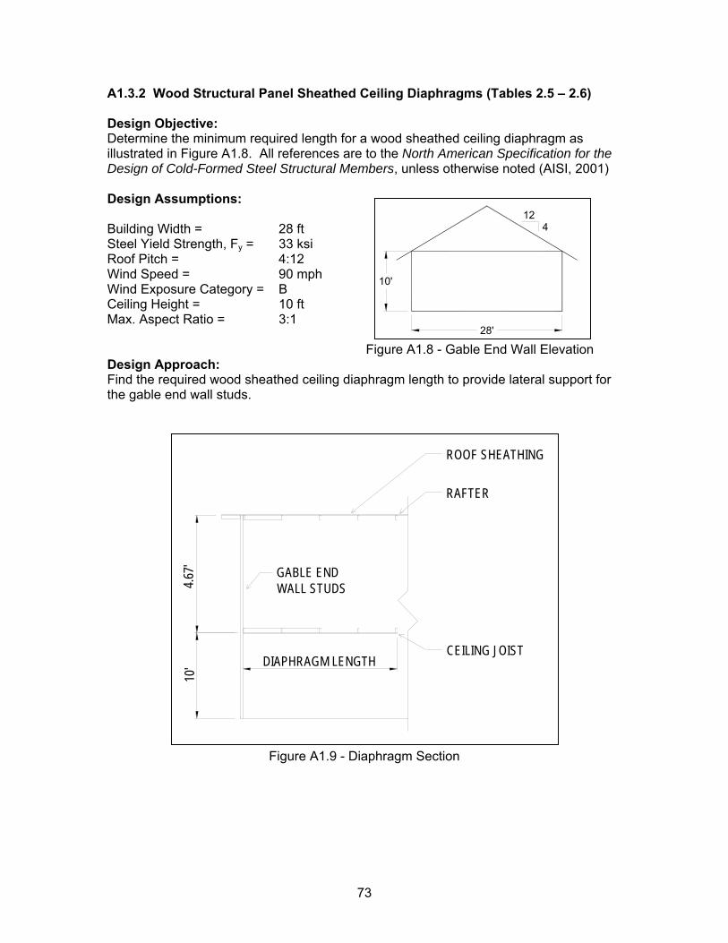
A1.3.2 Wood Structural Panel Sheathed Ceiling Diaphragms (Tables 2.5 – 2.6) Design Objective: Determine the minimum required length for a wood sheathed ceiling diaphragm as illustrated in Figure A1.8. All references are to the North American Specification for the Design of Cold-Formed Steel Structural Members, unless otherwise noted (AISI, 2001) Design Assumptions: Building Width = 28 ft Steel Yield Strength, Fy = 33 ksi Roof Pitch = 4:12 Wind Speed = 90 mph Wind Exposure Category = B Ceiling Height = 10 ft Max. Aspect Ratio = 3:1
124
28'
10'
Figure A1.8 - Gable End Wall Elevation Design Approach: Find the required wood sheathed ceiling diaphragm length to provide lateral support for the gable end wall studs.
RAFTER
ROOF SHEATHING
GABLE ENDWALL STUDS
CEILING JOISTDIAPHRAGM LENGTH
4.67'
10'
Figure A1.9 - Diaphragm Section
73
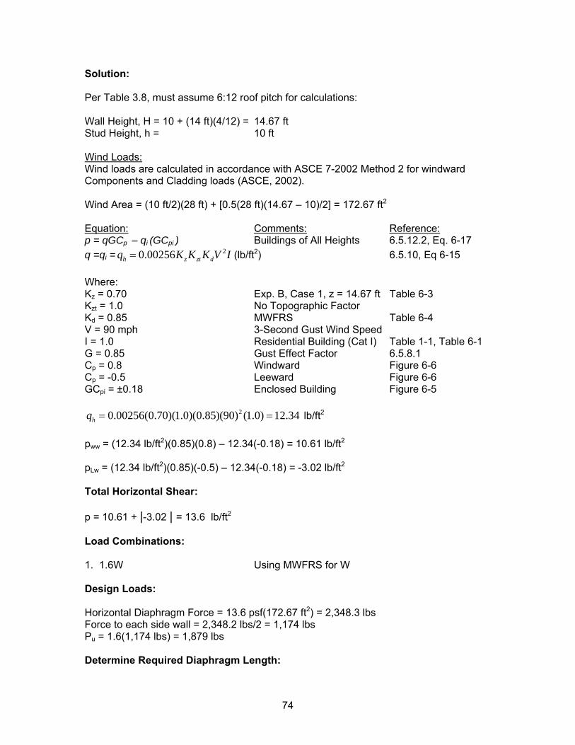
Solution: Per Table 3.8, must assume 6:12 roof pitch for calculations: Wall Height, H = 10 + (14 ft)(4/12) = 14.67 ft Stud Height, h = 10 ft Wind Loads: Wind loads are calculated in accordance with ASCE 7-2002 Method 2 for windward Components and Cladding loads (ASCE, 2002). Wind Area = (10 ft/2)(28 ft) + [0.5(28 ft)(14.67 – 10)/2] = 172.67 ft2
Equation: Comments: Reference: p = qGCp – qi (GCpi ) Buildings of All Heights 6.5.12.2, Eq. 6-17 q =qi = (lb/ft20.00256h z ztq K K K= dV I 2) 6.5.10, Eq 6-15 Where: Kz = 0.70 Exp. B, Case 1, z = 14.67 ft Table 6-3 Kzt = 1.0 No Topographic Factor Kd = 0.85 MWFRS Table 6-4 V = 90 mph 3-Second Gust Wind Speed I = 1.0 Residential Building (Cat I) Table 1-1, Table 6-1 G = 0.85 Gust Effect Factor 6.5.8.1 Cp = 0.8 Windward Figure 6-6 Cp = -0.5 Leeward Figure 6-6 GCpi = ±0.18 Enclosed Building Figure 6-5
20.00256(0.70)(1.0)(0.85)(90) (1.0) 12.34hq = = lb/ft2
pww = (12.34 lb/ft2)(0.85)(0.8) – 12.34(-0.18) = 10.61 lb/ft2 pLw = (12.34 lb/ft2)(0.85)(-0.5) – 12.34(-0.18) = -3.02 lb/ft2 Total Horizontal Shear: p = 10.61 + |-3.02 | = 13.6 lb/ft2 Load Combinations: 1. 1.6W Using MWFRS for W Design Loads: Horizontal Diaphragm Force = 13.6 psf(172.67 ft2) = 2,348.3 lbs Force to each side wall = 2,348.2 lbs/2 = 1,174 lbs Pu = 1.6(1,174 lbs) = 1,879 lbs Determine Required Diaphragm Length:
74
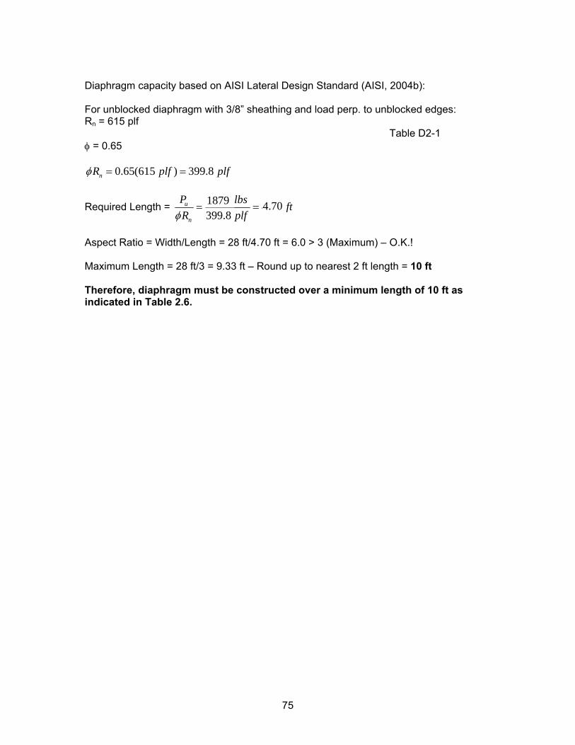
Diaphragm capacity based on AISI Lateral Design Standard (AISI, 2004b): For unblocked diaphragm with 3/8” sheathing and load perp. to unblocked edges: Rn = 615 plf Table D2-1 φ = 0.65
0.65(615 ) 399.8nR plf plfφ = =
Required Length = 1,837 4.59399.8
u
n
P lbs ftR plfφ
= = 1879 4.70
Aspect Ratio = Width/Length = 28 ft/4.70 ft = 6.0 > 3 (Maximum) – O.K.! Maximum Length = 28 ft/3 = 9.33 ft – Round up to nearest 2 ft length = 10 ft Therefore, diaphragm must be constructed over a minimum length of 10 ft as indicated in Table 2.6.
75
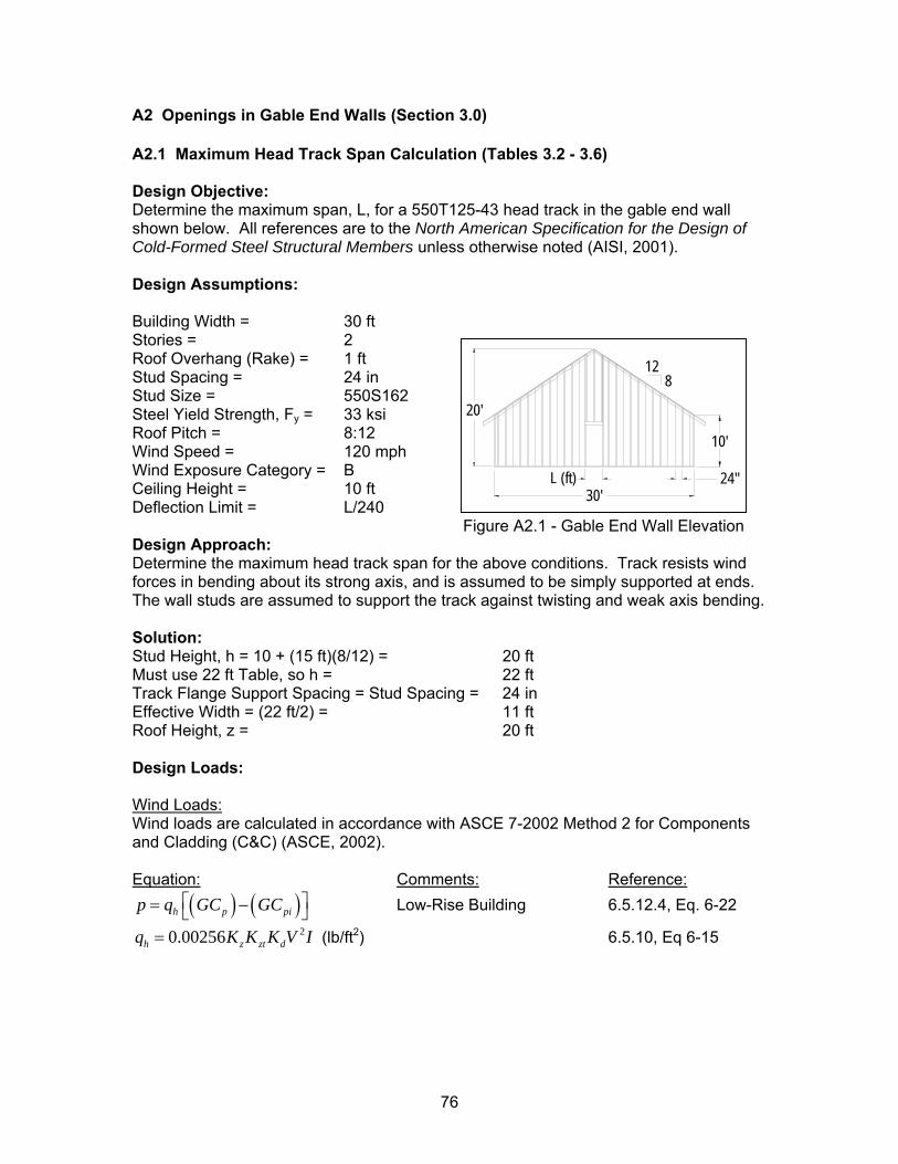
A2 Openings in Gable End Walls (Section 3.0) A2.1 Maximum Head Track Span Calculation (Tables 3.2 - 3.6) Design Objective: Determine the maximum span, L, for a 550T125-43 head track in the gable end wall shown below. All references are to the North American Specification for the Design of Cold-Formed Steel Structural Members unless otherwise noted (AISI, 2001). Design Assumptions: Building Width = 30 ft Stories = 2
20'
30'24"
812
L (ft)
10'
Roof Overhang (Rake) = 1 ft Stud Spacing = 24 in Stud Size = 550S162 Steel Yield Strength, Fy = 33 ksi Roof Pitch = 8:12 Wind Speed = 120 mph Wind Exposure Category = B Ceiling Height = 10 ft Deflection Limit = L/240 Figure A2.1 - Gable End Wall Elevation Design Approach: Determine the maximum head track span for the above conditions. Track resists wind forces in bending about its strong axis, and is assumed to be simply supported at ends. The wall studs are assumed to support the track against twisting and weak axis bending. Solution: Stud Height, h = 10 + (15 ft)(8/12) = 20 ft Must use 22 ft Table, so h = 22 ft Track Flange Support Spacing = Stud Spacing = 24 in Effective Width = (22 ft/2) = 11 ftRoof Height, z = 20 ft Design Loads: Wind Loads: Wind loads are calculated in accordance with ASCE 7-2002 Method 2 for Components and Cladding (C&C) (ASCE, 2002). Equation: Comments: Reference:
( ) ( )h p pip q GC GC⎡ ⎤= −⎣ ⎦
dV I
Low-Rise Building 6.5.12.4, Eq. 6-22 20.00256h z ztq K K K= (lb/ft2) 6.5.10, Eq 6-15
76
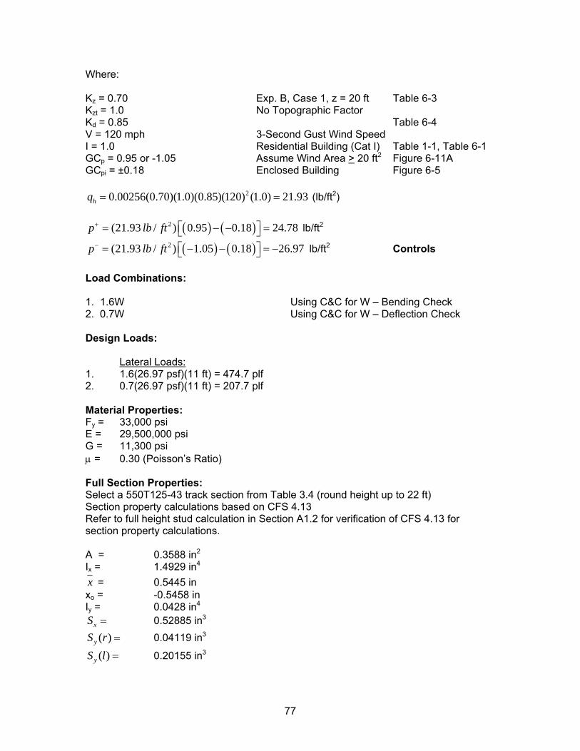
Where: Kz = 0.70 Exp. B, Case 1, z = 20 ft Table 6-3 Kzt = 1.0 No Topographic Factor Kd = 0.85 Table 6-4 V = 120 mph 3-Second Gust Wind Speed I = 1.0 Residential Building (Cat I) Table 1-1, Table 6-1 GCp = 0.95 or -1.05 Assume Wind Area > 20 ft2 Figure 6-11A GCpi = ±0.18 Enclosed Building Figure 6-5
20.00256(0.70)(1.0)(0.85)(120) (1.0) 21.93hq = =
=
−
(lb/ft2)
( ) ( )2(21.93 / ) 0.95 0.18 24.78p lb ft+ ⎡ ⎤= − −⎣ ⎦ lb/ft2
( ) ( )2(21.93 / ) 1.05 0.18 26.97p lb ft− ⎡ ⎤= − − =⎣ ⎦ lb/ft2 Controls Load Combinations: 1. 1.6W Using C&C for W – Bending Check 2. 0.7W Using C&C for W – Deflection Check Design Loads:
Lateral Loads: 1. 1.6(26.97 psf)(11 ft) = 474.7 plf 2. 0.7(26.97 psf)(11 ft) = 207.7 plf Material Properties: Fy = 33,000 psi E = 29,500,000 psi G = 11,300 psi µ = 0.30 (Poisson’s Ratio) Full Section Properties: Select a 550T125-43 track section from Table 3.4 (round height up to 22 ft) Section property calculations based on CFS 4.13 Refer to full height stud calculation in Section A1.2 for verification of CFS 4.13 for section property calculations. A = 0.3588 in2
Ix = 1.4929 in4
x = 0.5445 in xo = -0.5458 in Iy = 0.0428 in4
xS = 0.52885 in3
( )yS r = 0.04119 in3
( )yS l = 0.20155 in3
77
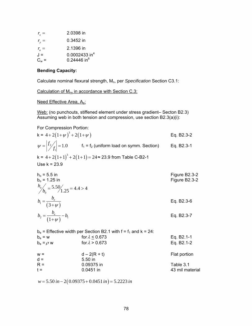
xr = 2.0398 in
yr = 0.3452 in
or = 2.1396 in J = 0.0002433 in4
Cw = 0.24446 in6 Bending Capacity: Calculate nominal flexural strength, Mn, per Specification Section C3.1: Calculation of Mnx in accordance with Section C.3: Need Effective Area, Ae: Web: (no punchouts, stiffened element under stress gradient– Secton B2.3) Assuming web in both tension and compression, use section B2.3(a)(i): For Compression Portion: k = ( ) (34 2 1 2 1 )ψ ψ+ + + + Eq. B2.3-2
2
11.0f
fψ = = f1 = f2 (uniform load on symm. Section) Eq. B2.3-1
k = ( ) ( )34 2 1 1 2 1 1 24+ + + + = ≈ 23.9 from Table C-B2-1 Use k = 23.9 ho = 5.5 in Figure B2.3-2 bo = 1.25 in Figure B2.3-2
0
5.50 4.4 41.25oh
b = = >
( )1 3ebbψ
=+
Eq. B2.3-6
( )2 1ebbψ
=+ 1b− Eq. B2.3-7
be = Effective width per Section B2.1 with f = f1 and k = 24: be = w for λ < 0.673 Eq. B2.1-1 be = ρ w for λ > 0.673 Eq. B2.1-2 w = d – 2(R + t) Flat portion d = 5.50 in R = 0.09375 in Table 3.1 t = 0.0451 in 43 mil material
( )5.50 2 0.09375 0.0451 5.2223w in in= − + = in
78
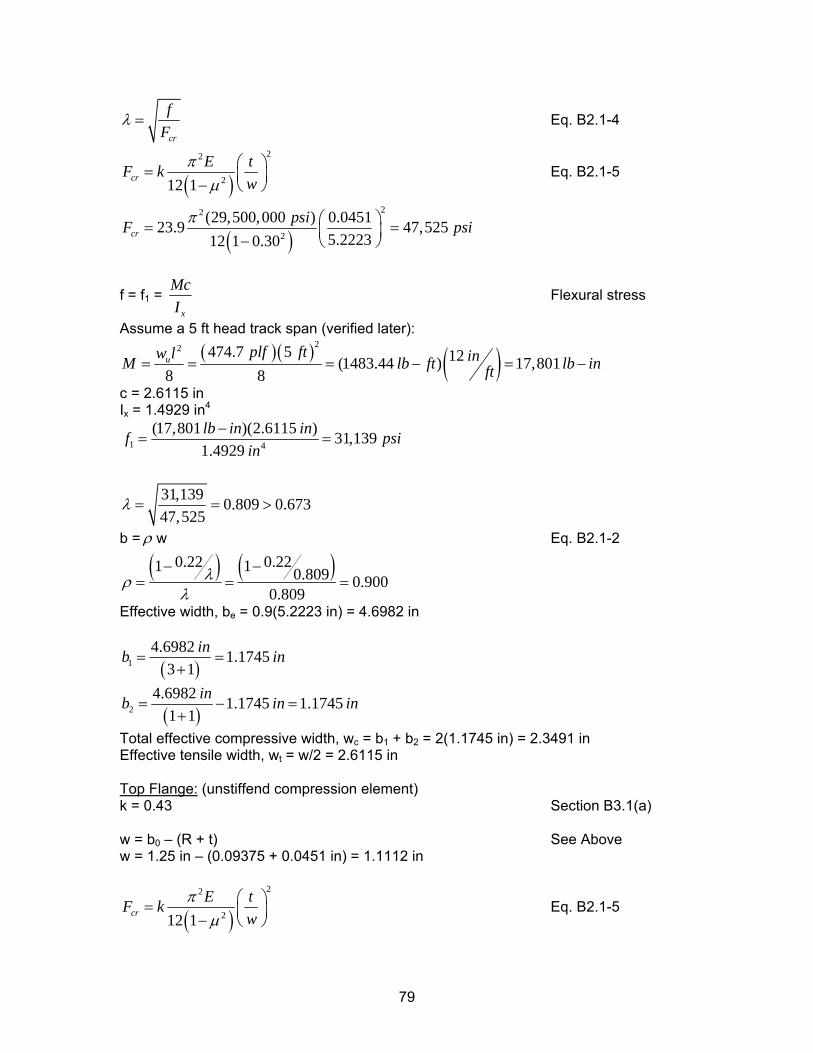
cr
fF
λ = Eq. B2.1-4
( )22
212 1crE tF k
wπ
µ⎛ ⎞= ⎜ ⎟− ⎝ ⎠
Eq. B2.1-5
( )22
2
(29,500,000 ) 0.045123.9 47,5255.222312 1 0.30cr
psiF pπ ⎛ ⎞= =⎜ ⎟− ⎝ ⎠si
f = f1 = x
McI
Flexural stress
Assume a 5 ft head track span (verified later):
( )( ) ( )22 474.7 5 12(1483.44 ) 17,801
8 8u plf ftw l inM lb ft lb inft= = = − = −
c = 2.6115 in Ix = 1.4929 in4
1 4
(17,801 )(2.6115 ) 31,1391.4929lb in inf psi
in−
= =
31,139 0.809 0.67347,525
λ = = >
b = ρ w Eq. B2.1-2
( ) ( )0.22 0.221 1 0.809 0.9000.809
λρλ
− −= = =
Effective width, be = 0.9(5.2223 in) = 4.6982 in
( )14.6982 1.1745
3 1inb i= =
+n
( )24.6982 1.1745 1.1745
1 1inb in= − =
+in
Total effective compressive width, wc = b1 + b2 = 2(1.1745 in) = 2.3491 in Effective tensile width, wt = w/2 = 2.6115 in Top Flange: (unstiffend compression element) k = 0.43 Section B3.1(a) w = b0 – (R + t) See Above w = 1.25 in – (0.09375 + 0.0451 in) = 1.1112 in
( )22
212 1crE tF k
wπ
µ⎛ ⎞= ⎜ ⎟− ⎝ ⎠
Eq. B2.1-5
79
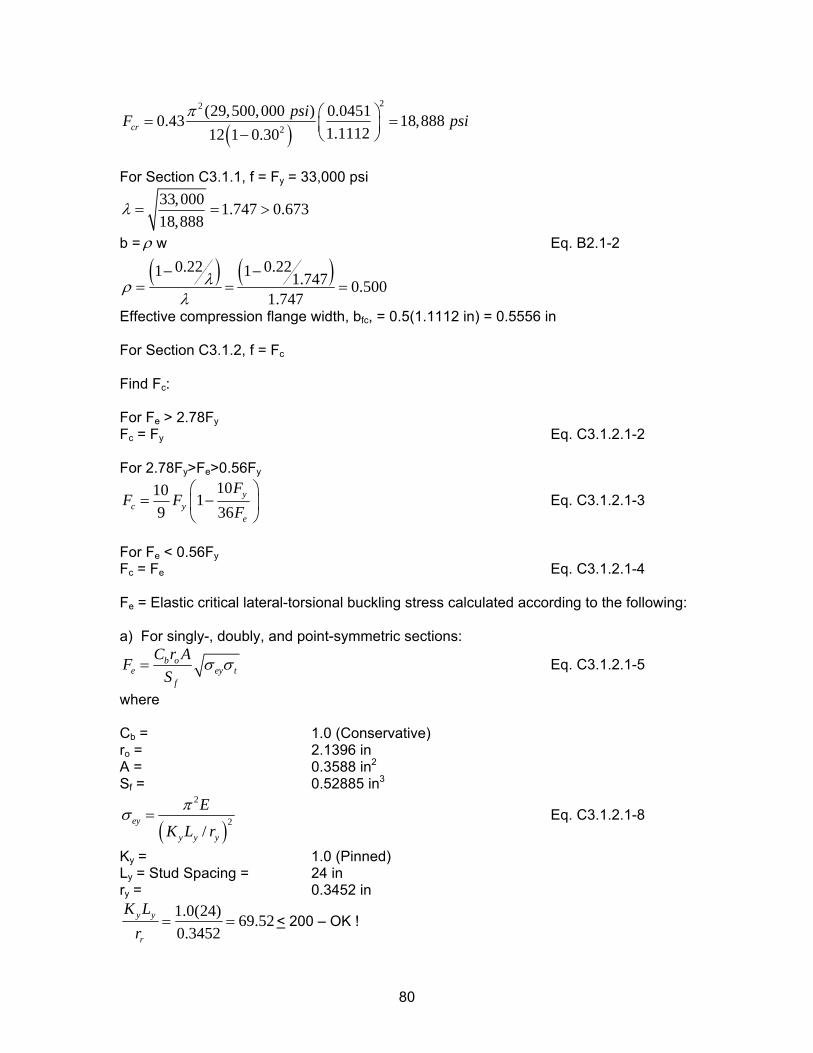
( )22
2
(29,500,000 ) 0.04510.43 18,8881.111212 1 0.30cr
psiF pπ ⎛ ⎞= =⎜ ⎟− ⎝ ⎠si
For Section C3.1.1, f = Fy = 33,000 psi
33,000 1.747 0.67318,888
λ = = >
b = ρ w Eq. B2.1-2
( ) ( )0.22 0.221 1 1.747 0.5001.747
λρλ
− −= = =
Effective compression flange width, bfc, = 0.5(1.1112 in) = 0.5556 in For Section C3.1.2, f = Fc Find Fc: For Fe > 2.78FyFc = Fy Eq. C3.1.2.1-2 For 2.78Fy>Fe>0.56Fy
1010 19 36
yc y
e
FF F
F⎛ ⎞
= −⎜⎝ ⎠
⎟ Eq. C3.1.2.1-3
For Fe < 0.56FyFc = Fe Eq. C3.1.2.1-4 Fe = Elastic critical lateral-torsional buckling stress calculated according to the following: a) For singly-, doubly, and point-symmetric sections:
b oe
f
C r AFS ey tσ σ= Eq. C3.1.2.1-5
where Cb = 1.0 (Conservative) ro = 2.1396 in A = 0.3588 in2
Sf = 0.52885 in3
( )2
2/
ey
y y y
E
K L r
πσ = Eq. C3.1.2.1-8
Ky = 1.0 (Pinned) Ly = Stud Spacing = 24 in ry = 0.3452 in
1.0(24) 69.520.3452
y y
r
K Lr
= = < 200 – OK !
80
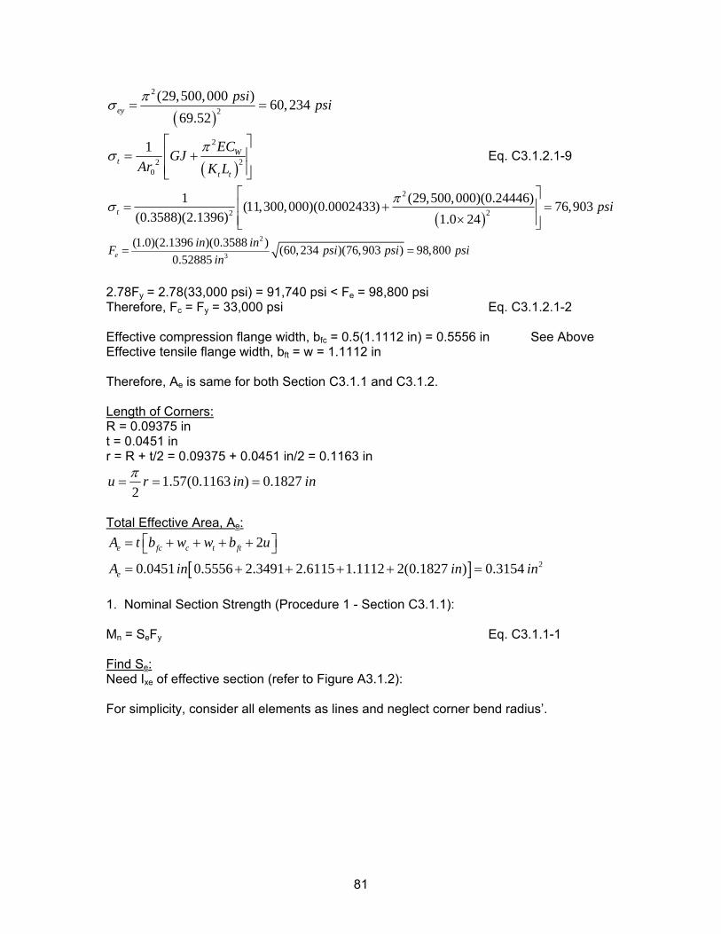
( )
2
2(29,500,000 ) 60,234
69.52ey
psi psiπσ = =
( )
2
220
1 Wt
t t
ECGJAr K L
πσ⎡ ⎤
= +⎢⎢ ⎥⎣ ⎦
⎥ Eq. C3.1.2.1-9
( )
2
22
1 (29,500,000)(0.24446)(11,300,000)(0.0002433) 76,903(0.3588)(2.1396) 1.0 24
t psiπσ⎡ ⎤
= +⎢ ⎥×⎢ ⎥⎣ ⎦
=
2
3
(1.0)(2.1396 )(0.3588 ) (60,234 )(76,903 ) 98,8000.52885e
in inF psi psi psiin
= =
2.78Fy = 2.78(33,000 psi) = 91,740 psi < Fe = 98,800 psi Therefore, Fc = Fy = 33,000 psi Eq. C3.1.2.1-2 Effective compression flange width, bfc = 0.5(1.1112 in) = 0.5556 in See Above Effective tensile flange width, bft = w = 1.1112 in Therefore, Ae is same for both Section C3.1.1 and C3.1.2. Length of Corners: R = 0.09375 in t = 0.0451 in r = R + t/2 = 0.09375 + 0.0451 in/2 = 0.1163 in
1.57(0.1163 ) 0.18272
u r in inπ= = =
Total Effective Area, Ae:
[ ] 2
2
0.0451 0.5556 2.3491 2.6115 1.1112 2(0.1827 ) 0.3154e fc c t ft
e
A t b w w b u
A in in in
⎡ ⎤= + + + +⎣ ⎦= + + + + =
1. Nominal Section Strength (Procedure 1 - Section C3.1.1): Mn = SeFy Eq. C3.1.1-1 Find Se: Need Ixe of effective section (refer to Figure A3.1.2): For simplicity, consider all elements as lines and neglect corner bend radius’.
81
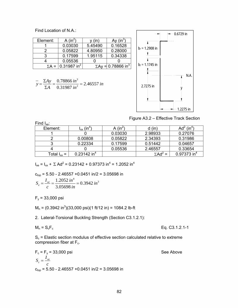
Find Location of N.A.:
3
2
0.78866 2.465570.31987
Ay iny iA in
Σ= = =
Σn
Figure A3.2 – Effective Track Section Find Ixe:
Ixe = Ixx + AdΣ 2 = 0.23142 + 0.97373 in4 = 1.2052 in4
ctop = 5.50 - 2.46557 +0.0451 in/2 = 3.05698 in
431.2052 0.3942
3.05698xe
eI inS ic in
= = = n
Fy = 33,000 psi Mn = (0.3942 in3)(33,000 psi)(1 ft/12 in) = 1084.2 lb-ft 2. Lateral-Torsional Buckling Strength (Section C3.1.2.1): Mn = ScFc Eq. C3.1.2.1-1 Sc = Elastic section modulus of effective section calculated relative to extreme compression fiber at Fc. Fc = Fy = 33,000 psi See Above
xec
ISc
=
ctop = 5.50 - 2.46557 +0.0451 in/2 = 3.05698 in
Element: A (in2) y (in) Ay (in3) 1 0.03030 5.45490 0.16528 2 0.05822 4.80950 0.28000 3 0.17599 1.95115 0.34338 4 0.05536 0 0
ΣA = 0.31987 in2 ΣAy = 0.78866 in3
Element: Ixx (in4) A (in2) d (in) Ad2 (in4) 1 0 0.03030 2.98933 0.27076 2 0.00808 0.05822 2.34393 0.31986 3 0.22334 0.17599 0.51442 0.04657 4 0 0.05536 2.46557 0.33654
Total Ixx = 0.23142 in4 ΣAd2 = 0.97373 in4
1.2275 in
2.7275 in
2 = 1.1745 in
y
N.A.
0.6729 in
b
b1 = 1.2908 in
82
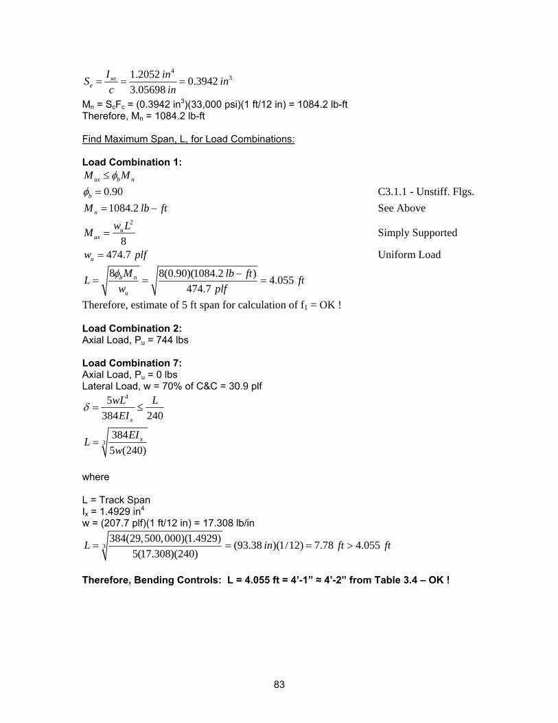
431.2052 0.3942
3.05698xe
eI inS ic in
= = = n
Mn = ScFc = (0.3942 in3)(33,000 psi)(1 ft/12 in) = 1084.2 lb-ft Therefore, Mn = 1084.2 lb-ft Find Maximum Span, L, for Load Combinations: Load Combination 1:
ux b nM Mφ≤ 0.90bφ = C3.1.1 - Unstiff. Flgs. 1084.2nM lb ft= − See Above
2
8u
uxw LM = Simply Supported
474.7uw = plf Uniform Load
8 8(0.90)(1084.2 ) 4.055474.7
b n
u
M lb ftL fw plf
φ −= = = t
Therefore, estimate of 5 ft span for calculation of f1 = OK ! Load Combination 2: Axial Load, Pu = 744 lbs Load Combination 7: Axial Load, Pu = 0 lbs Lateral Load, w = 70% of C&C = 30.9 plf
4
3
5384 240
3845 (240)
x
x
wL LEI
EILw
δ = ≤
=
where L = Track Span Ix = 1.4929 in4
w = (207.7 plf)(1 ft/12 in) = 17.308 lb/in
3384(29,500,000)(1.4929) (93.38 )(1/12) 7.78 4.055
5(17.308)(240)L in= = = ft ft>
Therefore, Bending Controls: L = 4.055 ft = 4’-1” ≈ 4’-2” from Table 3.4 – OK !
83
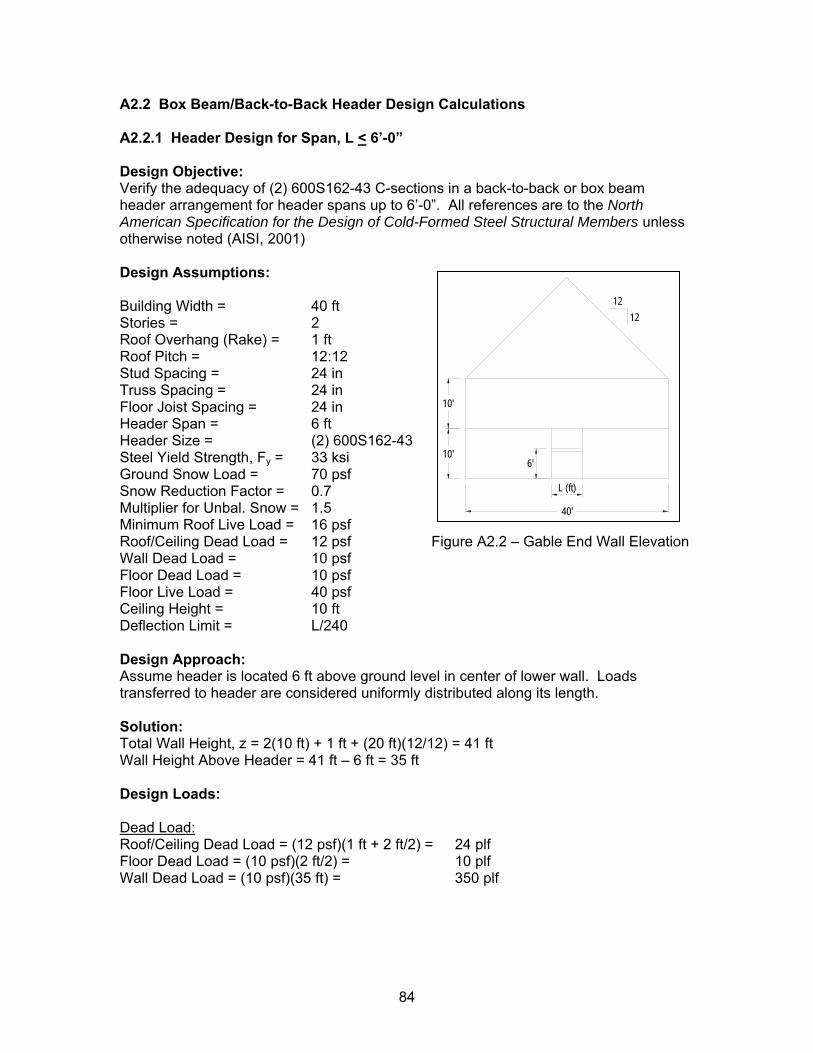
A2.2 Box Beam/Back-to-Back Header Design Calculations A2.2.1 Header Design for Span, L < 6’-0” Design Objective: Verify the adequacy of (2) 600S162-43 C-sections in a back-to-back or box beam header arrangement for header spans up to 6’-0”. All references are to the North American Specification for the Design of Cold-Formed Steel Structural Members unless otherwise noted (AISI, 2001) Design Assumptions: Building Width = 40 ft Stories = 2 Roof Overhang (Rake) = 1 ft Roof Pitch = 12:12 Stud Spacing = 24 in Truss Spacing = 24 in Floor Joist Spacing = 24 in Header Span = 6 ft Header Size = (2) 600S162-43 Steel Yield Strength, Fy = 33 ksi Ground Snow Load = 70 psf Snow Reduction Factor = 0.7 Multiplier for Unbal. Snow = 1.5 Minimum Roof Live Load = 16 psf Roof/Ceiling Dead Load = 12 psf Figure A2.2 – Gable End Wall Elevation Wall Dead Load = 10 psf Floor Dead Load = 10 psf Floor Live Load = 40 psf Ceiling Height = 10 ft Deflection Limit = L/240
40'
10'
10'6'
1212
L (ft)
Design Approach: Assume header is located 6 ft above ground level in center of lower wall. Loads transferred to header are considered uniformly distributed along its length. Solution: Total Wall Height, z = 2(10 ft) + 1 ft + (20 ft)(12/12) = 41 ft Wall Height Above Header = 41 ft – 6 ft = 35 ft Design Loads: Dead Load: Roof/Ceiling Dead Load = (12 psf)(1 ft + 2 ft/2) = 24 plf Floor Dead Load = (10 psf)(2 ft/2) = 10 plf Wall Dead Load = (10 psf)(35 ft) = 350 plf
84
Live Loads: Roof Live Load = (16 psf)(1 ft + 2 ft/2) = 32 plf Roof Snow Load = (0.7x70 psf x 1.5)(1 ft + 2 ft/2) = 147 plf Therefore, roof snow loads control over roof live loads. Floor Live Load = (40 psf)(2 ft/2) = 40 plf Load Combinations: 1. 1.4D 2. 1.2D + 1.6L + 0.5(Lr or S) 3. 1.2D + 0.5 L + 1.6(Lr or S) Design Loads:
1. 1.4(24 + 10 + 350 plf) = 537.6 plf 2. 1.2(24 + 10 + 350 plf) + 1.6(40 plf) + 0.5(147 plf) = 598.3 plf 3. 1.2(24 + 10 + 350 plf) + 0.5(40 plf) + 1.6(147 plf) = 716 plf Controlling Load Combination: 3. 716 plf Maximum Moment, Mux =
( )2(716 )(6 ) 12 13222 38.66
8 1000plf ft in kiplb ft k in
ft lbs⎛ ⎞⎛ ⎞
= − =⎜ ⎟⎜ ⎟⎝ ⎠⎝ ⎠
−
Check Adequacy of (2) 600S162-43 with CFS 4.13: Consider compression flange continuously supported by track section: Lb = 0
nx uM Mφ ≥ From CFS, 52.77 38.66nxM k in k inφ = − ≥ − - OK ! Check Web Crippling @ Stud Location: Design Loads: From above, wu = 716 plf Stud Spacing = 2 ft Stud Axial Load Pu = (716 plf)(2 ft) = 1432 lbs Determine Web Crippling Strength per Section C3.4:
2 sin 1 1 1n y R N hR N hP Ct F C C Ct t
θ⎛ ⎞⎛ ⎞⎛
= − + −⎜ ⎟⎜ ⎟⎜⎜ ⎟⎜ ⎟⎜⎝ ⎠⎝ ⎠⎝ t
⎞⎟⎟⎠
Eq. C3.4.1-1
For Back-to-Back Headers Fastened to Support with Interior Load (Table C3.4.1-1): t = 0.0451 in 43 mil web R = 0.09375 in Table 3.1 N = 1.125 in 1.25 in track h = 6 in – 2(0.09375 + 0.0451 in) = 5.7223 in Flat part of web Fy = 33,000 psi 33 ksi steel
85
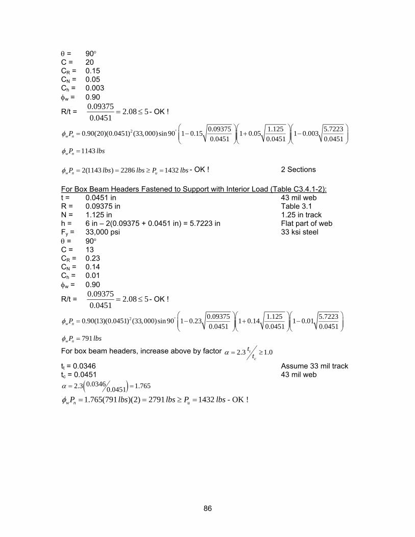
θ = 90° C = 20 CR = 0.15 CN = 0.05 Ch = 0.003 φw = 0.90
R/t = 0.09375 2.08 50.0451
= ≤ - OK !
2 0.09375 1.125 5.72230.90(20)(0.0451) (33,000)sin 90 1 0.15 1 0.05 1 0.0030.0451 0.0451 0.0451
1143
w n
w n
P
P lbs
φ
φ
° ⎛ ⎞⎛ ⎞⎛= − +⎜ ⎟⎜ ⎟⎜⎜ ⎟⎜ ⎟⎜
⎝ ⎠⎝ ⎠⎝=
⎞− ⎟⎟
⎠
2(1143 ) 2286 1432w n uP lbs lbs P lbsφ = = ≥ = - OK ! 2 Sections
For Box Beam Headers Fastened to Support with Interior Load (Table C3.4.1-2): t = 0.0451 in 43 mil web R = 0.09375 in Table 3.1 N = 1.125 in 1.25 in track h = 6 in – 2(0.09375 + 0.0451 in) = 5.7223 in Flat part of web Fy = 33,000 psi 33 ksi steel θ = 90° C = 13 CR = 0.23 CN = 0.14 Ch = 0.01 φw = 0.90
R/t = 0.09375 2.08 50.0451
= ≤ - OK !
2 0.09375 1.125 5.72230.90(13)(0.0451) (33,000)sin 90 1 0.23 1 0.14 1 0.010.0451 0.0451 0.0451
791
w n
w n
P
P lbs
φ
φ
° ⎛ ⎞⎛ ⎞⎛= − +⎜ ⎟⎜ ⎟⎜⎜ ⎟⎜ ⎟⎜
⎝ ⎠⎝ ⎠⎝=
⎞− ⎟⎟
⎠
For box beam headers, increase above by factor 2.3 1.0t
c
ttα = ≥
tt = 0.0346 Assume 33 mil track tc = 0.0451 43 mil web
( )0.03462.3 1.7650.0451α = =
1.765(791 )(2) 2791 1432w n uP lbs lbs P lbsφ = = ≥ = - OK !
86
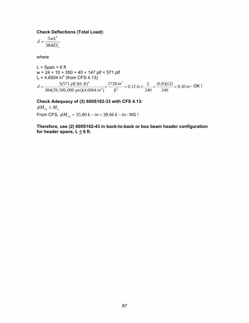
Check Deflections (Total Load): 45
384 x
wLEI
δ =
where L = Span = 6 ft w = 24 + 10 + 350 + 40 + 147 plf = 571 plf Ix = 4.6004 in4 (from CFS 4.13)
4 3
4 3
5(571 )(6 ) 1728 (6 )(12)0.12 0.30384(29,500,000 )(4.6004 ) 240 240
plf ft in L ftin inpsi in ft
δ = × = ≤ = = - OK !
Check Adequacy of (2) 600S162-33 with CFS 4.13:
nx uM Mφ ≥ From CFS, 35.80 38.66nxM k in k inφ = − < − - NG ! Therefore, use (2) 600S162-43 in back-to-back or box beam header configuration for header spans, L < 6 ft.
87
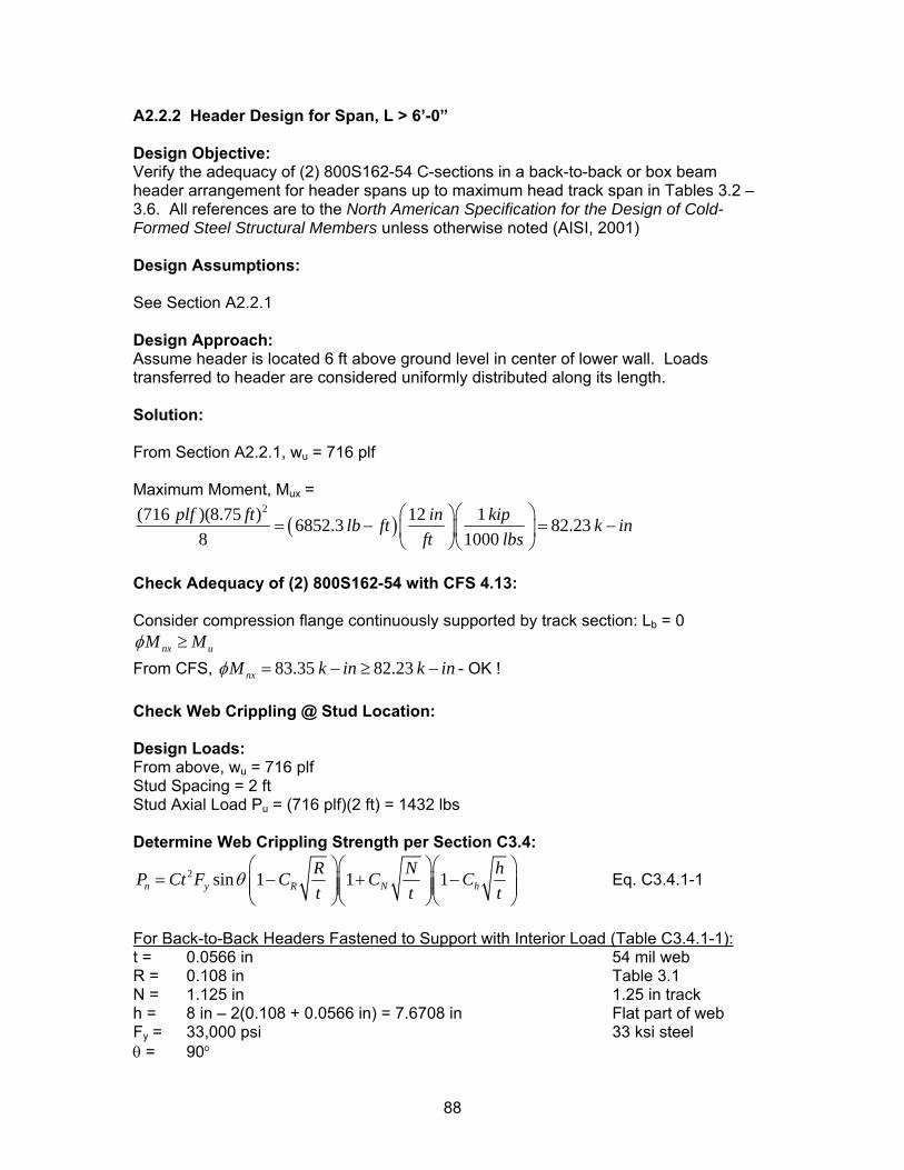
A2.2.2 Header Design for Span, L > 6’-0” Design Objective: Verify the adequacy of (2) 800S162-54 C-sections in a back-to-back or box beam header arrangement for header spans up to maximum head track span in Tables 3.2 – 3.6. All references are to the North American Specification for the Design of Cold-Formed Steel Structural Members unless otherwise noted (AISI, 2001) Design Assumptions: See Section A2.2.1 Design Approach: Assume header is located 6 ft above ground level in center of lower wall. Loads transferred to header are considered uniformly distributed along its length. Solution: From Section A2.2.1, wu = 716 plf Maximum Moment, Mux =
( )2(716 )(8.75 ) 12 16852.3 82.23
8 1000plf ft in kiplb ft k in
ft lbs⎛ ⎞⎛ ⎞
= − =⎜ ⎟⎜ ⎟⎝ ⎠⎝ ⎠
−
Check Adequacy of (2) 800S162-54 with CFS 4.13: Consider compression flange continuously supported by track section: Lb = 0
nx uM Mφ ≥ From CFS, 83.35 82.23nxM k in k inφ = − ≥ − - OK ! Check Web Crippling @ Stud Location: Design Loads: From above, wu = 716 plf Stud Spacing = 2 ft Stud Axial Load Pu = (716 plf)(2 ft) = 1432 lbs Determine Web Crippling Strength per Section C3.4:
2 sin 1 1 1n y R N hR N hP Ct F C C Ct t
θ⎛ ⎞⎛ ⎞⎛
= − + −⎜ ⎟⎜ ⎟⎜⎜ ⎟⎜ ⎟⎜⎝ ⎠⎝ ⎠⎝ t
⎞⎟⎟⎠
Eq. C3.4.1-1
For Back-to-Back Headers Fastened to Support with Interior Load (Table C3.4.1-1): t = 0.0566 in 54 mil web R = 0.108 in Table 3.1 N = 1.125 in 1.25 in track h = 8 in – 2(0.108 + 0.0566 in) = 7.6708 in Flat part of web Fy = 33,000 psi 33 ksi steel θ = 90°
88
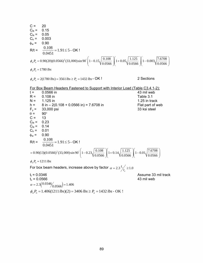
C = 20 CR = 0.15 CN = 0.05 Ch = 0.003 φw = 0.90
R/t = 0.108 1.91 50.0451
= ≤ - OK !
2 0.108 1.125 7.67080.90(20)(0.0566) (33,000)sin 90 1 0.15 1 0.05 1 0.0030.0566 0.0566 0.0566
1780
w n
w n
P
P lbs
φ
φ
° ⎛ ⎞⎛ ⎞⎛= − +⎜ ⎟⎜ ⎟⎜⎜ ⎟⎜ ⎟⎜
⎝ ⎠⎝ ⎠⎝=
⎞− ⎟⎟
⎠
2(1780 ) 3561 1432w n uP lbs lbs P lbsφ = = ≥ = - OK ! 2 Sections
For Box Beam Headers Fastened to Support with Interior Load (Table C3.4.1-2): t = 0.0566 in 43 mil web R = 0.108 in Table 3.1 N = 1.125 in 1.25 in track h = 8 in – 2(0.108 + 0.0566 in) = 7.6708 in Flat part of web Fy = 33,000 psi 33 ksi steel θ = 90° C = 13 CR = 0.23 CN = 0.14 Ch = 0.01 φw = 0.90
R/t = 0.108 1.91 50.0451
= ≤ - OK !
2 0.108 1.125 7.67080.90(13)(0.0566) (33,000)sin 90 1 0.23 1 0.14 1 0.010.0566 0.0566 0.0566
1211w nP lbsφ
° ⎛ ⎞⎛ ⎞⎛= − +⎜ ⎟⎜ ⎟⎜⎜ ⎟⎜ ⎟⎜
⎝ ⎠⎝ ⎠⎝=
⎞− ⎟⎟
⎠
For box beam headers, increase above by factor 2.3 1.0t
c
ttα = ≥
tt = 0.0346 Assume 33 mil track tc = 0.0566 43 mil web
( )0.03462.3 1.4060.0566α = =
1.406(1211 )(2) 3406 1432w n uP lbs lbs P lbsφ = = ≥ = - OK !
89
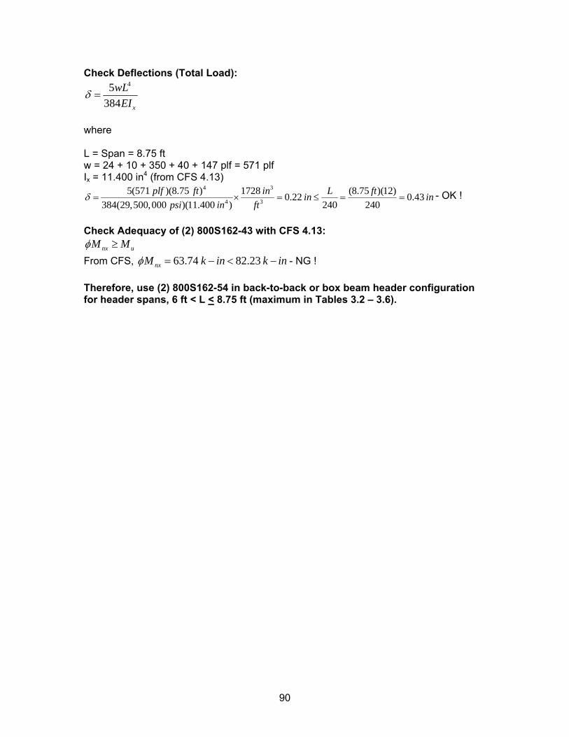
Check Deflections (Total Load): 45
384 x
wLEI
δ =
where L = Span = 8.75 ft w = 24 + 10 + 350 + 40 + 147 plf = 571 plf Ix = 11.400 in4 (from CFS 4.13)
4 3
4 3
5(571 )(8.75 ) 1728 (8.75 )(12)0.22 0.43384(29,500,000 )(11.400 ) 240 240
plf ft in L ftin inpsi in ft
δ = × = ≤ = = - OK !
Check Adequacy of (2) 800S162-43 with CFS 4.13:
nx uM Mφ ≥ From CFS, 63.74 82.23nxM k in k inφ = − < − - NG ! Therefore, use (2) 800S162-54 in back-to-back or box beam header configuration for header spans, 6 ft < L < 8.75 ft (maximum in Tables 3.2 – 3.6).
90
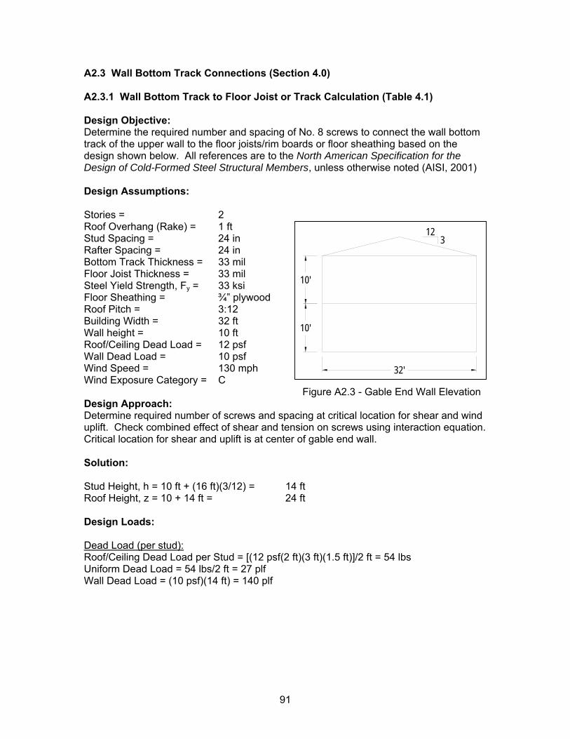
A2.3 Wall Bottom Track Connections (Section 4.0) A2.3.1 Wall Bottom Track to Floor Joist or Track Calculation (Table 4.1) Design Objective: Determine the required number and spacing of No. 8 screws to connect the wall bottom track of the upper wall to the floor joists/rim boards or floor sheathing based on the design shown below. All references are to the North American Specification for the Design of Cold-Formed Steel Structural Members, unless otherwise noted (AISI, 2001) Design Assumptions: Stories = 2 Roof Overhang (Rake) = 1 ft Stud Spacing = 24 in Rafter Spacing = 24 in Bottom Track Thickness = 33 mil Floor Joist Thickness = 33 mil Steel Yield Strength, Fy = 33 ksi Floor Sheathing = ¾” plywood Roof Pitch = 3:12 Building Width = 32 ft Wall height = 10 ft Roof/Ceiling Dead Load = 12 psf Wall Dead Load = 10 psf Wind Speed = 130 mph Wind Exposure Category = C
Figure A2.3 - Gable End Wall Elevation
32'
10'
10'
123
Design Approach: Determine required number of screws and spacing at critical location for shear and wind uplift. Check combined effect of shear and tension on screws using interaction equation. Critical location for shear and uplift is at center of gable end wall. Solution: Stud Height, h = 10 ft + (16 ft)(3/12) = 14 ft Roof Height, z = 10 + 14 ft = 24 ft Design Loads: Dead Load (per stud): Roof/Ceiling Dead Load per Stud = [(12 psf(2 ft)(3 ft)(1.5 ft)]/2 ft = 54 lbs Uniform Dead Load = 54 lbs/2 ft = 27 plf Wall Dead Load = (10 psf)(14 ft) = 140 plf
91
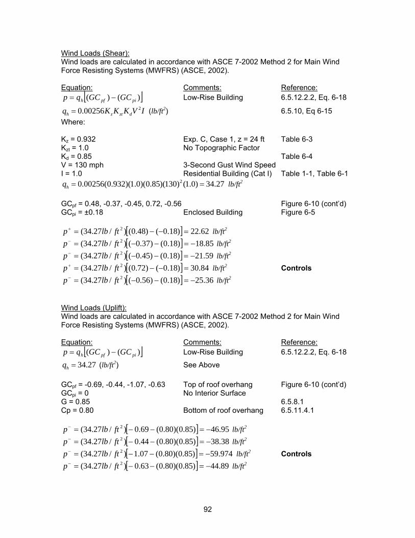
Wind Loads (Shear): Wind loads are calculated in accordance with ASCE 7-2002 Method 2 for Main Wind Force Resisting Systems (MWFRS) (ASCE, 2002). Equation: Comments: Reference:
[ ])()( pipfh GCGCqp −=
dV I
Low-Rise Building 6.5.12.2.2, Eq. 6-18 20.00256h z ztq K K K= (lb/ft2) 6.5.10, Eq 6-15
Where: Kz = 0.932 Exp. C, Case 1, z = 24 ft Table 6-3 Kzt = 1.0 No Topographic Factor Kd = 0.85 Table 6-4 V = 130 mph 3-Second Gust Wind Speed I = 1.0 Residential Building (Cat I) Table 1-1, Table 6-1
20.00256(0.932)(1.0)(0.85)(130) (1.0) 34.27hq = = lb/ft2
GCpf = 0.48, -0.37, -0.45, 0.72, -0.56 Figure 6-10 (cont’d) GCpi = ±0.18 Enclosed Building Figure 6-5
[ ] 62.22)18.0()48.0()/27.34( 2 =−−=+ ftlbp lb/ft2 [ ] 85.18)18.0()37.0()/27.34( 2 −=−−=− ftlbp lb/ft2
[ ] 59.21)18.0()45.0()/27.34( 2 −=−−=− ftlbp lb/ft2
[ ] 84.30)18.0()72.0()/27.34( 2 =−−=+ ftlbp lb/ft2 Controls [ ] 36.25)18.0()56.0()/27.34( 2 −=−−=− ftlbp lb/ft2
Wind Loads (Uplift): Wind loads are calculated in accordance with ASCE 7-2002 Method 2 for Main Wind Force Resisting Systems (MWFRS) (ASCE, 2002). Equation: Comments: Reference:
[ ])()( pipfh GCGCqp −= Low-Rise Building 6.5.12.2.2, Eq. 6-18
34.27hq = (lb/ft2) See Above GCpf = -0.69, -0.44, -1.07, -0.63 Top of roof overhang Figure 6-10 (cont’d) GCpi = 0 No Interior Surface G = 0.85 6.5.8.1 Cp = 0.80 Bottom of roof overhang 6.5.11.4.1
[ ] 95.46)85.0)(80.0(69.0)/27.34( 2 −=−−=− ftlbp lb/ft2
[ ] 38.38)85.0)(80.0(44.0)/27.34( 2 −=−−=− ftlbp lb/ft2
[ ] 974.59)85.0)(80.0(07.1)/27.34( 2 −=−−=− ftlbp lb/ft2 Controls [ ] 89.44)85.0)(80.0(63.0)/27.34( 2 −=−−=− ftlbp lb/ft2
92
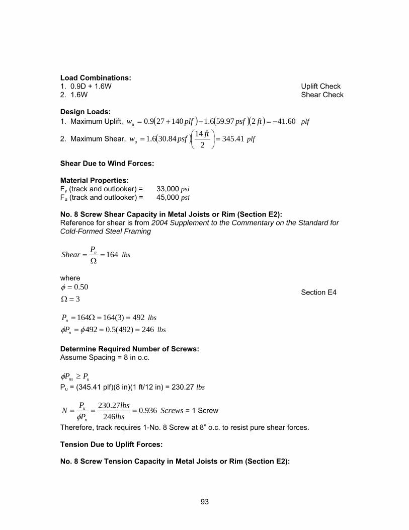
Load Combinations: 1. 0.9D + 1.6W Uplift Check 2. 1.6W Shear Check Design Loads: 1. Maximum Uplift, ( ) ( )( ) 60.41297.596.1140279.0 −=−+= ftpsfplfwu plf
2. Maximum Shear, ( ) 41.3452
1484.306.1 =⎟⎠⎞
⎜⎝⎛=
ftpsfwu plf
Shear Due to Wind Forces: Material Properties: Fy (track and outlooker) = 33,000 psi Fu (track and outlooker) = 45,000 psi No. 8 Screw Shear Capacity in Metal Joists or Rim (Section E2): Reference for shear is from 2004 Supplement to the Commentary on the Standard for Cold-Formed Steel Framing
164=Ω
= nPShear lbs
where
350.0
=Ω=φ
Section E4
492)3(164164 ==Ω=nP lbs
246)492(5.0492 === φφ nP lbs Determine Required Number of Screws: Assume Spacing = 8 in o.c.
uns PP ≥φ Pu = (345.41 plf)(8 in)(1 ft/12 in) = 230.27 lbs
936.0246
27.230===
lbslbs
PP
Nn
u
φ Screws = 1 Screw
Therefore, track requires 1-No. 8 Screw at 8” o.c. to resist pure shear forces. Tension Due to Uplift Forces: No. 8 Screw Tension Capacity in Metal Joists or Rim (Section E2):
93
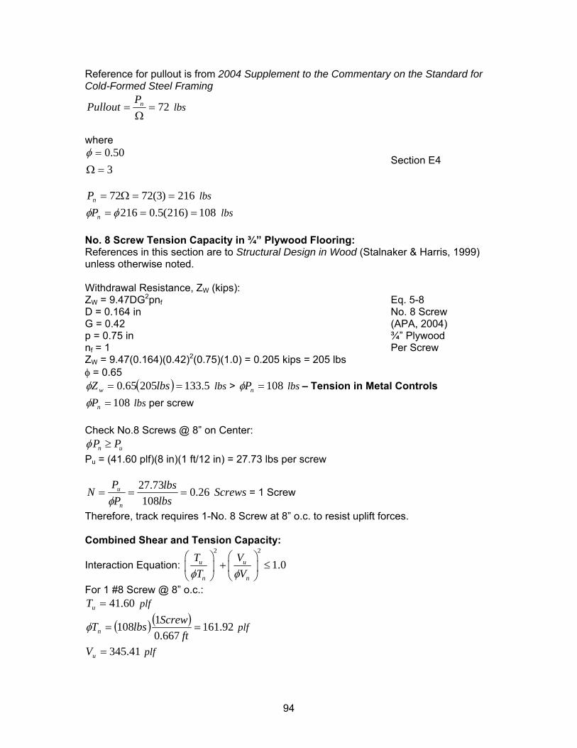
Reference for pullout is from 2004 Supplement to the Commentary on the Standard for Cold-Formed Steel Framing
72=Ω
= nPPullout lbs
where
350.0
=Ω=φ
Section E4
216)3(7272 ==Ω=nP lbs
108)216(5.0216 === φφ nP lbs No. 8 Screw Tension Capacity in ¾” Plywood Flooring: References in this section are to Structural Design in Wood (Stalnaker & Harris, 1999) unless otherwise noted. Withdrawal Resistance, ZW (kips): ZW = 9.47DG2pnf Eq. 5-8 D = 0.164 in No. 8 Screw G = 0.42 (APA, 2004) p = 0.75 in ¾” Plywood nf = 1 Per Screw ZW = 9.47(0.164)(0.42)2(0.75)(1.0) = 0.205 kips = 205 lbs φ = 0.65
( ) 5.13320565.0 == lbsZ wφ lbs > 108=nPφ lbs – Tension in Metal Controls 108=nPφ lbs per screw
Check No.8 Screws @ 8” on Center:
nP Puφ ≥ Pu = (41.60 plf)(8 in)(1 ft/12 in) = 27.73 lbs per screw
26.0108
73.27===
lbslbs
PP
Nn
u
φ Screws = 1 Screw
Therefore, track requires 1-No. 8 Screw at 8” o.c. to resist uplift forces. Combined Shear and Tension Capacity:
Interaction Equation: 2 2
1.0u u
n n
T VT Vφ φ
⎛ ⎞ ⎛ ⎞+ ≤⎜ ⎟ ⎜ ⎟
⎝ ⎠ ⎝ ⎠
For 1 #8 Screw @ 8” o.c.: 60.41=uT plf
( ) ( ) 92.161667.0
1108 ==ft
ScrewlbsTnφ plf
41.345=uV plf
94
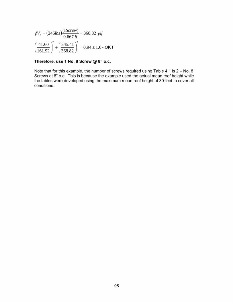
( ) 82.368667.0
)1(246 ==ft
ScrewlbsVnφ plf
0.194.082.36841.345
92.16160.41 22
≤=⎟⎠⎞
⎜⎝⎛+⎟
⎠⎞
⎜⎝⎛ - OK !
Therefore, use 1 No. 8 Screw @ 8” o.c. Note that for this example, the number of screws required using Table 4.1 is 2 – No. 8 Screws at 8” o.c. This is because the example used the actual mean roof height while the tables were developed using the maximum mean roof height of 30-feet to cover all conditions.
95
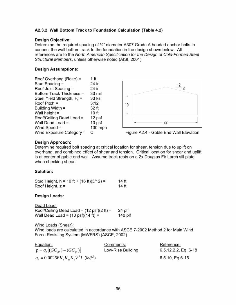
A2.3.2 Wall Bottom Track to Foundation Calculation (Table 4.2) Design Objective: Determine the required spacing of ½” diameter A307 Grade A headed anchor bolts to connect the wall bottom track to the foundation in the design shown below. All references are to the North American Specification for the Design of Cold-Formed Steel Structural Members, unless otherwise noted (AISI, 2001) Design Assumptions: Roof Overhang (Rake) = 1 ft Stud Spacing = 24 in Roof Joist Spacing = 24 in Bottom Track Thickness = 33 mil Steel Yield Strength, Fy = 33 ksi Roof Pitch = 3:12 Building Width = 32 ft Wall height = 10 ft Roof/Ceiling Dead Load = 12 psf Wall Dead Load = 10 psf Wind Speed = 130 mph Wind Exposure Category = C Figure A2.4 - Gable End Wall Elevation Design Approach: Determine required bolt spacing at critical location for shear, tension due to uplift on overhang, and combined effect of shear and tension. Critical location for shear and uplift is at center of gable end wall. Assume track rests on a 2x Douglas Fir Larch sill plate when checking shear.
10'
123
32'
Solution: Stud Height, h = 10 ft + (16 ft)(3/12) = 14 ft Roof Height, z = 14 ft Design Loads: Dead Load: Roof/Ceiling Dead Load = (12 psf)(2 ft) = 24 plf
Wall Dead Load = (10 psf)(14 ft) = 140 plf
Wind Loads (Shear): Wind loads are calculated in accordance with ASCE 7-2002 Method 2 for Main Wind Force Resisting System (MWFRS) (ASCE, 2002). Equation: Comments: Reference:
[ ])()( pipfh GCGCqp −=
dV I
Low-Rise Building 6.5.12.2.2, Eq. 6-18 20.00256h z ztq K K K= (lb/ft2) 6.5.10, Eq 6-15
96
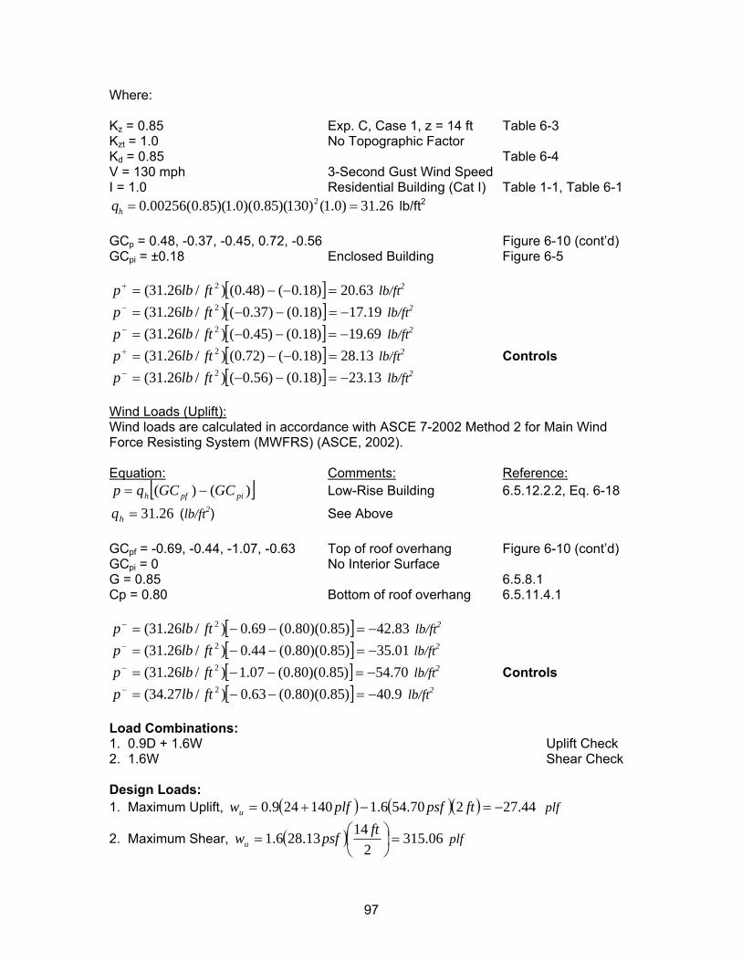
Where:
Kz = 0.85 Exp. C, Case 1, z = 14 ft Table 6-3 Kzt = 1.0 No Topographic Factor Kd = 0.85 Table 6-4 V = 130 mph 3-Second Gust Wind Speed I = 1.0 Residential Building (Cat I) Table 1-1, Table 6-1
20.00256(0.85)(1.0)(0.85)(130) (1.0) 31.26hq = = lb/ft2
GCp = 0.48, -0.37, -0.45, 0.72, -0.56 Figure 6-10 (cont’d) GCpi = ±0.18 Enclosed Building Figure 6-5
[ ] 63.20)18.0()48.0()/26.31( 2 =−−=+ ftlbp lb/ft2 [ ] 19.17)18.0()37.0()/26.31( 2 −=−−=− ftlbp lb/ft2
[ ] 69.19)18.0()45.0()/26.31( 2 −=−−=− ftlbp lb/ft2
[ ] 13.28)18.0()72.0()/26.31( 2 =−−=+ ftlbp lb/ft2 Controls [ ] 13.23)18.0()56.0()/26.31( 2 −=−−=− ftlbp lb/ft2
Wind Loads (Uplift): Wind loads are calculated in accordance with ASCE 7-2002 Method 2 for Main Wind Force Resisting System (MWFRS) (ASCE, 2002). Equation: Comments: Reference:
[ ])()( pipfh GCGCqp −=
Low-Rise Building 6.5.12.2.2, Eq. 6-18
26.31=hq (lb/ft2) See Above
GCpf = -0.69, -0.44, -1.07, -0.63 Top of roof overhang Figure 6-10 (cont’d) GCpi = 0 No Interior Surface G = 0.85 6.5.8.1 Cp = 0.80 Bottom of roof overhang 6.5.11.4.1
[ ] 83.42)85.0)(80.0(69.0)/26.31( 2 −=−−=− ftlbp lb/ft2
[ ] 01.35)85.0)(80.0(44.0)/26.31( 2 −=−−=− ftlbp lb/ft2
[ ] 70.54)85.0)(80.0(07.1)/26.31( 2 −=−−=− ftlbp lb/ft2 Controls [ ] 9.40)85.0)(80.0(63.0)/27.34( 2 −=−−=− ftlbp lb/ft2
Load Combinations: 1. 0.9D + 1.6W Uplift Check 2. 1.6W Shear Check Design Loads: 1. Maximum Uplift, ( ) ( )( ) 44.27270.546.1140249.0 −=−+= ftpsfplfwu plf
2. Maximum Shear, ( ) 06.3152
1413.286.1 =⎟⎠⎞
⎜⎝⎛=
ftpsfwu plf
97
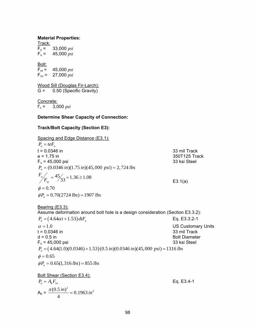
Material Properties: Track: Fy = 33,000 psi Fu = 45,000 psi Bolt: Fnt = 45,000 psi Fnv = 27,000 psi Wood Sill (Douglas Fir-Larch): G = 0.50 (Specific Gravity) Concrete: f’c = 3,000 psi Determine Shear Capacity of Connection: Track/Bolt Capacity (Section E3): Spacing and Edge Distance (E3.1):
n uP teF=
lbs
t = 0.0346 in 33 mil Track e = 1.75 in 350T125 Track Fu = 45,000 psi 33 ksi Steel
(0.0346 )(1.75 )(45,000 ) 2,724nP in in psi= =
45 1.36 1.0833
0.70
u
sy
FF
φ
= = ≥
= E3.1(a)
lbs0.70(2724 ) 1907nP lbsφ = = Bearing (E3.3):
) udtFAssume deformation around bolt hole is a design consideration (Section E3.3.2):
(4.64 1.53nP tα= + Eq. E3.3.2-1 1.0α = US Customary Units
t = 0.0346 in 33 mil Track d = 0.5 in Bolt Diameter Fu = 45,000 psi 33 ksi Steel
( )4.64(1.0)(0.0346) 1.53 (0.5 )(0.0346 )(45,000 ) 1316nP in in= + =psi lbs 0.65φ =
0.65(1,316 ) 855nP lbs lbsφ = = Bolt Shear (Section E3.4):
n b nvP A F= Eq. E3.4-1
Ab = 2
2(0.5 ) 0.19634
in inπ=
98
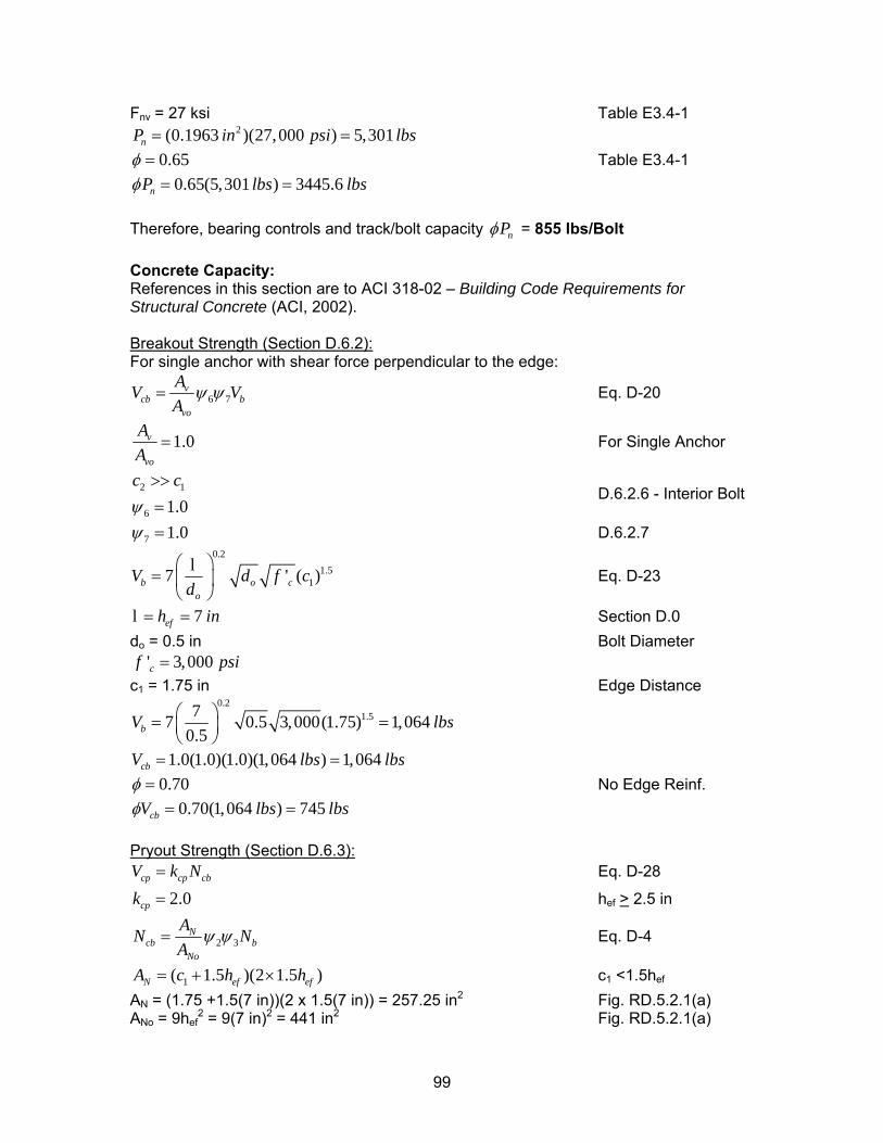
Fnv = 27 ksi Table E3.4-1 2(0.1963 )(27,000 ) 5,301nP in psi= = lbs
0.65φ = Table E3.4-1 0.65(5,301 ) 3445.6nP lbs lbsφ = =
Therefore, bearing controls and track/bolt capacity nPφ = 855 lbs/Bolt Concrete Capacity: References in this section are to ACI 318-02 – Building Code Requirements for Structural Concrete (ACI, 2002). Breakout Strength (Section D.6.2): For single anchor with shear force perpendicular to the edge:
6 7v
cb bvo
AVA
ψ ψ= V Eq. D-20
1.0v
vo
AA
= For Single Anchor
2 1
6 1.0c cψ
>>=
D.6.2.6 - Interior Bolt
7 1.0ψ = D.6.2.7 0.2
1.517b o
o
V d fd
⎛ ⎞= ⎜ ⎟
⎝ ⎠
l ' ( )c c
in
Eq. D-23
7efh= =l Section D.0 do = 0.5 in Bolt Diameter
' 3,000cf psi= c1 = 1.75 in Edge Distance
0.21.577 0.5 3,000(1.75) 1,064
0.5bV l⎛ ⎞= =⎜ ⎟⎝ ⎠
bs
lbs
1.0(1.0)(1.0)(1,064 ) 1,064cbV lbs= = 0.70φ = No Edge Reinf.
0.70(1,064 ) 745cbV lbs lbsφ = = Pryout Strength (Section D.6.3):
cp cp cbV k N= Eq. D-28
2.0cpk = hef > 2.5 in
2 3N
cb bNo
ANA
ψ ψ= N
ef
Eq. D-4
1( 1.5 )(2 1.5 )N efA c h h= + × c1 <1.5hef
AN = (1.75 +1.5(7 in))(2 x 1.5(7 in)) = 257.25 in2 Fig. RD.5.2.1(a) ANo = 9hef
2 = 9(7 in)2 = 441 in2 Fig. RD.5.2.1(a)
99
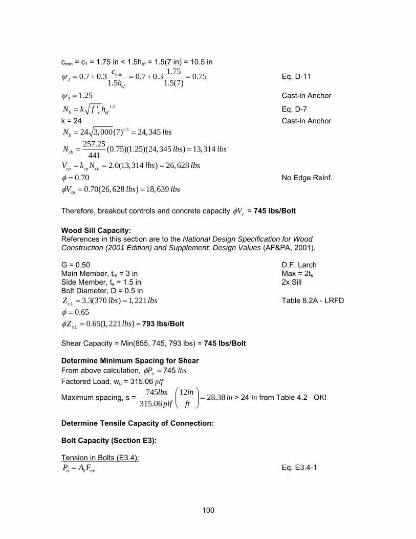
cmin = c1 = 1.75 in < 1.5hef = 1.5(7 in) = 10.5 in
min2
1.750.7 0.3 0.7 0.3 0.751.5 1.5(7)ef
ch
ψ = + = + = Eq. D-11
3 1.25ψ = Cast-in Anchor 1.5'b cN k f h= ef Eq. D-7
k = 24 Cast-in Anchor 1.524 3,000(7) 24,345bN l= = bs
257.25 (0.75)(1.25)(24,345 ) 13,314441cbN lb= s lbs=
s
2.0(13,314 ) 26,628cp cp cbV k N lbs lb= = = 0.70φ = No Edge Reinf.
0.70(26,628 ) 18,639cpV lbs lbsφ = = Therefore, breakout controls and concrete capacity cVφ = 745 lbs/Bolt Wood Sill Capacity: References in this section are to the National Design Specification for Wood Construction (2001 Edition) and Supplement: Design Values (AF&PA, 2001). G = 0.50 D.F. Larch Main Member, tm = 3 in Max = 2ts Side Member, ts = 1.5 in 2x Sill Bolt Diameter, D = 0.5 in
3.3(370 ) 1,221sZ lbs lbs⊥ = = Table 8.2A - LRFD 0.65φ =
0.65(1,221 )sZ lbsφ ⊥ = = 793 lbs/Bolt Shear Capacity = Min(855, 745, 793 lbs) = 745 lbs/Bolt Determine Minimum Spacing for Shear From above calculation, =nPφ 745 lbs Factored Load, wu = 315.06 plf
Maximum spacing, s = 38.281206.315
745=⎟⎟
⎠
⎞⎜⎜⎝
⎛ftin
plflbs
in > 24 in from Table 4.2– OK!
Determine Tensile Capacity of Connection: Bolt Capacity (Section E3): Tension in Bolts (E3.4):
n b nvP A F= Eq. E3.4-1
100
Ab = 2
2(0.5 ) 0.19634
in inπ=
Fnv = 45,000 psi Table E3.4-1 2(0.1963 )(45,000 ) 8,833nP in psi= = lbs
0.65φ = Table E3.4-1 0.65(8,833 ) 5,741.8nP lbs lbsφ = =
Concrete Capacity: References in this section are to ACI 318-02 – Building Code Requirements for Structural Concrete (ACI, 2002). Breakout Strength (Section D.5.2): For single anchor with shear force perpendicular to the edge:
2 3N
cb bNo
ANA
ψ ψ= N
lbs
Eq. D-4
13,314cbN = From Above 0.70φ =
0.70(13,314 ) 9,319.8cbN lbs lbsφ = = Pullout Strength (Section D.5.3):
N4pn pN ψ= Eq. D-12
4 1.0ψ = 8 'p brgN A f= c Eq. D-13
22(.875 ) 0.6013
4brginA iπ
= = n
lbs
Headed Area (AISC, 2001)
f’c = 3,000 psi 20.6013 (8)(3,000 ) 14, 431pN in psi= =
0.70φ = lbs0.70(14,431 ) 10,102.2pN lbsφ = =
Side Face Blowout Strength (Section D.5.4): c = 1.75 in < 0.4hef = 0.4(7 in) = 2.8 in
160 'sb brgN c A= cf
in
Eq. D-15 20.6013brgA = See Above
f’c = 3,000 psi 160(1.75) 0.6013 3,000 11,892sbN = lbs= Eq. D-15
0.70φ = 0.70(11,892 ) 8,324.6pN lbs lbsφ = =
Therefore, side face blowout controls and concrete capacity n pP Nφ φ= = 8,324 lbs/Bolt Tensile Capacity = Min(5741, 8324 lbs) = 5,741 lbs/Bolt
101
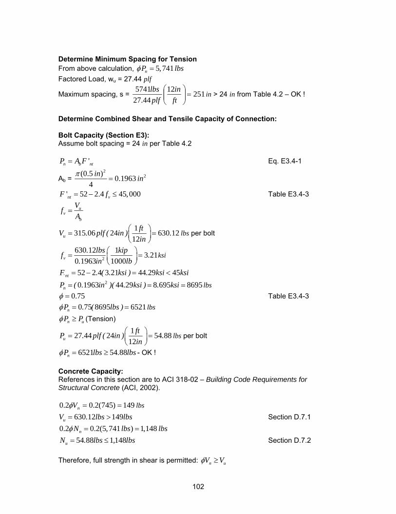
Determine Minimum Spacing for Tension From above calculation, 5,741nP lbsφ = Factored Load, wu = 27.44 plf
Maximum spacing, s = 2511244.27
5741=⎟⎟
⎠
⎞⎜⎜⎝
⎛ftin
plflbs
in > 24 in from Table 4.2 – OK !
Determine Combined Shear and Tensile Capacity of Connection: Bolt Capacity (Section E3): Assume bolt spacing = 24 in per Table 4.2
'n bP A F= nt Eq. E3.4-1
Ab = 2
2(0.5 ) 0.19634
in inπ=
' 52 2.4 45,000nt vF f= − ≤ Table E3.4-3
uv
b
VfA
=
1315 06 24 630 1212u
ftV . plf ( in ) .in
⎛ ⎞= =⎜ ⎟⎝ ⎠
lbs per bolt
2
630 12 1 3 210 1963 1000v
. lbs kipf .. in lb
⎛ ⎞= =⎜ ⎟⎝ ⎠
ksi
52 2 4 3 21 44 29 45' ntF . ( . ksi ) . ksi= − = < ksi= lbs
20 1963 44 29 8 695 8695nP ( . in )( . ksi ) . ksi= =
0.75φ = Table E3.4-3 0 75 8695 6521nP . ( lbs )φ = = lbs
nP Puφ ≥ (Tension)
127 44 24 54 8812u
ftP . plf ( in ) .in
⎛ ⎞= =⎜ ⎟⎝ ⎠
lbs per bolt
6521 54 88nP lbs . lbsφ = ≥ - OK ! Concrete Capacity: References in this section are to ACI 318-02 – Building Code Requirements for Structural Concrete (ACI, 2002).
149)745(2.02.0 ==nVφ lbs 630 12 149uV . lbs l= > bs
lbs Section D.7.1
0.2 0.2(5,741 ) 1,148nN lbsφ = = 54 88 1 148uN . lbs , l= ≤ bs Section D.7.2
Therefore, full strength in shear is permitted: n uV Vφ ≥
102
Maximum spacing = 28.38 in (from shear) > 24 in from Table 4.2 Therefore, use ½” φ headed anchor bolts @ 2’ -0” o.c. as indicated in Table 4.2
103
1201 15th Street, NW
Suite 320
Washington, DC 20005
www.steelframing.org
American Iron and Steel Institute
1140 Connecticut Avenue, NW
Suite 705
Washington, DC 20036
www.steel.org
Re
se
arc
h R
ep
ort
RP
-05
-2