RESEARCH ON TESTING & FP7 BASTION CEBE-P6 Artur Jutman.
28
RESEARCH ON TESTING & FP7 BASTION CEBE-P6 Artur Jutman
-
Upload
maverick-salters -
Category
Documents
-
view
216 -
download
0
Transcript of RESEARCH ON TESTING & FP7 BASTION CEBE-P6 Artur Jutman.

RESEARCH ON TESTING & FP7 BASTION
CEBE-P6
Artur Jutman

Presentation Outline
No Trouble Found
Embedded Instrumentation
Fault Management against Ageing
Test System for LHC at CERN
FP7 BASTION
A. Jutman CEBE Workshop & IAB, Tallinn, Sept 16, 2013
2

Motivation: No Trouble Found – NTF
• NTF symptoms– System passes all tests in the production– System fails at the customer– Troubleshooting cannot repeat the failing condition
• 70% of all product returns characterized as NTF (US, 2008)
• an average family (in US) spends annually 65$ on NTF investigations
3

Testability Problem: good old days
4
PCBA
ICIC
Simple ICs described by functional/truth
tables
Sufficient number of test
points

Testability Problem: today
5
PCBA
BLACK HOLE 2
BLACK HOLE 1
BLACK HOLE 3
Defects might be hiding inside
(behind the horizon)
Defects might be spread among the chips (mismatch)
Dynamic defects on the board not covered
with functional test
NO TROUBLE FOUND?

NTF Cause – Dynamic Faults?
6
• Working Hypothesis– Conclusion: quality of the existing tests is low– Main hypothesis: good test methodology for
dynamic faults is missing
Test Method Target Faults
Test Access Diagnostics Coverage
Structural Static only Scan test, JTAG, intrusive
Good Good but static only
Functional Dynamic Functional code + external measurements
No (pass/fail only)
Unknown
Dream Dynamic Non-intrusive
Good Good (static + dynamic)

Existing Test Coverage Metrics
7
MPS PPVS PCOLA/SOQ
Material Value Correct
Live
Placement
Presence Presence
Alignment
Polarity Orientation
Solder Solder Short
Open
Quality
• Good quality?• Defect free?• Within parametric
tolerances?• How to test?
• Might be expensive to guarantee and measure
Live
Quality
Coverage of dynamic faults is missing!

EMBEDDED INSTRUMENTATION
Some Results
8

Embedded Instrumentation for Test Access
9
FPGA
JTAG
NOR FLASH
I2CI/O I/O
NAND FLASH
SPI FLASH
μPSRAM
We assume the system has a JTAG port, and a programmable device

Embedded Instrumentation on FPGA A new class of instrumentation has been proposed
Embedded virtual instrumentation (EU+US pat. applications) Allows full automation of design, integration, test
Developed instrument examples BERT, at-speed test, frequency measurement, etc. High-speed in-system programming (flash ICs)
10
Instruments
External Embedded
Traditional Virtual Synthetic Traditional Virtual Synthetic
10

JTAG-controlled FPGA Instruments
11

Microprocessor as an Embedded Tester
12
Custom DeviceCommunication
protocol
BusM
atrix
ROM
SRAM
External Bus IF
Peripherial Bridge
NAND flash IF
SDRAMContr.
PDC1 PDC2Proc
esso
r cor
eBu
s int
erfa
ce
Deb
ug m
odul
e
TAP
TDI
TDO
TCK
TRST
TMS
NANDFLASH
SDRAM
AnalogDevice
USBDevice
CustomDevice
CustomDevice
JTAG
Test Access model
Represent the system as a set of tightly interrelated models
Components described using Ec-lipse Modeling Framework (EMF)
Use the models to Generate testware Create a test access path Run test and debug routines
Use HLDDs at all levels as a traversable uniform model
Lego-Style System Modeling

System UnderTest
PCBA BOARD
HEADER
UUT2UUT1
UU
T3
FPGA
Embedded Synthetic
Instruments
InstrumentCard
FPGAProgram
mable IO
Adaptive Test Bus
Controller
General purpose IO instrument card from National Instruments
FPGA on the customer board
becomes an embbedded
testerProgrammable FPGA on the card
becomes an adaptive test bus controller
JTAG standard bus can be used to
communicate between the two
couterparts
The test object – Unit Under Test
Part of general purpose IO
configured as a Test Bus
Typical general purpose functional tester
Customer’s board under test
External PC with control software
13
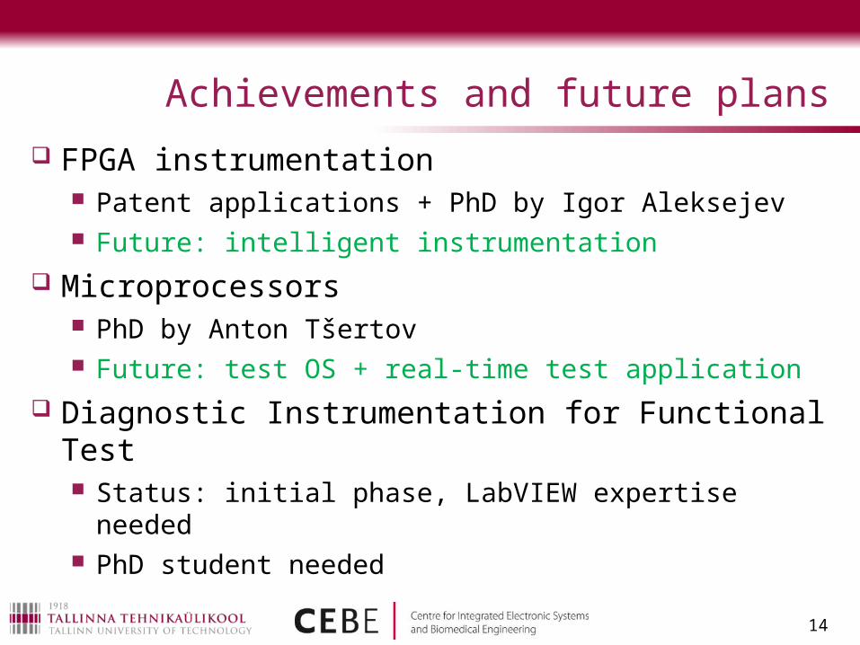
Achievements and future plans
FPGA instrumentation Patent applications + PhD by Igor Aleksejev Future: intelligent instrumentation
Microprocessors PhD by Anton Tšertov Future: test OS + real-time test application
Diagnostic Instrumentation for Functional Test Status: initial phase, LabVIEW expertise needed PhD student needed
14
FAULT MANAGEMENT AGAINST AGEING
15

A Fault Tolerant System
16
Reso-urce 1OS + Scheduler
Activity Map
Interrupts
Reso-urce 2
Reso-urce N
BIST/BISD, DFT, Fault tolerance machanisms
…System
Bus

17
FM: Going Beyond the Correction
Fault Management (FM) provides co-operation between Fault Tolerance and Resource Management
Failure Resilience = Fault Tolerance + Fault Management + Resource Management
Both online and partly offline (core-wise) procedures combined
Fault detection and recovery/correction is NOT enough
Fault Manage-ment
Fault Tolerance
Fault Detection
Data Recovery/ Rollback
Fault Diagnosis/ Classification
Core/Module Isolation
Statistics Collection
Resource Health Map(for Resource Management)

Fault Management Infrastructure
18
Reso-urce 1
Fault Manager
OS + Scheduler
Activity Map
System Health Map
Instrument Manager
(IM)DATA
Interrupts
TAPP1687
MUX
Board HeaderJTAG
Minimal top-level
architecture
FC
X
Reso-urce 2
Reso-urce N
Instrument sub-chains
SIB
…
Resource Manager
(RM)
SystemBus
Status register:
failure, corrected, inactiveF C X
SIB - Select Instrument Bit

Logarithmic Scaling
19
0 200 400 600 800 1000 12000
50
100
150
200
250
300
350
# of fault monitors (instruments)
Fa
ult
Lo
ca
liza
tio
n S
pe
ed
(C
loc
k c
yc
les
Tw
ors
t)

Achievements and future plans
Status IEEE Design and Test journal paper PhD thesis under preparation Future: experimental FPGA/ASIC, optimization for target
application profiles
20
TEST SYSTEM FOR LHC AT CERN
BER Test equipment for the communication channel of CMS
21

Communication Channel Under Test
22
Compact Muon Solenoid(CMS)
Source: http://cms.web.cern.ch/news/how-cms-detects-particles
ROS
On-detector
electronics (CMS)
TSC
Copper twisted pairs
Optical Fiber
Signal translation boards
CMS ROS: 240 Mbps CMS TSC: 480 Mbps
ROS – Read Out ServerTSC – Trigger Sector Collector
Data acquisition system
Copper twisted pairs

Developed BER Test Equipment
23
Transmitter and test generator
Receiver and BER counter
Channel under test
NB! Real channel:
Copper twisted pairs: 40m
Optical Fiber: 60m
BER Test algorithms – developed by CEBE engineersHardware design and implementation – Testonica Lab + ELIKOSoftware and final integration – Testonica Lab
BER – Bit Error Rate

FP7 BASTIONBoard and SoC Test Instrumentation for Ageing and No Failure Found
24

Focus Targets of BASTION
The 2012 ITRS lists ageing (NBTI, PBTI, HCI, etc.) in semiconductor devices as one of the few most difficult challenges of process integration that affects reliability.
NFF is being increasingly reported by industry and according to Accenture Report, in 2008 in US, around 70% of all product returns were characterized as NFF. Cost-wise (including returns processing, scrap and liquidation), NFF amounted up to 50% of total 13.8 billion USD (10.5 billion EUR) returns and repairs cost in US, which approximates to 25 USD (19 EUR) per year per capita.
25

BASTION:Research Targets and Outcomes
26
Application Domain
Basic TechnologyKey Focus: Ageing
Research targets from Call 11:decreased reliability;
ageing effects;heterogeneous SOC integration
Key Focus: No Failure FoundResearch targets from Call 11:
modeling for new materials, processes and devices;
system modeling and simulation
WP1: Fault characterization
and test coverage metrics
WP3: Hierarchical in-field ageing test
and monitoring
WP4: Instrument-Assisted Testing
for NFF
WP2: Embedded instrumentation
networks
Mainly chip-level, in-field test, and monitoring
Mainly board-level, manufacturing test
Gra
cefu
l deg
ra-
datio
n of
SoC
sRe
ducti
on o
f N
FF im
pact

BASTION Consortium Composition
27
Tool VendorsUniversities
Hamm-LippstadtLundTallinnTorinoTwente
End Users
ASTER Technologies
InfineonTestonica Lab
Project results exploitation value chain: partners, technologies, tools

THANK YOU!
28