Research on Electronic Brake Force Distribution and Anti ...
8
Copyright 2020 Society of Automotive Engineers of Japan, Inc. All rights reserved Research on Electronic Brake Force Distribution and Anti-Lock Brake of Vehicle Based on Direct Drive Electro Hydraulic Actuator Xiaoxiang Gong 1) Lixia Qian 1) Weiguo Ge 2) Juan Yan 2) 1) Chongqing Engineering Research Center for Advanced Intelligent Manufacturing Technology, Chongqing Three Gorges University, 666 Tianxing, Wanzhou, 404000, China (Email: [email protected]) 2) Chongqing Engineering Technology Research Center for Light Alloy and Processing, Chongqing Three Gorges University, 666 Tianxing, Wanzhou, 404000, China Received on December, 27, 2019 ABSTRACT In order to effectively improve the vehicle safety, this paper proposed an electronic brake force distribution scheme and an anti-lock brake scheme for passenger car based on a novel brake-by-wire system. The brake-by-wire system was introduced at first, then the electronic brake force distribution scheme and anti-lock brake scheme are designed after analyzing of brake system and vehicle model. At last, the experiment is accomplished to prove the feasibility of the novel brake-by-wire actuator, and the co-simulations of vehicle based on Matlab/Simulink and AMESim are accomplished for typical braking process to prove the superiority of proposed brake-by-wire system and brake scheme. On the one hand, the experiment and simulation results show that the proposed electronic brake force distribution scheme is able to distribute the braking force according to braking intensity and conditions. So the β curve can as close as possible to the I curve. On the other hand, the anti-lock brake scheme is able to accurately regulate the wheel slip rate and adapt to different brake intensity. So the anti-lock brake scheme processes strong robust performance. KEY WORDS: brake-by-wire, linear motor, electric brake force distribution, anti-lock brake, fuzzy control (B1) 1. Introduction Brake-by-wire (BBW) system is one of the key safety technologies since the invention of anti-lock brake system (ABS), because it provides better performance for passenger cars than traditional hydraulic brake system (1) . At present, two main types of BBW system have been extensively studied, which are electro- hydraulic brake (EHB) and electro-mechanical brake (EMB) (2, 3) . Since the mechanical and hydraulic link parts between the brake pedal and wheel actuator are abandoned, the brake signals and electrical energy are transferred by wires and cables in BBW system. Therefore, the braking force distribution between four wheels is no longer restricted by the hydraulic structure, the brake force of every wheel are able to be adjusted independently and the braking process of vehicle can be flexibly adjusted (4) . Although the performance of BBW is higher than hydraulic brake system, the braking performance and direction stability depend not only on the BBW performance, but also on the braking force distribution scheme and anti-lock brake scheme (5) . In addition, the regenerative efficiency of electric vehicle also depends on the braking force distribution scheme (6) . In order to take full advantage of BBW, Yong et al. designed a braking force observer and a robust slip rate controller for EHB to effectively improve the wheel’s anti-lock braking performance (7) . Michael et al. also developed an anti-lock braking strategy for EHB, which keeps the slip rate at the optimal value whether the road is ice, snow or wet (8) . For EMB, Yang et al. designed the electronic braking force distribution (EBD) scheme that can ideally distribute the braking force between the front and rear axles, and proposed the fuzzy ABS algorithm that can accurately control each wheel’s slip ratio and has strong robustness (9) . Daegun et al. designed the wheel slip rate controller by utilizing BBW actuator and sliding mode control method, and proposed the slip rate distribution scheme to maintain vehicle stability based on the fuzzy logic controller and direct yaw moment controller (10) . In addition, the vehicle state observer and slip-rate controller were designed by Andre et al. to improve the braking stability (11) . The generic continuous time model predictive control (MPC) algorithm for vehicle was proposed by Chris et al. to enhance the anti-lock braking performance of EMB (12) . In order to further improve the braking performance and braking stability, a novel BBW actuator based on linear motor is designed in this paper, and a complete BBW system is constructed based on the actuator. Because the proposed BBW system has the advantages of integrating EBD and ABS, the EBD strategy based on ideal braking force distribution and the ABS strategy based on fuzzy controller are studied in detail. Subsequently, the feasibility and performance of BBW actuator are verified by simulation and experiment. Finally, the co-simulation model based on Simulink and AMESim is established to verify the EBD and ABS performance under typical braking condition. 2. The Brake-by-Wire System 2.1. Direct-drive electro-hydraulic brake actuator The brake-by-wire actuator proposed by our team is driven by a linear motor and is named as direct-drive electro-hydraulic brake (DDEHB) actuator (13, 14) , as shown in Fig. 1. In the Fig. 1, 1 is the inner core of line motor, 2 is the shell, and 8 is the end cover, they are all made of low carbon steel and have good magnetic permeability. The ring-shaped permanent magnets 3 and arc-shaped permanent magnets 5 arranged in Halbach array are attached to the inner surface of shell. The magnetic field direction of the ring-shaped magnet is axial, the direction of the arc-shaped magnet is radial, which are shown in the Fig. 1. Between the magnets and the inner core is coil bobbin 6 that moves axially and has two coils 4 and 7 wound in opposite direction. The current directions during braking are shown in Fig. 1 (a) and (b). The plunger 14 is connected to the coil through a pin 15 and moves with the coil. After receiving the brake signal, the energized coil moves to left due to the electromagnetic force, thereby pushing the plunger to compress the brake fluid in the unequal-diameter hydraulic cylinder 13. Subsequently, the compressed brake fluid pushes the piston 12 to the left. The caliper 9 is rigidly connected to the motor body. The two friction linings 10 are arranged symmetrically on both sides of the brake disc 11. The left friction lining is fixed to the caliper 9 and the right friction lining is fixed to the piston. After eliminating the braking gap, the positions of the actuator moving parts are shown in Fig. 1 (b). The friction linings 22 20204228 Xiaoxiang Gong et al / International Journal of Automotive Engineering Vol.11, No.2(2020) Research Paper Copyright © 2020 Society of Automotive Engineers of Japan, Inc. All rights reserved
Transcript of Research on Electronic Brake Force Distribution and Anti ...

Copyright 2020 Society of Automotive Engineers of Japan, Inc. All rights reserved
Research on Electronic Brake Force Distribution and Anti-Lock Brake of
Vehicle Based on Direct Drive Electro Hydraulic Actuator
Xiaoxiang Gong 1) Lixia Qian 1) Weiguo Ge 2) Juan Yan 2) 1) Chongqing Engineering Research Center for Advanced Intelligent Manufacturing Technology, Chongqing Three Gorges
University, 666 Tianxing, Wanzhou, 404000, China (Email: [email protected])
2) Chongqing Engineering Technology Research Center for Light Alloy and Processing, Chongqing Three Gorges University,
666 Tianxing, Wanzhou, 404000, China
Received on December, 27, 2019
ABSTRACT In order to effectively improve the vehicle safety, this paper proposed an electronic brake force distribution
scheme and an anti-lock brake scheme for passenger car based on a novel brake-by-wire system. The brake-by-wire system
was introduced at first, then the electronic brake force distribution scheme and anti-lock brake scheme are designed after
analyzing of brake system and vehicle model. At last, the experiment is accomplished to prove the feasibility of the novel
brake-by-wire actuator, and the co-simulations of vehicle based on Matlab/Simulink and AMESim are accomplished for
typical braking process to prove the superiority of proposed brake-by-wire system and brake scheme. On the one hand, the
experiment and simulation results show that the proposed electronic brake force distribution scheme is able to distribute the
braking force according to braking intensity and conditions. So the β curve can as close as possible to the I curve. On the other
hand, the anti-lock brake scheme is able to accurately regulate the wheel slip rate and adapt to different brake intensity. So the
anti-lock brake scheme processes strong robust performance.
KEY WORDS: brake-by-wire, linear motor, electric brake force distribution, anti-lock brake, fuzzy control (B1)
1. Introduction
Brake-by-wire (BBW) system is one of the key safety
technologies since the invention of anti-lock brake system (ABS),
because it provides better performance for passenger cars than
traditional hydraulic brake system(1). At present, two main types of
BBW system have been extensively studied, which are electro-
hydraulic brake (EHB) and electro-mechanical brake (EMB) (2, 3).
Since the mechanical and hydraulic link parts between the brake
pedal and wheel actuator are abandoned, the brake signals and
electrical energy are transferred by wires and cables in BBW
system. Therefore, the braking force distribution between four
wheels is no longer restricted by the hydraulic structure, the brake
force of every wheel are able to be adjusted independently and the
braking process of vehicle can be flexibly adjusted(4). Although the
performance of BBW is higher than hydraulic brake system, the
braking performance and direction stability depend not only on the
BBW performance, but also on the braking force distribution
scheme and anti-lock brake scheme (5). In addition, the regenerative
efficiency of electric vehicle also depends on the braking force
distribution scheme (6).
In order to take full advantage of BBW, Yong et al. designed
a braking force observer and a robust slip rate controller for EHB
to effectively improve the wheel’s anti-lock braking performance (7). Michael et al. also developed an anti-lock braking strategy for
EHB, which keeps the slip rate at the optimal value whether the
road is ice, snow or wet(8). For EMB, Yang et al. designed the
electronic braking force distribution (EBD) scheme that can ideally
distribute the braking force between the front and rear axles, and
proposed the fuzzy ABS algorithm that can accurately control each
wheel’s slip ratio and has strong robustness (9). Daegun et al.
designed the wheel slip rate controller by utilizing BBW actuator
and sliding mode control method, and proposed the slip rate
distribution scheme to maintain vehicle stability based on the fuzzy
logic controller and direct yaw moment controller (10). In addition,
the vehicle state observer and slip-rate controller were designed by
Andre et al. to improve the braking stability(11). The generic
continuous time model predictive control (MPC) algorithm for
vehicle was proposed by Chris et al. to enhance the anti-lock
braking performance of EMB(12).
In order to further improve the braking performance and
braking stability, a novel BBW actuator based on linear motor is
designed in this paper, and a complete BBW system is constructed
based on the actuator. Because the proposed BBW system has the
advantages of integrating EBD and ABS, the EBD strategy based
on ideal braking force distribution and the ABS strategy based on
fuzzy controller are studied in detail. Subsequently, the feasibility
and performance of BBW actuator are verified by simulation and
experiment. Finally, the co-simulation model based on Simulink
and AMESim is established to verify the EBD and ABS
performance under typical braking condition.
2. The Brake-by-Wire System
2.1. Direct-drive electro-hydraulic brake actuator
The brake-by-wire actuator proposed by our team is driven
by a linear motor and is named as direct-drive electro-hydraulic
brake (DDEHB) actuator (13, 14), as shown in Fig. 1.
In the Fig. 1, 1 is the inner core of line motor, 2 is the shell,
and 8 is the end cover, they are all made of low carbon steel and
have good magnetic permeability. The ring-shaped permanent
magnets 3 and arc-shaped permanent magnets 5 arranged in
Halbach array are attached to the inner surface of shell. The
magnetic field direction of the ring-shaped magnet is axial, the
direction of the arc-shaped magnet is radial, which are shown in
the Fig. 1. Between the magnets and the inner core is coil bobbin 6
that moves axially and has two coils 4 and 7 wound in opposite
direction. The current directions during braking are shown in Fig.
1 (a) and (b). The plunger 14 is connected to the coil through a pin
15 and moves with the coil. After receiving the brake signal, the
energized coil moves to left due to the electromagnetic force,
thereby pushing the plunger to compress the brake fluid in the
unequal-diameter hydraulic cylinder 13. Subsequently, the
compressed brake fluid pushes the piston 12 to the left. The caliper
9 is rigidly connected to the motor body. The two friction linings
10 are arranged symmetrically on both sides of the brake disc 11.
The left friction lining is fixed to the caliper 9 and the right friction
lining is fixed to the piston.
After eliminating the braking gap, the positions of the
actuator moving parts are shown in Fig. 1 (b). The friction linings
22
20204228
Xiaoxiang Gong et al / International Journal of Automotive Engineering
Vol.11, No.2(2020)Research Paper
Copyright © 2020 Society of Automotive Engineers of Japan, Inc. All rights reserved

2
and the brake disc are strongly pressed by the piston. Because the
brake disc rotates with the wheel and the brake lings are fixed, the
friction force is generated between the disc and friction lings,
which slows down the wheel. If the brake state needs to be released,
the coil is energized in the reverse direction and the moving parts
return to the original position, as shown in Fig. 1 (a).
123456789
11 12 13 14
10
15
1,2,8: Motor body 5: Arc-shaped permanent magnet 10: Friction linings 13: Unequal diameter cylinder
3: Ring-shaped permanent magnet 6: Coil bobbin 11: Brake disc 14: Plunger
4,7: Coil 9: Caliper 12: Piston 15: Pin
(a) Unbraking state (b) Braking state
Fig. 1 The principle and structure of direct-drive electro-hydraulic brake actuator
2.2. The vehicle BBW system based on DDEHB
The vehicle braking system composed of DDEHB is shown
in Fig. 2. It is consists of brake pedal simulator, four actuators,
controllers, drivers and sensors. The brake pedal simulator
converts the driver’s actions into electronic signal. And other
signals such as velocity, wheel speeds, steering angle and braking
force are also converted into electronic signals at the same time.
All these signals are delivered to brake system controller. After the
controller analyzes and processes these signals comprehensively,
the braking force distribution strategy allocates the total braking
force to each actuator controller. Thereafter, the actuator controller
adjusts the coil current to provide appropriate braking force for
every wheel based on the received force signal.
DU
U U
U
D
D
D
DDEHB
DC-DC
battery
pedal DDEHB
ECU
v
D:unit driver
U:unit controller :sensors
Fig. 2 EBD/ABS system based on DDEHB unit
DDEHB utilizes linear motor to convert electrical energy
into electromagnetic force, so the structure is simpler than EMB
because the motion conversion mechanism is not necessary in
DDEHB(15). The main advantages are:
a) The brake force is provided by the linear motor without
motion conversion mechanism, so the braking force responds
quickly and the control accuracy is high.
b) The unequal diameter hydraulic cylinder is used to
reduce the size and weight of actuator, so DDEHB is compact and
suitable for various vehicles.
c) The vacuum booster, hydraulic pipelines, ABS module
and other devices are cancelled, so the structure of the brake system
is simpler.
d) The brake force is independently and flexibly adjusted
by DDEHB actuator, so it is easier to adjust the braking process,
such as ABS control and vehicle stability control (VSC).
3. Dynamic Model of DDEHB and Vehicle
3.1. Model of DDEHB
The electric circuit of linear motor can be equivalent to a
closed circuit consisting of inductor, resistor and counter
electromotive force. According to Kirchhoff's voltage law, the total
voltage of closed circuit is zero, which is expressed by the equation
(1).
𝑈(𝑡) = 𝐸 + 𝑅𝑖(𝑡) + 𝐿𝑑𝑖(𝑡)
𝑑𝑡 (1)
Where: i is the coil current; R is the coil resistance; U is the motor
voltage; L is the coil inductance; E is the counter electromotive
force which is calculated as equation (2).
𝐸 = 𝐵𝑙𝑁𝑑𝑥(𝑡)
𝑑𝑡 (2)
Where: B is the magnetic induction intensity; N is the coil turns; l
is the coil lap length.
The energized coil is subjected to electromagnetic force and
moves along the axis. The direction of electromagnetic force is
determined by the Faraday’s left-hand rule, and the value is
determined by equation (3).
23
Xiaoxiang Gong et al / International Journal of Automotive Engineering
Vol.11, No.2(2020)
Copyright © 2020 Society of Automotive Engineers of Japan, Inc. All rights reserved

3
𝐹𝑒 = 𝐵𝑙𝑁𝑖(𝑡) (3)
The plunger is subjected to electromagnetic force and
hydraulic force, which motion is expressed as equation (4).
𝐹𝑒 = 𝑚𝑑2𝑥(𝑡)
𝑑𝑡2+ 𝐶
𝑑𝑥(𝑡)
𝑑𝑡+ 𝐹𝑑 (4)
Where: m is the total mass of coil and plunger; x is the coil
displacement; C is the coil damping coefficient; 𝐹𝑑 is the
equivalent hydraulic force acted on the plunger.
If the secondary factors are ignored, such as process pressure
loss and local pressure loss of hydraulic liquid. The model of
unequal diameter hydraulic cylinder can be simplified to:
𝐹𝐷𝐹𝑑=𝐷2
𝑑2 (5)
Where: FD is the force acted on piston; D and d are the piston
diameter and plunger diameter respectively.
Finally, the braking torque acting on the wheel is:
𝑀 = 2𝑓𝐹𝐷𝑅 (6)
Where: f is the friction coefficient between the braking lings and
brake disc, R is the effective radius of brake disc.
3.2. Dynamics model of vehicle
The external forces acted on the wheel in longitudinal and
vertical during braking are shown in Fig. 3, including vertical
ground reaction force 𝐹𝑍, wheel load 𝑊, ground braking force 𝐹𝑋,
braking torque 𝑀, and axle reaction force 𝐹𝑝.
v
ωT M
W
Fp
FZ
FX
Fig. 3 Wheel force
The braking torque 𝑀 is provided by DDEHB actuator. With
the effect of braking torque 𝑀 and ground braking force 𝐹𝑋, the
dynamic model of wheel is described by equation (7):
𝑀 − 𝑅𝑡𝐹𝑋 = 𝐽𝑡𝑑𝜔𝑡𝑑𝑡
(7)
Where: 𝑅𝑡 is the rolling radius of wheel; 𝐽𝑡 is the wheel inertia; 𝜔𝑡 is the wheel speed.
The force acted on the vehicle during braking are shown in
Fig. 4. If the vehicle vibration, roll, pitch and other secondary
factors are ignored, and the height of vehicle gravity center is h,
steering angle is α, then the vehicle dynamics model is simplified
as equation (8) to (13)(16, 17).
Fj
hRC G
v
FZf
FXf
FZr
FXr
lr lf
l
FX1
FX2
FX3
FX4
FY1
FY2
FY3
FY4
lrlf
l
br bf
α
Fig. 4 Force analysis at braking condition
𝑚(�̇� − 𝑣𝑟) = (𝐹𝑋1 + 𝐹𝑋2) 𝑐𝑜𝑠 𝛼 + (𝐹𝑌1 + 𝐹𝑌2) 𝑠𝑖𝑛 𝛼 + 𝐹𝑋3 + 𝐹𝑋4 (8)
𝑚(�̇� + 𝑢𝑟) = (𝐹𝑌1 + 𝐹𝑌2) 𝑐𝑜𝑠 𝛼 − (𝐹𝑋1 + 𝐹𝑋2) 𝑠𝑖𝑛 𝛼 + 𝐹𝑌3 + 𝐹𝑌4 (9)
𝑚𝑔 = 𝐹𝑍1 + 𝐹𝑍2 + 𝐹𝑍3 + 𝐹𝑍4 (10)
−𝑚(�̇� + 𝑢𝑟)ℎ = (𝐹𝑍1 − 𝐹𝑍2) ∙𝑏𝑓
2+ (𝐹𝑍3 − 𝐹𝑍4) ∙
𝑏𝑟2
(11)
24
Xiaoxiang Gong et al / International Journal of Automotive Engineering
Vol.11, No.2(2020)
Copyright © 2020 Society of Automotive Engineers of Japan, Inc. All rights reserved

4
𝑚(�̇� − 𝑣𝑟)ℎ = −(𝐹𝑍1 + 𝐹𝑍2)𝑙𝑓 + (𝐹𝑍3 + 𝐹𝑍4)𝑙𝑟 (12)
𝐼𝑍�̇� =𝑏𝑓
2[(𝐹𝑋1 − 𝐹𝑋2) 𝑐𝑜𝑠 𝛼 + (𝐹𝑌1 − 𝐹𝑌2) 𝑠𝑖𝑛 𝛼] +
𝑏𝑟2(𝐹𝑋3 − 𝐹𝑋4) + 𝑙𝑓[(𝐹𝑌1 + 𝐹𝑌2) 𝑐𝑜𝑠 𝛼 − (𝐹𝑋1 + 𝐹𝑋2) 𝑠𝑖𝑛 𝛼]
− 𝑙𝑟(𝐹𝑌3 + 𝐹𝑌4) (13)
Where: 𝑚 is the vehicle mass; 𝑢 is the longitudinal velocity; 𝑣 is
the lateral velocity; 𝑟 is the yaw rate; 𝐹𝑋𝑖 is the longitudinal
adhesion force of i wheel; 𝐹𝑌𝑖 is the lateral adhesion force of i
wheel, 𝐹𝑍𝑖 is the vertical force of i wheel, 𝑙𝑓 is the horizontal
distance between the front axle and gravity center; 𝑙𝑟 is the
horizontal distance between the rear axle and gravity center; 𝑏𝑓 is
the front wheel base, 𝑏r is the rear wheel base; 𝐼𝑍 is inertia moment
of vehicle body around the 𝑧 axis
4. The EBD/ABS Control of BBW
4.1. EBD strategy
The EBD system detects the wheel adhesion , automatically
adjusts the braking force distribution ratio between the front and
rear axles and between the left and right wheels. With the aid of
EBD, the braking efficiency is greatly improved, the braking
distance is significantly shortened, the vehicle is kept stable,
therefore the driving safety is greatly improved (18). The existing
EBD strategy usually distributes and regulates brake force
according to the vehicle’s motion state, so that the actual braking
force distribution curve (β curve) is as close as possible to the ideal
braking force distribution curve (I curve). There are three main
strategies for EBD. The first strategy distributes the braking force
according to the rear wheel speed and its reference value. The
second strategy distributes the braking force according to the slip-
ratio of front and rear wheels. And the third strategy distributes the
braking force according to the speeds of front and rear wheels (9).
DDEHB actuator adjusts braking force flexibly and
independently, so the total braking force required by driver is
distributed as I curve between the front and rear axis at first. The
vehicle gravity center is higher than ground, as shown in Fig. 4.
Due to inertia, the vehicle load will be transferred to the front axle
during braking. Therefore, the front axle load is greater than its’
static load, and the rear axle load is less than its’ static load. The
transferred load is:
𝐹𝑗 =𝐺𝑧ℎ
𝑙 (14)
Where: 𝑙 = 𝑙𝑓 + 𝑙𝑟; G is the vehicle gravity; z is the braking strength,
which is defined as the ration of longitudinal deceleration to
gravitational acceleration and expressed as equation (15).
𝑧 =�̇�
𝑔 (15)
The actual front load 𝐹𝑍𝑓 and rear load 𝐹𝑍𝑟 are:
{
𝐹𝑍𝑓 =𝐺(𝑙𝑟 + 𝑧ℎ)
𝑙
𝐹𝑍𝑟 =𝐺(𝑙𝑓 − 𝑧ℎ)
𝑙
(16)
If the friction coefficients between all wheels and the road
are μ, the ground braking force of front and rear axles are :
{
𝐹𝑋𝑓 + 𝐹𝑋𝑟 = 𝑧𝐺
𝐹𝑋𝑓
𝐹𝑋𝑟=𝑙𝑟 + 𝑧ℎ
𝑙𝑓 − 𝑧ℎ
(17)
According to equation (17), the ideal braking force
distribution between front and rear axle is expressed as equation
(18).
𝐹𝑋𝑟 =1
2[𝐺
ℎ√𝑙𝑟
2 +4(𝑙𝑓 + 𝑙𝑟)𝑙ℎ
𝐺𝐹𝑋𝑓 − (
𝐺𝑙𝑟ℎ+ 2𝐹𝑋𝑓)] (18)
Do not consider the steering temporarily, the braking force
allocated on front and rear axle will be evenly distributed to the left
and right wheels:
𝐹𝑋1 = 𝐹𝑋2 =𝐹𝑋𝑓
2 (19)
𝐹𝑋3 = 𝐹𝑋4 =𝐹𝑋𝑟2
(20)
Whether to control the slip-rate depends on the wheels status,
the ABS controller will be activated if the slip-rate of any wheel is
greater than 0.5. thereafter, the slip-rate is regulated back to its
ideal value or set value by adjusting the DDEHB current (19).
4.2. ABS strategy
The slip-rate controller is fuzzy controller, which inputs are
the difference between the actual slip-rate and its ideal value, and
the slip-rate change rate. The calculation and estimation of ideal
slip-rate has been studied by many researchers (6, 20). In this study,
the ideal slip-rate was set to 0.2 in order to reflect the research focus
and simple the description.
{
𝑥1 = ∆𝑠 = 𝑠 − 0.2
𝑥2 =𝑑𝑠
𝑑𝑡
(21)
In which:
s =𝑢 − 𝜔𝑡𝑅𝑡
𝑢 (22)
The output of controller is the increment of braking force ∆𝐹,
the structure of ABS controller is shown in Fig. 5.
ds/dt
Δs
+
-
ΔF
s
Diffe
rential
Fu
zzific
atio
n
Fu
zzific
atio
n
infe
ren
ce
An
ti-
Fu
zzific
atio
n
infe
ren
ce
Vehicle
0.2
Fig. 5 The structure of ABS controller
According to equation (22), the variation range of slip ratio s
is: 0 <s <1, so the domain of 𝑥1 is (-0.2, 0.8). And according to
experience, the domain of 𝑥2 is (-15, 15), the domain of ∆𝐹 is (-90,
90). The fuzzy controller uses fuzzy mind similar to human brain
to regulate the slip rate. In other words, the further the values of 𝑥1
and 𝑥2 are from the stable value 0, the value of ∆𝐹 is greater.
Defines the fuzzy set: [NB, NM, NS, ZE, PS, PM, PB] =
[negative big, negative median, negative small, zero, positive small,
positive median, positive big], and fuzzification map 𝑥1 , 𝑥2 and
∆𝐹 to the above 7 fuzzy set. The fuzzy controller uses Mamdani
fuzzification inference and gravity anti-fuzzification inference to
25
Xiaoxiang Gong et al / International Journal of Automotive Engineering
Vol.11, No.2(2020)
Copyright © 2020 Society of Automotive Engineers of Japan, Inc. All rights reserved
5
calculate the output, and the designed fuzzy control surface is
shown in Fig. 6(21, 22).
-0.2
0
0.2
0.4
0.6
0.8
-15-10
-50
510
15
-60
-40
-20
0
20
40
60
ΔF
Fig. 6 Fuzzy control surface
ΔF
++
Fxi Min
Fig. 7 Braking force selection
The output ∆𝐹 is responsible for adjusting the wheel slip rate.
If the slip rate is always maintained at its optimal value, the actual
deceleration will be greater than the required deceleration during
normal braking. Therefore, the actual braking force acted on the
wheels is shown in Fig. 7, the minimum value should be taken from
the output of slip rate controller and braking force distribution
controller.
5. Simulation and Experiment of EBD/ABS
5.1. Simulation and experiment of DDEHB
In order to verify the feasibility of the braking scheme
proposed in this paper, the performance of DDEHB actuator was
first verified by simulation and experiment. The caliper of DDEHB
used in the experiment was modified from a traditional hydraulic
brake unit. The linear motor was machined according to Fig. 1, and
then the caliper and linear motor were rigidly connected as a whole
by bolts. The main parameters of the DDEHB and linear motor are
shown in Table 1 and Table 2 respectively. At the same time, the
Simulink model is also established to simulate the performance of
DDEHB(23).
Table 1 Parameters of DDEHB
Parameter Value
Piston diameter (mm) 38
Plunger diameter (mm) 6
Max pressure (MPa) 10
Max braking force (N) 10343 (μ=0.38)
Max piston pressure (N) 27219
Electromagnetic force (N) 339
Table 2 Parameters of linear motor
Parameter Value
EMLA diameter (mm) 60
EMLA length (mm) 70
EMLA voltage (V) 24
Coil resistance (Ω) 0.7615
Coil inductance (μH) 279.8
Peak current (A) 20
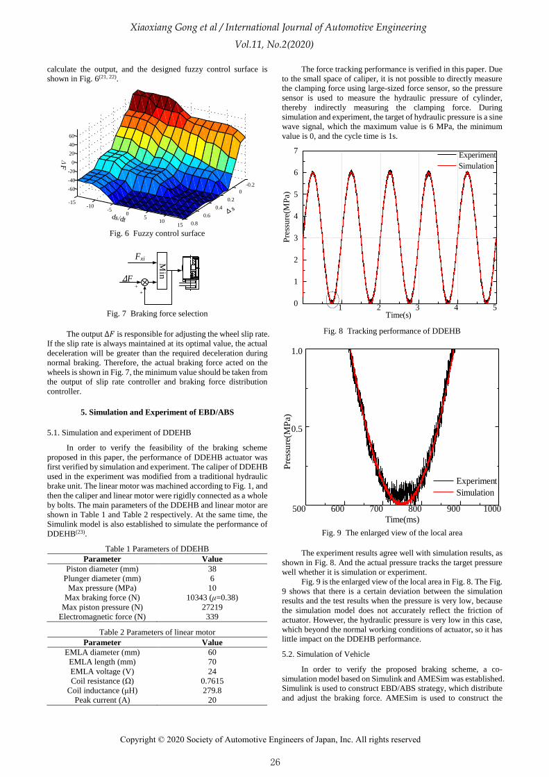
The force tracking performance is verified in this paper. Due
to the small space of caliper, it is not possible to directly measure
the clamping force using large-sized force sensor, so the pressure
sensor is used to measure the hydraulic pressure of cylinder,
thereby indirectly measuring the clamping force. During
simulation and experiment, the target of hydraulic pressure is a sine
wave signal, which the maximum value is 6 MPa, the minimum
value is 0, and the cycle time is 1s.
1 2 3 4 50
1
2
3
4
5
6
7
Pre
ssure
(MP
a)
Time(s)
Experiment
Simulation
Fig. 8 Tracking performance of DDEHB
500 600 700 800 900 1000
0.5
1.0
Pre
ssu
re(M
Pa)
Time(ms)
Experiment
Simulation
Fig. 9 The enlarged view of the local area
The experiment results agree well with simulation results, as
shown in Fig. 8. And the actual pressure tracks the target pressure
well whether it is simulation or experiment.
Fig. 9 is the enlarged view of the local area in Fig. 8. The Fig.
9 shows that there is a certain deviation between the simulation
results and the test results when the pressure is very low, because
the simulation model does not accurately reflect the friction of
actuator. However, the hydraulic pressure is very low in this case,
which beyond the normal working conditions of actuator, so it has
little impact on the DDEHB performance.
5.2. Simulation of Vehicle
In order to verify the proposed braking scheme, a co-
simulation model based on Simulink and AMESim was established.
Simulink is used to construct EBD/ABS strategy, which distribute
and adjust the braking force. AMESim is used to construct the
26
Xiaoxiang Gong et al / International Journal of Automotive Engineering
Vol.11, No.2(2020)
Copyright © 2020 Society of Automotive Engineers of Japan, Inc. All rights reserved

6
vehicle and DDEHB models(24). In the simulation, the road
adhesion coefficient is set to 0.4, the target deceleration of the first
3 seconds is set to 2m/s2 which verifies the performance of braking
force distribution scheme, and the target deceleration after 3
seconds is changed to 5m/s2 which verifies the performance of anti-
lock braking scheme. The other main parameters used in the
simulation are shown in Table 3.
Table 3 Simulation parameters
Parameter Value
Vehicle mass (Kg) 1430
Front axle base (mm) 1210
Rear axle base (mm) 1230
Gravity height (mm) 490
Target slip-rate 0.2
Brake disc effective radius (mm) 95
Wheel rolling radius (mm) 280
Wheel base (mm) 1450
friction lining factors 0.38
Initial velocity (m/s) 30
The velocity and deceleration are shown in Fig. 10, the
velocity changes evenly and smoothly whether in light braking or
heavy braking. The actual deceleration was accurately maintained
at 2m/s2 in the first 3 seconds, indicating that the deceleration
controller accurately controls the braking strength. The actual
deceleration attempts to reach 5m/s2 after 3 seconds, but the road
does not allow because the adhesion coefficient is only 0.4. The
anti-lock controller was activated in time when controller detects
that the wheels are going to be locked, so the actual deceleration
was adjusted and maintained at 4 m/s2.
0 1 2 3 4 5 6 7 8 9
5
10
15
20
25
30 Velocity
Deceleration
Time (s)
Vel
oci
ty (
ms
-1)
1
2
3
4
5
Dec
eler
atio
n (
ms
-2)
Fig. 10 Velocity and deceleration
0 1 2 3 4 5 6 7 8 9
200
400
600
800
1000
Whee
l sp
eed (
nm
in-1)
Time (s)
Front wheel speed
Rear wheel speed
Fig. 11 Wheel speed
The speed curve changes evenly in overall view, as shown in
Fig. 11. But it decreased rapidly at 3 second because the target
deceleration changes to 5m/s2, especially the front wheel speed
decreases more rapidly even to be locked. After the ABS being
activated, the wheel speeds are adjusted to normal and uniformly
descend until the end of brake process.
Both front and rear slip-rate are low and stable in the first 3
seconds, as shown in Fig. 12, indicating that the vehicle is in a
stable braking conditions. The slip-rates increase rapidly after 3
second due to the abruptly change in the target deceleration,
especially the slip-rate of front wheel quickly exceeded the set
threshold of 0.5. Then the ABS is activated, both the front and rear
slip-rate are adjusted to and maintained at the set value of 0.2.
0 1 2 3 4 5 6 7 8 9
0.1
0.2
0.3
0.4
0.5
0.6
Sli
p-r
ate
Time (s)
Front slip-rate
Rear slip-rate
Fig. 12 Slip-rate
0 1 2 3 4 5 6 7 8 9
1
2
3
4
5
6
7
8
Bra
ke
forc
e (K
N)
Time (s)
Front brake force
Rear brake force
Fig. 13 Braking force provided by DDEHB
The brake force provided by DDEHB are shown in Fig. 13.
After 3 seconds, the braking force increase quickly result in the
wheels being locked. After that, the ABS is activated and the
braking force is adjusted back to the optimal value of current road.
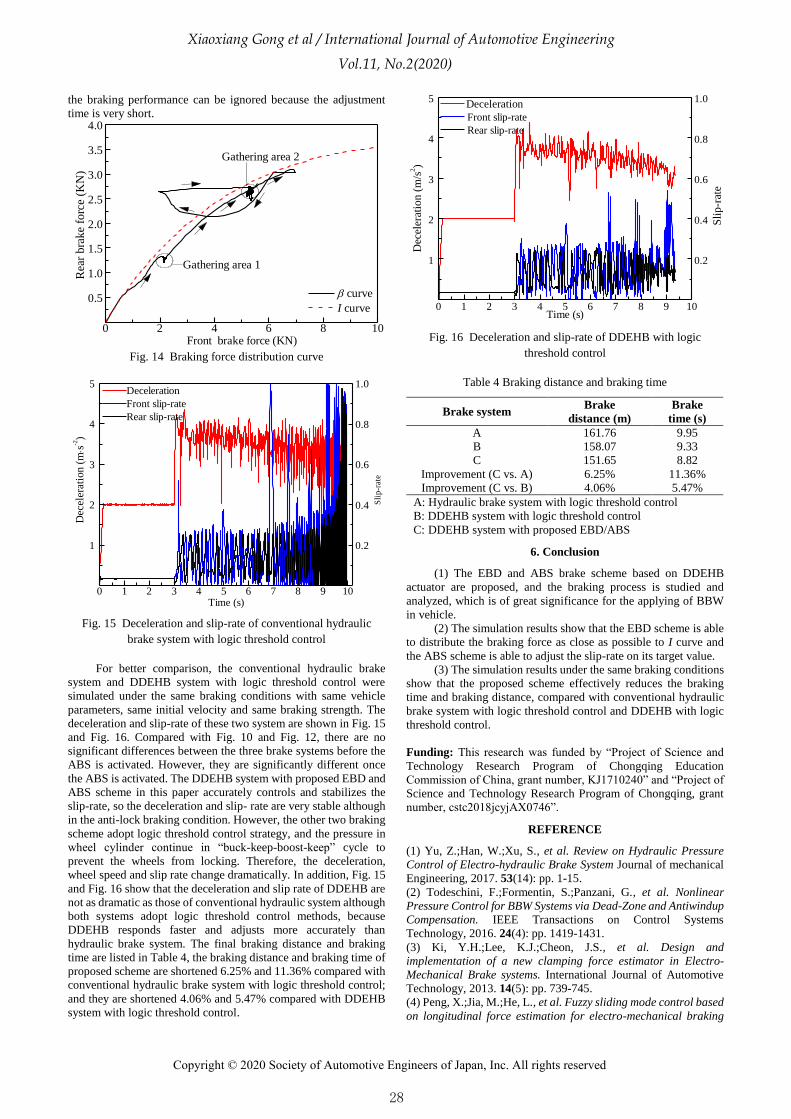
The actual braking force distribution curve (β curve) and
ideal braking force distribution curve (I curve) are shown in Fig.
14. The β curve should be below and as close as possible to I curve.
The actual braking force changes along the arrow, where the
braking force distribution ratio in first 3 seconds and after 3
seconds are mainly concentrated in area 1 and area 2 respectively.
Both regions are below and close to I curve, which indicates that
the proposed distribution scheme is reasonable and feasible. In the
Fig. 14, a part of β curve is higher than I curve, which
corresponding time is 3.24s - 3.37s. it is the braking force
adjustment stage after the anti-lock is activated and the effect on
27
Xiaoxiang Gong et al / International Journal of Automotive Engineering
Vol.11, No.2(2020)
Copyright © 2020 Society of Automotive Engineers of Japan, Inc. All rights reserved
7
the braking performance can be ignored because the adjustment
time is very short.
0 2 4 6 8 10
0.5
1.0
1.5
2.0
2.5
3.0
3.5
4.0
Gathering area 2
Rea
r bra
ke
forc
e (K
N)
Front brake force (KN)
curve
I curve
Gathering area 1
Fig. 14 Braking force distribution curve
0 1 2 3 4 5 6 7 8 9 10
1
2
3
4
5
Time (s)
Dec
eler
atio
n (
ms
-2)
0.2
0.4
0.6
0.8
1.0Deceleration
Front slip-rate
Rear slip-rate
Sli
p-r
ate
Fig. 15 Deceleration and slip-rate of conventional hydraulic
brake system with logic threshold control
For better comparison, the conventional hydraulic brake
system and DDEHB system with logic threshold control were
simulated under the same braking conditions with same vehicle
parameters, same initial velocity and same braking strength. The
deceleration and slip-rate of these two system are shown in Fig. 15
and Fig. 16. Compared with Fig. 10 and Fig. 12, there are no
significant differences between the three brake systems before the
ABS is activated. However, they are significantly different once
the ABS is activated. The DDEHB system with proposed EBD and
ABS scheme in this paper accurately controls and stabilizes the
slip-rate, so the deceleration and slip- rate are very stable although
in the anti-lock braking condition. However, the other two braking
scheme adopt logic threshold control strategy, and the pressure in
wheel cylinder continue in “buck-keep-boost-keep” cycle to
prevent the wheels from locking. Therefore, the deceleration,
wheel speed and slip rate change dramatically. In addition, Fig. 15
and Fig. 16 show that the deceleration and slip rate of DDEHB are
not as dramatic as those of conventional hydraulic system although
both systems adopt logic threshold control methods, because
DDEHB responds faster and adjusts more accurately than
hydraulic brake system. The final braking distance and braking
time are listed in Table 4, the braking distance and braking time of
proposed scheme are shortened 6.25% and 11.36% compared with
conventional hydraulic brake system with logic threshold control;
and they are shortened 4.06% and 5.47% compared with DDEHB
system with logic threshold control.
0 1 2 3 4 5 6 7 8 9 10
1
2
3
4
5 Deceleration
Front slip-rate
Rear slip-rate
Time (s)
Dec
eler
atio
n (
m/s
2)
0.2
0.4
0.6
0.8
1.0
Sli
p-r
ate
Fig. 16 Deceleration and slip-rate of DDEHB with logic
threshold control
Table 4 Braking distance and braking time
Brake system Brake
distance (m)
Brake
time (s)
A 161.76 9.95
B 158.07 9.33
C 151.65 8.82
Improvement (C vs. A) 6.25% 11.36%
Improvement (C vs. B) 4.06% 5.47%
A: Hydraulic brake system with logic threshold control
B: DDEHB system with logic threshold control
C: DDEHB system with proposed EBD/ABS
6. Conclusion
(1) The EBD and ABS brake scheme based on DDEHB
actuator are proposed, and the braking process is studied and
analyzed, which is of great significance for the applying of BBW
in vehicle.
(2) The simulation results show that the EBD scheme is able
to distribute the braking force as close as possible to I curve and
the ABS scheme is able to adjust the slip-rate on its target value.
(3) The simulation results under the same braking conditions
show that the proposed scheme effectively reduces the braking
time and braking distance, compared with conventional hydraulic
brake system with logic threshold control and DDEHB with logic
threshold control.
Funding: This research was funded by “Project of Science and
Technology Research Program of Chongqing Education
Commission of China, grant number, KJ1710240” and “Project of
Science and Technology Research Program of Chongqing, grant
number, cstc2018jcyjAX0746”.
REFERENCE
(1) Yu, Z.;Han, W.;Xu, S., et al. Review on Hydraulic Pressure
Control of Electro-hydraulic Brake System Journal of mechanical
Engineering, 2017. 53(14): pp. 1-15.
(2) Todeschini, F.;Formentin, S.;Panzani, G., et al. Nonlinear
Pressure Control for BBW Systems via Dead-Zone and Antiwindup
Compensation. IEEE Transactions on Control Systems
Technology, 2016. 24(4): pp. 1419-1431.
(3) Ki, Y.H.;Lee, K.J.;Cheon, J.S., et al. Design and
implementation of a new clamping force estimator in Electro-
Mechanical Brake systems. International Journal of Automotive
Technology, 2013. 14(5): pp. 739-745.
(4) Peng, X.;Jia, M.;He, L., et al. Fuzzy sliding mode control based
on longitudinal force estimation for electro-mechanical braking
28
Xiaoxiang Gong et al / International Journal of Automotive Engineering
Vol.11, No.2(2020)
Copyright © 2020 Society of Automotive Engineers of Japan, Inc. All rights reserved

8
systems using BLDC motor. CES Transactions on Electrical
Machines and Systems, 2018. 2(1): pp. 142-151.
(5) Anwar, S. Anti-Lock Braking Control of a Hybrid Brake-By-
Wire System. Proceedings of the Institution of Mechanical
Engineers, Part D: Journal of Automobile Engineering, 2006.
220(8): pp. 1101-1117.
(6) Li, L.;Li, X.;Wang, X., et al. Transient switching control
strategy from regenerative braking to anti-lock braking with a
semi-brake-by-wire system. Vehicle System Dynamics, 2016.
54(2): pp. 231-257.
(7) Yong, J.;Gao, F.;Ding, N., et al. Design and validation of an
electro-hydraulic brake system using hardware-in-the-loop real-
time simulation. International Journal of Automotive Technology,
2017. 18(4): pp. 603-612.
(8) Kühnlein, M.;Liermann, M.;Ewald, J., et al. Input–output
linearisation applied to the brake torque control of the self-
energising electro-hydraulic brake. Proceedings of the Institution
of Mechanical Engineers, Part I: Journal of Systems and Control
Engineering, 2012. 226(9): pp. 1208-1219.
(9) Yang, K.;Li, J.;Li, Y., et al. Study of EBD/ABS Based on
Electromechanical Brake System. Journal of System Simulation,
2009. 21(6): pp. 1785-1788.
(10) Hong, D.;Hwang, I.;Yoon, P., et al. Development of a Vehicle
Stability Control System Using Brake-by-Wire Actuators. Journal
of Dynamic Systems, Measurement, and Control, 2008. 130(1): pp.
011008-011008-9.
(11) Benine-Neto, A.;Moreau, X. and Lanusse, P. Robust control
for an electro-mechanical anti-lock braking system: the CRONE
approach. IFAC-PapersOnLine, 2017. 50(1): pp. 12575-12581.
(12) Line, C.;Manzie, C. and Good, M.C. Electromechanical Brake
Modeling and Control: From PI to MPC. IEEE Transactions on
Control Systems Technology, 2008. 16(3): pp. 446-457.
(13) Gong, X.;Chang, S.;Jiang, L., et al. A Novel Brake-by-Wire
Unit and Control System for Electric Vehicle Journal of Shanghai
Jiao Tong University, 2016. 50(3): pp. 395-400.
(14) Gong, X.;Ge, W.;Yan, J., et al. Review on the Development,
Control Method and Application Prospect of Brake-by-Wire
Actuator. Actuators, 2020. 9(1): pp. 15.
(15) Cheon, J.S., Brake By Wire System Configuration and
Functions using Front EWB (Electric Wedge Brake) and Rear
EMB (Electro-Mechanical Brake) Actuators, in SAE Technical
Paper Series. 2010, SAE International. p. 2010-01-1708.
(16) Enisz, K.;Szalay, I.;Kohlrusz, G., et al. Tyre–road friction
coefficient estimation based on the discrete-time extended Kalman
filter. Proceedings of the Institution of Mechanical Engineers, Part
D: Journal of Automobile Engineering, 2015. 229(9): pp. 1158-
1168.
(17) Yu, H.;Duan, J.;Taheri, S., et al. A model predictive control
approach combined unscented Kalman filter vehicle state
estimation in intelligent vehicle trajectory tracking. Advances in
Mechanical Engineering, 2015. 7(5): pp. 1-14.
(18) Mirzaeinejad, H.;Mirzaei, M. and Rafatnia, S. A novel
technique for optimal integration of active steering and differential
braking with estimation to improve vehicle directional stability.
ISA Transactions, 2018. 80: pp. 513-527.
(19) Gong, X.;Chang, S.;Jiang, L., et al. Braking Method of
Electric Vehicle Based on Direct Drive Electro- Hydraulic Brake
Unit. The Open Mechanical Engineering Journal, 2015. 9(1): pp.
351-360.
(20) Tanelli, M.;Sartori, R. and Savaresi, S.M. Sliding mode slip-
deceleration control for brake-by-wire control systems. IFAC
Proceedings Volumes, 2007. 40(10): pp. 135-142.
(21) Cho, H. and Yi, S.-J. Vehicle trajectory control using the fuzzy
logic controller. Proceedings of the Institution of Mechanical
Engineers, Part D: Journal of Automobile Engineering, 2004.
218(1): pp. 21-32.
(22) Peng, X.;He, L. and Lu, Y. Fuzzy sliding mode control based
on vehicle slip ratio for electro-mechanical braking systems
Journal of Central South University (Science and Technology),
2018. 49(2): pp. 360-370.
(23) Gong, X.;Qian, L.;Ge, W., et al. Research on the Anti-
Disturbance Control Method of Brake-by-Wire Unit for Electric
Vehicles. World Electric Vehicle Journal, 2019. 10(2): pp. 44.
(24) Gong, X.;Chang, S.;Jiang, L., et al. Research on regenerative
brake technology of electric vehicle based on direct-drive electric-
hydraulic brake system. International Journal of Vehicle Design,
2016. 70(1): pp. 1-28.
29
Xiaoxiang Gong et al / International Journal of Automotive Engineering
Vol.11, No.2(2020)
Copyright © 2020 Society of Automotive Engineers of Japan, Inc. All rights reserved


![Anti-lock Brake System[1]](https://static.fdocuments.us/doc/165x107/577d36b41a28ab3a6b93ca4c/anti-lock-brake-system1.jpg)