RESEARCH MEMORANDUM - digital.library.unt.edu/67531/metadc63959/m2/1/high... · were made from...
16
'" &.A .A """ RESEARCH MEMORANDUM .. EXPERIMENTAL INVESTIGATION OF A 7 -INCH -TIP - DLAMETER TRANSONIC TURBINE I . .~ By Warren J. Whitney and William T. Wintucky Lewis Flight Propulsion Laboratory Cleveland, Ohio .. NATIONAL ADVISORY COMMITTEE FOR AERONAUTICS WASH I NGTON January 16, 1958 ~ I
Transcript of RESEARCH MEMORANDUM - digital.library.unt.edu/67531/metadc63959/m2/1/high... · were made from...
'" &.A .A """
RESEARCH MEMORANDUM
. .
EXPERIMENTAL INVESTIGATION OF A 7 -INCH -TIP - DLAMETER TRANSONIC TURBINE
I . .~
By Warren J. Whitney and William T. Wintucky
Lewis Flight Propulsion Laboratory Cleveland, Ohio
. .
NATIONAL ADVISORY COMMITTEE FOR AERONAUTICS
WASH I NGTON January 16, 1958 ~
I

NACA RM E57J29
s NATIONAL ADVISORY COMMITTEE FOR AERONAUTICS
RESEARCH MESIORANDUM
EXPERIMENTAL INVESTIGATION OF A 7-INCH-TIP-
DIAMETER TRANSONIC TURBINE
By Warren J. Whitney and William T. Wintucky
SuMMllRY r;' 0 The over-all performance results have been obtained for a 7-inch E
transonic turbine, and the results are compared with those of a 14-inch turbine of geometrically similar desfgn that wa8 previously investigated. The peak efficiency obtained with the turbine was 0.85, whlch was 2 points lower than that obtained previously with the 14-inch turbine. The difference noted in over-all performance as a result of decreasing the tip diameter f r o m 14 to 7 €riches was consickred significantly small. The difference could not be interpreted theoretically as a Reynolds
be due largely to the inability to fabricate the smaller blades to the erne percentage of dimensional deviation ae that of the larger blades.
* number effect. Therefore, the size effect on performance is believed to
4
INTRODUCTION
In recent years there has been an increasing interest in turbines for euch applications as missile propellant-pump drive, miseile auxiliary power drive, aircraft refrigeration, and aircraft auxiliary power drive. Because of the increased interest in this field, a considerable amount of the turbine research effort at the NACA Lewis laboratory has been directed toward this class of turbines, especially those for m-lssile propellant-pump drive. Because m y of these applications result i n turbines that are small compared with current jet-engine turbines, the initial phase of the experimental program was a limited investigation to determine the effect of turbine size on over-all performance. The turbine used for the investigation was a 7-inch-tip-diameter transonic turbine with zero suction-surface diffusion. The turbine design method and the performance obtained with a 14-inch cold-air model of the tur- bine are discussed in references 1 and 2 . The blading geometry, axial nozzle-rotor.clearance and rotor-blade-tip clearance were scaled one- half the size of the turbine of reference 1. The 7-inch turbine was
%
constructed, and its cold-air performance was determined. The turbine

2 NACA RM E57J29
was investigated with an inlet temperature of 600' R and with Inlet pres- sures of 32 and 64 inches of mercury absolute.
This report presents the experimental results obtained with.the 7- inch transonic turbine. The performance results of the 14-inch turbine of reference 1 are included. A comparison of the performance of the two turbines is made, and the effect of turbine size on performance is discussed.
SYMBOLS
The following symbols are used in this report:
Ah' speclf ic work output, Btu/lb
m rotative' speed, rpm
P pressure, lb/sq ft
r radius, ft
U blade velocity, ft/sec
V absolute gas velocity, ft/sec
W relative gas velocity, Ft/sec
W weight flow, lb/aec
r ratio of specific heats
6 ratio of inlet-air t o t a l pressure to NACA standard sea- level pressure
r L l
c
Vt
Qcr
adiabatic . . . efficiency based on total-pressure ratio
squared ratio of critical .velocitf..at turbine inlet to . . . . . . . . . . . . . . .
. . . . . -
critic& velocity at NPCCA standard sea-level temperature, ._. .. -
(v,r,0/~d2
c
b !
I

NACA RM E57J29 3
Subscripts :-
cr conditions at Mach number of unity -. . 7
X axial direction
0 station upstream of stator
1,213,435 stations between 0 and 6 (fig. 2)
6 station downetream of rotor
SuperscSipts :
1 total state
* NACA standard conditions
APPARATUS AND PROCEDURE
The stator and rotor blading used in this investigation were speci- fied to be exactly one-half the size of those of reference 1. The 37 rotor blades were machined f r o m aluminum alloy, and the 32 stator blade6 were made from steel alloy. The stator and rotor blade coordinates are given in tables I and 11. The turbine rotor assembly was turned to a tip diameter of 6.970 inches which resulted in a radial tip clearance of 0.015 inch. A photograph of the rotor is shown in figure 1. The turbine velocity diagram is the same as that of reference 1 and is included herein for convenience (fig. 2). A diagrammatic sketch of the turbine test section is shown in figure 3. The turbine was operated wfth d r y pressurized air from the laboratory combustion-air system. The air passed through a filter tank, a steam-heat exchanger and an electric heater, a hydraulically operated inlet-control valve, an ASME flat-plate Orifice, and then to the turbine-inlet collector. After the air passed through the turbine, it was directed to the laboratory altitude-exhaust system. The turbine power output was absorbed with a cradled direct- current dynamometer.
The airflow through the turbine was measured by the ASME: orifice, for which the discharge coefficient had been obtained experimentally. The turbine-inlet temperature was measured with three bare-wire thermo- couples located at the area center radii of three equal annular areas. r- I
The-turbine-inlet and -outlet pressures were measured with mercury ma- nometers. The static pressure was measured with four static taps located 90° apart on the inner and outer walls at both axial locations. The u
I
I
I
I
I
I
i
I
I
I I I
I
I I i
i
I
I
I I I
I
I
4 NACA FU4 E57J29
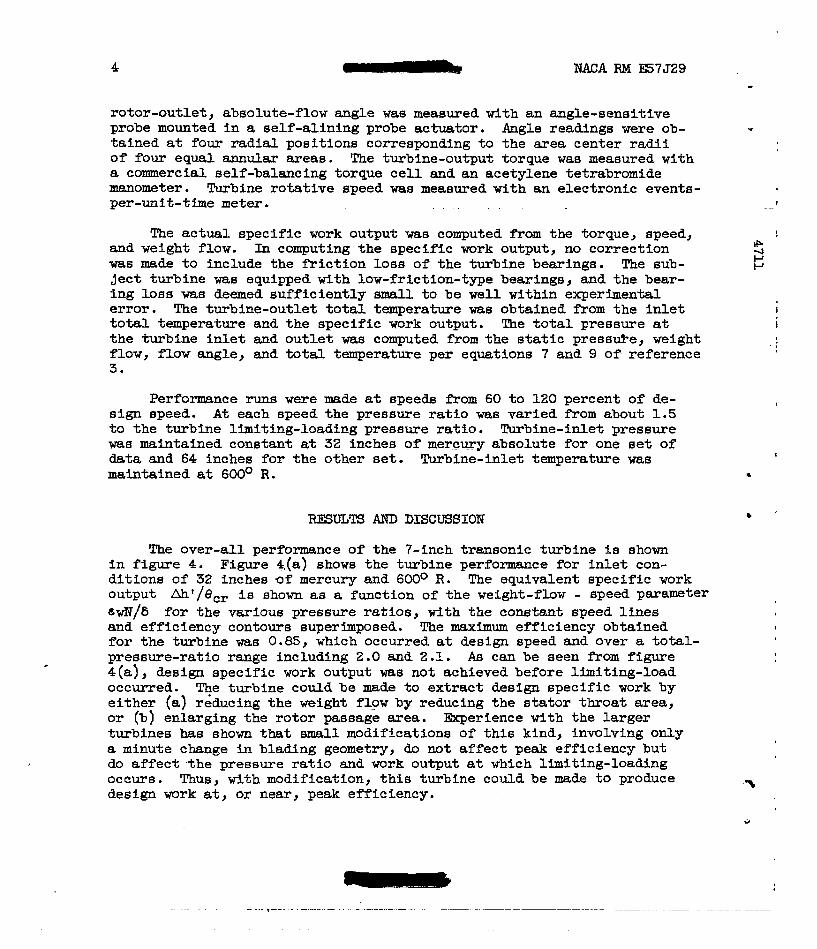
rotor-outlet, absolute-flow angle was measured with an angle-sensitive probe mounted in a self-alining probe actuator. Angle readings were ob- tained at four radial positions corresponding to the area center radii of four equal annular areas. The turbine-output torque was meaaured with a commercial self-balancing torque cell and an acetylene tetrabromide manometer. Turbine rotative speed was measured with an electronlc events- per-unit-time meter.
The actual specific work output was computed from the torque, speed, and weight flow. In computing the specific work output, no correction was made to include the fiiction loss of the turbine bearings. The sub- ject turbine was equipped with low-friction-type bearings, and the bear- ing loss was deemed sufficiently small to be well within experimental error. The turbine-outlet total temperature was obtained from the inlet total temperature and the specific work output. The total Fressure at the turbine inlet and outlet was computed from the static pressuFe, weight flow, flow angle, and total temperature per equations 7 and 9 of reference 3.
Performance runs were made at speeds from 60 to 120 percent of de- sign speed. At each speed the pressure ratio was varied from about 1.5 to the turbine limiting-loading pressure ratio. Turbine-inlet pressure was maintained constant at 32 inches of mercury absolute for one set of data and 64 inches for the other set. Turbine-inlet temperature was maintained at 60O0 R.
RESULTS AND DISCUSSION
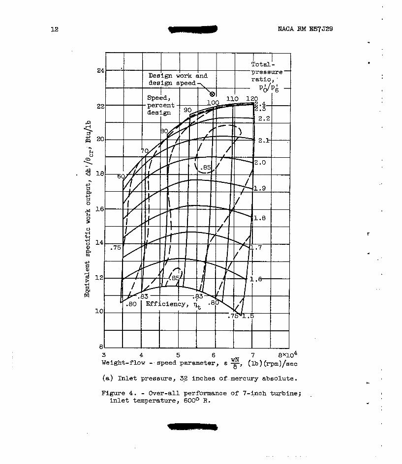
The over-all performance of the 7-inch transonic turbine is shown in figure 4. Figure 4L(a) shows the turbine performance for inlet con- ditions of 32 inches of mercury and 600° R. The equivalent specific work output &'/ecr is shown as a function of the weight-flow - speed parameter t d / S for the various pressure ratios, with the constant speed llnes and efficiency contours superhnposed. The meximum efficiency obtained for the turbine was 0.85, which occurred at design speed and over a total- pressure-ratio range including 2.0 and 2.1. As can be seen from figure 4(a), design specific work output was not achieved before limiting-load occurred. T$e turbine could be made to extract design specific work by either (a) reducing the weight flow by reducing the stator throat area, or (b) enlarging the rotor passage mea. Experience with the larger turbines has shown that mall modifications of this kind, involving only a minute change in blading geometry, do not affect peak efficiency but do affect the pressure ratio and work output at which limiting-loading occurs. Thus, with modification, this turbine could be made to produce design work at, or near, peak efficiency.
I
c 4 P P
!
c
I

ITACA RM E57J29 - 5
The performance obtained with the 14-inch turbine of reference 1 is - shown in f igure 5. F r o m a comparison of figures 4 and 5’ it can be theorized t h a t the difference in performance (2 efficiency points) is due to: (a) manufacturing tolerances or (b) Reynolds number e f f e c t , i n addi t ion to any experimental error. Manufacturing tolerence in blade fabricat ion, in t h e case of this blading and that of reference 1, was specified to give a maximum dimensional deviation of 39.005 inch from design blade contour; this deviat ion is a function of the fabrication process rather than the blade size. Thus, the dimensional tolerance as a percentage of blade chord cannot be maintained between two blade sets that are o f d i f fe ren t s izes .
The Reynolds number for the 14-inch turbine (ref. 1) could be dupli- cated with the 7-inch turbine by operating it with an inlet pressure of 64 inches of mercury absolute. The performance obtained at t h i s i n l e t pressure is shown in f igure 4 (b ) . From a comparison of figure 4(b) with f igure 4(a) , the effect of Reynolds number on over-all performance appears t o be very small for the range of Reynolds number encountered. The over- a l l performance obtained a t the two different inlet pressures i s sub- s t an t i a l ly t he same. Also, for the turbine of reference 4, no de f ln i t e trend of turbine performance as effected by inlet pressure over the range . of conditions investfgated was found. These results should not be con- strued to indicate that over-all performance I 5 generally not effected by Reynolds number, and it can be shown theoret ical ly from a simple con-
losses would be expected to decrease a6 Reynolds number i s increased. However, experimental results have ehown i n many cases that for a change of Reynolds number of t h i s magnitude, over the Reynolds number range en- countered, the effect on over-all performance is either very small or not discernible. Thus, from a consideration of the factors involved, the difference in performance between that of the 7-inch turbine and that of the 14-inch turbine is belleved to be due largely to manufacturing tol- erences. Also f e l t t o be s ignif icant are the fac ts tha t good performance can be obtained with the 7-inch turbine, which operates with transonic relative velocity through t h e rotor , and that the s fze e f fec t on perform- ance i s qui te small.
). sideration of turbulent-boundary-layer theory that aerodynamic viscous
c
t
I I
A transonic turbine wi th a 7-inch t l p diameter has been Investigated experimentally, and the performance r e su l t s are compared with those ob- tained previously with a 14-inch turbine of geometrically similar design. A peak efficiency of 0.85 was obtained with the turbine; this represents a
duct ion in peak eff ic iency that was effected by decreasing the turbine size f’rom 14 t o 7 inches was f e l t t o be s ign i f i can t ly small. The d i f fe rence in
a. decrease of 2 points from t h a t obtained with the 14-inch turbine. The re-
- efficiency, noted herein, effected by the turbine size could not be
I
6 r NACA RM E57J29 I - interpreted purely as a Reynolds number effect. Thus, this difference is believed to result largely from the inability to fabricate the smaller . I
blading ta the same percent of dimensional deviation as obtained for the larger turbine blades.
. -. - . - . . . . - . . . . - . -. . .. . . . . . . . . . - .
Lewis Flight Propulsion Laboratory National Advisory Committee for Aeronautics
Cleveland, Ohio, October 30, 1957
1. WhFtney, Warren J., Monroe, kniel E., and Wong, Robert Y. : Investigation of Wansonic Turbine Designed for Zero Diffusion of Suction-Surface Velocity. NACA RM E54F23, 1954.
.,
!
I
2. Stewrt, Warner L., Wong, Robert Y., and Evans, kvid G.: Design and ..
Experimental Investigation of Transonic Turbine with Slight Negatfve Reaction Across Rotor Hub. NACA RplI E53L29a, 1954.
3. Rohlik, Harold E., Wintucky, William T., and Scibbe, Herbert W.: I
Investigation o f a 0.6 Hub-Tip Radius-Ratio Transonic Turbine De- signed for Secondary-Flow Study. I - Design and Ekperimental Per- formance of--Standard Tur6ine. NACA RM E56Jl6, 1957. V I
4 . Schum, Harold J.: Performance Evaluation of Reduced-Chord Rotor Blad- ! ing as Applied to 573 Two-Stage Turbine. V - Effect of Inlet Pres- sure on Over-All Performance at Design Speed and Inlet Temperature I
of 700' R . NACA RM E53L16b, 1957.
&
I . . .

I
!
* NACA RM E57J29 - 7
TABLE I. - STATUR-BLADE-SECTION COORDINATES - Axis of ro ta t ion "
RL =I 0.
*.
- XI in.
- 1 .05 .10 .15 .20
.25
.30
.35 .40 .45
.50
.55
.575
.60
.65
.70
.75
.80
.85
.so
.SO6
.9L2
.925 L.00 L ,025
L .034 - .125 i. 164 -
i
0 .008
0.70
YL J
in.
1.038 .002 .038 .066 .084
.os7
.lo4
.LO8
.lo8
.lo6
.loo
.092
.088
.083
.071
.060
.044
.030
.016
.001
,000: .008 ""
""
""
""
""
""
YUY in.
0.038 .1l3 .147 .168 .179
.188
.182
.176
.IS6
.E2
.138
.I23
.115
.lo8
$ 2 d r l
is &Id
I .014 .008 ""
""
""
""
""
""
T - YLt in.
.038
.002
.om
.OS5
.074
.os0 . LOO
.lo8
.112
.112
.111
.lo7 ,105 .lo1 .093 .084 .072 ,060 .048 . o s
-
""
""
.028
.008
.002
.008 ""
"" -
SuJ YLY in. in.
1.038 0.038 .112
.174 .030 .I50 .002
.072 .189
.OS4
.196 .088
.198 .LOO
.196 .llO
.189 .116
.179 .120
.166 .121
.153 .120
.118
.113
.070 m
""
""
.064
.044 .016 .038
,008 "" "" .oos ---- e008
- YUJ in.
). 038 .114 .15E .le5 .206
-
.21a
.225
.226
.222
.216
.204
.192 ,185 .182 .168
c1 m 1 ,024 .008 -
I
I
I
I
i I
8 - MACA RM E57529
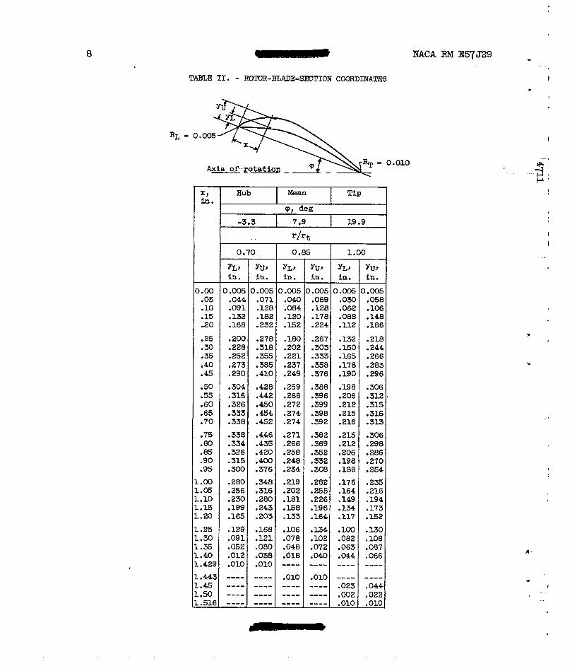
TABLE 11. - ROTOR-BLADE-SETTOM COORDINATES
= 0.010
1.00 .05 . LO .15 20
.25
.30
.35
.40 .45
.50
.55
.60 -65 .70 .75 .80 .85 .so .95
1.00
L . a 5 - .10 ..E - .20 - .25 -. 30 i .35 ..40 L .429 - .443 -. 45 -. 50 . .516
0.70 1.00 0.85
YLI Yu, YLt YU, YLt YU, in. in. in. in. in. in.
0.005 0.005
.186 .112 .224 .E2 .232 .16%
.lo6 .062 .128 .084 -128 .091
0.005 0.005 0.005 0.005
.200 .278 .180 .267 .E52 .244 .l50 .303 .202 .3lB .228 .218
.296 .190 .376 .249 .410 .290
.283 .178 .358 .237 .385 .273
.266 .165 .333 .221 .355 .252
.304 .428 .259 .388 .198 .306
.326 .e0 .272 .399 .212 .3l5 ,333 .454 .274 .398 .215 .316 .338 .3l3 .216 .392 .274 .452
.338 .446 .271 .382 .2L5 .306
.334 .435 .266 .369 .212 .298 ,326 .420 .258 .352
.254 .188 ,308 .234 .376 .300 .270 .198 .332 .248 .400 .3L5
.286 .206
.OM
.14a .088 .17a ,120 .m2 .132
.os8 .om .om .om .on
-316 -312. -206 -396 -266 -442
.2ao .235 .176 ,282 a s .348
.256
.E2 .117 .164 .133 .203 .165
.I73 .I34 .196 ,158 .243 .199
.194 .149 .226 .181 .280 .230
.216 ,164 .255 .202 .316
.129 ,168 .lo6 .134 .lo0 .lo8 .082 . lo2 ,078 .I21 .091 .I30
"" "" "" ---- .OlO .010 .066 .044 .040 .018 .038 .012 .087 .063 .072 .048 .080 -052
"" "" .010 -" - "- -e-- --_- ---_ _ _ _ _ .023 -044 -"e
.010 .010 -022 .m2 "" "" ""
"" "" "" ""
* - .
.
I
c
b
.* .
a
.
NACA RM E5'j'm 9
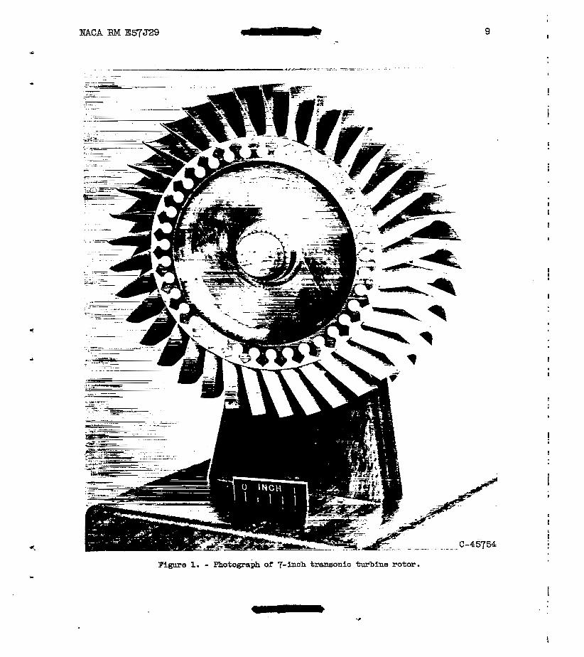
Figure 1. - Photograph of 7-inch transonic turbine rotor.
I
#
I
!
i
I
I
I
!
'54
t

. . . . . .
I ?
I . ..
* 1
. . . . . ..
bTACA RM E57529 11
I
I
I
t
... 3,:. .. L f m v
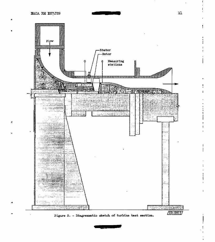
Figure 3. - Diagramtic sketch of turbine t e s t section.
12 NACA RM E57J29
3 4 5 6 7 8 X 1 0 4 Weight-flow - . speed parameter, e ( lb ) (q,)/,ec
(a) In le t p ressure , 32 inches ofmercury absolute .
WN
Figure 4. - Over-all performance of 7-inch turbine; Fnlet temperature, 600° R.

ESACA RM E57329
A
. .
24
22
20
18
16
14
12
10
t I Design work and I Total- I I I
3 4 5 6 7 x10⁴
Weight-flow - speed parameter, = E", WN (Ib) bpm) /set 6
(b) Inlet pressure, 64 inches of mercury absolute.
Figure 4. - Concluded. Over-all performance of 7-inch turbine; inlet temperature, 600° R .
I
I
I
I

14
. .
NACA RM E57J29
24
22
3 3
b '=z
8 20
SI 18
*
i 0
24 16 * 8 0
5 14
%
- 2 1 2 3 w
10
8 6 8 10 12 14 1 6 X 1 0 4
Weight-flow - speed parameter, t -> (lb)(rpm)/eec WN 8
Figure 5. - Over-all performance of 14-inch turbine.
I
"."
I
t - 1