Research Limited PM7000 Research Limited Hook … PM7000 Research Limited A successful hook-up...
14
Ranger PM7000 Research Limited Hook-up Checklist for the Ranger PM7000 (EU) Step 1. Establish type of installation (e.g. no. of phases). Step 2. Establish type of transducers (PTs, CTs etc.). Step 3. Choose one of the ten following hook-up options: 1) 3-Phase 4-Wire Wye 2) 3-Phase 4-Wire Delta 3) Full 3-Phase 3-Wire Delta (3 element for all Ph-Ph) 4) 3-Phase 3-Wire Ungrounded (with Equipment Gnd) 5) 3-Phase 3-Wire Ungrounded 6) 3-Phase 2.5-Element Wye 7) 3-Phase 1-Element Wye 8) Single Split Phase 9) Single Phase 10) Uncommitted. Those in bold are used most frequently. Step 4. Configure instrument for relevant hook-up. Step 5. Verify physical connections along with instrument LED and outputs ( ). Step 6. If required, refer to Phase Angle Summary ( ). Step 7. If vectors or LED configurations do not match what is expected or you see the “Suspect Hook-Up” message, refer to possible explanations and action to be taken ( ). PMScreen vector see pp. 1-10 of these notes p. 11 pp. 12-13 Research Limited
Transcript of Research Limited PM7000 Research Limited Hook … PM7000 Research Limited A successful hook-up...

RangerPM7000
Research Limited
Hook-up Checklistfor the Ranger PM7000 (EU)
Step 1. Establish type of installation (e.g. no. of phases).
Step 2. Establish type of transducers (PTs, CTs etc.).
Step 3. Choose one of the ten following hook-up options:
1) 3-Phase 4-Wire Wye2) 3-Phase 4-Wire Delta3) Full 3-Phase 3-Wire Delta (3 element for all Ph-Ph)4) 3-Phase 3-Wire Ungrounded (with Equipment Gnd)5) 3-Phase 3-Wire Ungrounded6) 3-Phase 2.5-Element Wye7) 3-Phase 1-Element Wye8) Single Split Phase9) Single Phase10) Uncommitted.Those in bold are used most frequently.
Step 4. Configure instrument for relevant hook-up.
Step 5. Verify physical connectionsalong with instrument LED and
outputs ( ).
Step 6. If required, refer to Phase Angle Summary ( ).
Step 7. If vectors or LED configurations do not match what is expected or you see the“Suspect Hook-Up” message, refer to possible explanations and action to be taken ( ).
PMScreen vector see pp. 1-10 of these notes
p. 11
pp. 12-13
Research Limited

RangerPM7000
Research Limited
A successful hook-up (based on physical connections and corresponding instrument configuration) is demonstrated via: a) sequentially flashing green LEDs on the top of the instrument b) vector outputs as seen on PMScreen.
Hook-up as displayed on PMScreen
3-Phase 4-Wire Wye
I1I1
I2I2
I3I3
V1 V1
V2V2
V3V3
Slightly leading PF
I1I1
I2I2
I3I3
V1 V1
V2V2
V3V3
I1I1
I2I2
I3I3
V1 V1
V2V2
V3V3
Unity Power Factor (PF)
an
bn
cn
a
c
b
Volts Amps
Connections Rogowski Coil 3Ø 4w Wye
Connections are made using: 4 Rogowski Coils, 5 Voltage Leadswith the common Neutral connected via 3 link leads (blue or white).
1
Slightly lagging PF
an
bn
cnVolts Amps
Connections Rogowski Coil 3Ø 4w Wye
c
ab
an
bn
cnAmpsVolts
Connections Rogowski Coil 3Ø 4w Wye
ac
b
Something not looking right?
Hook-up 1/10
Screenshot from PMScreenPM 7000 LEDs
Screenshot from PMScreen
See pp. 12 & 13 for possible solutions.

RangerPM7000
Research Limited
3-Phase 4-Wire Delta
Hook-up 2/10
I1I1
I2I2
I3I3
V1 V1
V2V2
V3V3
I1I1
I2I2
I3I3
V1 V1
V2V2
V3V3
I1I1
I2I2
I3I3
V1 V1
V2V2
V3V3
Connections are made using: 3 Rogowski Coils, 5 Voltage Leadswith the common Neutral connected via 3 link leads (blue or white).
2
Option: Although not essential it maybe useful to connect up the 4th Rogowski coil (blue) as the current could flow along the Neutral.
Something not looking right?
See pp. 12 & 13 for possible solutions.
Slightly leading PF
Slightly lagging PF
Unity Power Factor (PF)
ac
b
Volts Amps
Connections Rogowski Coil 3Ø 4w Delta
c
a
b
Volts Amps
Connections Rogowski Coil 3Ø 4w Delta
a
c
b
AmpsVolts
Connections Rogowski Coil 3Ø 4w Delta
Screenshot from PMScreenPM 7000 LEDs
Screenshot from PMScreen
A successful hook-up (based on physical connections and corresponding instrument configuration) is demonstrated via: a) sequentially flashing green LEDs on the top of the instrument b) vector outputs as seen on PMScreen.
Hook-up as displayed on PMScreen
an
bn
cn
an
bn
cn
an
bn
cn
RangerPM7000
Research Limited
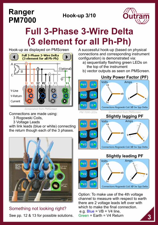
Full 3-Phase 3-Wire Delta (3 element for all Ph-Ph)
Hook-up 3/10
I1I1
I2I2
I3I3
V1 V1
V2V2
V3V3
Unity Power Factor (PF)
ab
bc
ca
a
c
b
Volts Amps
Connections Rogowski Coil 3Ø 3w 3pp Delta
Connections are made using: 3 Rogowski Coils, 3 Voltage Leadswith link leads (blue or white) connectingthe return though each of the 3 phases.
I1I1
I2I2
I3I3
V1 V1
V2V2
V3V3
Slightly lagging PF
I1I1
I2I2
I3I3
V1 V1
V2V2
V3V3
Slightly leading PF
Volts Amps
Connections Rogowski Coil 3Ø 3w 3pp Delta
ab
bc
ca c
b
a
a
c
b
AmpsVolts
ab
bc
ca
Connections Rogowski Coil 3Ø 3w 3pp Delta
3
Option: To make use of the 4th voltage channel to measure with respect to earth there are 2 voltage leads left over with which to make the final connection. e.g. = VB = V4 line,
= Earth = V4 ReturnBlue
Green
Something not looking right?
See pp. 12 & 13 for possible solutions.
PM 7000 LEDs Screenshot from PMScreenScreenshot from PMScreen
A successful hook-up (based on physical connections and corresponding instrument configuration) is demonstrated via: a) sequentially flashing green LEDs on the top of the instrument b) vector outputs as seen on PMScreen.
Hook-up as displayed on PMScreen
RangerPM7000
Research Limited
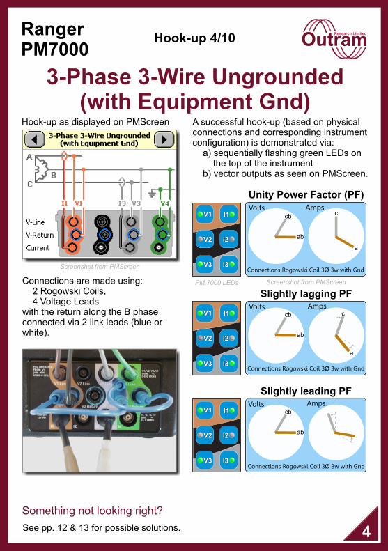
3-Phase 3-Wire Ungrounded (with Equipment Gnd)
Hook-up 4/10
Connections are made using: 2 Rogowski Coils, 4 Voltage Leadswith the return along the B phase connected via 2 link leads (blue or white).
4
Slightly lagging PF
c
a
Volts Amps
ab
cb
Connections Rogowski Coil 3Ø 3w with Gnd
Slightly leading PF
a
cAmpsVolts
ab
cb
Connections Rogowski Coil 3Ø 3w with Gnd
I1I1
I2I2
I3I3
V1 V1
V2V2
V3V3
I1I1
I2I2
I3I3
V1 V1
V2V2
V3V3
Something not looking right?
See pp. 12 & 13 for possible solutions.
PM 7000 LEDs
Unity Power Factor (PF)
ab
cb
a
cVolts Amps
Connections Rogowski Coil 3Ø 3w with Gnd
Screenshot from PMScreen
Screenshot from PMScreen
A successful hook-up (based on physical connections and corresponding instrument configuration) is demonstrated via: a) sequentially flashing green LEDs on the top of the instrument b) vector outputs as seen on PMScreen.
Hook-up as displayed on PMScreen
I1I1
I2I2
I3I3
V1 V1
V2V2
V3V3

RangerPM7000
Research Limited
3-Phase 3-Wire Ungrounded
Hook-up 5/10
Unity Power Factor (PF)
ab
cb
a
cVolts Amps
Connections Rogowski Coil 3Ø 3w Delta
Connections are made using: 2 Rogowski Coils, 3 Voltage Leadswith the return along the B phase connected via 1 link lead (blue or white). No Earth.
5
Slightly lagging PF
c
a
Volts Amps
ab
cb
Connections Rogowski Coil 3Ø 3w Delta
Slightly leading PF
a
cAmpsVolts
ab
cb
Connections Rogowski Coil 3Ø 3w Delta
I1I1
I2I2
I3I3
V1 V1
V2V2
V3V3
I1I1
I2I2
I3I3
V1 V1
V2V2
V3V3
I1I1
I2I2
I3I3
V1 V1
V2V2
V3V3
Something not looking right?
See pp. 12 & 13 for possible solutions.
Screenshot from PMScreenPM 7000 LEDs
Screenshot from PMScreen
A successful hook-up (based on physical connections and corresponding instrument configuration) is demonstrated via: a) sequentially flashing green LEDs on the top of the instrument b) vector outputs as seen on PMScreen.
Hook-up as displayed on PMScreen
RangerPM7000
Research Limited
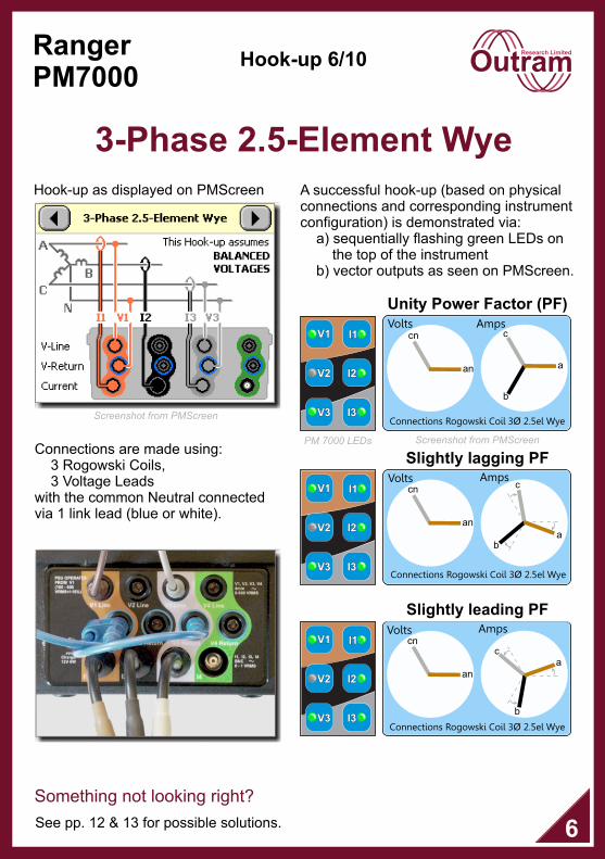
3-Phase 2.5-Element Wye
Hook-up 6/10
Connections are made using: 3 Rogowski Coils, 3 Voltage Leadswith the common Neutral connected via 1 link lead (blue or white).
6
Unity Power Factor (PF)
an
cnVolts Amps
Connections Rogowski Coil 3Ø 2.5el Wye
a
c
b
I1I1
I2I2
I3I3
V1 V1
V2V2
V3V3
I1I1
I2I2
I3I3
V1 V1
V2V2
V3V3
I1I1
I2I2
I3I3
V1 V1
V2V2
V3V3
Slightly lagging PFVolts Amps
Connections Rogowski Coil 3Ø 2.5el Wye
c
ab
an
cn
Slightly leading PFAmpsVolts
Connections Rogowski Coil 3Ø 2.5el Wye
ac
b
an
cn
Something not looking right?
See pp. 12 & 13 for possible solutions.
Screenshot from PMScreenPM 7000 LEDs
Screenshot from PMScreen
A successful hook-up (based on physical connections and corresponding instrument configuration) is demonstrated via: a) sequentially flashing green LEDs on the top of the instrument b) vector outputs as seen on PMScreen.
Hook-up as displayed on PMScreen
RangerPM7000
Research Limited
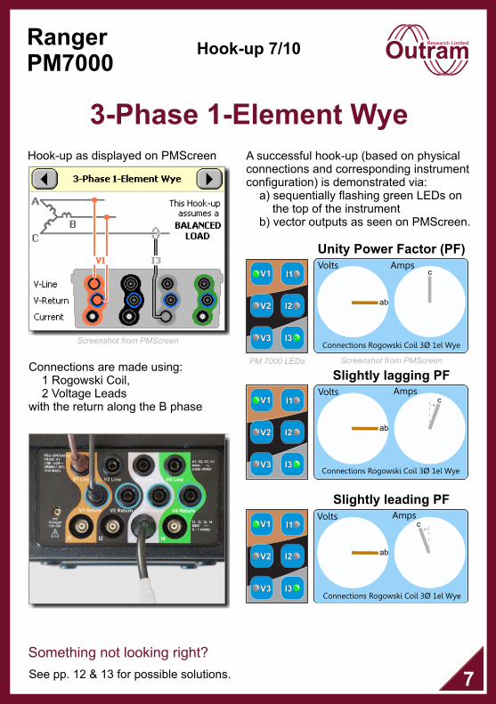
3-Phase 1-Element Wye
Hook-up 7/10
Unity Power Factor (PF)
ab
cVolts Amps
Connections Rogowski Coil 3Ø 1el Wye
Connections are made using: 1 Rogowski Coil, 2 Voltage Leadswith the return along the B phase
7
Slightly leading PF
cAmpsVolts
ab
Connections Rogowski Coil 3Ø 1el Wye
Slightly lagging PF
cVolts Amps
ab
Connections Rogowski Coil 3Ø 1el Wye
I1I1
I2I2
I3I3
V1 V1
V2V2
V3V3
I1I1
I2I2
I3I3
V1 V1
V2V2
V3V3
I1I1
I2I2
I3I3
V1 V1
V2V2
V3V3
See pp. 12 & 13 for possible solutions.
Something not looking right?
Screenshot from PMScreenPM 7000 LEDs
Screenshot from PMScreen
A successful hook-up (based on physical connections and corresponding instrument configuration) is demonstrated via: a) sequentially flashing green LEDs on the top of the instrument b) vector outputs as seen on PMScreen.
Hook-up as displayed on PMScreen
RangerPM7000
Research Limited
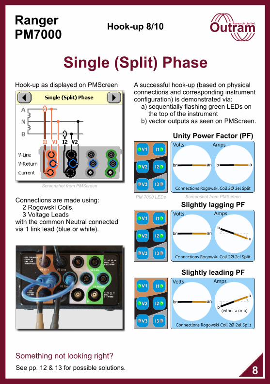
Single (Split) Phase
Hook-up 8/10
Slightly lagging PF
Unity Power Factor (PF)
Connections are made using: 2 Rogowski Coils, 3 Voltage Leadswith the common Neutral connected via 1 link lead (blue or white).
8
Slightly leading PF
Volts Amps
Connections Rogowski Coil 2Ø 2el Split
anbn ab
AmpsVolts
Connections Rogowski Coil 2Ø 2el Split
anbn
a
b(either a or b)
I1I1
I2I2
I3I3
V1 V1
V2V2
V3V3
Volts Amps
Connections Rogowski Coil 2Ø 2el Split
an
a
b
bn
I1I1
I2I2
I3I3
V1 V1
V2V2
V3V3
I1I1
I2I2
I3I3
V1 V1
V2V2
V3V3
See pp. 12 & 13 for possible solutions.
Something not looking right?
Screenshot from PMScreenPM 7000 LEDs
Screenshot from PMScreen
A successful hook-up (based on physical connections and corresponding instrument configuration) is demonstrated via: a) sequentially flashing green LEDs on the top of the instrument b) vector outputs as seen on PMScreen.
Hook-up as displayed on PMScreen

RangerPM7000
Research Limited
Single Phase
Hook-up 9/10
Slightly lagging PF
Unity Power Factor (PF)
Connections are made using: 1 Rogowski Coil, 3 Voltage Leadswith the common Neutral connected via 1 link lead (blue or white).
9
Slightly leading PF
Volts Amps
an a
Connections Rogowski Coil Single
Volts Amps
an
a
Connections Rogowski Coil Single
AmpsVolts
Connections Rogowski Coil Single
an
a
I1I1
I2I2
I3I3
V1 V1
V2V2
V3V3
I1I1
I2I2
I3I3
V1 V1
V2V2
V3V3
I1I1
I2I2
I3I3
V1 V1
V2V2
V3V3
See pp. 12 & 13 for possible solutions.
Something not looking right?
Screenshot from PMScreenPM 7000 LEDs
Screenshot from PMScreen
A successful hook-up (based on physical connections and corresponding instrument configuration) is demonstrated via: a) sequentially flashing green LEDs on the top of the instrument b) vector outputs as seen on PMScreen.
Hook-up as displayed on PMScreen

RangerPM7000
Research Limited
Uncommitted
Hook-up 10/10
Slightly lagging PF
Unity Power Factor (PF)
10
Slightly leading PF
I1I1
I2I2
I3I3
V1 V1
V2V2
V3V3
I1I1
I2I2
I3I3
V1 V1
V2V2
V3V3
You can use whichever connectionsare required.
I1I1
I2I2
I3I3
V1 V1
V2V2
V3V3
Volts Amps
Connections Rogowski Coil Uncommitted
? ?
Volts Amps
Connections Rogowski Coil Uncommitted
? ?
AmpsVolts
Connections Rogowski Coil Uncommitted
? ?
Screenshot from PMScreenPM 7000 LEDs
Screenshot from PMScreen
A successful hook-up (based on physical connections and corresponding instrument configuration) is demonstrated via: a) sequentially flashing green LEDs on the top of the instrument b) vector outputs as seen on PMScreen.
Hook-up as displayed on PMScreen

RangerPM7000
Research Limited
Phase Angle Summary
It is possible at this point to reverse the current phases by clicking . This is recommended for correction only when manual reversal is not possible.
11
Phase angle wrt expected
Hook-Up
LED on top of
instrument
0 ± 10° Good Green
180 ± 10° Reversed Red
All else Suspect Orange
Expected phase angles are with respect to the reference vector of ChV1
Voltage Tolerances
Phase angle wrt expected
Hook-Up
LED on top of
instrument
0 ± 45° Good Green
180 ± 45° Reversed Red
All else Suspect Orange
Current Tolerances
If “Suspect Hook-Up” shows, click on the PMScreen vector diagram where it will show the hook-up that the instrument is anticipating. Click on for specific information and advice.
Hook-Up Description V1 V2 V3 I1 I2 I3
1 3-Phase 4-Wire Wye 0° 240° 120° 0° 240° 120°
2 3-Phase 4-Wire Delta 0° -90° 180° 30° -90° 150°
3Full 3-Phase 3-Wire Delta (3 element for all Ph-Ph) 0° 240° 120° -30° 210° 90°
43-Phase 3-Wire Ungrounded (with Equipment Gnd) 0° 60° -30° 90°
5 3-Phase 3-Wire Ungrounded 0° 60° -30° 90°
6 3-Phase 2.5-Element Wye 0° 120° 0° 240° 120°
7 3-Phase 1-Element Wye 0° 90°
8 Single Split Phase 0° 180° 0° 180°
9 Single Phase 0° 0°
10 Uncommitted ? ? ? ? ? ?
RangerPM7000
Research Limited
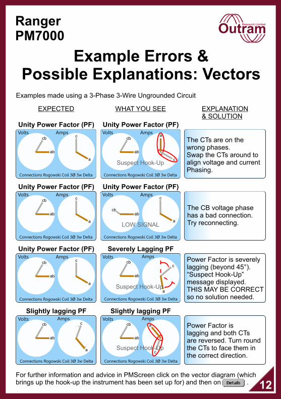
Example Errors & Possible Explanations: Vectors
Examples made using a 3-Phase 3-Wire Ungrounded Circuit
EXPECTED WHAT YOU SEE EXPLANATION & SOLUTION
Unity Power Factor (PF)
ab
cb
a
cVolts Amps
Connections Rogowski Coil 3Ø 3w Delta
Unity Power Factor (PF)
Slightly lagging PF
c
a
Volts Amps
ab
cb
Connections Rogowski Coil 3Ø 3w Delta
Slightly lagging PF
c
a
Volts Amps
ab
cb
Connections Rogowski Coil 3Ø 3w Delta
Suspect Hook-Up
Severely Lagging PF
Unity Power Factor (PF)
The CTs are on thewrong phases.Swap the CTs around to align voltage and current Phasing.
ab
cb
a
cVolts Amps
Connections Rogowski Coil 3Ø 3w Delta
Unity Power Factor (PF)
Unity Power Factor (PF)
ab
cb
a
cVolts Amps
Connections Rogowski Coil 3Ø 3w Delta
ab
cba
c
Volts Amps
Connections Rogowski Coil 3Ø 3w Delta
Suspect Hook-Up
c
a
Volts Amps
ab
cb
Connections Rogowski Coil 3Ø 3w Delta
Suspect Hook-Up
The CB voltage phase has a bad connection. Try reconnecting.
Power Factor is severelylagging (beyond 45°). “Suspect Hook-Up”message displayed. THIS MAY BE CORRECTso no solution needed.
Power Factor is lagging and both CTs are reversed. Turn roundthe CTs to face them in the correct direction.
12
cbab
Volts Amps
Connections Rogowski Coil 3Ø 3w Delta
c
aLOW SIGNAL
For further information and advice in PMScreen click on the vector diagram (which brings up the hook-up the instrument has been set up for) and then on .

RangerPM7000
Research Limited
Example Errors & Possible Explanations: LEDs
13
Examples made using a 3-Phase 3-Wire Ungrounded Circuit
EXPECTED WHAT YOU SEE EXPLANATION & SOLUTION
I1I1
I2I2
I3I3
V1 V1
V2V2
V3V3
No signal received by CB phase voltage lead. Check connection.
Current phase A is probably reversed. Try changing it round.
Current phases A & C may be swapped over OR possibly have very bad Power Factor due to excessive lagging current. In the latter case the phases may be correct.If necessary try swapping CTs over. Refer to Vector diagrams if unsure.
For more information and advice as well as details of further products in our range please visit our website at www.outramresearch.co.uk
I1I1
I2I2
I3I3
V1 V1
V2V2
V3V3
I1I1
I2I2
I3I3
V1 V1
V2V2
V3V3
I1I1
I2I2
I3I3
V1 V1
V2V2
V3V3