RESEARCH. DEVELOPMENT ENGINEERING · ad-a250 104 chemical research. development 5 engineering...
135
AD-A2 5 0 104 CHEMICAL RESEARCH. DEVELOPMENT 5 ENGINEERING CENTER CRDEC-SP-046 SPECIALTY SYMPOSIUM - PARTICLE PRODUCTION, CHARACTERIZATION, AND APPLICATIONS DTIC Madhav B. Ranade SE-ECTE PARTICLETECHNOLOGY, INC. MAYO . 1992 College Park, MD 20742 V I W Erica R. Petersen RESEARCH DIRECTORATE March 1992 Approved for public release; distribution Is unlimited. U.S. ARMY ARMAMENT MUNmONS CHEMICAL COMMAND Aberdeen Provng Gmumd. Maylamd 21MO4423 92-12261 92 5 05 . 0*J _ lllH~lll~tIltMll
Transcript of RESEARCH. DEVELOPMENT ENGINEERING · ad-a250 104 chemical research. development 5 engineering...

AD-A25 0 104
CHEMICAL
RESEARCH.DEVELOPMENT 5ENGINEERINGCENTER
CRDEC-SP-046
SPECIALTY SYMPOSIUM - PARTICLE PRODUCTION,CHARACTERIZATION, AND APPLICATIONS
DTIC Madhav B. Ranade
SE-ECTE PARTICLETECHNOLOGY, INC.MAYO .1992 College Park, MD 20742
V I W Erica R. Petersen
RESEARCH DIRECTORATE
March 1992
Approved for public release; distribution Is unlimited.
U.S. ARMYARMAMENTMUNmONSCHEMICAL COMMAND
Aberdeen Provng Gmumd. Maylamd 21MO4423
92-1226192 5 05 . 0 *J _ lllH~lll~tIltMllll
Disclaimer
The findings in this report are not to be construed as anofficial Department of the Army position unless so designated byother authorizing documents.

Form ApprovedREPORT DOCUMENTATION PAGE OMB No 0704-0188
VVJI '~ oO' -*. .. 1n, -tcrmant- 'S i , i~ walp Der -so - .'~ n" .- :~' eal: - STn oath %our'.%gathe..,q anc mnaintaning the data needed, and comole.nq aird e.'"ewC,n I '- Cue"q'n ot r,'M1"ra on Spno comm.nt rpoarc.r; Tr, r, o'en estmate Cf anv ol her asoect of t,Cowio n o .* f 3
tntOrma! ion. nouding suggestons for reducing thj$ Oultser -c "/a r~O eaaa~ane,% 5er..ce5. i,-.oa 1 -1r -4 " -C O ' a nd ara eDojs . 1215 Jefferson
Da.,% Mghi .Suate 1204 Arngton. VA 22202 n4302d. To th'! 0fll?. it Manaaement ano ua;et. Paofor Reo.I. 1o, P.re1: (07C-4-0 8b) "aa .rncton DC 20503
1. AGENCY USE ONLY (Leave blank) 2. REPORT DATE 3. REPORT TYPE AND DATES COVERED
1992 March Final, 88 Apr - 88 Oct4. TITLE AND SUBTITLE 5. FUNDING NUMBERS
Specialty Symposium - Particle Production, PR-88266Characterization, and Applications (Delivery
6. AUTHOR(S) Order No. 0977)6. AUTHOR(S)
Ranade, Madhav B. (Particle Technology,Inc.), and Petersen, Erica R. (CRDEC)
7. PERFORMING ORGANIZATION NAME(S) AND ADDRESS(ES) 8. PERFOR.!,NG ORGANIZATION
REPORT NUMBER
Particle Technology, Inc.Building 335 CRDEC-SP- 046Technology Advancement ProgramCollege Park, MD 20742
9. SPONSORING /MONITORING AGENCY NAME(S) AND ADDRESS(ES) 10. SPONSORING/ MONITORINGAGENCY REPORT NUMBER
CDR, CRDEC, ATTN: SMCCR-RSP-B,APG, MD 21010-5423
11. SUPPLEMENTARY NOTES
Task was performed under a Scientific Services Agreement issued byBattelle, Research Triangle Park Office, 200 Park Drive, P.O. Box12297, Research Triangle Park, NC 27709.
12a. DISTRIBUTION / AVAILABIUTY STATEMENT 12b. DISTRIBUTION CODE
Approved for public release; distribution isunlimited.
13. ABSTRACT (Maximum 200 words)
A Specialty Symposium was held at Hunt Valley Marriott near Baltimore,MD on May 16-18, 1988. Participants were invited from industry,academic institutions, and government agencies engaged in particletechnology-related work. A total of 20 presentations were madeon several topics which included particle production, aerosolcharacterization, and applications. The final report containssummaries of the presentations and discussions. Recommendations forfuture conferences with joint participation by industry and governmentare made to facilitate technology transfer from various disciplines.
14. SUBJECT TERMS 15. NUMBER OF PAGES
Fine particles Powders Size measurement 133Particle technology Aerosols 16. PRICE CODE
17. SECURITY CLASSIFICATION 16. SECURITY CLASSIFICATION 19. SECURITY CLASSIFICATION 20. LIMITATION OF ABSTRACT
OF REPORT OF THIS PAGE OF ABSTRACT
UNCLASSIFIED UNCLASSIFIED UNCLASSIFIED ULNSN 75401-280-5500 Standard Form 298 (Rev 2-89)
P-ir','fld rw ANI Sid 134-18

Blank
PREFACE
The work described in this report was authorized underProject No. 88266 (Delivery Order No. 0977). This work wasstarted in April 1988 and completed in October 1988.
The use of trade names or manufacturers' names in thisreport does not constitute an official endorsement of anycommercial products. This report may not be cited for purposesof advertisement.
Reproduction of this document in whole or in part isprohibited except with permission of the Commander, U.S. ArmyChemical Research, Development and Engineering Center, ATTN:SMCCR-SPS-T, Aberdeen Proving Ground, MD 21010-5423. However,the Defense Technical Information Center and the NationalTechnical Information Service are authorized to reproduce thedocument for U.S. Government purposes.
This report has been approved for release to the public.
Acknowledaments
Valeric Ford (Particle Technology, Inc.) providedsecretarial support and was responsible for a smooth runningSymposium Program.
Aeoession For
NTIS GRA&IDTIC TAB 0Unannounced
Justifiohtio
Distribution/
AvaplabilitY CodesA vaf iij B/o rlot Speolal
3q ~

Blank
4

CONTENTS
Page
INTRODUCTION ............................................... 7
SECTION I. SPECIAL TOPIC - PLENARY LECTURE .............. 9
Benjamin Y.H. Liu - "Advances in Aerosol Filtration ... 11
SECTION II. PARTICLE PRODUCTION AND DISSEMINATION ........ 27
David T. Shaw - "Particle Generation in AerosolReactors" ........................................... 29
Sotiris E. Pratsinis - "Material Synthesis by AerosolProcesses" ........................................... 31
E.R. Riley - "An Overview of Particle Generation forObscuration" ........................................... 35
R.E. Partch - "Chemical Reactions in Aerosols - A NewTechnique for Preparation of Colloids of Narrow-SizeDistribution" ......................................... 39
V.B. Menon, M.E. Mullins, and M.B. Ranade - "ColloidalProcesses for Particle Production" ................... 43
Paul Schoen - "Lipid Tubule Microstructures:Formation, Metallization, and Applications" ......... 59
M.B. (Arun) Ranade - "Dispersion and Dissemination ofDry Powders" ........................................... 61
SECTION III. SAMPLING AND MEASUREMENT OF AIRBORNEPARTICLES .................................... 65
James W. Gentry - "Aerosol Sampling and Measurement" 67A.R. McFarland, W.D. Turner, C.A. Ortiz, N.K. Anand,
M.G. Glass, R.E. DeOtte, Jr., S. Somasundaram, andD.L. O'Neal - "Aerosol Sampling Studies" ............ 71
George Mulholland, Nelson Bryner, and RaymondMountain - "Optical Properties of SmokeAgglomerates" . ...................................... 81
George M. Thomson - "Aerosol Mass ConcentrationMeasurements by X-Ray Fluorescence" .................. 85
Janon Embury - "Inversion of Aerosol SpectralTransmittance to Determine Size Distribution ofConcentration" . ...................................... 89
SECTION IV. PARTICLE CHARACTERIZATION AND APPLICATIONS OFPARTICLE TECHNOLOGY ........................ 103
J.K. Beddow - "An Exercise in ParticleCharacterization" .................................... 105
Thomas R. Lettieri - "Particle-Sizing ReferenceMaterials from the National Bureau of Standards" .... ill
5
Terry Allen and Reg Davies - "Particle Size Measurementin Powder Technology" ................................ 119
Marek A. Sitarski - "Predictions of a Fate of a SmallHeterogeneous Droplet Based on an Absorption Patternof the Incident Electromagnetic Radiation" ........... 123
D.S. Ensor and R.P. Donovan - "MicrocontaminationControl: Achieving and Measuring Ultra-CleanConditions" ......................................... 125
Norman Plaks - "Particulate Control Research andDevelopment at EPA" ................................. 127
CONCLUSIONS AND RECOMMENDATIONS ............................ 128
APPENDIX - SYMPOSIUM PROGRAM ............................... 131
6
SPECIALTY SYMPOSIUM - PARTICLE PRODUCTION,CHARACTERIZATION, AND APPLICATIONS
INTRODUCTION
In recent years, the science and technology of fine particleshas become a crucial factor in many fields, both in government andin industry. Fine particles differ from bulk materials,exhibiting properties that make them critical components in manyproducts and processes. These differences necessitate specializedapproaches to research and development efforts associated withfine particles.
Applications of fine particles span a range covering ceramicsand composites processing, pigment and pharmaceutical components,military smokes and obscurants, military protection systems, andpowder metallurgy. Subjects of concern to these fields includeparticle generation, control of morphology and homogeneity,filtering, measurement and characterization, particle capture,handling and contamination control.
Because of the breadth of concerns about fine particles theinformation available on the subject is scattered throughout theliterature of numerous fields. Treatment of particle technologyas a significant discipline independent of application is arelatively new effort, requiring expertise in numerous fields ofapplications as well as in the particle-specific technologies.In many instances the concerns of Department of Defense scientistsand contractors are unique and are not well addressed by thegeneral scientific community. This fact led us to theorganization of a meeting of particle specialists from a broadspectrum of applications specifically suited to addressing some ofthe current military concerns.
A major goal of the Symposium was to identify overlap oftechnical issues in defense and other communities. For exampleparticle removal from air or gases is of importance for chemicaldefense, microcontamination control, and air pollution control andthe basic mechanisms of filtration are common to all. Otherexamples include powder flow and dispersion problems in industryas well as in developing smoke munitions.
The technical areas we were able to cover in the rather shorttime for preparation of the Program and for the Symposium were ofareas of direct interest to the Army. The Sections were arrangedto permit natural flow of topics from particle production, theircharacterization, and uses and applications in other technologicalareas.
In the next Section the papers are arranged according to themajor topical areas and not necessarily in the order of theirpresentation. The Symposium Program is included in the Appendix.The details and the length of the written papers were notuniformly specified to facilitate publication in a timely mannerwithout causing a burden to the participants.
7

Blank

SECTION 1: SPECIAL TOPIC -PLENARY LECTURE
9

Blank
10
ADVANCES IN AEROSOL FILTRATION
Benjamin Y.H. LiuProfessor and Director, Particle Technology Laboratory,
Mechanical Engineering Department, University of MinnesotaMinneapolis, MN 55455
Introduction
Fibrous and membrane filters are widely used for the removal ofparticulate contaminants from air or gas streams. As such. they areimportant in various applicationa requiring purfied streams for health orequipment protection or for manufacturing processes.
Advances in filtration technology in recent years have proceeded alongtwo fronts. On the one hand, there are significant advances in the theory ofair and gas filtration. The theoretical understanding of filtration mechanismsand the theory of fibrous and membrane filters have progressed to thepoint where many filters can now be designed theoretically. Further, thereis a concomitant advance in manufacturing technology. Filter media andfiltration devices with varying characteristics can now be manufactured.often with high and consistent quality. As a result, numerous filtrationproducts are available commercially and they can be used to meet thediverse filtration needs of industry.
The purpose of this paper is to provide an overview of air and gasfiltration with the major emphasis on the mechanism and the theory offiltration. The influence of filter fiber or pore size, filter structure and otherimportant filtration parameters on filter performance will be discussed. Themethod of tests of air and gas filters will then be described along with theperformance characteristics of some commercially available filters.
TVMes of Filters and Their Physcal Characteristics
Fibrous and membrane filters are both used for high purity air or gasfiltration. Fibrous filters are more commonly used where a large volume ofair or gas must be processed. Membrane filters, on the other hand, becauseof their higher cost and absolute particle retention characteristics, are moreoften used where the purity requirement is high and the volume of gas to beprocessed is comparatively small. Major application of fibrous filters includeventilation and clean room air flitration and industrial air or gas cleaning forpollution and contamination control and product recovery. Majorapplications of membrane filters include process gas and liquid filtration inthe pharmaceutical, semiconductor and biomedical industries and theirapplications as sampling filter media for analytical purposes.
Fibrous filters are made of glass or polymer fibers. The fiber diametermay range from as small as 0. 1 to tens of micrometers. They are usuallymade through a wet, paper making process in which the fibers are firstmade into a wet slurry and formed into mats which are subsequentlydewatered and pressed. In the case of fibrous filters made of polymericfibers, the fibers may be spun and formed into the final filter sheet directly.
In the case of the membrane filter, the desired membrane material isusually first dissolved in a suitable solvent and cast into a thin film from
121

which the solvent is removed, usually by evaporation, forming a porousstructure. Membrane materials may include cellulose ester, polyvinylchloride, nylon, polypropylene, polyvinylidene fluoride (PVDF),polytetrafluorethylene, polycarbonate, among others. Membrane filters madeby this process usually have uniform pore like structures and are usuallyrated by the size of the filter pores. Other membrane manufacturingtechnique includes sintering--for making metal membranes--and track-etching, in which the polymer film is exposed to nuclear radiation andsubsequently etched to form uniform sized holes. Another membrane filtermanufactured technique suitable for making PVDF membranes is thestretching technique in which the PVDF membrane is stretched to formfiber like structures.
Filter Pressure Drop
Filter pressure drop is an important parameter that must becontrolled in the design of filters. The pressure drop at a given flow ratedetermines the resistance of the filter to the fluid flow. As such, it isimportant in determining the fluid pumping power required, or the amountof fluid that can be processed at a specific pressure drop.
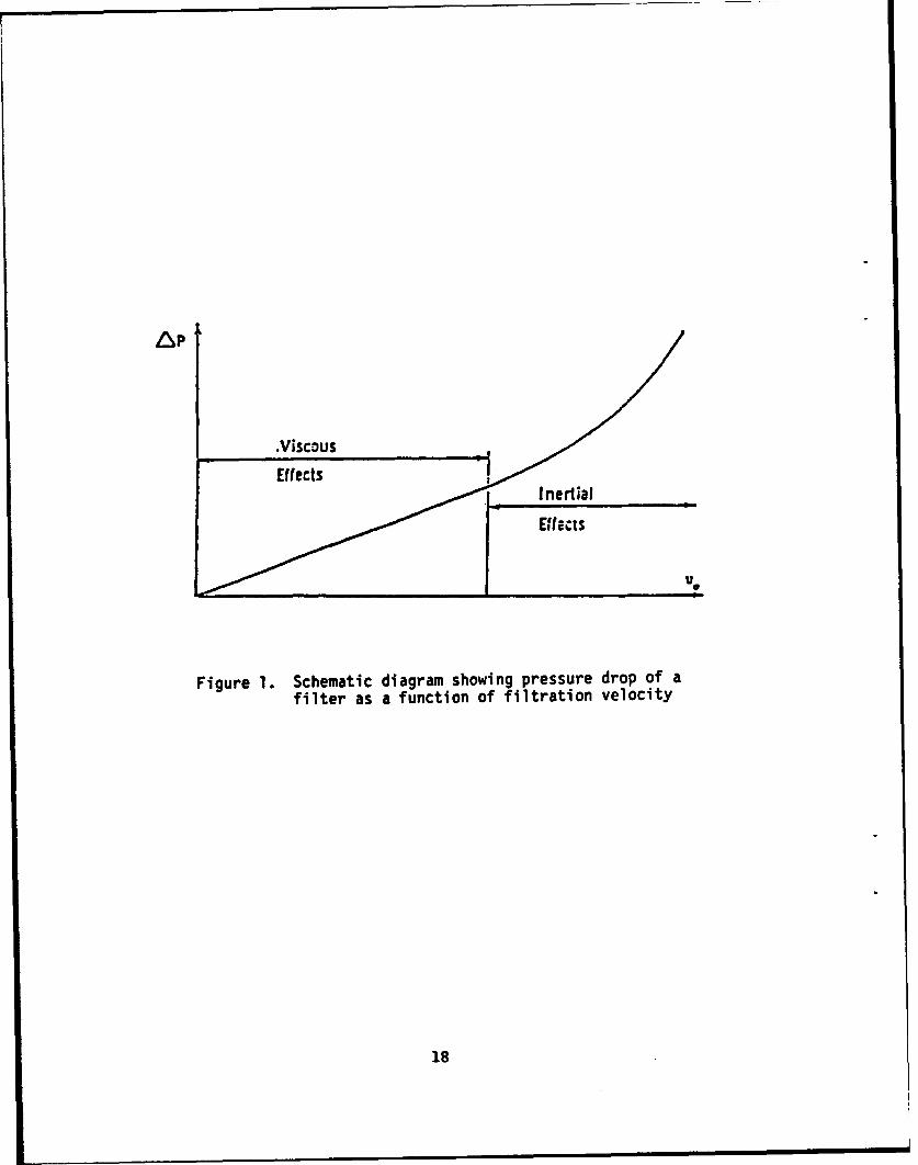
The pressure drop of a filter is usually proportional to the surperficialface velocity of the fluid passing through the filter. At high filtrationvelocities, the pressure drop may increase more rapidly with increasing flowrate due to fluid inertial and turbulent effects. This is illustrated in Figure 1.However, most filters do operate in the linear pressure drop regime, whichis also referred to as the Darcy law regime.
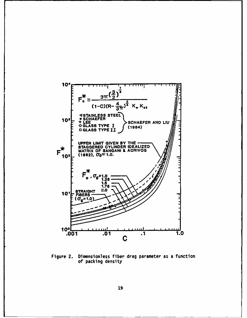
Theory of pressure drop for fibrous filters usually begins byconsidering the drag force exerted by the flowing fluid on the individualfibers in the fiter. The specific fiber drag, Fd. i.e. the drag force per unitfiber length, can then be related to the total pressure drop of the fluidthrough the filter,
AP = IfFd (1)
where If is the total length of fibers in a unit ifiter area. In the Darcy law
regime, AP is proportional to the fluid velocity, u, and viscosity. m.Consequently, Fd is also proportional to these quantities,
Fd = F* t u (2)
12

where F* is a dimensionless constant of proportionality known as thedimensionless fiber drag parameter.
The mathematical theory of fibrous filtration shows that thedimensionless fiber drag parameter, F*, is a function of the packing density,a, of the fibers in the filter. The widely used Kuwabara theory of filterpressure drop predicts the following functional dependence of F* on a,
4nF* =-r- (3)
where K is the hydrodynamic factor
K=llna +a a2 4 (4)
The actual pressure drop through a filter is usually smaller than thatpredicted by theory due to the fact that some part of the fiber in a filter islocated in the wake region of another fiber and these fibers do notexperience the full hydrodynamic drag. The ratio of the theoretical to actualfilter pressure drop is usually in the vicinity of 1.6 according to themeasurement of Yeh and iu I1 and Lee and Liu [2,3] among others. Acomprehensive measurement of the relationship between F* and a has beenmade by Shaefer and Liu [41 and by Monson [5 over a wide range of values ofa . The results are shown in Figure 2.
Filter Efficiency
For air or gas filtration, the efficiency of the filter for particle captureis due to the mechanisms of diffusion, interception and inertial impaction.Diffusion refers to the random Brownian motion of the particles resultingfrom molecular impact by the surrounding gas molecules. Interceptionrefers to the capture of a particle as a result of the finite size of the particlewhen it is brought to the vicinity of the fiber by the flowing gas stream.Capture by inertial impaction is a consequence of the finite mass andmomentum of the particle causing the particle to deviate from the
eamline and impact on the collecting fiber. These mechanisms areillustrated in Figure 3. For high efficiency filters, diffusion is usuallydominant for small particles below 0.1 gm and interception, for particleslarger than 1 gm. In the size range between 0. 1 and 1.0 gm, both diffusionand interception are important and must be considered. Inertial impactionmay become important for large particles or when the filtration velocity ishigh.
13
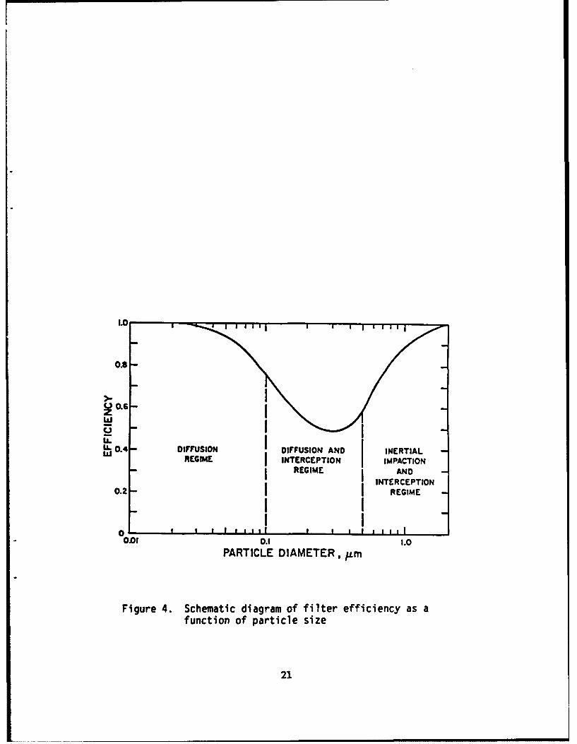
The operation of the diffusion, interception and inertial mechanismsof filtration generally leads to a filter efficiency characteristics as shown inFigure 4. In the small particle size range where diffusion dominants, thefilter efficiency would decrease with increasing particle size, because theparticle diffusion coefficient generally decreases with increasing particlesize. On the other hand, in the large particle size range where interceptionand inertial impaction dominate, increasing particle size generally leads toan increase in filter efficiency. The combination of these mechanisms wouldlead to the existence of a minimum in the filter efficiency in someintermediate particle size range as shown in Figure 4. The existence of aminimum in the filter efficiency versus particle size curve in air and gasfiltration is well documented both theoretically and experimentally.
In contrast to gas filtration, liquid filtration by fibrous or membranemedia generally does not involve capture by diffusion or inertial impaction asthese effects are usually negligible in liquids. Consequently, filtration ofparticles by liquids often involves pure interception only, and particlecapture is reduced to a screening effect. Particles smaller than the poreopenings in the filter usually will pass through the filter while those largerthan the pore opening will be retained.
The mathematical theory of gas filtration by fibrous filters usuallybegins by defining a single fiber efficiency. I., the fraction of particlescollected by a fiber from a volume of air geometrically swept out by the fiber.The single fiber efficiency is related to the overall efficiency of the filter, 11,by the simple exponential relationship.
ii= 1- e - TlslfDf (5)
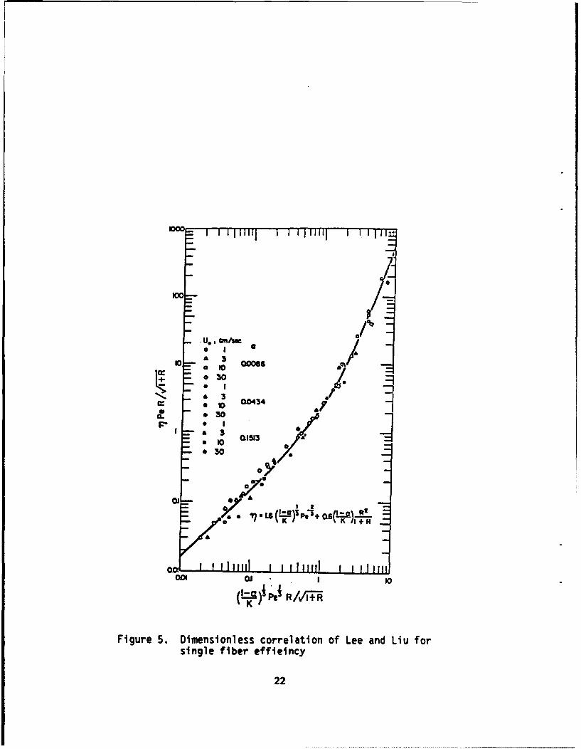
An extensive series of measurements on single fiber efficiencies hasbeen reported by Lee and Liu [2,31 who varied the filter packing density,filtration velocity and particle size over a wide range of values. Their resultscan be correlated by a dimensionless plot involving the Peclet number,
U DfPe -(6)
and the interception parameter
14

DR 13(7)
Df
where D is the particle diffusion coefficient and D and Df are respectivelythe particle and fiber diameters. Their results are stown in Figure 5.
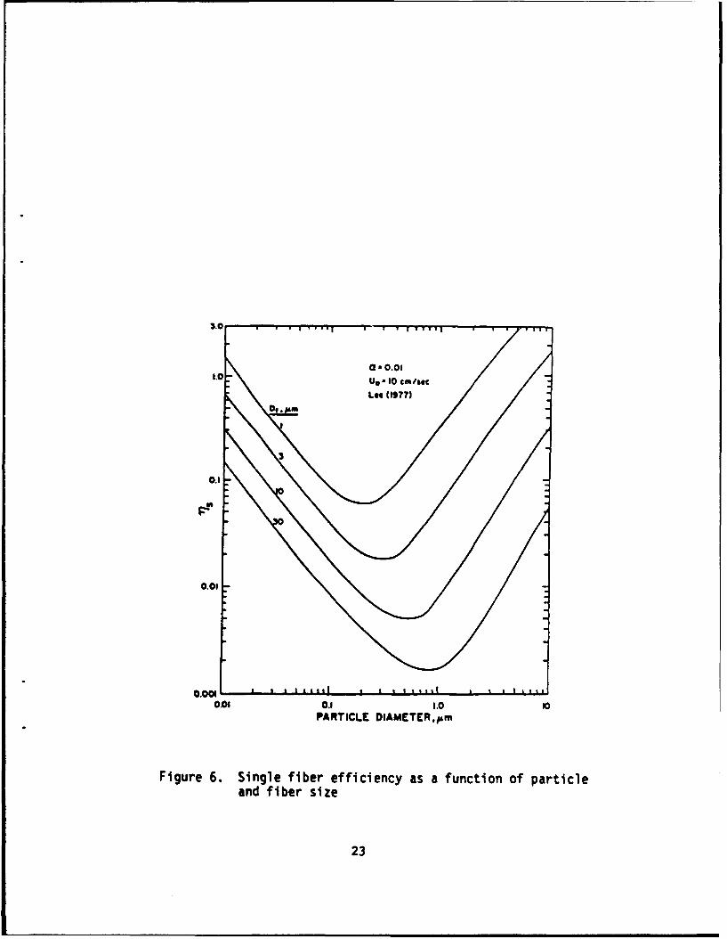
The theoretical dependence of the single fiber efficiency on fiber andparticle size is shown in Figure 6. It is interesting to note the existence ofthe minimum in filter efficiency and that the single fiber efficiency generallyincreases with decreasing fiber size. This underscores the advantage ofusing small fibers in making filters.
Performance of Filters and Filter Testine
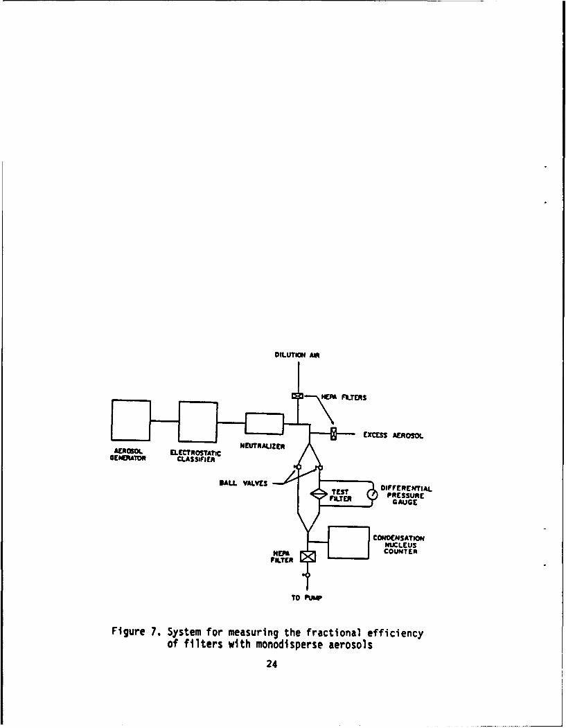
The performance of an actual filter usually must be determined bytesting. To measure the efficiency of a filter as a function of particle size, itis usually necessary to generate a monodisperse test aerosol and measuringthe concentration of the aerosol upstream and downstream of the filter todetermine the aerosol penetration, P. through the filter. The collectionefficiency is then equal to 1 - P.
Figure 7 shows a system developed at the University of Minnesota formeasuring filter efficiency by means of monodisperse test aerosols. Theaerosol is usually generated by an electrostatic classification method and theparticle size can be varied systematically over a range of particle sizes,usually between 0.03 and 1.3 pm. The concentration of the aerosol upstreamand downstream of the filter is usually measured with a condensationnucleus counter.
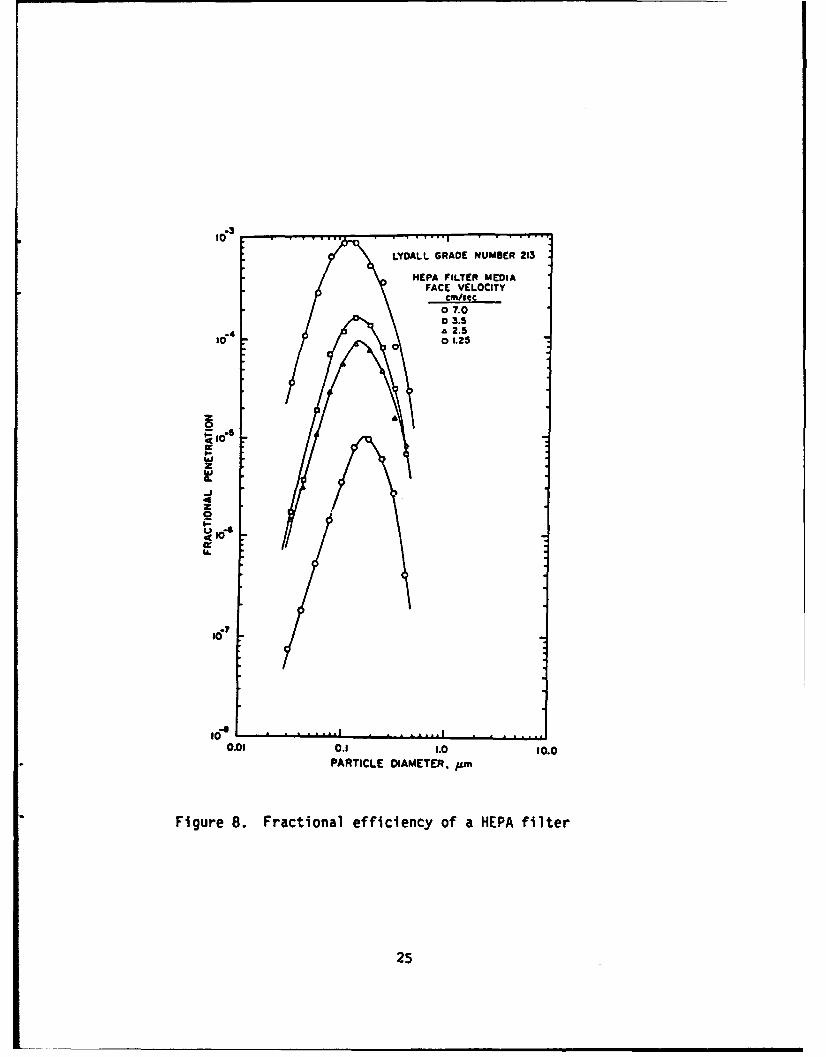
Figure 8 shows the measured penetration through a commerciallyavailable high-efficiency particulate air (HEPA) filter. It is interesting to notethat the filter penetration first increases with increasing particle size,reaching a peak at a particle size of approximately 0.1 to 0.2 Im, after whichthe penetration decreases with further increase in particle size. This iscompletely in accord with the theoretical predictions as discussed above.
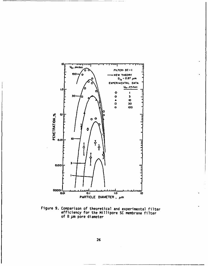
Measurement of the efficiency of membrane filters shows that theperformance of the membrane fiter is quite analogous to that of fibrousfilters. Indeed the study of membrane fiter by Rubow [61 shows that theperformance of the membrane fiter can best be correlated with the fibrousfiltration theory and that the equivalent fiber size for a membrane fiter isquite close to the size of the structural elements in the membrane media.Figure 9 shows a comparison of the theoretically calculated filterpenetration with the measured value for a Millipore SC membrane filter witha nominal pore size of 8.0 gim. The equivalent "fiber size" used in the
15
calculation is 0.87 gm which is close to the size of the structural element inthis particular membrane.
For the filtration of high purity gases used in semiconductormanufacturing, it is necessary to provide a high degree of filtration and tomake use of a filter media that is non-shedding. For this purpose membranefiters are commonly used. One widely used fiter is the Millipore 0.2 gmPVDF Durapore filter. Testing of this filter by Rubow and Liu (7] andAccomazzo et al [81 show a fiter penetration of less than 1 x 10⁻⁹ , which islimited by the sensitivity of the test method used.
Summar
This paper has provided a summary of the mechanisms and theory offiltration as they relate to high purity air or gas filtration. The major capturemechanisms for particles in a filter are diffusion, interception and inertialimpaction. These mechanisms have led to the existence of a mostpenetrating particle size for fiters, which for fibrous media is usually in thevicinity of 0.1 to 0.2 gm. The use of monodisperse aerosols for filter testingis then discussed and the performance characteristics of some commerciallyavailable filter is then described.
References
1. Yeh, H. C. and Liu. B. Y. H., "Aerosol Filtration by Fibrous Filters--PartII. Experimental," J. Aerosol Sci.5:205-217, 1973.
2. Lee, K.W. and Liu, B. Y. H.. "Experimental Study of Aerosol Filtration byFibrous Filters," Aerosol Sci. Technol. 1:35-46, 1982.
3. Lee, K W. and Liu, B. Y. H., 'Theoretical Study of Aerosol Filtration byFibrous Filters," Aerosol Sci. Technol. 1:147-162, 1982.
4. Schaefer, J. W. and iUu, B. Y. H. , "An Investigation of Pressure LossAcross Fibrous Filter Media," Aerosols: Science. Technology andIndustrial Aplications (B. Y. H. Liu, D. Y. H. Pui and H. Fissan, Editors),pp. 555-558, Elsevior Science Publishing Co., New York, 1984.
5. Monson, D. R., "A Filter Pressure Loss Model for Uniform Fibers,"Aerosols: Science. Technology and Industrial Applications (B. Y. H. iu.D. Y. H. Pui and H. Fissan, Editors), pp. 551-554, Elsevior SciencePublishing Co., New York, 1984.
6. Rubow, K. L., "Submicron Aerosol Filtration Characteristics ofMembrane Filters," Ph.D. Thesis, Mechanical EngineeringDepartment, University of Minnesota, Minneapolis. Minnesota, 1981.
16

7. Rubow, K. L. and Liu, B. Y. H., "Evaluation of Ultra-high EfficiencyMembrane Filters," Proceedings of the 30th Annual Technical Meetingof the Institute of Environmental Sciences, pp. 64-68, 1984.
8. Accomazzo. M. A., Rubow, K. L. and Liu, B. Y. H., "Ultrahigh EfficiencyMembrane Filters for Semiconductor Process Gases," Solid StateTehnohgL pp. 141-146, March, 1984.
17
/Sp
.Viscous
Ef fects
Figure 1. Schematic diagram showing pressure drop of afilter as a function of filtration velocity
18
104
4 STAINLESS STEEL103 * SCHAEFER
LEE SCHAEFER AND LIUO GLASS TYPE Il
UPPER LIMIT GIVEN BY THE* STAGGERED CYLINDER IDEALIZED
F102 MATRIX OF SANGANI & ACRIVOSi2 (1982). rg=1.O.
11.0
1gur 2.TDReIones fibe drgprmtr safntoFpakigEenit
ag= i9

Patcle Trajectory
Ilk , IFlow stroamlirao
(a) Drownian Diffuzion,
r 1awi Streamline
(b) Direct Inte.rception
Fl~ow Strcoaiiine
(c) Inertial Impaction
Figure 3. Schematic diagram of filtration mechanisms
20
0.8-
0.6- IILIL_,1. I I
L0.4 DIFFUSION 'DIFFUSION AND INERTIALREGIME INTERCEPTION IMPACTION
INTERCEPTION0.2 I I REGIME
I I-0.01 0.1 0I
PARTICLE DIAMETER, im
Figure 4. Schematic diagram of filter efficiency as a
function of particle size
21
c
II
0 100 3
-- •U . * m //e Q
• I I
- £ I0 00434
a. - •30
-. e ., -S- *310 1513
#30
Of O'-A
001 OW I 30
Figure 5. Dimenslonless correlation of Lee and Liu for
single fiber effleincy
22
1.0 UO - 10 cm /ac
0..
0.1
0.001 gD.1 0.1 1.0 0
PARTICLE DIAMETER~pm
Figure 6. Single fiber efficiency as a function of particle
and fiber size
23
DILUTION AIR
GENOTOR CLASSIFIER
SALL VLVESOIFFERENETIALTEST PRESSUREFILTERGAUGE
CONDENESATIONENUC LEUS
HEMA COUNTERFILTER
TO PUWP
Figure 7. System for measuring the fractional efficiencyof filters with monodisperse aerosols
24
.,3
LYDALL GRADE NUMBER 213
NEPA FILTER MEDIAFACE VELOCITY
cm/seco07.0o 3.5
.4 &£2.5
tO a 01.25
0
I-4
22
U0. @'n/uec0 FILTER, SC -I
too 0 -NEW THEORY0 Oft , 0.87 pm
O EXPERIMENTAL DATA
1.0[ 00 U. Cf'ec0 1
30 0 0 3A 10O 300 100
2 0
I.-
1.- 0
.01-o 10
0.001: 3
0.01 0.1 1.0 10
PARTICLE DIAMETER .
Figure 9. Comparison of theoretical and experimental filterefficiency for the Millipore SC membrane filterof 8 pm pore diameter
26

SECTION II: PARTICLE PRODUCTION AND DISSMINATION
27

Blank
28
Particle Generation in Aerosol Reactors
Dr. David T. Shaw,State Uniuerity of New York, Buffalo
Abstract by Erica R. Riley, CRDEC
The decomposition of metal carbonyls is a convenient system to study in addressing the prob-lem of chain aggregate formation in aerosol reators. Carbonyls are readily dissociated by irradiationas well as by direct thermal application. Dissociation products combine with available species toform metal or metal oxide particles that subsequently aggregate into chain-like morphologies. Pro.duct morphology can be controlled by using alternate methods of decomposition and by adjustingoperating parameters of the various reactors.
The system used in these studies was the decomposition of iron pentacarbonyl in the presence
of an oxygen source to form chains of iron oxides:
PC (CO0)s light or heat, 02 > Fe203
In this type of formation, the initial step is decomposition of the carbonyl to provide atomic iron andmolecular carbon monoxide. This step is followed by nucleation of iron oxide particles and growthof these nuclei by surface condensation. These spherical particles generally reach sizes on the orderof 200 angstroms before they aggregate into chain structures. The chains can then coagulate andgrow further by additional condensation. Phenomena associated with each of these steps can affectproduct morphology.
There are four well-known methods for dissociating the carbonyl in this type of system andeach method provides slightly different products. The most popular of this is simple thermal decom-position. In this method carbonyl vapor is carried in a hot gas stream to a heat zone (T > 160C)where the reactions occur. Generally this produces spherical particles with diameters on the order ofthe magnetic domain size, Le. d > 200 angstroms. The formation of chain aggregates of magneticmaterials by this method can be further controlled by the application of magnetic fields. Directthermal dissociation can also be achieved in a flame generator. In this type of process the charac-teristics of the flame itself become important factors. As the particles enter the atmosphere theypass through the high temperature part of the flame and experience rapid cooling effects, droppingin temperature at a rate of 10' degrees per second. The spherical particles associated with this typeof process are generally less than 200 angstroms in diameter.
The other two methods are associated with laser irradiation. Using a C0 2 laser operating at10.6 microns, a 0.7 volt 50 nanosecond pulse causes 'instant' vaporization of carbonyl droplets. Theproduct of this system is yFe2 O5 . Departing from the traditional thermal decomposition process,these reactions can be initiated by photodissociation of the carbonyl. This has been done using anaxcimer laser operating at 193 nanometers. The ultraviolet radiation dissociates the moleculeswithout heating. Several purposes are served by this approach. The nuclei are cold and inhibitcoagulation and aggregation. The product of this process is ultrafine (" 200 angstrom) particles ofaFe20 . This material is of interest to the semiconductor and microcircuit community, where thereis great need of smooth nonmagnetic materials.
In all of these processes the product parameters such as diameter, crystal structure, aggregatelength and diameter, and degree of coagulation, can be adjusted through process parameters. Theseparameters include but are not limited to application of magnetic fields, adjustments in heating andcooling rates, changes in gas flow rates, temperature ranges and time in generator, and the use ofvarious atmospheric environments.
29

Blank
30
MATERIAL SYNTHESIS BY AEROSOL PROCESSES
Sotiris E. PratsinisDepartment of Chemical and Nuclear Engineering
Center for Aerosol ProcessesUniversity of CincinnatiCincinnati, OH 45221-0171
Aerosol process is any operation or series of operations
that causes a physical or chemical change to a gaseous
suspension of solid or liquid particulates. Individual
particulate sizes may range from molecular clusters (<1OA) up to
10um particles (Friedlander, 1982).
Traditionally aerosol science has been devoted to the
prevention of the deleterious effects of aerosols on human
health and environment. Aerosol engineering is a new discipline
aiming in developing industrial aerosol processes for
manufacture of high technology materials (optical waveguides and
advanced ceramics) and particulate commodities (carbon blacks
and titania pigments).
Aerosol processes are advantageous for manufacture of
particulates since they do not require the several tedious
operations and high liquid volumes of wet chemistry. Thus, the
'chloride' process has gradually substituted the 'sulfate'
process in industrial scale manufacture of titania pigments
(Solomon and Hawthorne, 1983). Aerosol processes can be used
for production of highly pure materials. Hence, in lightguide
fabrication technology aerosol ('vapor' deposition) processes
phased out the double crucible process for manufacture of low
31

loss fibers for telecommunications (Nagel et al., 1982; Kim and
Pratsinis, 1988). Reactant mixing is achieved in much shorter
time scales in aerosol than in wet chemistry processes. These
processes are also energy efficient operations for manufacture
of particulates. A typical example is the production of silicon
for photovoltaic applications. There, the power consumption per
unit silicon mass can be an order of magnitude lower in an
aerosol reactor than in the classic Siemens process (Alam and
Flagan, 1986).
Despite the widespread industrial applications of aerosol
processes their design and operation relies heavily on
experience and empiricism. As a result, it is not surprising
that the particulate industry in United States has not made
virtually any progress in the last 20 years (Merrow, 1985). In
flame aerosol reactor technology, ror example, though several
patents on reactor design, feed additives and reactant mixing
have been filed, the fundamentals of these systems yet have not
been understood (Bowen, 1980).
On the other hand, most basic studies of aerosol processes
have been focused on the investigation of a specific
physicochemical system. Thus, relationships between process
variables and product characteristics have not been developed in
the convenient chemical engineering format: dimensionless
numbers and monographs. Notable exceptions are a Levenspiellian
analysis of standard chemical reactors with respect to product
particle ccncentration, size, polydispersity, surface area and
32

yield (Pratsinis et al., 1986a); the analysis of the effect of
reactant gas mixing on product particle characteristics (Kodas
et al., 1987a); the analysis of particle production by
condensation (Pesthy et al., 1983; Pratsinis et al., 1988); and
the analysis of stirred tank aerosol reactors (Crump and
Seinfeld, 1980; Pratsinis et al., 1986b). Although these
studies were developed for rather idealistic laboratory scale
systems, they provide valuable directions for the design of
industrial aerosol processes (Kodas et al., 1987b).
Development of efficient and simple aerosol processes for
manufacture of advanced materials and particulate commodities is
a major research goal for several domestic and foreign
industries. Design, scale up and control of these processes
motivate the research for construction of comprehensive but
compact models describing the behavior of industrial aerosol
reactors. Invention and development of real time instruments
weasuring production rate, average size and polydispersity of
highly concentrated aerosols is a pressing need of the
particulate industry.
Alam, M.K., Flagan, R.C. Aerosol Sci. Technol. 5, 237 (1986).Bowen, H.K. Mater. Sci. Eng. 44, 1 (1980).Crump J.C., Seinfeld, J.H. AIChE J. 26, 610 (1980).Friedlander, S.K. Aerosol Sci. Technol. 1, 3 (1982).Kim, K.S., Pratsinis, S.E. AIChE J. 34, June (1988).Kodas, T.T., Friedlander, S.K., Pratsinis, S.E. Ind. Eng.
Chem. Res. 26, 1999 (1987a).Kodas, T.T., Sood, A., Pratsinis, S.E. Powder Technol. 50, 47
(1987b).
33
Merrow, E.W. Chem. Eng. Prog. 80(5), 15 (1985).Nagel, S.R., MacChesney, J.B., Walker, K.L. IEEE J. Quant. Elec.-
QE-lB. 459 (1982).Pratsinis, S.E., Kodas, T.T., Sood, A. Ind. Eng. Chem. Res. 27,
105 (1988).Pratsinis, S.E., Kodas, T.T., Dudukovic, M.P., Friedlander, S.K.
Ind. Eng. Chem. Proc. Des. Dev. 25, 634 (1986a).Pratsinis, S.E., Friedlander, S.K., Pearistein, A. AIChE J. 32,
177 (1986b).Solomon, D.H., Hawthorne, D.G. Chemistry of Pigments, Wiley, 1983.
This work was supported in part by NSF grant CBT-8707144.
pp/sp3
34
AN OVERVIEW OF PARTICLE GENERATION FOR OBSCURATION
E.R.Riley
Chemical Research, Development and Engineering CenterAberdeen Proving Ground, MD. 21010-5423
1. INTRODUCTION
Theoretical studies of the interactions of electromagneticradiation with particulate clouds have provided information aboutthe particle parameters required to maximize extinction. Theseparameters are generally related to the size, composition, shape,aspect ratio, conductivity, and optical constants associated withthe individual particles. Designing and generating particles toproduce any specified result in EM interactions involves properchoice of the material and its generation technique. Every methodavailable for particle generation is limited in the types ofmaterials that can be addressed by the technique. The ability totailor a particle to specific meeds depends on full control of awide variety of processes. A number of techniques will bediscussed here, including chill block melt spinning, thermaldecomposition of organometallics, spray drying, vapor depositions,plasma and flame spray techniques and combustion synthesis. Eachhas unique abilities to provide particles with specific properties.
2. TECHNIQUES
2.1. Chill Block Melt Spinning
The concept of chill block melt spinning has been used for mayyears to produce glassy metals and alloys. A stream of molten metalis impinged on a rapidly spinning wheel, cup or disk that is cooledto room temperature or below. The rapid transfer of thermal energyfrom the melt to the wheel results in solidification at rates thatpreclude classical crystallization. This allows formation of solidmetal phases, stable at room temperature, that would otherwise notform. Historically researchers have concerned themselves with theproblem of forming large sheets of glassy metals; however takingthe opposite approach provides a convenient method of rapidlyproducing fine particles. Particle size can be controlled via suchparameters as the speed of the spinning block, feed rate of themelt to the block(s), orifice diameter, melt viscosity, meltvelocity, and cooling rate. Particle shape can be controlled bythe geometry of the melt spinner, e.g. the shape of the block orcombination of blocks, distances between blocks and thermalvariations throughout the system. One example of a versatile melt
35

spinner is a spinning cup surrounded by rotating cylinders. Thecup alone produces needles, cylinders alone produce ribbons orsheets, and both in tandem produce flakes.
2.2 Thermal Decomposition
Thermal decomposition of organometallic vapors can be used fora variety of applications. The material to be decomposed, thethermodynamically stable products, and the temperature, atmosphereand pressure used in the process all control the productcharacteristics. Many of these processes result in ultrafineirregular particles formed by the laws of nucleation andcondensation. However, depending on the identity of the materialsinvolved, additional controlling parameters can be used to alterthe morphological characteristics of the product. One of the mostuseful of these parameters is the addition of a variable magneticfield. Proper use of this in the formation of ferromagneticparticles can result in fibers or whiskers of controllable diameterand length. This control is valuable in light of the theoreticalsignificance of aspect ratio in attenuation mechanisms.
2.3 Spray Drying
Spray drying is extremely valuable in cases where the goal isfine crystals of soluble material. The size and crystallinity ofthe particles produced depends on the temperature profile of thesystem used, the solubility and concentration of the material inthe solvent, and the droplet size, speed, and number concentrationin the drying zone. The effect of varying these parameters isgenerally to control the rate of solvent evaporation and to controlthe population in the drying zone, thus controlling the kinetics ofthe nucleation and condensation processes. The actual effects ofparameter controls on the spray drying process have been thoroughlystudied for numerous solute/solvent systems. The experimentalobservations in these studies are effectively correlated withtheoretical models.
2.4 Vapor Deposition
Deposition processes are generally recognized for their valuein formation of thin films and coatings. There are a number ofdifferent deposition technologies ranging from purely physicalvapor depositions to depositions involving chemical and electricalprocesses. All involve heating of a material, usually in vacuum,to generate a vapor phase. The vapors travel to a substratesurface and condense. Factors controlling the product includepressure, identity of the material being evaporated and of anygases existing in the zone, identity, texture, and cleanliness ofthe substrate, concentration of vapors, rates of evaporation andcondernsation, and stability of the material being evaporated. Thislast factor is often used to advantage in chemical processes.Coevaporation of two reactive materials, or evaporation of a
36
substance into a reactive gas, can provide deposition of a reactionproduct. This type of process is called chemical vapor depositionand there are numerous variations on the theme. Use of theseprocesses in the generation of particulates is limited to caseswhere the desired size is in the realm approachable by mechanicalmanipulation. Ultrathin flakes may be produced via depositionthrough a screen onto a substrate that is later removed.Mechanical cutting of continuous deposited films can also provideflakes or ribbons. The greatest advantage to these techniques isdirect control over the flake production process. This can providemultilayer flakes or flakes of materials which do not naturallyassume this shape.
2.5 Plasma and Flame Spraying
Plasma and flame spray techniques are also traditionally usedin coatings applications. A plasma or flame torch is used tovaporize a material and accelrate the vapor towards a substrate.Controlling parameters include plasma energy, thermophysicalproperties of the material being sprayed, distance between sourceand substrate, cleanliness of substrate, atmosphere, andtemperature profiles. Several methods can be used to adapt thesetechniques to particle production. If no substrate is present thevapors will nucleate and condense in flight as particles such asthe case for carbides and nitrides of silicon forming chainaggregates. Control of the nucleation and condensation rates bycontrol of temperatures and concentrations throughout the zone canprovide variation in particle morphology. Again, size and shapecontrol can be achieved through geometric considerations andrefined morphology can be achieved using electromagnetic fieldsstrategically applied. The advantage of this technique is itsapplicability to high refractory materials.
2.6 Combustion Synthesic
Combustion synthesis of ceramics is one of the fastest andmost cost effective methods of producing high density ceramicparticulates. The technology takes advantage of the thermodynamicstability of the product relative to the reactants and uses thereaction exotherm to feed the reaction and to purge the products ofimpurities. The starting materials are generally powders inelemental form. These are intimately mixed and the reaction isinitiated by an electrical discharge or sudden local thermal flux.A typical example is the reaction of titanium and carbon to formtitanium carbide, or titanium and boron to give the boride. Inthese methods, the manner of particle size and shape controldepends on the alloy system in use. In some cases the productstrictly mimics the morphology of the precursors.
37

Blank
38
CHEMICAL REACTIONS IN AEROSOLS -A NEW TECHNIQUE FOR PREPARATION OFCOLLOIDS OF NARROW-SIZE DISTRIBUTION
Richard E. PartchDepartment of Chemistry and
Center for Advanced Materials ProcessingClarkson UniversityPotsdam, NY 13676
A novel technique has been developed for the preparation ofspherical colloidal organic or inorganic particles which can be ofsimple or mixed composition, or coated. The procedure consists incontacting liquid aerosol droplets of one reactant with a co-reactant in the vapor phase. There are several distinct featuresof this technique which offer certain advantages over thecommonly employed processes for the generation of fine powders.The so produced particles are always spherical and their diametercan be predetermined by the size of the initial aerosol droplets.The materials are of high purity because, in most cases, noextraneous ions, surfactants, or any other additives are involvedin the process. Solids of defined mixed composition can beobtained from droplets of known contents in components. Finally,some extremely rapid reactions may be used in the aerosolprocessing, that are difficult to control by other procedures.
The described technique was employed in the preparation ofspherical particles of narrow size distribution of titania (1),alumina (2), or mixed titania/alumina (3,4). In these cases,droplets of corresponding alkoxides (or mixtures thereof) werereacted with water vapor. Similarly, silica particles wereprepared by exposing SiCl4 aerosols to water vapor and mixedtitania/silica and alumina/silica colloids were produced from thecorresponding metal alkoxide and SiCl 4 (5).
Polymer colloids of styrene (6) or ethylvinyl/divinylbenzene(7) were generated from droplets of monomers in the presence of aninitiator (tritluoromethanesulfonic acid) in the vapor phase. Bythis procedure, it was possible to obtain rather large particles(up to 30 um) which cannot be prepared by conventional techniques,such as emulsion polymerization.
Uniform spherical particles of polyurea were generated usingdroplets of diisocyanate -ivatives and ethylenediamine vapor.Sequential use of metallorc,.nics and organic monomers as startingmaterials yielded mixed particles such as polyurea/TiO2 orpolyurea/A1203 (8).
It is possible to coat inorganic cores with organic coatingsby the aerosol technique. Titania produced as described above waswetted with diisocyanate derivatives in the aerosol phase and thenmixed with the vapor of ethylenediamine. This sequence ofreactions produced a polymeric coating on the titania cores. The
39
thickness of the coatings could be altered by varying experimentalconditions (9).
Aerosol droplets can be obtained either by evaporation/condensation or nebulization. In the former case, the dropletsize and uniformity can be altered by the flow rate of the carriergas and temperature of the apparatus. Nebulization results indroplets, and subsequently particles having wider sizedistribution but allows incorporation of nonvolatile components.Furthermore, microcapsules can be formed around nonreactivematerials (10).
The so obtained colloidal powders find many applications,such as in medical diagnostics, as drug carriers, fillers,coatings, catalysts, or for various special uses n high-techceramics.
ACKNOWLEDGEMENT
This program is conducted in collaboration with ProfessorEgon Matijevic', Clarkson University.
REFERENCES
1. M. Visca and E. Matijevic', J. Colloid Interface Sci., 68,308-319 (1979).
2. B.J. Ingebrethsen and E. Matijevic', J. Aerosol Sci., 11,271-280 (1980).
3. B.J. Ingebrethsen, E. Matijevic' and R.E. Partch, J. ColloidInterface Sci., 95, 228-239 (1983).
4. B.J. Ingebrethsen and E. Matijevic', J. Colloid InterfaceSci., i00, 1-16 (1984).
5. A. Balboa, R.E. Partch and E. Matijevic', "Preparation ofUniform Colloidal Dispersions by Chemical Reactions inAerosols - IV. Mixed Silica/Titania Particles," ColloidsSurf., 27, 123 (1987).
6. R.E. Partch, E. Matijevic', A.W. Hodgson and B.E. Aiken, J.Polymer Sci., Polym. Chem. Ed., 21, 961-967 (1983).
7. K. Nakamura, R.E. Partch and E. Matijevic', J. ColloidInterface Sci., 29, 118-127 (1984).
8. R.E. Partch, K. Nakamura, K.J. Wolfe and E. Matijevic', J.Colloid Interface Sci., 105, 560-569 (1985).
9. F.C. Mayville, R.E. Partch and E. Matijevic', 'Preparation ofUniform Spherical Titania Particles Coated With Polyurea by
40

the Aerosol Technique,"f J. Colloid Interface Sci., 120Q, 123(1987).
10. L. Durand-Keklikian and R.E. Partch, "Microencapsulatioi ofOil Droplets by Aerosol Techniques - I. Metal OxideCoatings," J. Aerosol Sgi., In Press.
41

Blank
42
COLLOIDAL PROCESSES FOR PARTICLE PRODUCTION
V.B. Menon, M.E. MullinsI and M.B. Ranade2
Research Triangle InstituteP.O. Box 12194
Research Triangle Park, NC 27709
INTRODUCTION
In recent years. the need for high purity, chemically homogeneous
particles of uniform size and controlled shape has resulted in the development
of a variety of unconventional techniques for ceramic powder production. The
conventional powder preparation processes involving bulk mixing, calcination,
comminution and classification have serious drawbacks when powders of high
chemical purity and submicrometer size are required. The two approaches
suitable for producing ceramic powders suitable for advanced ceramic
applications are (i) vapor-phase synthesis, and (ii) colloidal synthesis.
This paper describes the common colloidal processes for powder production with
special emphasis on some of the more recent advances in the field.
Colloidal processing is the dominant route for the preparation of
multicomponent oxide systems, because of the ease of mixing solutions of salts
to precise ratios, which can then be converted to oxide powders without
disturbing the chemical homogeneity of the solutions (Johnson, 1987). For
nonoxide ceramic powders, vapor-phase processing still appears to be the more
viable route. The various colloidal processes can be divided into two general
categories; evaporation and precipitation. In the following sections each of
these methods is discussed in greater detail.
EVAPORATION
All colloidal processes involve the diisoluticn of salts such as nitrates,
sulfates, acetates, etc., in a solvent. Evaporation involves dhe removal of
the solvent from a solution of the salt by drying. Simple evaporation by
heating gives coarse crystals and is only suitable for single component
solutions. For multicomponent systems this procedure results in a very
inhomogeneous residue because of the different solubilities of the various
components. The more common approaches to evaporation include spray drying or
roasting, fluidized bed drying, freeze drying, and emulsion drying.
Spray Drying: Segregation can be minimized by dispersing the salt solution
into fine droplets and drying the drops rapidly. In a spray dryer, a liquid
1 Current address: Michigan Technological University,
Houghton, MI.
2 Current address: Particle Technology, Inc., College Park, MD.
43

solution is dispersed into a heated reactor chamber in the form of a mist of
fine droplets. Typical droplet sizes vary from 1-30 pm while typical powder
sizes are in the 0.5-20 Jm range. The liquid is rapidly vaporized leaving
residual particles of dry solid. These solids could, if necessary, be reacted
to form products which can then be separated from the gas stream. Spray
drying has been used for the production of ferrites and magnesium aluminates
from sulfates (DeLau, 1970), and complex mixed oxides of metals such as La,
Mg, Cu, Ti, for making elecrical interconnections of simple electrolysis cells
(Roettanbacher and Schmidberger, 1983).
Spray Roasting: In this process spray drying and subsequent calcination to
form metal oxide are combined into one operation. This process has been
extensively used for the synthesis of oxide powders for ferrite production
(Ruthner, 1985). Messing and coworkers (1987) have used a similar process to
prepare powders of MgO and A1203-ZrO2 . This process, termed "evaporative
decomposition of solutions', uses nitrates, acetates, chlorides, or sulfates
as precursors for the oxide powder.
Fluidized Bed Drying: This technique is similiar to spray roasting except that
the solution is trapped in a fluid bed for drying and decomposition. A
pneumatic nozzle injects solution droplets into a heated fluid bed of the
solid product. By varying the temperature, fluidizing gas flowrate and
solution injection rate, the process can be made continuous, with periodic
removal of product. Advantages of this process include: (i) absence of moving
parts, (ii) formation of granulated powders of relatively high bulk density
and large particle size, (iii) large capacity per unit volume of equipment,
and (iv) excellent mixing and heat transfer rates.
Emulsion Drying: Spray and fluid bed drying are processes where drying is
accomplished in the gas phase. In emulsion drying, the aqueous salt solution
is dispersed in a matrix liquid such as kerosene and then dried. This gives a
rather stable suspension of solid salt particles in kerosene. The particles
are deflocculated, precipitated, filtered, washed and decomposed. Reynen et
44
al. (1983) reviewed the sequence of events that are part of a typical emulsion
drying operation. A water-in-oil emulsion is prepared using suitable surface
active agents with the aqueous phase containing the salts. Once the emulsion
is formed, the solvent can be vaporized by evaporation using vacuum, heated
immiscible oils such as petroleum or kerozene, freeze drying, or by combusting
the emulsion.
Freeze Drying: In contrast to the methods described thus far for solvent
volatilization, freeze drying makes use of sublimation rather than evaporation
for solvent removal. The solution is dispersed into small droplets to
minimize segregation and then rapidly refrozen. Solution droplets are sprayed
into a bath of inmmiscible liquid such as hexane chilled by dry ice or acetone.
The frozen droplets are recovered from the refrigerant and placed onto a
cooled tray in a freeze drying chamber for the purpose of subliming the water.
While freeze drying is quite successful in producing fine, homogeneous ceramic
powders, high capital costs and energy requirements have prevented it from
being used for large scale applications.
A variation of conventional freeze drying is emulsion freeze drying where
the salt solution is encapsulated in an emulsion droplet. Figure 1 shows the
difference between emulsion freeze drying and conventional freeze drying. In
the latter case, an aqueous solution is atomized into the freezing solvent,
while in the former case the emulsion is dispersed into the refrigerant. The
advantage of emulsion freeze drying is that demixing, which is especially
prevalent inside large droplets, is minimized.
Supercritical Expansion: Matson et al. (1986) describe a unique process,
based on the rapid expansion of supercritical fluid solutions, for producing
ceramic powders. When a salt solution is expanded through a nozzle from a
high-temperature and -pressure regime to a low-pressure environment, particles
of the solute material are produced by homogeneous nucleation. Particle size,
agglomeration, and other characteristics can be controlled by manipulation of
the solute concentration, temperature of the preexpansion fluid, and other
parameters of the expansion process. Figure 2 depicts a schematic of the
45

c0
C
00
54
.4 44
~ 1-4
-q.
4.
44
".4
'4.
00
14
$4.
00
46".

Bacgluid Optional u~rntca
Expaxpson
Collectioniaati
RES Expy asion Je Expanson
expansion nth oug a apllrynozlc(atontta cal98)
Region

experimental apparatus. The basic components of the system consist of a pump
capable of producing pressure several times the critical pressure of the fluid
of interest, a region in which the fluid is heated above its critical
temperature, and a nozzle through which the solution is expanded to
atmospheric pressure or below.
This technique, which is currently at the laboratory scale, has great
potential for producing nonequilibrium amorphous powders that are not readily
available by other, more conventional powder production methods (Matson et
al., 1987). Materials that have been prepared using this method include Si02 ,
GeO 2 , and ZrO 2.
PRECIPITATION AND FILTRATION
Precipitation followed by removal of solids by filtration is one of the
oldest techniques for preparation of inorganic and organic powders. In recent
years a variety of inorganic colloids have been prepared in the form of well-
defined particles of different shapes, including spheres (Matijevic, 1986,
1987). Precipitation of single cation salts is done on a large scale in the
ceramics industry to prepare high purity oxides and carbonates. The important
variables are (Johnson and Gallagher, 1978):
(1) pH of the aqueous solution: The influence of pH on the precipitationof hydroxides is obvious in that the OH- concentration appears in thesolubility product. e.g. The precipitation of Al(OH)3 is:
A13+ + 30H- - Al(OH)3.
At very low pH there are insufficient OH- ions in solution. At highpH, the soluble complex Al(OH)4 is formed. A pH of 4-9 is necessaryfor Al(OH)3 precipitation.
(2) Order of mixing and addition of precipitating agent: Generally thesolution of cations is added slowly with stirring to a solutioncontaining the precipitating agent. This allows an excess of theprecipitating agent to be added and, the solubility products of allthe cations are likely to be exceeded simultaneously. The oppositesequence of addition will result in cations that are precipitatedwith inhomogeneities.
(3) Rate of mixing: This parameter affects particle size; finely dividedprecipitates are formed by rapidly mixing cold concentrated solut-ions. Also, high mixing rates inhibit the formation of agglomerates.
48

(4) Presence of other ions in solution: The presence of highconcentrations of electrolytes can destroy the electrical doublelayer around a particle and promote coalescence. The electricalcharge distribution around each particle dictates whether particleswill agglomerate or ,ot. The composition and morphology of particlescan also be greatly affected by the presence of c.er ions. Figure3(a) shows ellipsoidal hematite particles precipitated by aging awater/ethylene glycol solution of ferric chloride. The effect of asmall amount of phosphate ion on a similar system is demonstrated in
Figure 3(b) (Matejevic, 1987). The presence of phosphate ions
completely changes the morphology of the particles.
(5) Impurities: These can be incorporated into a precipitate due toadsorption on particles or by occlusion within flocculates. Slowgrowth, large particle sizes, and equilibrium produce the purestprecipitates.
Other factors include temperature, solute concentration and pressure.
Major advantages of precipitation-based methods for powder production
include the ability to form homogeneous particles of mixed metal oxides, and
the capacity to produce equiaxed (regularly shaped) particles. A recent
application of this type of powder preparation technique is the manufacture of
1-2-3 superconductors. Using salts of yttrium, barium, and copper in various
stoichiometric ratios, a homogeneous powder of yttrium-barium-copper oxide can
be precipitated.
Equiaxed, monodisperse particles that have been prepared by precipitation
are SiO2 (Barringer et al., 1984), T1O2 (Barringer and Bowen, 1982), and A1203
(Sacks et al., 1984).
Precipitation by Alkoxide Hydrolysis: Alkoxides and other metallo-organics
can provide a source of high-purity reactants for precipitation. In this
process, a metal alkoxide is hydrolysed with alcohol and water to precipitate
insoluble hydrated oxides. The hydrolysis reaction can be carried out either
in an aerosol reactor or in an aqueous solution. For example, ZnO powder for
high voltage devices has been produced by hydrolysis of ethylzinc-t-butoxide,
dissolved in anhydrous toluene, in deionized water and ethanol. The ethanol
is present to solubilize the organic liquid in the aqueous solution.
Submicrometer size ZnO powder is formed quantitatively and can be removed by
filtration (Heistand et al., 1986).
49

Fig. 3. Scanning 0electron micrograph of hematite particles obtainedby heating at 100 0C (a) for 7 days a 20 vol% ethylene glycol/watersolution 0.05 mol - dm-3 in FeC13, and 0.03 mol - dm-3 in HCL; (b)for 2 days a 20% ethylene glycol/water solution 0.076 mol - dm-3 inFeCl 3, and 3 x 10⁻⁴ Mol - dm-3 in (NH4)H2P04 (Matijevic, 1987).
50
Alkoxides have also been used to dope other preexisting ceramic particles.
Thus, ZrO 2 has been added to a-A1203 particles by hydrolyzing zirconium
alkoxide in a dispersion of alumina (Fegley et al., 1985).
Hydrothermal Precipitation: Often, alkoxide hydrolysis can be followed by
hydrothermal reaction to give complete conversion of the metal precursor to
the oxide. Titanium ethoxide [Ti(OEt) 4 ] hydrolysis results in partial
conversion to Ti02 . The dispersion containing unreacted ethoxide, when heated
in an'autoclave at 200-3000C at 1.5 - 10 MPa pressure for 4-6 hours gives
TiO2 . Figure 4 shows the sequence of steps involved in the hydrothermal
conversion of Ti-ethoxide to Ti02 and the subsequent processing steps to get a
sintered ceramic product (Heistand et al., 1986).
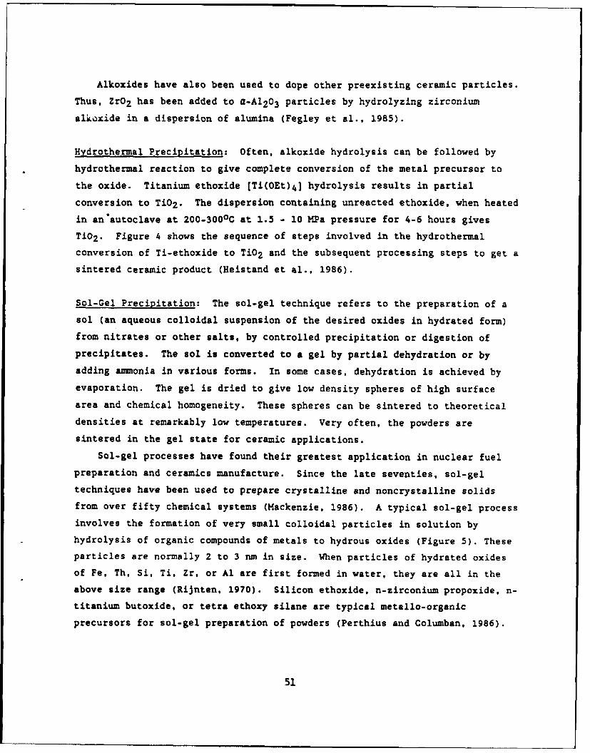
Sol-Gel Precipitation: The sol-gel technique refers to the preparation of a
sol (an aqueous colloidal suspension of the desired oxides in hydrated form)
from nitrates or other salts, by controlled precipitation or digestion of
precipitates. The sol is converted to a gel by partial dehydration or by
adding anmonia in various forms. In some cases, dehydration is achieved by
evaporation. The gel is dried to give low density spheres of high surface
area and chemical homogeneity. These spheres can be sintered to theoretical
densities at remarkably low temperatures. Very often, the powders are
sintered in the gel state for ceramic applications.
Sol-gel processes have found their greatest application in nuclear fuel
preparation and ceramics manufacture. Since the late seventies, sol-gel
techniques have been used to prepare crystalline and noncrystalline solids
from over fifty chemical systems (Mackenzie, 1986). A typical sol-gel process
involves the formation of very small colloidal particles in solution by
hydrolysis of organic compounds of metals to hydrous oxides (Figure 5). These
particles are normally 2 to 3 nm in size. When particles of hydrated oxides
of Fe, Th, Si. Ti, Zr, or Al are first formed in water, they are all in the
above size range (Rijnten, 1970). Silicon ethoxide, n-zirconium propoxide, n-
titanium butoxide, or tetra ethoxy silane are typical metallo-organic
precursors for sol-gel preparation of powders (Perthius and Columban, 1986).
51

RAW MATERIAL {Ti (C2H5Oh4 , CZH 5OH, H2 01
CONTINUOUS REACTION
Ji 2 (Amorphous)
HYDROTHERL REACTION (pH=1O)
Ti-2 (Anatase)
F ILTiRING
Wet ck
DRYING
Green body
SINTERING
Sintered body
Figure 4. Hydrothermal treatment of TiO2 powder(Heistand et al., 1986).
52
Fig. 5. Schematic of a sol-gel process
apparatus (Fleming, 1987).
53
The hydrolysis reaction is achieved by adding a metal hydroxide, chloride, or
nitrate in the aqueous phase. The hydrolysis of metal alkoxides gives a
mixture of the corresponding hydroxide and oxide. Drying leads to the final
powder. Ammonia and aimonium fluoride are catalysts for the gelation process.
Products prepared via the sol-gel route include contact lenses, filters,
catalyst supports, coatings, films, radioactive waste containers, and nuclear
fuel rods.
Emulsion Precipitation: This method is suitable for conducting reactions
between species that are insoluble in each other. For example, yttrium oxide
powders have been made from water-in-oil emulsions containing yttrium ions in
the aqueous phase (Akinc and Celikkaya, 1986). Precipitation of yttrium
hydroxide is accomplished by adding an organic base (triethanolamine) to the
emulsion. Separation of the precursor by dissolution of the emulsion in
alcohol, filtration, and subsequent calcination gives Y203. In this process,
yttrium ions which are oil insoluble are reacted with the triethanolamine base
which is water insoluble, by conducting the reaction at the oil-water
interface.
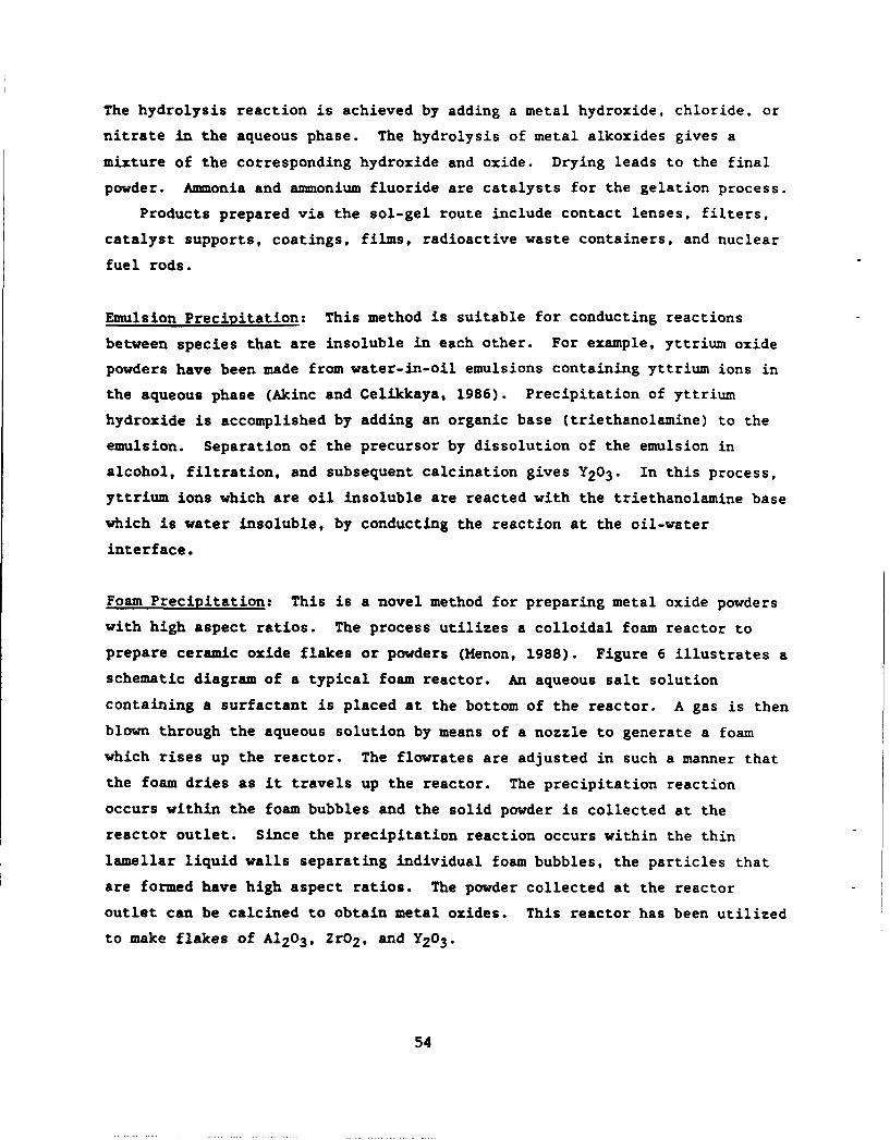
Foam Precipitation: This is a novel method for preparing metal oxide powders
with high aspect ratios. The process utilizes a colloidal foam reactor to
prepare ceramic oxide flakes or powders (Henon, 1988). Figure 6 illustrates a
schematic diagram of a typical foam reactor. An aqueous salt solution
containing a surfactant is placed at the bottom of the reactor. A gas is then
blown through the aqueous solution by means of a nozzle to generate a foam
which rises up the reactor. The flowrates are adjusted in such a manner that
the foam dries as it travels up the reactor. The precipitation reaction
occurs within the foam bubbles and the solid powder is collected at the
reactor outlet. Since the precipitation reaction occurs within the thin
lamellar liquid walls separating individual foam bubbles, the particles that
are formed have high aspect ratios. The powder collected at the reactor
outlet can be calcined to obtain metal oxides. This reactor has been utilized
to make flakes of A1203 , Zr02 , and Y203.
54
Cot ectin U,:~*::~ ~------Soap FoamContainer ~
4T.4
Surfactant Solution
Inlet3Air
Figure 6. Schematic of a foam reactor (Menon, 1988).
55
Molten Salt Precipitation: This form of precipitation eliminates the need for
an aqueous salt solution. The oxide precursors are mixed with a low-melting
salt (such as a eutectic mixture of NaCl and KCI) and heated to temperatures
above the melting point of the salt. The reactant oxides slowly dissolve in
the molten salt and the desired compound precipitates because the product is
only sparingly soluble in the molten salt. The product powder is obtained by
dissolving the cooled salt (Johnson, 1987). This method yields particle sizes
below 0.1 /im, with relatively narrow size distributions. Ferrites and barium
titanates have been prepared by the molten salt method (Hayashi et al., 1985).
SUMMARY
A short review of the various liquid-based powder production techniques is
presented. Advances in ceramics technology require the availability of
submicrometer size particles of narrow size distribution and regular shape.
Currently, these powders can only be prepared by colloidal and vapor phase
methods. However, most colloidal techniques are limited to the production of
metal oxides. Nonoxide ceramics such as carbides, nitrides, and diborides are
becoming increasingly used in electronic and structural applications, and
hence, there is a need for research in the field of nonoxide powder
preparation by colloidal reactions.
56
REFERENCES
Akinc, M.K., and A. Celikkaya. 1986 'Preparation of Yttria Powders by EmulsionPrecipitation," in Advances in Ceramics, Vol. 21 (eds. G.L. Messing, K.S.Mazdiyasni, J.W. McCauley and R.A. Haber), The American Ceramic Society,Columbus, OH., pp. 57-68.
Barringer. E.A., N. Jubb, B. Fegley, R.L. Pober, and H.K. Bowen. 1984'Processing Monosized Powders,' in Ultrastructural Processing for Ceramicsand Glasses (eds. L.L. Hench and D.R. Ulrich), Wiley and Sons, New York,pp. 315-333.
Barringer, E.A., and H.K. Bowen. 1982 'Formation, Packing, and Sintering ofMonodisperse TiO 2 Powders,' J. Am. Ceram. Soc., 65: C-199.
DeLau, J.G.M. 1970 'Preparation of Ceramic Powders from Sulfate Solutions bySpray Drying and Roasting,' Am. Ceram. Soc. Bull. 49:572.
Fegley, B. Jr., P. White, and H.K. Bowen. 1985 'Preparation of Zirconia-Alumina Powders by Zirconium Alkoxide Hydrolysis," J. Am. Ceram. Soc., 68:C-60.
Fleming, J.W. 1987 'Sol-Gel Processing of Glass Powders,' in Advances inCeramics, Vol. 21 (eds. G.L. Messing, K.S. Mazdiyasni, J.W. McCauley andR.A. Haber), The American Ceramic Society, Columbus, OH., pp. 155-162.
Hayashi, Y., T. Kimura, and T. Yamaguchi. 1985 'Preparation of Rod-ShapedBaTiO3 Powder,' Am. Ceram. Soc. Bull., 64: 1249.
Heistand, R.H., Y. Oguri, H. Okamura, W. C. Moffatt, B. Novich, E.A.Barringer. and H.K. Bowen. 1986 'Synthesis and Processing of SubmicrometerCeramic Powders," in Science of Ceramic Chemical Processing (eds., L.L.Hench and D.R. Ulrich), Wiley and Sons, New York.
Johnson, D.W.Jr. 1987 'Innovations in Ceramic Powder Preparation,' in Advancesin Ceramics, Vol. 21 (eds. G.L. Messing, K.S. Mazdiyasni, J.W. McCauleyand R.A. Haber), The American Ceramic Society, Columbus, OH., pp. 3-19.
Johnson, D.W.Jr., and R.K. Gallagher. 1978 'Reactive Powders Solution,' inCeramic Processing Before Firing (eds. G.Y. Onoda, Jr., and L.L. Hench),Wiley Interscience, New York.
Mackenzie, J.D. 1986 'Applications of the Sol-Gel Method: Some Aspects ofIndividual Processing,' in Science of Ceramic Chemical Processing (eds.L.L. Hench and D.R. Ulrich), Wiley Interscience, New York.
Matejevic, E. 1987 'Colloid and Interface Aspects of Ceramic Powders," inAdvances in Ceramics, Vol. 21 (eds. G.L. Messing, K.S. Mazdiyasni, J.W.McCauley and R.A. Haber), The American Ceramic Society, Columbus, OH., pp.423-438.
57

Matejevic, E. 1986 'Colloid Science of Composite Systems," in Science ofCeramic Chemical Processing (eds. L.L. Hench, and D.R. Ulrich), WileyInterscience, New York.
Matson, D.W., R.C., Petersen, and R.D. Smith 19R7 "Production of Fine Powdersby the Rapid Expansion of Supercritical Fluid Solutions," in Advances inCeramics, Vol. 21 (eds. G.L. Messing, K.S. Mazdiyasni, J.W. McCauley andR.A. Haber), The American Ceramic Society, Columbus, OH., pp. 109-121.
Matson, D.W., R.C. Petersen, and R.D. Smith. 1986 "Formation of Silica Powdersfrom the Rapid Expansion of Supercritical Solutions," Adv. Ceram. Mater.1: 242.
Menon, V.B. 1988 "A Novel Process for the Production of Ceramic Flakes," U.S.PatentAppl. Ser. No. 07/195,649.
Perthius, H., and Ph. Columban. 1986 "Sol-Gel Routes Leading to NASICONCeramics," Ceram. Intl., 12: 39.
Reyner, P., H. Bastius, and M. Fiedler. 1983 "The Use of Emulsions in thePreparation of Ceramic Powders," in Ceramic Powders (ed. P. Vincenzeni),Elsevier, Amsterdam, pp. 499-504.
Rijnten, J.J.'1970 in Physical and Chemical Aspects of Sorbents and Catalysts(ed. B.G. Lindsen), Academic Press, London.
Roettenbacher, R., and R. Schmidberger. 1983 "Preparation of Special Ceramicsfor High Temperature Applications," in Ceramic Powders (ed. P.Vincenzini), Elsevier, Amsterdam, pp. 539-546.
Ruthner, M.J. 1985 "Spray-Roasted Iron Oxides: The Nature of MinorImpurities," in Advances in Ceramics, Vol. 15 (ed. F.F.Y. Wang), TheAmerican Ceramic Society, Columbus, OH., pp. 103-107.
Sacks, M.D., T.Y. Tseng, and S.Y. Lee. 1984 "Thermal Decomposition ofSpherical Hydrated Basic Aluminum Sulfate," Am. Ceram. Soc. Bull., 63:301.
Sproson, D.W., and G.L. Messing. 1987 "Ceramic Powder Synthesis by ThermalReaction of Atomized Solutions," in Advances in Ceramics, Vol. 21 (eds.G.L. Messing, K.S. Mazdiyasni, J.W. McCauley and R.A. Haber), The AmericanCeramic Society, Columbus, OH., pp. 99-109.
58
LIPID TUBULE MICROSTRUCTURES:FORMATION, METALLIZATION, AND APPLICATIONS
Dr. Paul SchoenNRL
Washington, DC
ABSTRACT
The polymerizable lipid, DC8 9PC, has been shown to formhollow, cylindrical microstructures called tubules, whose lengthsrange from 10's to 100's of microns and whose diameters are about0.4 microns. We have been investigating their mechanisms offormation, their molecular structure, techniques for controllingtheir growth, and for metallizing and encapsulating them inpolymer matrices.
59

Blank
60
DISPERSION AND DISSEMINATION OF DRY POWDERS
M.B. (Arun) RanadeParticle Technology, Inc.
Building 335College Park, MD 20742
Dispersion of dry powders is often required to produceairborne obscuration smokes. The effectiveness of obscurationsmoke strongly depends on the ability to separate individualprimary particles in the dissemination. High aspect ratioparticles of micrometer or smaller dimensions are very effectivesmokes for a wide wavelength coverage. Spherical submicrometerparticles such as titania are also effective in visible range.These size features also make their dissemination and dispersiondifficult because of high interparticle attraction resulting intheir agglomeration. Dispersion of dry powders is also needed inusing aerosol instruments for size analysis and also for sizeclassification of powders in narrow size fractions.
Dry powders may contain loose agglomerates, hard aggregatesand depending on particle size, shape, and other physicalproperties may be free flowing or cohesive. Successful dispersionof powders in air will depend on these factors as well as theenergy used in tL.3 dispersion process.
Forces between solids are predominantly attractive in natureand cause adhesion of particles to each other and to surfaces.These forces become increasingly significant for fine particlessince the particle mass varies to the third power of the particlesize. The principle forces encountered in most particle adhesionproblems arise out of molecular interactions, electrostaticinteractions, mechanical interlocking, liquid bridges, double-layer repulsion and chemical bonds such as hydrogen and metallicbonds.
The tensile and shear strengths of powders are determined byinterparticle forces and influence the dispersibility of powdersin fluids. Dispersion in air requires separation of adheringparticles from agglomerates and/or external surfaces on which theparticles are collected. Fine powders dispersion in air asindividual micrometer or smaller size particles is especiallydifficult since molecular interactions are stronger in air thanin liquids, and surfactants cannot be used to create repulsion.Environmental parameters such as humidity also make dispersiondifficult. Even non-hygroscopic powders of micrometer and smallerdimensions clump at relative humidities >60%.
For efficient particle dissemination two basic particleattributes must be considered: (1) particle surface compositionand (2) particle size and geometry. Particle surface compositionplays a major role in the adhesion between particles which inturn affects a powders dissemination characteristics. Particlehardness (deformability), chemical composition, and the chemical
61
composition of any liquids used to assist in the fillingtechniques have a profound effect on the van der Waalsinteractions or on any capillary bonding effects that may bepresent.
Ranade and Goyal (1976) studied dispersion of sphericalaluminum powders in vacuum. It was shown that the dispersibilityof the powder correlated well with the powder tensile strength aswell as with the measured force of adhesion between aluminumspheres to plates. Effectiveness of several powder treatmentswere evaluated by measurement of dispersibility and tensilestrengths. Flow agents such as fumed silica improved flow but notthe individual particle separation. A steam treatment whichincreased surface hardness reduced the tensile strength of thepowder and improved dispersibility.
Ranade, et al. (1984), also developed the steam treatment andanother silation treatment which produced a thin layer of silicafor aluminum flakes (0.2 Vm thick, 1-14 pm in diameter). It wasshown that the treatments retained the desired infrared absorptionof the material when only a surface structure modification ratherthan complete conversion to hydroxide using the steam treatment.Dispersibility of the powder was significantly improved.
Dissemination of powders involves two steps: (1) delivery ofthe powder to the dispersion apparatus and (2) dispersion andentrainment in an air stream.
Delivery of powders to the dispersion device suffers from allthe problems associated with powder flow. A metered powder may bedispersed and agglomerates broken up by using the energy of aturbulent air jet, or by impacting the particles on a solidsurface or by collisions between fluidized bed particles. Theresulting aerosol may possess appreciable electrical chargecreated by particle collisions with each other and the hardware.Such charges are strongly dependent on environmental variablessuch as humidity and specific powder and construction materials.Charge neutralizers may be needed to ensure reproducibledispersions.
DISPERSION HARDWARE
Ejectors using compressed air can be used to entrain powderparticles which are subjected to mixing with high speed jets.Successful dispersion results if the energy in the jets isadequate to overcome interparticle forces. Sonic and sub-sonicjets are used. The sub-sonic jets are usually effective for non-cohesive powders and sonic velocities are necessary for cohesivepowders. The powder delivery to the jet is by aspiration from acontainer or a fluid bed. These devices can be used on acontinuous basis with the help of a rotary turntable or a movingrack on which the particles may be packed in grooves and cavities.
62
A typical fluidized bed dispersion device requires higher airflow rates to achieve better dispersion, but an upper limit for theflow rate is set by the onset of air entrainment of the dispersionaids in the effluent stream. Large beads (100-200 micrometers) areoften used to achieve a stable fluidized bed and to break upagglomerates. Mechanical vibrations to a mixer or fluidized bedmay help in improving dispersion. An ultrasonic vibratinggenerator is one such variation. The powder is placed on acylinder which is vibrated in an ultrasonic bath (frequency around50 KHz) filled with water. Compressed air flows through the bed ofparticles which may additionally be mechanically vibrated. Theperformance of a vibrating bed generator is governed by factorssuch as the amplitude and frequency of the mechanical vibrations,particle size, number concentration and shape. Fluidized bedgenerators are subject to very high levels of electrical chargescaused by the multiple collisions and use of charge neutralizers isessential.
The NBS dust generator carries the powder through the spacesbetween the teeth of a metering gear. The powder is sucked up frombetween the teeth by a compressed air ejector which is positioneddiagonally to extract the powder. An impactor plate at the ejectorremoves any large agglomerates. The NBS generator can achieve highoutput concentrations.
Batch dispersion of powders can also be achieved on a smallscale using a shock wave. The shock wave is generated by therupture of a diaphragm separating a high pressure region from a lowpressure region. Since extremely high shock speeds can beachieved, dispersion efficiencies are also higher than most othermethods.
Conditioning of the dispersed dust may be necessary to removelarge agglomerates not broken by the dispersion process. Aninertial separator such as a cyclone or an impactor may be used tocut off the size of the dust at a required upper size. Anaccumulation chamber may be used to remove large particles bygravity settling and to smooth out concentration and pressurefluctuations.
If the dispersion process produces highly charged aerosolsneutralization may be achieved using a bipolar ion generator usingan AC corona or a radioactive source such as Kr-85.
REFERENCES
Ranade, M.B. and A. Goyal, "Research on Coatings or SurfaceTreatment of Metal Powders," Final Technical Report, RADC-TR-76-355, 1976.
63

Blank
64

SECTION III: SAMPLING AND MEASUREMENT OF AIRBORNE PARTICLES
65

Blank
66
AEROSOL SAMPLING AND MASUREMENT
James W. GentryUniversity of Maryland
College Park, MD
Arguably the majority of instruments used to measure theaerosol size distribution are based upon aerodynamicclassification. These instruments incorporate one of threemechanisms -- the persistence of particle inertia relative to thecarrier gas is exploited, the steady-state velocity in anelectrical or gravitational field is utilized, or the averagebehavior of the particles undergoing stochastic fluctuations inposition or velocity is exploited. Each of these mechanisms ischaracterized by a different dimensionless parameter and eachserves as the basis for specific instrumentation. As a firstapproximation they can be assumed to cover different size rangeswith the largest particles classified by inertial mechanisms andthe smallest particles determined from measurements of thediffusion coefficient. There is considerable overlap among themechanisms for the different size ranges.
In selection of the appropriate instrument several criteriamust be considered. These include the methodology for particlemeasurement (is the mass or the particle number measured?; aresingle particles or an averaged variable measured?; is themeasurement on-line or at ambient conditions?), the proceduresused for data analysis, and the morphology of the particles.
By far the most widely used inertial classifier is thesequential-stage cascade impactor. In this instrument theparticle stream passes through a sequence of 6-8 successivestages. In each stage the direction of the flow stream is alteredby 90 degrees due to the presence of a blocking surface.Particles with sufficient inertia are unable to follow the streamimpact on the surface and are collected. The collectionefficiency for these instruments can be characterized by theStokes Number, a dimensionless parameter which is the ratio of thekinetic energy to the work necessary to overcome the dragresistance. Such instruments operate most effectively with largerparticles (Dp > 2 m) and the measurements are based on an integralrather than individual particles. Most often the size isdetermined from gravimetric measurements of the mass collected ona stage. The mass may be determined by weight or less frequentlyby using a radioactively labeled aerosol. Such devices usuallyhave a sharp separation around Stk = 0.25 and are operated as fouror more stages in sequence. In recent years the cut-off size hasbeen extended to smaller sizes by utilizing the increase inmobility which occurs when the mean free path of the carrier gasincreases at low pressures. At these lower pressures there is anincreased complexity in collection mechanisms. A seconddifficulty can arise for solid particles where there is bounce andeventual reentrainment. This is a more serious problem for largerparticles. Generally the behavior of non-spherical particles is
67

not known, as their alignment in the flow field results insubstantially different behavior than for isometric particles.Several different geometries of inertial impactors have beensuggested including those of Casella, Anderson, May, Mercer, andBerner. However the behavior of each of the instruments aresubstantially the same.
Several other instrument designs have been based on theprinciple of the inertial impactor. These include the virtualimpactor where the particles are decelerated by a dead spacerather than a collecting surface and the Prodi inertialspectrometer where the particle stream is introduced parallel tothe collection surface rather than perpendicular as in mostinertial impactors. The latter shows a sharp separation and isespecially suitable for electron microscopy. A second approach isa single particle counter based on the deceleration of a particleas it emits from a jet. Calibration has proved a problem for non-spherical particles and even large spherical particles where thereis some deformation in the flow field. These instruments havebeen designed to overcdme perceived complexities such asreentrainment, averaging over diverse shapes, comparatively broadsize classes per instrument, and working with volatile particles.The key features of such instruments are the sharp separations anda robustness in the instrument so that it can be used in hostileand corrosive environments. In general it can not be used in-line.
The second mechanism for particle collection is based uponthe mobility in a constant field such as elutriators (gravity),cyclones (radial acceleration) and electrostatic precipitators(electrical fields). These instruments usually are operated underconditions where the time required to reach equilibrium velocitiesare short compared to the residence times in the instrument.Compared to the inertial collectors the forces acting on non-spherical particles are better defined and more uniform. It ismuch easier to compare theoretical collections with experimentalcollections for particles in such collectors where there is lessuncertainty in the description of the force field and thecollection mechanisms are better understood. Usually bounce orreentrainment is not a problem. Disadvantages of suchinstrumentation are that the particles collected are not alwaysavailable for microscopical analysis, the separation is not sosharp as for inertial devices, and in the case of electricalprecipitators there are ambiguities imposed by multiple chargingof the particles. Each instrument has its own dimensionlessparameter. Typically particle collection is in the 0.2 to 2.0micron range.
The most widely used of these classifiers are the cyclonesand electrostatic precipitators which are used commercially forgas cleaning. These instruments can be scaled comparativelyeasily for large-scale particle collection and classification.When used for measuring aerosols, in the most common applicationsthe fractional penetration -- the ratio of concentrations after to
68

before the collector are measured. The concentrations aredetermined either with single particle counters, from the totalnuclei present, or the total electrostatic charge on theparticles. Although mini-cyclones have been used directly todetermine the charge distribution, most commonly they are used asthe first stage in a measurement assembly. The larger particlesare removed in the cyclone. Typically the particles collected ina cyclone are not available for microscopy. An importantexception are spiral centrifuges (as the Goetz, Stoeber, andVienna centrifuges) where the particles are sized by comparisonwith a calibration curve based on spherical particles. Theseinstruments and elutriators (actually sedimentation chambers) haveproven to be especially successful in determining the aerodynamicproperties of non-spherical particles. Such instruments have thesensitivity to determine the Cunningham-Stokes correction factorfrom penetration measurements alone.
The most widely used of these instruments for aerosolmeasurements are based upon the principle of electrical mobility.In one instrument, the electrical aerosol analyzer, the aerosol ispassed through a corona discharge. The particles are then passedthrough a variable-voltage electrostatic precipitator andcollected in a Faraday cup. The total charge is then measured.The data consist of the charge as a fraction of voltage and as aconsequence size. The voltages in the precipitation stage arevaried according to a prearranged program. Aerosols withparticles in the size range of 0.01 to 1.0 microns are measured,although there is substantial uncertainty for the smaller particlesize range. The behavior of non-spherical particles depends onboth the rate of diffusional charging and the mobility or dragresistance of the particles, both of which are uncertain. Aninstrument working on a similar principle is the differentialmobility classifier. In this case the charging is from aradioactive isotope, and electrostatic forces are used to remove anarrow mobility window. This instrument works best in the 5-50nanometer range. Multiple charging of the larger particles resultin a polydisperse distribution. This instrument produces amonodisperse aerosol from a polydisperse cloud subject to therestrictions mentioned above. However there is a substantialreduction in the concentration of aerosol from 1000:1.
Both electrostatic and thermal precipitation have been usedfor collection of particles for microscopy. Generally the samplescollected are small and sampling must take place over a relativelylong time period. Thermal precipitation which is a relativelyweak force is independent of the size (as a first approximation)and thus gives a representative distribution.
The last of the classes of measurement instruments describedhere is based on the behavior in a stochastic or random field.This is almost always due to thermal or Brownian diffusion. Itcan be characterized by a dimensionless parameter, the PecletNumber, which can be regarded as proportional to the diffusioncoefficient divided by the product of velocity and a geometric
69

dimension of the collector (usually the length divided by thecross-sectional area). Such collectors are very insensitive tolarger particles and are useful only for particles below 0.1microns. However, a well designed instrument in the suitable sizerange can be very precise in the nanometer range being able todetect changes in the size of particles of less than onemonolayer. The aerosol collected by this mechanism is notavailable for microscopy or other non-destructive testing.Particles of the size range used by this instrument aresufficiently small that they can not be normally detected bysingle particle counters. Almost always particles are detectedusing condensation nuclei counters in which vapor (alcohol orwater) condenses on an otherwise undetectable nuclei. Thedroplets grow to a detectable size (about 2 microns) and the totallight scattered is proportional to the number of nuclei. Theminimum detection size of the nuclei depend on both the propertiesof the nuclei counter (expansion ratio, condensation fluid) butalso on the composition of the nuclei.
The advantage of instruments based on the stochastic behaviorof the particles are that measurements can be made on very smallparticles which are otherwise undetectable. The theoreticalinterpretation of the experimental measurements is less ambiguousthan in the other two cases. Furthermore, diffusion coefficientscan be measured unambiguously for non-spherical particles. Thedisadvantages are that the particles are not collected formicroscopy or further analysis and the separation curves are broadespecially for larger particles.
To summarize, instruments have been designed to exploitaerodynamic classification to measure the size and sizedistribution of aerosols. The criteria for selection of theappropriate instrument depends primarily on the size range ofinterest. It is convenient to classify the instruments as basedon inertial effects, the mobility of a constant force field, andthe stochastic behavior of the particles due to thermal motions.A number of instruments have been designed for specialapplications but as a first approximation, the inertial devicesare most effective for large particles and have a sharp separationwhile instruments based on diffusion are for small particles andhave a broad separation curve. Those instruments using a constantforce field are intermediate in both the sharpness of separationand the size range. On the other hand, they are most frequentlyused for classification in industrial-scale operations and in thecollection of particles for microscopy.
70

AEROSOL SAMPLING STUDIES
A.R. McFarland, W.D. Turner, C.A. Ortiz, N.K. Anand, M.G. Glass,R.E. DeOtte, Jr., S. Somasundaram and D.L. O'Neal. Department ofMechanical Engineering, Texas A&M University, College Station, TX77843.
ABSTRACT
A study has been conducted to develop design criteria forthe sampling of aerosols from the ventilation air of a nuclearstorage pilot plant, the WIPP site. Tests were conducted withmodels of the exhaust ducting to determine the minimum length ofstraight ducting which would provide a suitable location forsingle point sampling. For the duct configuration recommendedfor the post-HEPA filter location, the velocity and concentrationprofiles were fully developed at a distance of 11.5 diametersfrom the duct entrance.
A new type of sampling probe was developed which offersadvantages over isokinetic probes in situations where it isdesired to continuously monitor aerosol concentration. Thedevice consists of an aerodynamic shroud that is placedconcentrically about the actual sampling probe. The shrouddecelerates the aerosol stream prior to the stream being sampledby the probe. Wind tunnel tests show the concentration ratio ofthe shrouded probe to be 0.93 to 1.11 for 10 urm aerodynamicdiameter particles over the range of wind speeds of 400 to 2700ft/min with the probe operated at a fixed flow rate of 6 cfm.
The loss of aerosol particles in transport systems has beenmodeled and an empirical expression has been developed to permitcalculation of the diameter of a horizontal tube which permitsmaximum penetration of aerosol.
Potentially radioactive aerosols are collected by devicesknown as CAM samplers. The CAM samplers purchased for theWIPP-site originally had internal wall losses of 76% of 10 omparticles. After a re-design of the internal elements of thesampler, the losses were reduced to 14%.
INTRODUCTION
The U.S. Department of Energy is currently constructing apilot plant storage site for low level nuclear wastes atCarlsbad, NM. The facility, called the WIPP-site, consists of aregion mined in a salt stratum at a depth of 2100 ft below groundlevel. During the next 25 years, while storage tests are beingconducted, the storage region will be provided with ventilationair at a flow rate of 420,000 cfm. The exhaust air will bedischarged from the storage region through a 14 ft diametershaft and, at the surface, the exhaust air will normally bevented to the atmosphere through induced draft fans. If anemergency condition were to develop, where radioactive
71
particulate matter were to be present in the exhaust air, the420,000 cfm flow rate of ventilation air would be reduced to60,000 cfm and the flow stream would be diverted through HEPAfilters prior to being discharged to the atmosphere. Anemergency situation would be put into effect by a signal from acontinuous air monitor (CAM) aerosol sampler located either inthe storage region or in the exhaust ducting. A large number ofCAM samplers will be placed at strategic locations in the storageregion and many of these samplers will have transport tubesconnecting the sampler with the local environment from which thesample is to be collected. As a design goal, the penetration ofaerosol through the tubing should be maximized.
There are two sampling stations in the exhaust ducting system --one is located at the ground-level elevation of the 14-ft ductjust upstream of an elbow. The second location is in exhaustduct leading from the HEPA filters. The samplers in the 14-ftduct are intended to provide an alarm in case of an inadvertentrelease of radioactivity and to monitor the dose to which theunderground areas and the HEPA filters would be exposed. Thesamplers located in the post-HEPA ducting are intended to monitorthe release of radioactivity to the atmosphere in an emergencysituation.
RESULTS AND DISCUSSION
1. Modeling of Ductwork.In the prototype of the post-HEPA ducting, a flow rate of
60,000 cfm will be drawn from the HEPA filters through an induceddraft fan and thence through a length of horizontal ductingbefore being discharged to the atmosphere. It is desired thatthe length of horizontal ducting be sufficient to allow thevelocity and concentration profiles to become fully developed.This length of ducting was determined through tests with modelducts. There is some controversy in the literature relative tothe scaling the entrance lengths in turbulent flow. For exampleAMCA (1) suggests that a model and prototype will have similarflow patterns if the two are operated at the same velocity.Others, e.g., Parker et al. (2), relate the entrance distance tothe duct Reynolds number, and still others claim there to befixed range of dimensionless distances, L/D, required for theflow in the model or prototype to become fully developedregardless of Reynolds number or velocity (3). Here L is thedistance from the Luct entrance (from the fan discharge locationin the post-HEPA filter duct at the WIPP-site) and D is the ductdiameter. Because of the controversy, we did the scaling basedupon both equal velocity and nearly-equal Reynolds numbersbetween model and prototype.
The typical velocity profile development at the post-HEPAlocation is illustrated in Figure 1. The data show theprofiles from a location 1.0 duct diameters downstream from a fandischarge to a location that is 11.5 diameters downstream from
72
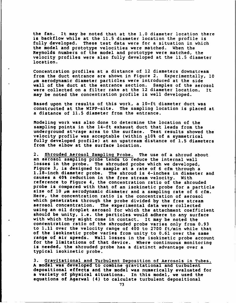
the fan. It may be noted that at the 1.0 diameter location thereis backflow while at the 11.5 diameter location the profile isfully developed. These test data were for a situation in whichthe model and prototype velocities were matched. When theReynolds numbers of the model and prototype were matched, thevelocity profiles were also fully developed at the 11.5 diameterlocation.
Concentration profiles at a distance of 12 diameters downstreamfrom the duct entrance are shown in Figure 2. Experimentally, 10pm aerodynamic diameter particles were introduced at the sidewall of the duct at the entrance section. Samples of the aerosolwere collected on a filter rake at the 12 diameter location. Itmay be noted the concentration profile is well developed.
Based upon the results of this work, a 10-ft diameter duct wasconstructed at the WIPP-site. The sampling location is placed ata distance of 11.5 diameter from the entrance.
Modeling work was also done to determine the location of thesampling points in the 14-ft exhaust duct that leads from theunderground st-rage area to the surface. Test results showed thevelocity profile was acceptable (within ±10% of a symmetricalfully developed profile) at an upstream distance of 1.5 diametersfrom the elbow at the surface location.
2. Shrouded Aerosol Sampling Probe. The use of a shroud aboutan aerosol sampling probe tends to reduce the internal walllosses in the probe. The shrouded probe which we developed,Figure 3, is designed to sample at a rate of 6 cfm through a1.18-inch diameter probe. The shroud is 4-inches in diameter andcauses a 40% reduction in the free stream velocity. Withreference to Figure 4, the concentration ratio of the shroudedprobe is compared with that of an isokinetic probe for a particlesize of 10 pm aerodynamic diameter and a sampling rate of 6 cfm.Here, the concentration ratio is the concentration of aerosolwhich penetrates through the probe divided by the free streamaerosol concentration. The experimental data were collectedusing an oil droplet aerosol for which the attachment coefficientshould be unity, i.e. the particles would adhere to any surfacewith which they might come in contact. It may be noted theconcentration ratio of the shrouded probe varies only from 0.93to 1.11 over the velocity range of 400 to 2700 ft/min while thatof the isokinetic probe varies from unity to 0.61 over the samerange of air speeds. Wall losses in the isokinetic probe accountfor the limitations of that device. Where continuous monitoringis needed, the shrouded probe has a distinct advantage over atypical isokinetic probe.
3. Gravitational and Turbulent Deposition of Aerosols in Tubes.A model was developed to combine gravitational and turbulentdepositional effects and the model was numerically evaluated fora variety of physical situations. In this model, we used theequations of Agarwal (4) to calculate turbulent depositional
73
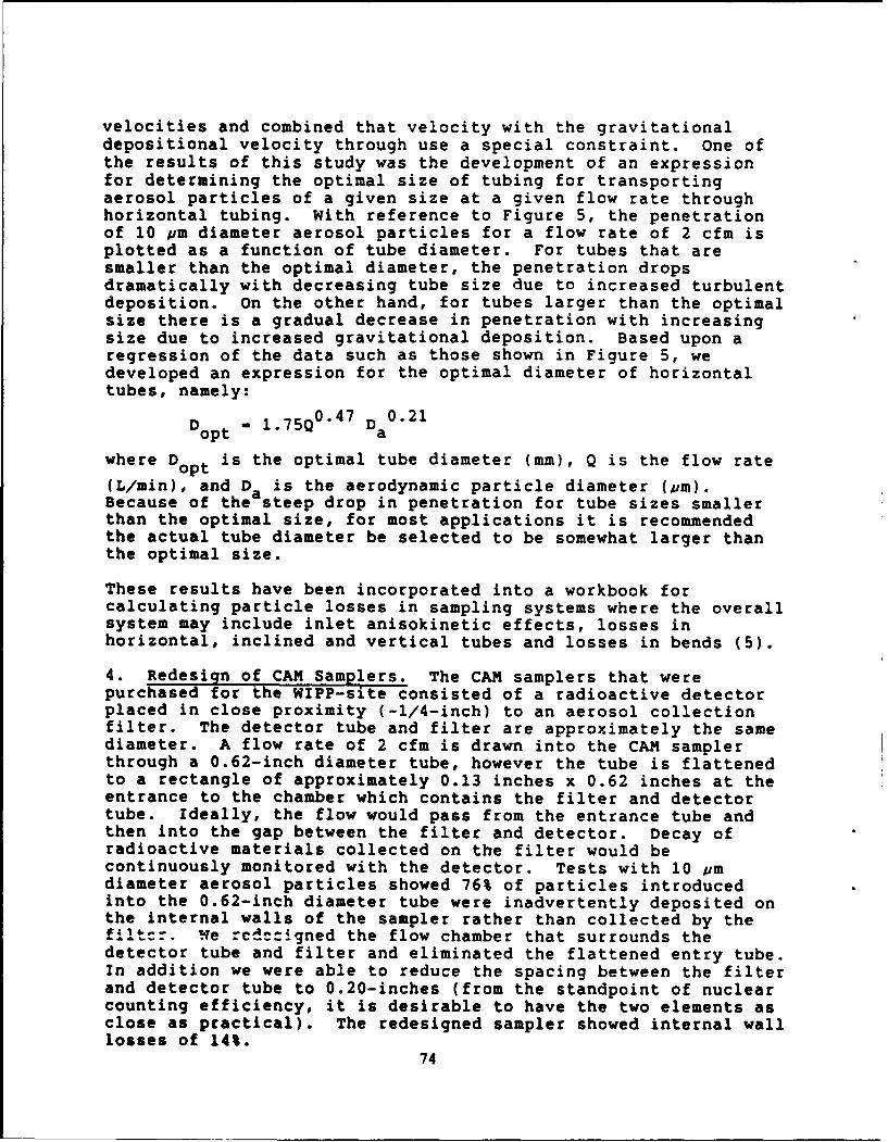
velocities and combined that velocity with the gravitationaldepositional velocity through use a special constraint. One ofthe results of this study was the development of an expressionfor determining the optimal size of tubing for transportingaerosol particles of a given size at a given flow rate throughhorizontal tubing. With reference to Figure 5, the penetrationof 10 pm diameter aerosol particles for a flow rate of 2 cfm isplotted as a function of tube diameter. For tubes that aresmaller than the optimal diameter, the penetration dropsdramatically with decreasing tube size due to increased turbulentdeposition. On the other hand, for tubes larger than the optimalsize there is a gradual decrease in penetration with increasingsize due to increased gravitational deposition. Based upon aregression of the data such as those shown in Figure 5, wedeveloped an expression for the optimal diameter of horizontaltubes, namely:
Dopt - 1.75Q04 7 Da 0.21
where D is the optimal tube diameter (mm), Q is the flow rateopt
(L/min), and Da is the aerodynamic particle diameter (pm).Because of the steep drop in penetration for tube sizes smallerthan the optimal size, for most applications it is recommendedthe actual tube diameter be selected to be somewhat larger thanthe optimal size.
These results have been incorporated into a workbook forcalculating particle losses in sampling systems where the overallsystem may include inlet anisokinetic effects, losses inhorizontal, inclined and vertical tubes and losses in bends (5).
4. Redesign of CAM Samplers. The CAM samplers that werepurchased for the WIPP-site consisted of a radioactive detectorplaced in close proximity (-1/4-inch) to an aerosol collectionfilter. The detector tube and filter are approximately the samediameter. A flow rate of 2 cfm is drawn into the CAM samplerthrough a 0.62-inch diameter tube, however the tube is flattenedto a rectangle of approximately 0.13 inches x 0.62 inches at theentrance to the chamber which contains the filter and detectortube. Ideally, the flow would pass from the entrance tube andthen into the gap between the filter and detector. Decay ofradioactive materials collected on the filter would becontinuously monitored with the detector. Tests with 10 pmdiameter aerosol particles showed 76% of particles introducedinto the 0.62-inch diameter tube were inadvertently deposited onthe internal walls of the sampler rather than collected by thefilter. le rcdctigned the flow chamber that surrounds thedetector tube and filter and eliminated the flattened entry tube.In addition we were able to reduce the spacing between the filterand detector tube to 0.20-inches (from the standpoint of nuclearcounting efficiency, it is desirable to have the two elements asclose as practical). The redesigned sampler showed internal walllosses of 14%.
74
ACKNOWLEDGMENT
Funding for this research was provided by the U.S. Department ofEnergy, WIPP Project Office under Contract DE-AC04-86AL31950 toWestinghouse Waste Isolation Division. Westinghouse, in turn,funded us under Subcontract No. 94-WLM-26907-SD. We wish tothank Mr. Kevin J. Shenk of Westinghouse for his helpfulsuggestions during the course of this work.
REFERENCES
1. Air Movement and Control Association, Inc. (AMCA). FanApplication Manual - Fan and Systems. AMCA Publication 201.AMCA, Arlington Heights, IL. (1985).
2. Parker, J.D., J.H. Boggs and E.F. Blick. Introduction toFluid Mechanics and Heat Transfer. Addison-Wesly Publishing Co.,Inc., Reading, MA. (1969).
3. Incropera, F.P. and D.P. DeWitt. Fundamentals of Heat andMass Transfer. Second Ed. John Wily and Sons, New York.(1985).
4. Agarwal, J.K. Aerosol Sampling and Transport. Ph.D. Thesis.University of Minnesota, Minneapolis. (1983).
5. Anand, N.K. and A.R. McFarland. Particle Penetration throughCAM-Sampler Aerosol Transport Lines. Report No.5897/01/01/88/NKA, Aerosol Technology Laboratory, Department ofMechanical Engineering, Texas A&M University, College Station,TX. (1988).
75
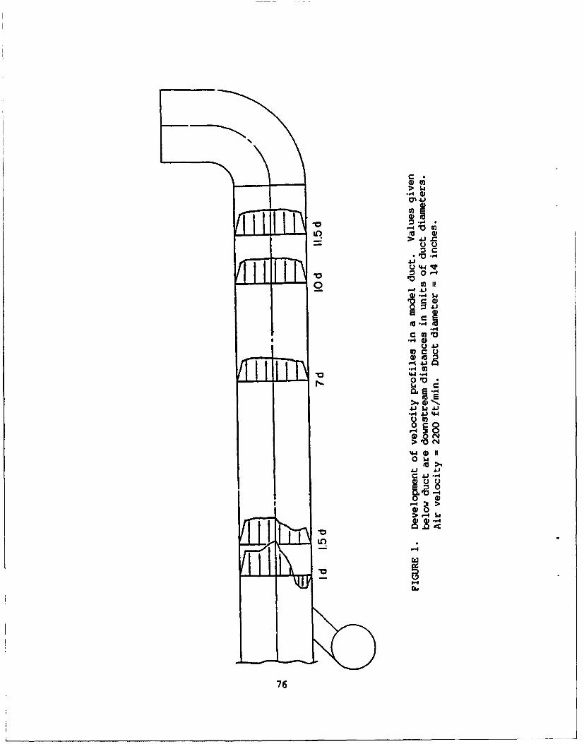
CA
-4J0
I
o021
.. 4
..q 0
V0 'G.'s
0.0V
5. J 44
>9 a) '* .
JJ$JJ-8
0~.
C 4J.-
>-4 L
(zo
76
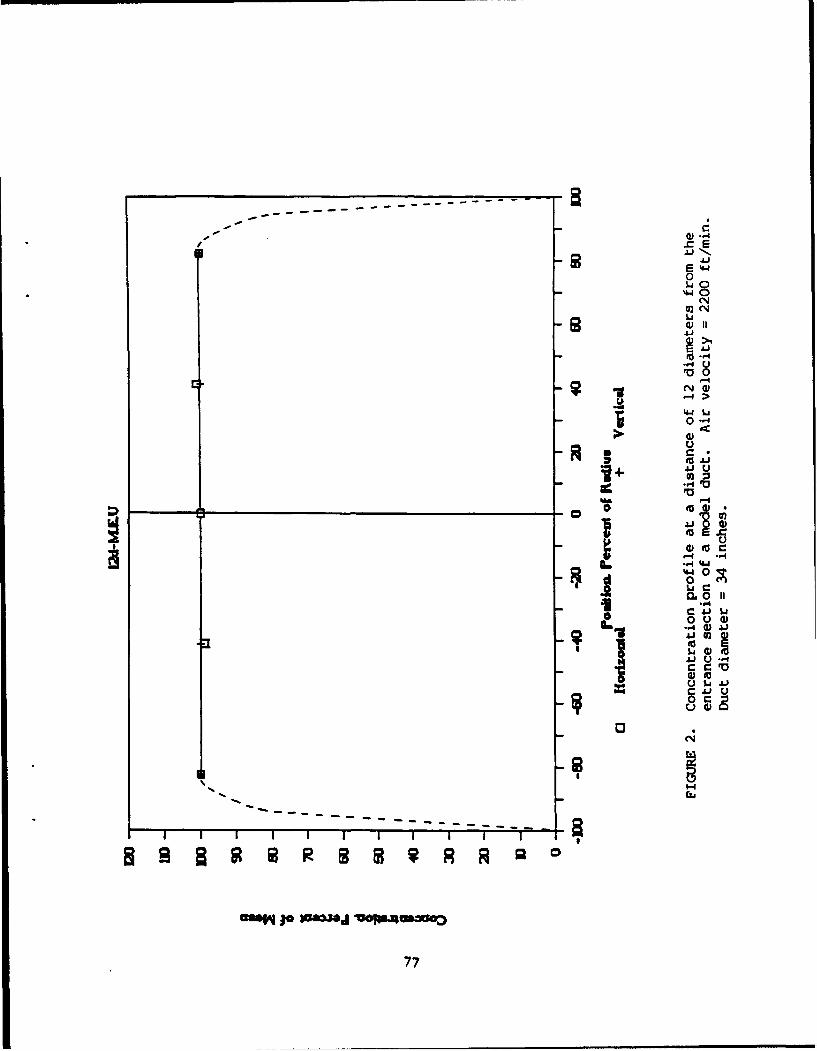
.L)
0
44
0
0
4JU
4J
44 0
- "4
U
0.31
MM~~ ~ ~ ~ ~ Sa*Ij 6L=6aG
77- 0J
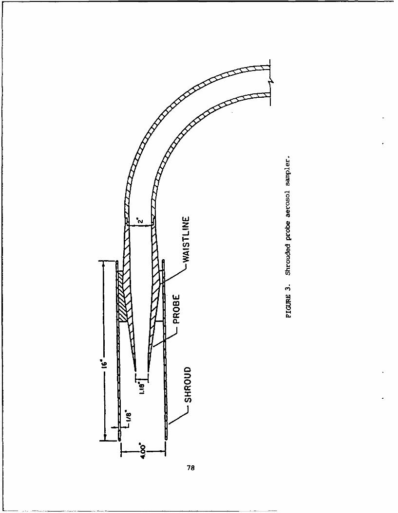
-cy4
00cU)
00
00cr.i
782
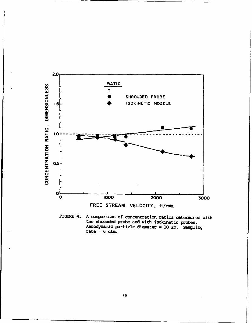
2.0
RATIO(I) T
z SHROUDED PROBE0Ui 1.5- ISOKINETIC NOZZLEzw
0
z
z
0
0 1000 2000 3000
FREE STREAM VELOCITY, ft/min
FIG=R 4. A comparison of concentration ratios determined withthe shrouded probe and with isokinetic probes.Aerodynamic particle diameter = 10 urn. Samplingrate = 6 cfm.
79
1.0
LENGTH
0.8- 5 ft.
2 0.6-
F- 1a:I-
-1-0.2S
#--40
0
TUBE INSIDE DIAMETER, in.
FIGURE 5. Penetration of aerosol particles throughhorizontal tubes with circular cross sections.Aerodynamic particle diameter = 10 pmn.
80
Optical Properties of Smoke Agglomerates
George Mulholland, Nelson Bryner, and Raymond MountainNational Institute of Standards and TechnologyGaithersburg, Md 20899
Light scattering has recently been used to determine the fractal dimension,df, of clusters of particles formed into agglomerates. The usefulness of thefractal dimension is that it makes it possible to concisely characterize a setof statistically similar, but geometrically irregular objects. Here wepresent results on the scattering properties of agglomerates grown viacomputer simulation and also report preliminary experimental results on theoptical properties of "fresh" and cloud processed smoke.
Theor:ZThe agglomerates are generated using a simulation method which mimics theprocess of agglomeration which occurs when diffusing primary particles sticktogether forming an irregular mass. We begin a simulation by distributing4,000 primary particles at random positions in a cubic box which is subject toperiodic boundary conditions. The diffusive motion of a particle of mass m isdescribed by the Langevin equation. The diffusive motion of the particle issupplemented by the condition that if any two primary particles touch, theystick forming a larger, rigid cluster. This cluster continues to diffuseaccording to the Langevin equation but with a changed mass. This -rocesscontinues until clusters ranging in size from 10 - 700 primary units areformed. This growth process is known in the fractal literature as cluster-cluster aggregation.
Once the set of agglomerates has been generated, the V-V scattering intensityis calculated using the Rayleigh-Debye theory in which each primary particleacts as a dipole source for scattered radiation. It is the difference inphase of the light scattered from the separate primary particles thatdetermines the overall scattered field. The scattering cross section, a, isobtained as
a - C IZexp(iq'r,)1 2 - C S(q),
where S(q) is the structure factor of the cluster and the coefficient C is afunction of the wavelength of light and the polarizability of the primaryparticle. The quantity q is the standard momentum transfer vector withmagnitude given by IqI - (4ff/A)sin(8/2), where A is the wavelength and 8 thescattering angle.
The orientation averaged structure factor is defined as I(q). The entire setof I(q) curves for 48 clusters ranging in size from 10 - 700 primary particlescan be correlated when the results are plotted as I(q)/N 2 vs Rsq, asillustrated in Fig. 1. The quantity N refers to the number oi primaryparticles in the cluster and R1 is the radius of gyration of the cluster.
The scaling property of these light scattering results indicates that the pairdistribution function for the clusters should be a function of r/R., where ris the distance between a pair of primary particles. That is because the
81
intensity and this function are Fourier transform pairs. That Ra is theproper length scale is illustrated in Fig. 2 where the pair distributionfunctions, G(r/R.), for the set of 48 clusters are plotted in Fig. 2.
ExDerimentTo provide data for testing theories of the optics of fractal clusters and foruse in assessing the potential climatic impact of smoke produced by nuclearweapons initiated mass fires, we have measured the extinction, scattering, andabsorption coefficient of "fresh" acetylene smoke and for cloud processedacetylene smoke. A transmission cell-reciprocal nephelometer similar toGerber's (1982) design was used to measure simultaneously the extinction andtotal scattering coefficient of the smoke. The absorption coefficient wasobtained by subtracting the scattering coefficient from the extinctioncoefficient.
The smoke was produced by burning acetylene in a laminar diffusion burner.The cloud processing of the smoke was performed in a 9 liter scaled-up versionof the Pollak expansion cloud chamber at an over pressure of 160 mm Hg. Asudden expansion produced a cloud of water droplets with the smoke particlesacting as nuclei. The droplets were evaporated, and the "processed" smoke waspassed into the 9 liter optical cell. The light transmission through thecell, the total scattering, both at A-633 nm, and the mass concentration ofthe smoke were measured simultaneously as the cloud processed smoke movedthrough the cell.
The cloud processed smoke is observed by electron microscopy to be morecompact than the "fresh" smoke. The specific scattering cross section, a,, ofthe cloud processed smoke is almost twice as large as that for the freshsmoke, while the specific absorption cross section, a., is not affected by thecloud processing. Both of these results are consistent with the Berry-Percival optical theory for fractal clusters based on an estimated clustersize of about 400 primary particles, each with a diameter of 35 nm.
It is predicted that for cluster with 10,000 or more primary particles, theabsorption and scattering coefficient of the cloud processed soot would be afactor of two less than that for the "fresh" smoke. The implication of thiseffect on the global climatic impact of mass fires initiated by a majornuclear is a topic of much interest.
We would like to acknowledge C.F. Rogers, J.G. Hudson, and J. Hallett fromDesert Research institute, Reno, for constructing the expansion 1hamber andassisting in the experiment.
Gerber, H.E., Light Absorption by Aerosol Particles, ed. by H.E. Gerber andE.E. Hindman, Spectrum Press, Hampton Virginia, 231-241, (1982).
82

10 0
04 + 4
I _.. +
Ow% +; *
+ +
I 4.
+
I 4.
0 ++01 +
+ + +
F. 1 Te s
g enar of g +
Fig. 1a. ue tcle deterinenst o the seattured foght base on8a
exponential cutoff function is represented by the solid line, and the hard
sphere type cutoff function suggested by Hurd and Flower is indicated by the
dashed line. 8
83
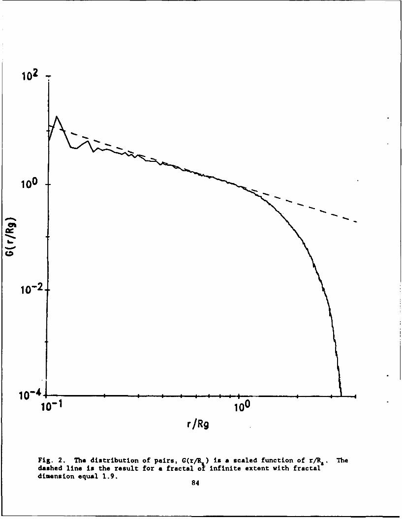
i00
0-4
icr'1 100
r/R9
Fig. 2. The distribution of pairs, G(r/R ) is a scaled function of r/R. Thedashed line is the result for a fractal ol infinite extent vith fractaladimension equal 1.9.
84
AEROSOL MASS CONCENTRATION MEASUREMENTS BY X-RAY FLUORESCENCE
George M. ThomsonU.S. Army Ballistic Research LaboratoryAberdeen Proving Ground, Maryland 21005
ABSTRACT
The Ballistic Research Laboratory has developed two devices formeasuring the mass concentration of aerosols containing elementshaving atomic number Z > 24 appearing as droplets or particles. Whilethe two devices differ in details and in the densities of the aerosolsthey address, both operate on the same principle - x-ray fluorescence(XRF). In XRF one bombards the particles with x-rays of known energy.These primary x-rays ionize the inner shells of any atoms theyencounter, and sometimes cause these atoms to fluoresce; that is, toemit x-rays of their own at lower energies characteristic of theirspecies. If the atomic number Z of the atom is large enough, thefluorescent x-rays can be detected. Their abundance reveals theconcentration of the aerosol and their energy its elemental identity.
The first device is intended for aerosols with low massconcentrations. Prior to irradiation it separates out the particlesby pumping the aerosol at a known adjustable rate (0 - 0.1 cubicmeters/min) through a section of a tape made of filter paper. Motionof the tape is incremented so that each section filters the airstreamfor a fixed period of time. As the tape advances, new sectionsintercept the airstream while exposed sections move before an annular25 mci Cd-109 radioactive source. Here the trapped particles arebombarded with 22 keV x-rays. Those resulting fluorescent x-raysemitted axially to the source annulus pass through its central openingand onto a gas proportional counter. When this occurs, the countergenerates an electrical charge pulse proportional to the energy ofeach impinging fluorescent x-ray photon. Digital circuitry thenascertains the number of photons at each energy detected in thecounting/pumping period - raw data that reveals the abundance of eachindividual qualifying element in the aerosol simultaneously. Notethat the x-ray method is independent of the state of chemicalcombination of the target product and it can sense one, two, or moreelements simultaneously.
The device has been tested and calibrated for over a dozenelements. A summary of its response to some elements often thesubject of worker safety concerns are listed in Table 1. The responseis measured in terms of the minimum level at which the massconcentration can be determined with 10% accuracy in the time cited.The left-hand column shows values of the currently accepted thresholdlimited values for permitted 40 hr week worker exposure.
85
During development of the first detector, it was realized thatthe extremely high sensitivity of XRF held promise for eliminating along-standing problem in dense metal aerosol work - the necessity ofhaving to extract particles out of the air prior to assessment in afashion which gives samples that are truly representative of theaerosol. Accordingly we have designed XRF system that operatesdirectly on the aerosol as dispersed, and provide non-invasiveconcentration measurements rapidly, simply and reliably for mostmaterials with atomic number above 24.
The direct system uses a thermionic x-ray tube in place of aradioisotope to ionize the target. In operation, a flux of x-raysproduced by the tube is sent directly out into the aerosol. Some ofthe x-rays impact upon the metal particles, ionizing them and inducingfluorescence. The characteristic, fluorescent x-rays are thendetected and analyzed by methods similar to that of the first device.
A proof-of-principle monitor has recently been constructed whichincorporates an interchangable anode structure. This feature allowsone to adjust the energy of the primary x-ray flux by proper selectionof an anode material. Using germanium and gold anodes and operatingat 20kV, I ma 'a penetration and power level far less than that of,say, a medical device), XRF was recently employed in tests targeting atwo dimensional simulation of an iron aerosol. The results show thatin a minute or less one can assess mass concentrations from a fewmilligrams up to several grams per cubic meter. It is expected thatwith increased x-ray fluxes and improved spectral purity of theprimary x-rays one can realize better sensitivity, lower minimummeasurable concentrations and more rapid function.
86

TABLE 1.
element min. QUANTITATIVELY MEASUREABLE Permissible concentrationconc., +/- 10% std. dev. 40 hr/wk worker exposure(micrograms/cu. meter) (micrograms/cu. meter)
4 min. sample 10 min. sample
Uranium 24.8 4.0 200 soluble & insoluble
Lead 39.0 6.2 150 inorganic dusts &fumes as Pb
Mercury 27.0 4.3 100 dusts and mists ofinorganic compounds,
Chromates 68.3 10.9 50 Chromium (VI) as Cr;500 Chromium (II) &(III) as Cr; metal
Arsenic 18.3 2.9 200 dusts and mists ofinorganic compounds
Copper 26.2 4.2 200 as fume; 1000 asdusts & mists
Iron 47.7 7.6 1000 for soluble iron saltas Fe; 5000 for Ironoxide fumes as Fe
Zinc 24.4 3.9 5000 for Zinc Oxide fume;10,000 for Zinc Oxide dust
87

Blank
88
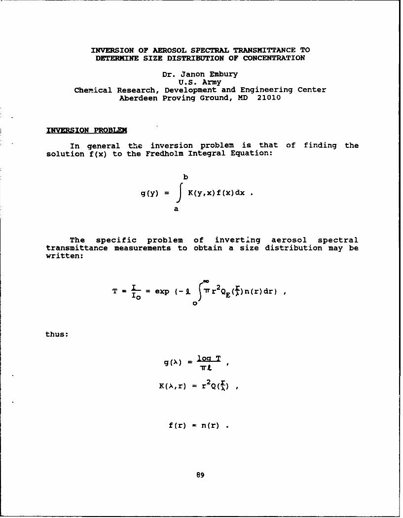
INVERSION OF AEROSOL SPECTRAL TRANSMITTANCE TODETERMINE SIZE DISTRIBUTION OF CONCENTRATION
Dr. Janon EmburyU.S. Army
Chemical Research, Development and Engineering CenterAberdeen Proving Ground, MD 21010
INVERSION PROBLEM
In general the inversion problem is that of finding thesolution f(x) to the Fredholm Integral Equation:
b
g(y) = 9 K(y,x)f(x)dx
a
The specific problem of inverting aerosol spectraltransmittance measurements to obtain a size distribution may bewritten:
T = i = exp (-9. .rS7r2QE()n(r)dr)Io E
0
thus:
g(X) lo oT
K(A,r) = r2 Q(Q)
f(r) = n(r)
89
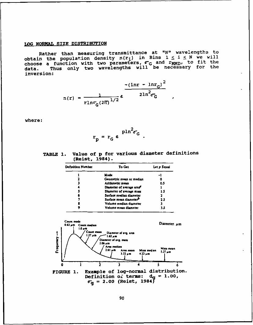
LOG NORNAL SIZE DISTRIBUTION
Rather than measuring transmittance at 'IN" wavelengths toobtain the population density n(ri) in Bins 1 <S i <S N we willchoose a function with two parameters, 4rG and rMMD, to fit thedata. Thus only two wavelengths will be necessary for theinversion:
-(lnr - lnr G) 2
n(r) 1/ 2 1n 2 -Grlno-(2M) 1
where:
rp = rG e l2 r
TABLE 1. Value of p for various diameter definitions(Reist, 1984).
Definition Number To Get Let p Equal
I Mode -12 Geometric mean or median 03 Arithmetic mean 0.54 Diameter of average area' IS Diameter ofaverage mas 1.56 Surface median diameter 27 Surface mean diametezh 2.SI Volume median diameter 39 Volume mean diameter 3.S
Count od0.62 pms Count mnedian imte.u
1.0 PmtCount man Diamneter of avg. afm
Diameter of avg. matn 2.06mm
LrAm mnedian Mm-2.61Pat Areameum Man wadia Ma meani
3.32 Pmo 4.23 ism 3 M
0 I2 3 S 6
FIGURE 1. Example of log-normal distribution.Definition oi terms: dc 1.00,
ag= 2.00 (Reist, 1984)'
90
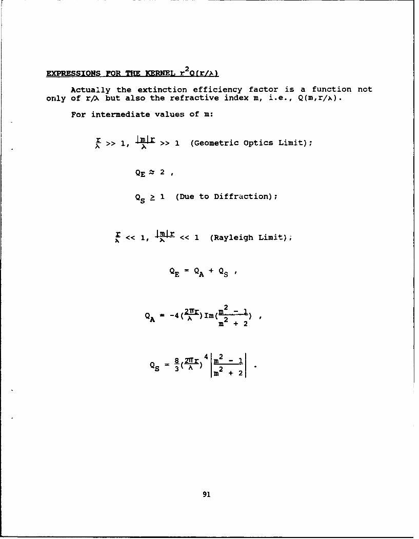
EXPRESSIONS FOR THE KERNEL r 2(r/)
Actually the extinction efficiency factor is a function notonly of r/A but also the refractive index m, i.e., Q(m,r/x).
For intermediate values of m:
>> 1, >> 1 (Geometric Optics Limit);
QE 2 2
QS k 1 (Due to Diffraction);
r << I << 1 (Rayleigh Limit);
QE = QA + QS
A -( m2 + +2
Q 8( T~ )4m2 - 1S 3 Im~ 2 + 2
91

EXPRESSIONS FOR THE KERNEL (continued)
For refractive index near one Im - 11 << 1:
arbitrary, - << 1 (Rayleigh-Gans Limit);
QA= - 4 ( A )Im(m2 +2
QS m - 2 + 2x 2 sin4x 7 (1 - cos4x)S2 -4x 1x2
+(__ _ 2)(V + log4x +J cosu du)
2x x
where:
x - 2 r ;
>> 1, = arbitrary (Anomalous Diffraction);' A
-ftan cos sin( f-13)QE = 2 - 4 r
- tn OA2 cosA2
-4 e pn(c6 cos(P- 2/s) + 4 (p) cos2
where:
m-n- ik
tanp= (n - 1)
= T(n - 1)92
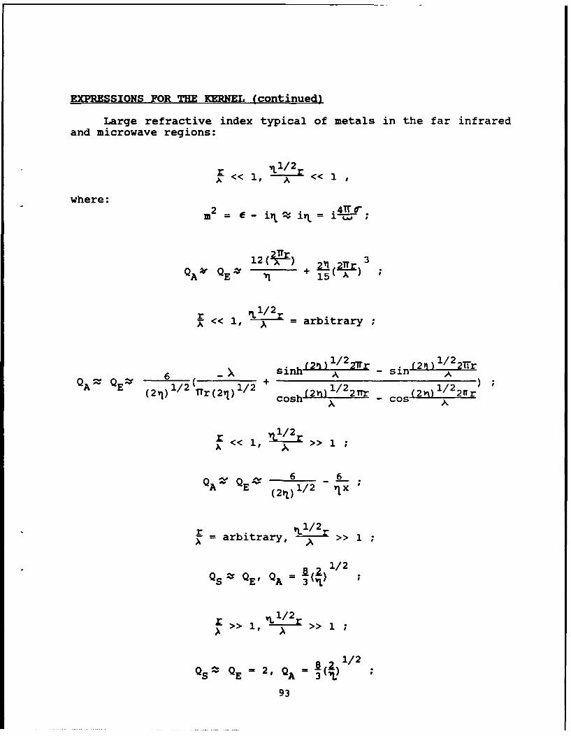
EXPRESSIONS FOR THE KERNEL (continued)
Large refractive index typical of metals in the far infraredand microwave regions:
A<< A << 1
where:
m2 = •- i4 i = i-&-
12 21Tr 3
E 115 A3r
r 1/2rX<< 1, -7- = arbitrary
6-Asinh (2#0 1/2 27r sin (2) 1/2 21ir
Q6 sih A Sl AA QE _ _i/_2 1/2 + 1/2 1/2(2l) 1/ r (21) cosh (2i) 2r C (2v) 2fr
os - cos
A <<i, 1/2r< >> 1;
QA QE 6 _ 6( 2 q) 1/2 vIx
r -arbitrary, 1 / 1 ;
Q - Q=8 ) 1/2QS E' QA 3 3(L)
I >> 1 , >> 1;A ' A
1.2]/2
QS E = 2, QA= 3
93

TABLE 2. Boundary regions of the m-x domain.(van de, Huist, 1957).
Neswa - Mn-1 x(M-I) Chapke or Srn1m ZZUaStUas FOMIAnl
61 a 0 a Q(2l7)r- 0601 W6 8 a 7.2 (Uaykigh.GOW
23 1 Q=2~m1)u
24 5 1 1 Q=24 mr I 1 10.6 (bwai mifat"W)
48 a I Q Q- (0I2)MA* S W6 10.S (OptSca ftaea.)84 I a i(8/20.4
* a 6 6.3 (Rajyuig s in agd)
0 23
22m3
FIGURE 2. Survey of limiting cases in the m-x domain
(van de Huist, 1957).
94
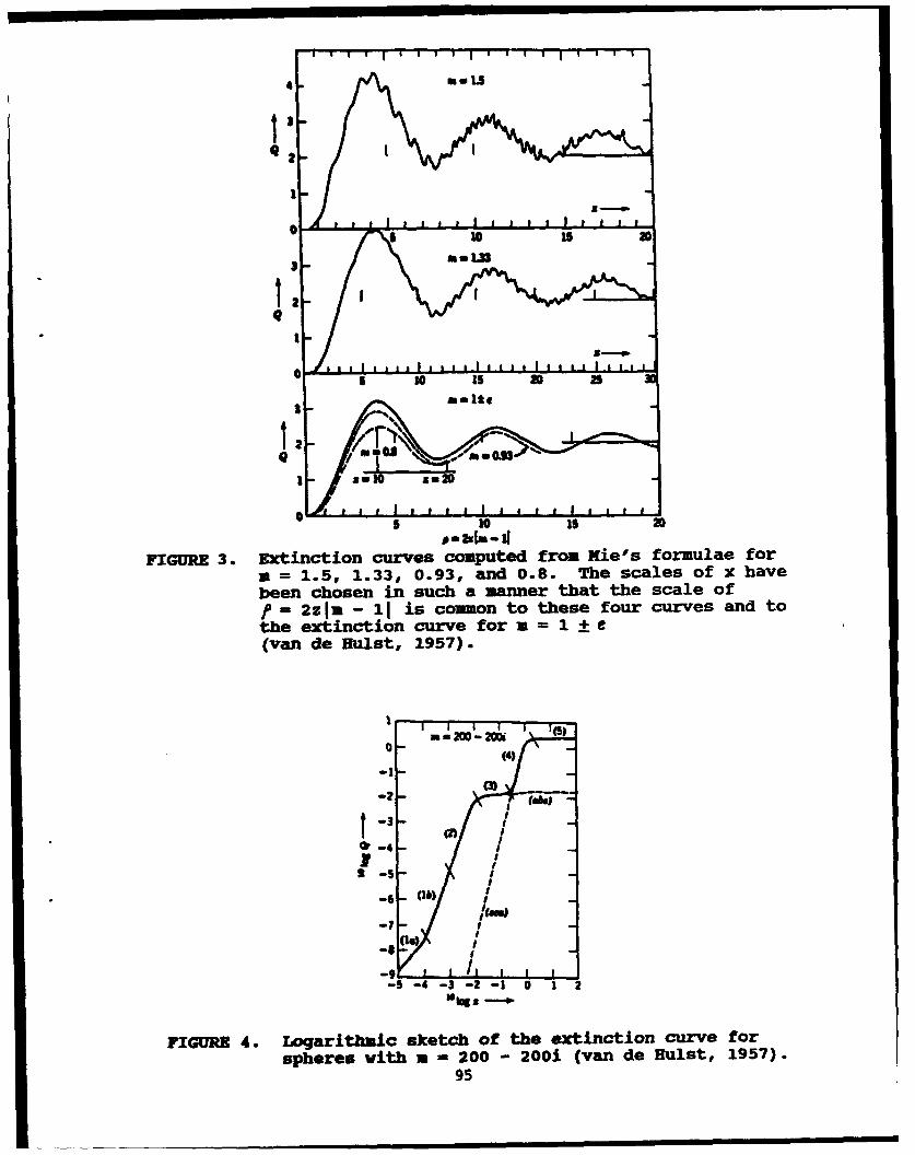
3 In
5 10 i s 3
ismm UI
FIGURE 3. Extinction curves computed from Niel's formulae fora = 1.5, 1.33, 0.93, and 0.8. The scales of x havebeen chosen in such a manner that the scale off = 2zjm - 11 is common to these four curves and tothe extinction curve for a - 1I(van de Huist, 1957).
-lM
(31 -4
-6-ftwo
-7 I
3 5 -4 - 2 Lowe
FIGURE ~ ~ ~ -4.b Loaihi ktho heetnto uv o
spers it a- 00- 20 vnd us,15)-95
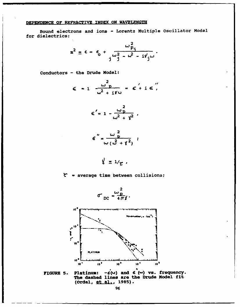
DEPENDENCE OF REFRACTIVE INDEX ON WAVELENGTH
Bound electrons and ions - Lorentz Multiple Oscillator Modelfor dielectrics:
2
i )
Conductors - the Drude Model:
=1 2 + C + ie
2
+ + v2
2+ y2
=average time between collisions;
2
"DC 4 4frY
- ~ ~~VO G- Wi-.. "I
10E 4
to ' ie!,
2 2t
PLAT IN "
~+, ")
to 10 to t01 10* 0
FIGURE 5. Platinum: -() and i vs. frequency.
The dashed lines are the Drude Model fit(Ordal, et. al, 1985).
96
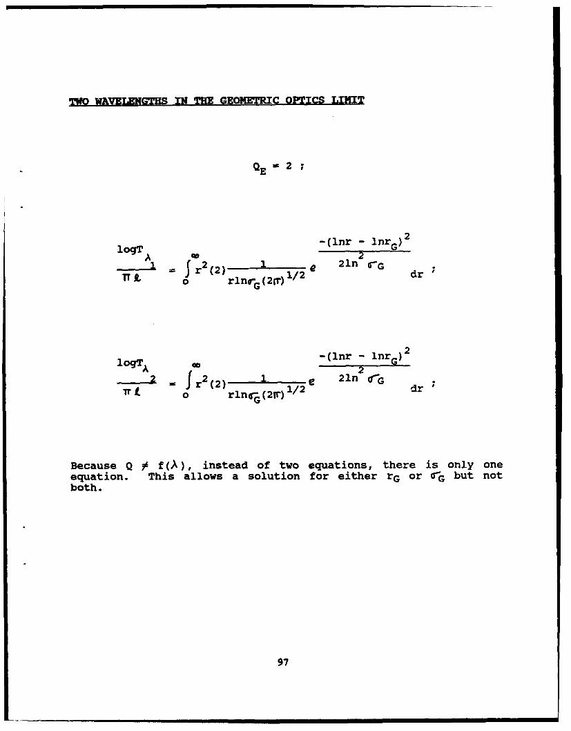
TWO WAVE LNGTHS IN THE GEOMETRIC OPTICS LIMIT
QE=2 ;
22-(lnr - nr G )2
r2(2) 21n CGIT L r G ((2) 1/2 dr
222 r 2 r ( 2 ) 1 - e 21n2 oIG
7ro rln G (21r) 1/ 2 dr
Because Q ' f (A), instead of two equations, there is only oneequation. This allows a solution for either rG or rG but notboth.
97
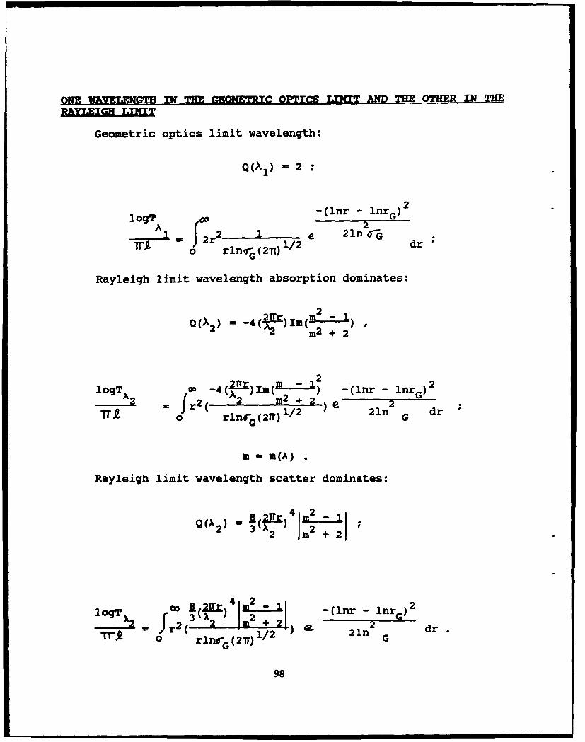
ONE WAVELNU-TH IN THE G=- WRC OPTICS LINMT AND THE OTHER IN THEMYLEIGH LIMIT
Geometric optics limit wavelength:
Q(A1) = 2
2 ;
2 -(lnr - lnrG)
A (21L 2r2 e 21n 6-G
o rlnor (2-n) 1/2 dr
Rayleigh limit wavelength absorption dominates:
2) 3;-) m2 + 2•- !06 211r 2 1
lgTA 2r(-4(A2 )Im( -+2 -(lnr - lnrG)ITir = Jr2( 2 m2 +2 2
T.Q. 0 rlnfG(21r) 1 / 2 21n G dr
m = m(A)
Rayleigh limit wavelength scatter dominates:
4) 2 2 2
loT 2 O 8-(nr- InrG)2
3~ 22rS 2 Im2 + 21),,29T = ri( rlGn; (27r) 1/2 ") 21n2 G d
98
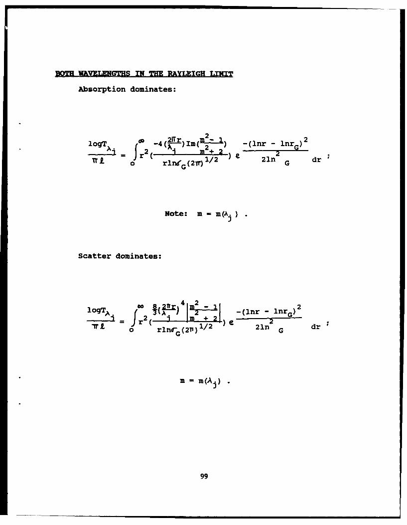
BOTH WAVELENGTHS IN THE RAYLEIGH LIIT
Absorption dominates:
IogT~j OD 2 -4( 2)I m ( ) -(inr lnrG)2
r T2 ( m2 ) 21n dr
0~t rl"G (2Tr) 2
Note: m = m(Aj )
Scatter dominates:
_ 2\1 3 2 -(nr-2flrG)
loqT~j _ r2 m+22
oW 0 rlnE.G(2P )1/2 21n G dr
m =m(Aj)
99
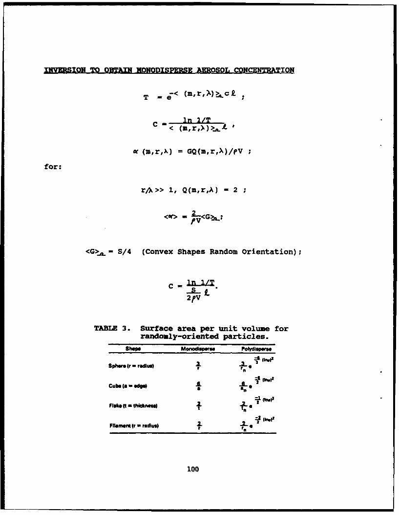
INVERSION TO OBTAIN MONODISPERSE AEROSOL CONCENTRATION
T= j - < (inr,'X)>.cf
In 1/T=<(m,r,>)> L
w (m,r,k) = GQ(m,r,X)/eV
for:
rA>> 1, Q(m,r,A) = 2
<w> 2- GV"-
<G>,,= S/4 (Convex Shapes Random Orientation);
2fV
TABLE 3. Surface area per unit volume for
randomly-oriented particles.
Shape Monodispere Polydisperse
Sphere ,r - rad u ,3. 1r rn
± (~w)2
c , ,=, .2. C_
Fa ameiw - 2
100
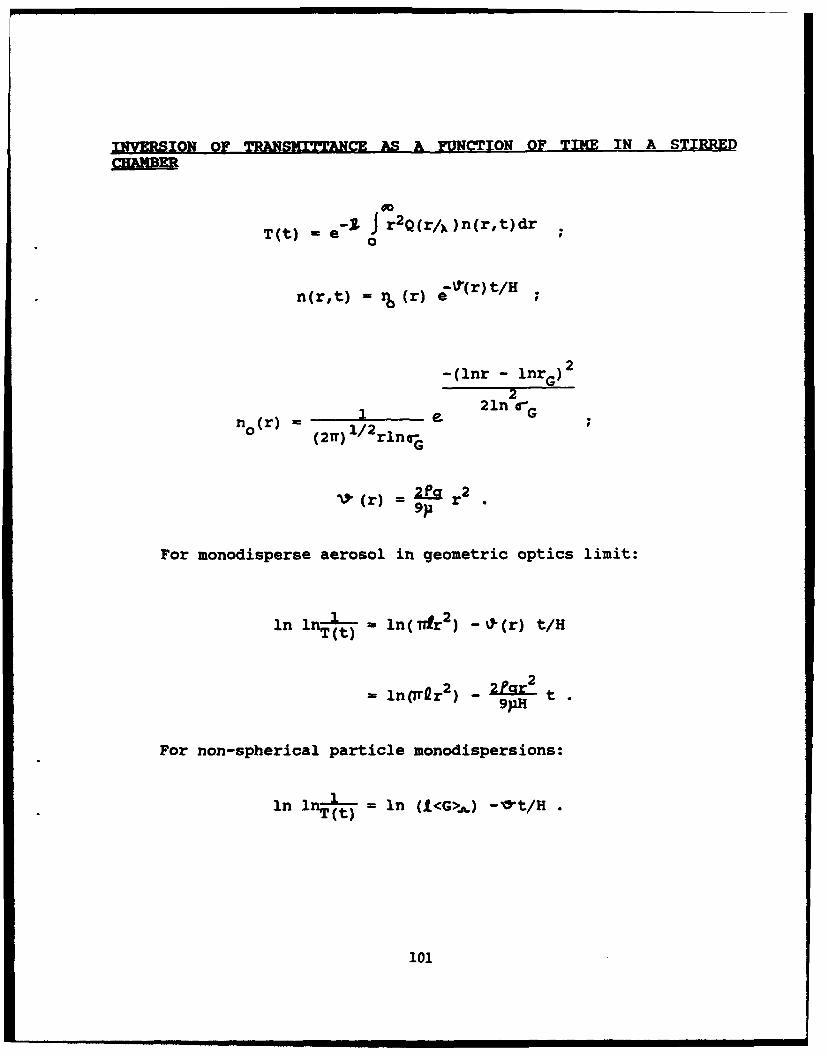
INVRSION OF TRANSMITTANCE AS A FUNCTION OF TIME IN A STIRRED
T(t) - e"' J r 2 Q(r/,)n(r,t)dr0
n (r, t) =%(r) .~(~/
-(lnr - lnr G)2
2(r) = 2121n lfG'G
0 (r) 1 / 2 rln-,
It (r) r
For monodisperse aerosol in geometric optics limit:
in lnT I = in( Tfr 2) - %I-(r) t/H
22
- 1n(Tr~r ) - 9U
For non-spherical particle monodispersions:
in li-t = in (t<G>,..) -m0t/H
101
Ordal, N.A., rta. AD~lied optics, V.124, 4493, 1985.
Reist, P.C., Introduction to Aerosol Science, MacMillan, New York,1984.
van de Huist, H.C., Light Scattering by Small Particles, Wiley,New York, 1957.
102

SECTION IV: PARTICLE CHJLRACTERIZATIONAND APPLICATIONS OF PARTICLE TECHOLOGY
103

Blank
104

An Exercise in Particle Characterization
by J. K. Beddow1153 Engineering Building
University of Iowa, Iowa City, Iowa 52242
IntroductionThe problems associated with the characterization of matter In dividedform have been the subject of increasingly Intensive study during the last40 years.I For much of this time great effort has been devoted to theproblems of measuring particle size. There are now many different methodsfor measuring size all of which are based upon different physical principles.Consequently for non-spherical particles, the vast majority encountered inpractice, each method yields different size data for the same sample.Although this state of affairs Is unwelcome, It Is nevertheless logical.There Is clearly a need for a comprehensive theory that will Include not onlyparticle size, but shape, roughness, symmet' y and many other of thefeatures that collectively constitute the characteristics of the particle orparticle set.
Morphological analysis provides a theoretical framework for this task in thefollowing way:
* It provides an analytical theory and procedures for determiningfeatures including particle size, shape, roughness, symmetry forprofiles, 2-dimensional surfaces, and 3-dimensional particles.2 ,3
* it provides a theory of particle characterization which enables thestandardized set of features to be determined that fullycharacterizes the particle/particle set to the extent desired.4
At the present time particle profile morphological analysis can beconducted to yield size, shape, symmetry, roughness and other measuresusing a newly-available Image analyzer. However, it is not yet possible toconduct a formal particle characterization because the theory Is not quitefinished
This paper describes certain aspects of the theory of morphological profileanalysis. The Image analysis Instrument is then described. Finally, sometypical data are reported.
lorphological AnalysisMorphological Analysis Is the science of the analysis of points In space.Researchers in the multidisciplinary field of particulate science and
105

technology have accessed this science at the microscopic level, Initially intwo dimensions (x,y) and more recently In three dimensions (x,y,z).
Morphological analysis is also applicable to more than three dimensions.For example, (xyz,t).
The essential steps In morphological analysis are:
" determination of the mathematical form of the particlerepresentatior
* extraction of the features from the representations* formulation and ranking of the significant features In order to
characterize the particle or particle set
Once the characterization step Is completed, relationship betweenmorphology and the physical behavior of the particulate material understudy may be sought
Fine Particle RepresentationThe first problem of representation Is the particle profile. It is both thssimplest problem to solve and that from which we learn the most Theshape Is defined as the pattern of relationships among all of the points ofthe profile.
The Initial choice of the (R-e) Fourier method to represent the profile wasarbitrary and expedient. However, the (R-e) method Illustrates the majoraspects which are common to all particle representations. The profileconsists of myriads of (xy) co-ordinate points. The analysis reduces thisx,y, data to an analytical relationship (the Fourier Equation of the Curve).This condensation of information is continued by the extraction of FourierCoefficients. These are transformed Into Invariants. The Invariants thenrepresent the size, shape, and asymmetry of the particle profile. Thesequence of steps Is therefore.
* obtain data that measures the positions of points In space." convert the data to an analytical relationship.* extract coefficients.* transform to Invariant form--these are the features.
The above represents the important steps in morphological analysis.
The morphological variational principle Is the fundamental basis for ageneral theory of morphology:
106
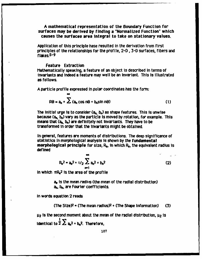
A mathematical representation of the Boundary Function forsurfaces may be derived by finding a "Normalized Function' which
causes the surfaces area Integral to take on stationary values.
Application of this principle hase resulted in the derivation from firstprinciples of the relationships for the profile, 2-D, 3-D surfaces, fibers andflakes.5-9
Feature ExtractionMathematically speaKing, a feature of an object is described In terms ofInvariants and Indeed a feature may well be an invariant This Is Illustratedas follows.
A particle profile expressed in polar coordinates has the form:
Re a I (a cos nB* b+esIn n8) (1)
The Initial urge Is to consider (a. b) as shape features. This is unwisebecause (a, b) vary as the particle is moved by rotation, for example. Thismeans that (a.. ba) are definitely not Invarlants. They have to betransformed In order that the invariants might be obtained.
In general, features are moments of distributions. The deep significance ofstatistics in morphological analysis Is shown by the fundamentalmorphological principle for size, RN, in which R, the equivalent radius isdefined
R 2 -a,.2 + /2 - a.2 + b2 (2)n-t
In which vN2 Is the area of the profile
ao Is the mean radfs (the mean of the radial distribution)aN, b, are Fourier coefficients.
In words equation 2 reads
(The Size)2 - (The mean radius)2 + (The Shape Information) (3)
112 Is the second moment about the mean of the radial distribution, 112 Is
Identical to 2I a,2 + N2. Therefore,
107

RN2 = a 2 + 112 (4)
In words, equation 4 reads,
(The Size)2 - (The Mean)2 + The second moment about the mean (5)
CharacterizationParticle characterization results from a non-simple process of Informationstructuring. Particle characterization Is defined as the communication ofthe description of the essential multidimensional properties of a particleor a collection of particles. Each multidimensional property constitutes acharacterization vecLor which is determined by a measurement vectoroperating on a basis set of the property features. The resultantcharacterization comprises a set of mathematical descriptors and acorresponding set of verbal descriptors.
This theory Is Illustrated by referral to shape characterization In whichC1...Cn are partial rotational symmetries and JI...J2 are partial reflectionsymmetries.
CI CIO C,, C12 CIO aoC2 C20 C21 C22 _ C2 al
a2
C.0 CnC - . (6)O Clo 011 0I 2 -1inC2 (20 C21 022 - 02n
O CnO OnI on2 _ nn an
flsMuWmmt vctw DSis 5.1 ChrInclrlzuUon Vecta
The basis set Is the standard against which all other shapes of profile arecompared The measurment vector Is obtained experimentally using (for aprofile) the R-0 method. The characterization vector Is derived fromequation 6. The standard figures for compilation of the basis set are:circle, cardold, lemiscate, equilateral triangle, square, pentagon, hexagon.etc.
108
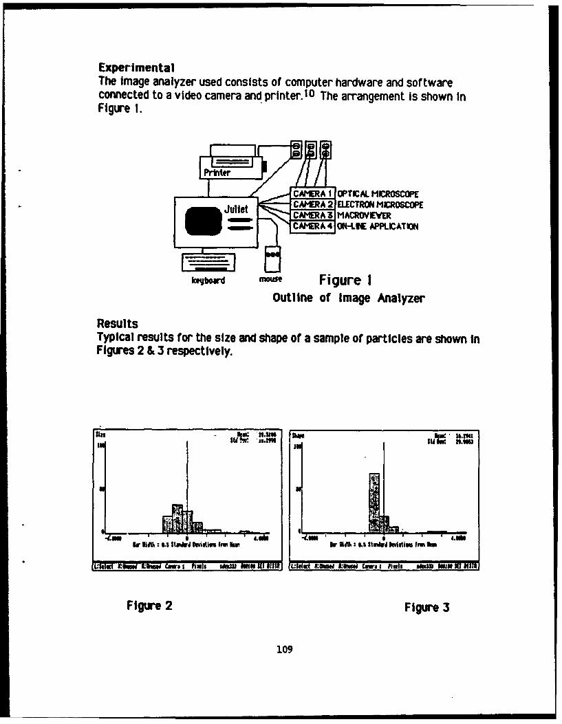
ExperimentalThe Image analyzer used consists of computer hardware and softwareconnected to a video camera and printer. 10 The arrangement Is shown InFigure 1.
JulietCAMERA 2 ELECTRON MICROSCOPE
- CAM~ERA 4 ON-LINE APPLICAT ION
k~jboard Fgr
Outline of Image Analyzer
ResultsTypical results for the size and shape of a sample of particles are shown inFigures 2 & 3 respectively.
I 1
References
I. Beddow, J.K, Particulate Srience and Technolog, ChemicalPublishing Co. New Yorkc, 1980.
2 Luerkens, D.W., OThB R-Theta method derived from a variationalprinciple.", Particulate Scengce and Technology Vol. 4, No. 4, p.353-361, 1986
3. Beddow, J. K, OSIze, Shape and Texture Analysis in Solid/LiquidSystems.w In Recent Advanices In Solid-Liquid Separation ed. H.Muralidhara, Batelle, 1986, pp. 37-6 1.
4 Luerkens, D.W., and Beddow, J.K, ftisions of the Future InMorphological Analysis', to be published In Powder Technoloagy1988.
5. Luerkens, D.W. ilnf Inite Fibers and Threadso, Particulate Sciencesand acbmeWVol 5, No. 3, p. 261-270.
6. Luerkens, D.W., OParticle Surface Morphologies--Flakesu,Particulatg Science and Tachnology. Vol. 5, No. 3, p. 301-309,1987.
7. Luerkens, D.W. Particle Surface Morphologies - Finite Fibers, Part1, Mathematical Description.0 Particulate Science and Techn=LoVol. 5, No. 2, p. 151-160.
8. Luerkens, DAW, OTho Three Dimensional Particle" - Particulate-Scieance and Tchnolgoy Vol. 4, No. 4, p. 371-378, 1986.
9. Luerkens, D.W.. OThe A-Theta Method Derived from a VariationalPrinciple.0, PActiculate Science and Technolog Vol. 4, No. 4, p.361-371, 1986
10. The Shapespeare Corporation, JulietO A Technical Manual IowaCity, Iowa, 1988
110

"Particle-Sizing Reference Materials from the National Bureau of Standards"
Thomas R. LettieriNational Bureau of Standards
Gaithersburg, MD 20899
Abstract This paper summarizes the Standard Reference Materials availablefrom the National Bureau of Standards for use in particle-sizingapplications.
Introduction: The NBS/ASTM Particle SRMs Program
There are many areas of science and technology in which particulatematerial plays an important role; in most cases, some measure of the size ofthe particles is needed. Although there are many different kinds ofinstruments which can give the desired information about the particles, theyall must be referenced to either a well-established physical model or to awell-characterized calibration artifact. Only with such standards canmeasurement uniformity and reproducibility be attained throughout thelaboratory and, on a larger scale, throughout the country.
In order to promote uniformity in particle-size measurement, theNational Bureau of Standards (NBS), under the guidance of an ASTM specialcommittee, has developed a number of Standard Reference Materials (SRMs) foruse in particle-sizing applications [1,2,3,4]. The particle-sizing SRMscertified by NBS can be grouped into two categories: broad-distributionglass beads and monosized polystyrene spheres. Given in the present paperis. a summary of the particle-sizing SRMs currently available from NBS.
Broad-Distribution Glass-Bead SRMs
The broad-distribution glass-bead SRMs available from NBS are summarizedin Table 1. As the Table indicates, the particles have a wide range ofdiameters, from 8 to 2160 pm. Photographs of particles from two of theseSRMs, #1003 and #1019a, are given in Figs. I and 2, respectively. [Asevidenced in the figures, the larger particles tend to be more sphericalthan the smaller ones.]
All of the glass-bead SRMs are certified using optical photomicroscopy,with a well-calibrated microscale used as the dimensional standard. Withthe purchase of each glass-bead SRK, the user gets a certificate ofcalibration which gives information about the distribution of particlediameters; a typical curve of volume distribution, for SRM 1003, ispresented in Fig. 3. The certificate also discusses the application of theglass beads in the calibration of the effective opening of wire-clothsieves.
Although the biggest application, by far, of the broad-distribution glassbeads has been in the calibration of sieves, they have also found use in thecalibration of electrical-sensing zone instruments ("Coulter counters"),optical-sensing zone instruments, forward light scattering instruments,sedimentation devices, and other instruments which measure broad particle-size distributions.
111
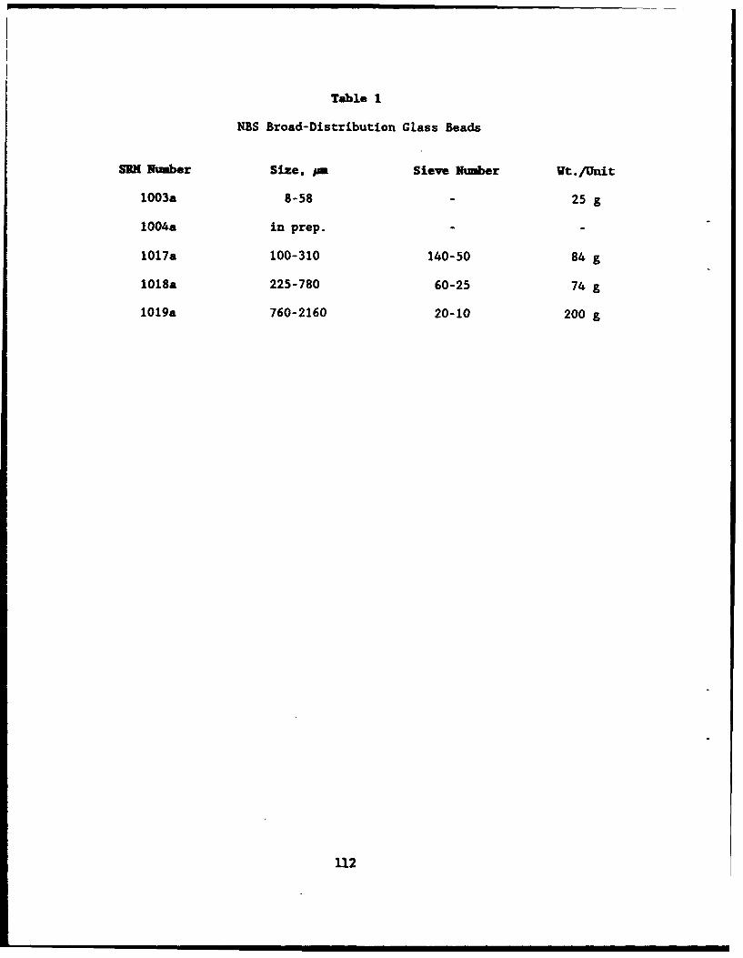
Table 1
NBS Broad-Distribution Glass Beads
SRH Number Size, PE Sieve Number wt. /unit
1003a 8-58 25 g
1004a in prep.
1017a 100-310 140-50 84 g
1018a 225-780 60-25 74 g
1019a 760-2160 20-10 200 g
112
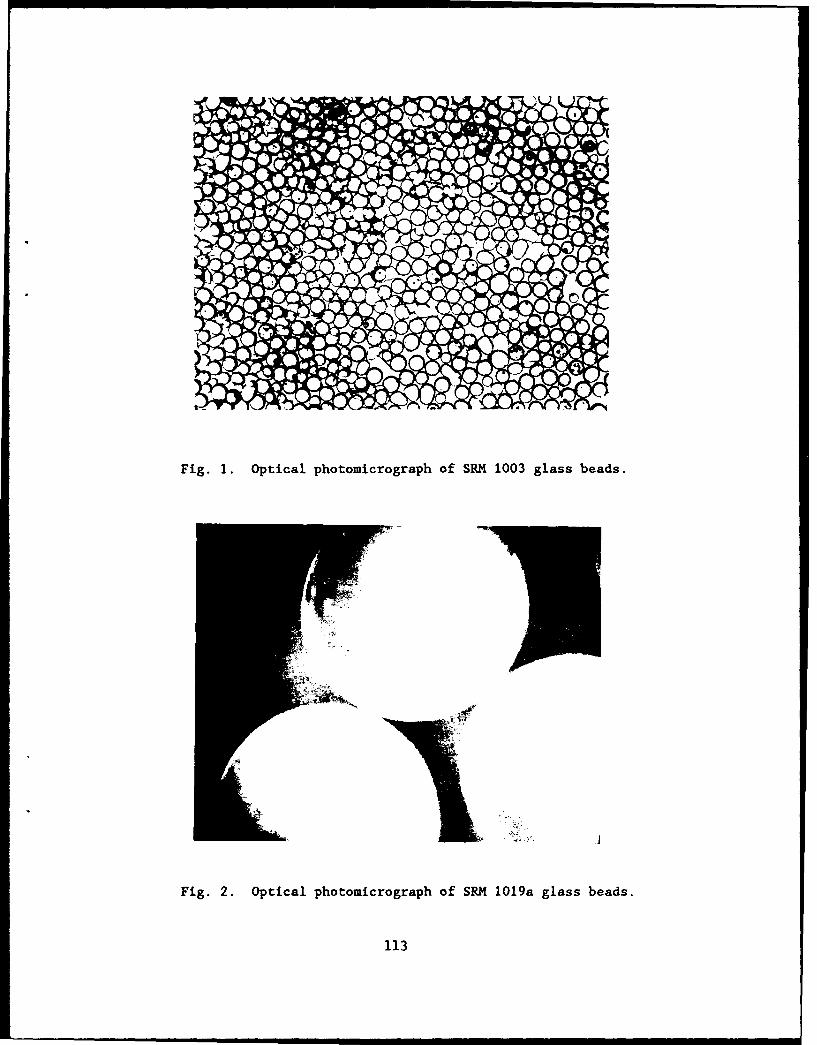
Fig. 1. Optical photomicrograph of SRII 1003 glass beads.
Fig. 2. Optical photomicrograph of SRM 1019a glass beads.
113
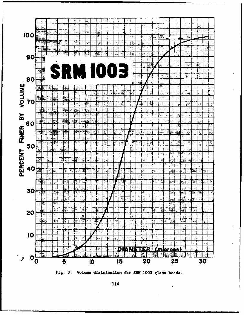
100 - 7 -i - -7-
*Z I
w. - 7: 1: .1 1.:
I~ J I -. I
If1
... .... L. .....
XIYVL"J:iF -Aca~I .~ ~ .. .... -
7 ._
- - .... ... .. A
IK ZI .~ .. ..... H..
20o 5 5 20253
114A
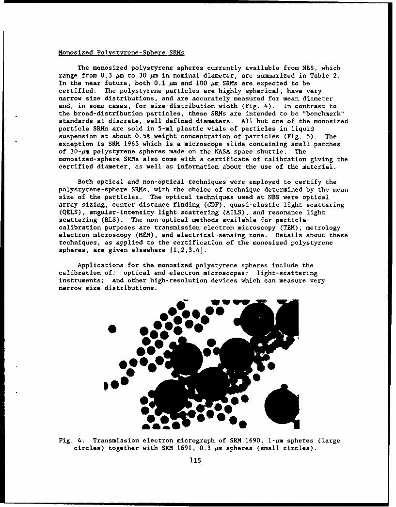
Monosized Polystyrene-Sphere SRMs
The monosized polystyrene spheres currently available from NBS, whichrange from 0.3 pm to 30 pm in nominal diameter, are summarized in Table 2.In the near future, both 0.1 pm and 100 Am SRMs are expected to becertified. The polystyrene particles are highly spherical, have verynarrow size distributions, and are accurately measured for mean diameterand, in some cases, for size-distribution width (Fig. 4). In contrast tothe broad-distribution particles, these SRMs are intended to be "benchmark"standards at discrete, well-defined diameters. All but one of the monosizedparticle SRMs are sold in 5-ml plastic vials of particles in liquidsuspension at about 0.5% weight concentration of particles (Fig. 5). Theexception is SRM 1965 which is a microscope slide containing small patchesof 10-pm polystyrene spheres made on the NASA space shuttle. Themonosized-sphere SRMs also come with a certificate of calibration giving thecertified diameter, as well as information about the use of the material.
Both optical and non-optical techniques were employed to certify thepolystyrene-sphere SRMs, with the choice of technique determined by the meansize of the particles. The optical techniques used at NBS were opticalarray sizing, center distance finding (CDF), quasi-elastic light scattering(QELS), angular-intensity light scattering (AILS), and resonance lightscattering (RLS). The non-optical methods available for particle-calibration purposes are transmission electron microscopy (TEM), metrologyelectron microscopy (MEM), and electrical-sensing zone. Details about thesetechniques, as applied to the certification of the monosized polystyrenespheres, are given elsewhere [1,2,3,4].
Applications for the monosized polystyrene spheres include thecalibration of: optical and electron microscopes; light-scatteringinstruments; and other high-resolution devices which can measure verynarrow size distributions. )WW
Fig. 4. Transmission electron micrograph of SRM 1690, I-Am spheres (largecircles) together with SRM 1691, 0.3-pm spheres (small circles).
115
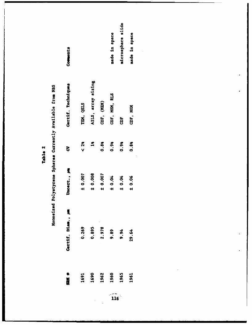
"460
414
C ~ ~ 0 0 01 %
00
"4.
4 00.5.4l C
64L16

WS', P~ 1 c *
Fig. 5. A vial of S 1690 microspheres and a calibration certificate
Future Directions
Among a number of possibilities for future particle-sizing SRMs fromNBS, two important candidates are a "particle-count" standard and a"particle-on-surface" standard. The former is envisioned as a mixture oftwo or more of the monosized polystyrene sphere SRMs, which is thencertified for relative number of particle counts at each of the discretediameters in the mixture. This type of SRM would have many applications,such as setting the vertical scale on a Coulter counter. A particle-on-surface SRM, on the other hand, would be applicable in the measurement ofsurface mcrocontamnaton in such areas as semiconductor processing,optical fabrication, and computer-disc memories. Other possibilities forfuture particle SRMs include opaque particles, aspheres, and cylinders.
Conc lus ion
The Standard Reference Materials certified by the National Bureau ofStandards are intended to be used as primary calibration artifacts bymanufacturers of particle-sizing instruments and by producers of powders andpowder products. In general, the broad-distribution NBS glass beads can beused in everyday production applications, whereas the monosized NBSpolystyrene spheres are not intended for everyday use, since the supplies ofthese materials are limited. For routine, production-line applications, themonosized microspheres sold by several commercial vendors are satisfactory.
Re ferences
[11 G. Mulholland, et. al., J. Res. NBS 90, 3 (1985).
[2] T. Lettieri and G. Hembree, J. Coll. Int. Sei. (to be published, 1988).[3) T. Lettieri, et. al., J. Coll. Int. Soi. (to be published, 1988).[4] T. Letter il of Ota Particle Siznd: Theory and Practice, ed. by G.
Gouesbet and G. Grehan (Plenum, New York, 1988).
117
"particl-nsrae sadr.Tefrmri niind|samxueo

Blank
l18
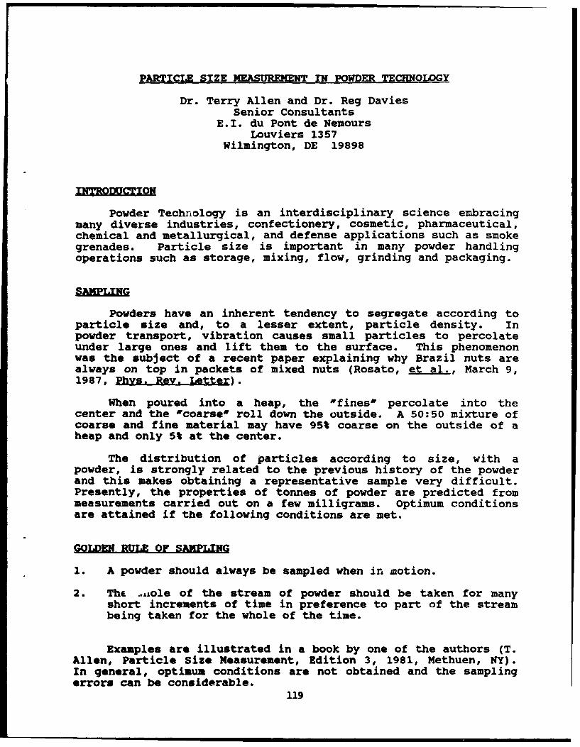
PARTICLE SIZE MEASUREMENT IN POWDER TECHNOLOGY
Dr. Terry Allen and Dr. Reg DaviesSenior Consultants
E.I. du Pont de NemoursLouviers 1357
Wilmington, DE 19898
INTRODUCTI
Powder Technology is an interdisciplinary science embracingmany diverse industries, confectionery, cosmetic, pharmaceutical,chemical and metallurgical, and defense applications such as smokegrenades. Particle size is important in many powder handlingoperations such as storage, mixing, flow, grinding and packaging.
Powders have an inherent tendency to segregate according toparticle size and, to a lesser extent, particle density. Inpowder transport, vibration causes small particles to percolateunder large ones and lift them to the surface. This phenomenonwas the subject of a recent paper explaining why Brazil nuts arealways on top in packets of mixed nuts (Rosato, et al., March 9,1987, Phys. Rev. Letter).
When poured into a heap, the "fines" percolate into thecenter and the "coarse" roll down the outside. A 50:50 mixture ofcoarse and fine material may have 95% coarse on the outside of aheap and only 5% at the center.
The distribution of particles according to size, with apowder, is strongly related to the previous history of the powderand this makes obtaining a representative sample very difficult.Presently, the properties of tonnes of powder are predicted frommeasurements carried out on a few milligrams. Optimum conditionsare attained if the following conditions are met.
GOLDEN RULE OF SAMPLING
1. A powder should always be sampled when in motion.
2. The ..,Aole of the stream of powder should be taken for manyshort increments of time in preference to part of the streambeing taken for the whole of the time.
Examples are illustrated in a book by one of the authors (T.Allen, Particle Size Measurement, Edition 3, 1981, Methuen, NY).In general, optimum conditions are not obtained and the samplingerrors can be considerable.
119

PARTICLE SIZE MASURjMT
There are scores of techniques available for particle size(and surface area) measurement and these have generated hundredsof commercially-available equipment. Ten criteria used inequipment selection are:
1. Capital costs versus running cost.
2. Speed of analysis.
3. Ease of operation.
4. Size range.
5. Versatility.
6. Reproducibility.
7. Accuracy, precision, resolution.
8. Servicing.
9. Data presentation.
10. Compatibility with product to be measured.
Size ranges are often classified as (1) submicron,(2) subsieve (1-100 microns), and (3) sieve (100+ microns)although there is considerable overlap. Subsieve powders may bemeasured by one of the following techniques:
1. Gravity sedimentation.
2. Microscopy (image analysis).
3. Field scanning.
4. Stream scanning.
5. Sieving (micromesh sieves).
6. Classification.
GRAVITY SEDIMENTATIO
The standard gravity sedimentation technique is the Andreasenpipet. Approximately 4.5 g of powder is dispersed in 4b0 ml ofliquid (usually water) and allowed to settle out of suspension.At preset times, e.g., 1, 2, 4, 8, 16, 32 and 64 minutes, 10 mlsamples are withdrawn and the weight of powder (w) in the
120

extracted samples determined by drying and weighing. The settlingtimes (t) and heights of fall (h) generate the sizes of thelargest particles in the extracted samples and w is the weightundersize. The prime difficulty with the technique is making up astable, disperse suspension. The method is time consuming, laborintensive and relies on skilled operation, but capital costs arelow and versatility is high.
This technique has been largely replaced by x-raysedimentation so that mass undersize (w) may be determined by x-ray attenuation. Analytical times are reduced by scanning thesuspension to increase the rate of change of the ratio (h/t). Theattenuation of an x-ray beam is related directly to the mass ofparticles in the beam, but no direct relationship holds for alight beam. Gravitational photosedimentation is widely used as a"fingerprintm method for comparison purposes. Several instrumentsare available for use with cuvets to extend the size range down tobelow one micron using a centrifugal field. Disc photocentrifugesused a line-start technique where the suspension is floated on topof a clear liquid.
FIELD SCANNING
Field scanning refers to techniques which directly determinethe size distribution of an assembly of particles. The mostpopular of these are the ones using low-angle laser lightscattering (LALLS) which are used in the 0.1 to 1800 micron sizerange. The Microtrac Small Particle Analyser, for example, willanalyse from 0.1 o 42.2 microns (now increased to 60 microns) in16 size channels and the standard analyser, from 0.7 to 700microns in 20 classes.
The Armco Autometrics instrument uses ultrasonic attenuationto determine size distributions.
STREAM SCANNING
Stream scanning refers to analysers where the particles aresensed and sized, one by one, as they pass through a sensing zone.In the Coulter Counter, an aperture tube is immersed in anelectrolyte containing the powder. The electrical reactanceacross the aperture is measured by two platinum electrodes oneither side of the aperture. An external vacuum draws thesuspension through the aperture and each particle generates apulse according to its particle volume. The pulses are countedand stored and may be recovered in from 16 to 256,000 sizechannels. The size range for each aperture is from 1.5% to 45%of its diameter, and the total range of the technique is from 0.4to 900 microns.
With a light source, a range of options are available. Light
blockage instruments generate a pulse proportional to the
121
geometric shadow of the particle. HIAC/ROYCO manufacture a rangeof analyses operating using this principle. Some instrumentscollect forward-scattered white or laser light; in order toincrease the collected light flux elliptical mirrors or lenses maybe used.
Other instruments collect light scattered at 90 degrees tothe beam direction. This has the advantage of generating aprecise pulse height for each particle size, combined with thedisadvantage of a strong dependence on refractive index.
The Brinkmann Model 2010 scans the sample with a laser beamusing a rotating prisr. The time spent on the particle isinterpreted as particle size.
The Spectrex Prototron also uses a scanning laser, but usesforward light scattering for size determination.
The Lasentec Lab-tec scans with an infrared laser and picksup back-scattered radiation using a stereoscopic system. Particlesize is measured by dwell time on the particle.
The Flow Vision Analyzer is designed for on-line monitoringof a flowing suspension. The light beam is fed to the processline through a fiber-optic cable and the light pick-up is fed tothe detector through an optical cable. A visual display of theflowing suspension may be obtained using a camera and freeze-frame accessory.
CONCLUSIONS
The above comprises a limited description of a few of theinstruments that operate in the 1- to 100-micron size range. TheField-Scanning and Stream-Scanning Instruments are more rapid thansedimentation but usually generate a more ambiguous size. Thetrend is to use these instruments in an on-line or rapid responsemode to continually monitor processes.
122

PREDICTIONS OF A FATE OF A SMALL HETEROGENEOUS DROPLET BASED ON AN ABSORPTION
PATTERN OF THE INCIDENT ELECTROMAGNETIC RADIATION
Marek A. Sitarski
Clarkson University, c/o U.S. DOE / HETC, Morgantown, V.V. 26505
ABSTRACT
Dynamic behaviour of a small multiphase droplet exposed to electromagneticfields, such as laser beams or a high temperature thermal radiation, attractsa considerable interest both from fundamental and applied points of view.Response of the particle to the external perturbation of a magnitude controlledin a wide range of orders provides a valuable information about dynamicproperties of matter very far from the thermodynamic equilibrium. Recentadvances in the laser technology and in the instrumentation for suspending ofsmall particles in optical traps and in electrodynamic balances make possiblean experimental verification of the predicted regimes and magnitudes of theresponse. Applications of this knowledge might also be essential for some ofthe current technologies. Propagation of laser beams and thermal radiationthrough a polluted atmosphere, controlled laser deposition of particles ofadvanced materials, combustion intensification by the radiation inducedsuperfine atomization of colloidal droplets of modern fuels are some of theactual examples.
When the intense radiation field is incident upon a small heterogeneousdroplet its fate depends primarily on the dissipation pattern of theelectromagnetic energy inside the droplet. As compared with homogeneous dropletsthe radiation absorption inside multiphase droplets is especially nonuniformbecause of different absorptivities of the component phases and additionalreflections/refractions at the inner interfaces. The resulting nonuniformsurface temperature of the irradiated droplet accounts for the photophoreticforce, and also formation of hot spots inside the droplet can cause itsdisintegration by explosive boiling of the liquid.
The current progress in computations of 3-dimensional absorption patternsinside heterogeneous droplets by use of the Mie scattering theory applied formultilayered spherical particles and of effective optical constants ofconcentrated colloids by use of the extended Bruggeman theory is presented.The algorithms and computer codes are developed for a monochromatic radiationbeam and for the black body radiation.
The specific computations are performed for two- and three-phase colloiddroplets if micronized coal and soot dispersed in water. The third phase iseither a layer of surfactant at the water-gas interface or water vapor layer atthe coal-water interface. The effect of intensity, size parameter andtemperature of the incident thermal radiation on the processes of photophoresls,explosive boiling, and transient vaporization of the droplets is studied.
123

Blank
124
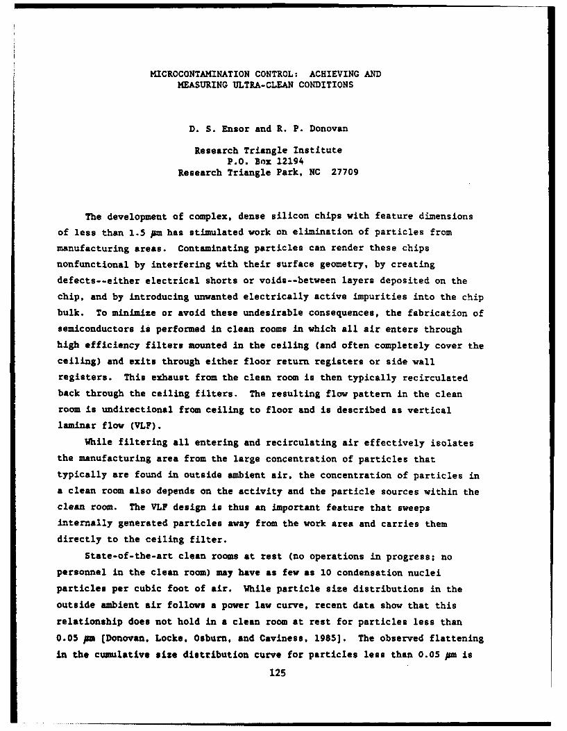
HICROCONTAMINATION CONTROL: ACHIEVING ANDMEASURING ULTRA-CLEAN CONDITIONS
D. S. Ensor and R. P. Donovan
Research Triangle InstituteP.O. Box 12194
Research Triangle Park, NC 27709
The development of complex, dense silicon chips with feature dimensions
of less than 1.5 pm has stimulated work on elimination of particles from
manufacturing areas. Contaminating particles can render these chips
nonfunctional by interfering with their surface geometry, by creating
defects--either electrical shorts or voids--between layers deposited on the
chip, and by introducing unwanted electrically active impurities into the chip
bulk. To minimize or avoid these undesirable consequences, the fabrication of
semiconductors is performed in clean rooms in which all air enters through
high efficiency filters mounted in the ceiling (and often completely cover the
ceiling) and exits through either floor return registers or side wall
registers. This exhaust from the clean room is then typically recirculated
back through the ceiling filters. The resulting flow pattern in the clean
room is undirectional from ceiling to floor and is described as vertical
laminar flow (VLF).
While filtering all entering and recirculating air effectively isolates
the manufacturing area from the large concentration of particles that
typically are found in outside ambient air, the concentration of particles in
a clean room also depends on the activity and the particle sources within the
clean room. The VLF design is thus an important feature that sweeps
internally generated particles away from the work area and carries them
directly to the ceiling filter.
State-of-the-art clean rooms at rest (no operations in progress; no
personnel in the clean room) may have as few as 10 condensation nuclei
particles per cubic foot of air. While particle size distributions in the
outside ambient air follows a power law curve, recent data show that this
relationship does not hold in a clean room at rest for particles less than
0.05 pm (Donovan, Locke, Osburn, and Caviness, 1985]. The observed flattening
in the cumulative size distribution curve for particles less than 0.05 pm is
125
what is predicted from mathematically operating on a typical outside ambient
air size distribution with a typical filter efficiency characteristic [Ensor,
Donovan, and Locke, 1987].
Clean rooms in operation (i.e., not at rest) invariably exhibit short-
term high concentration episodes called "bursts' in addition to a somewhat
elevated stable background concentration. The origin of these 'bursts, are
not completely understood but can result from both human operator sources and
equipment operation. Their existence recommends continuous monitoring at key
positions in the clean room rather than aperiodic site sampling as a
monitoring and control strategy.
Having particles in the clean room is of itself not sufficient to cause
chip failure. The particles must deposit on the chips in vulnerable
locations. The deposition of particles from the gas phase onto surfaces
depends on mechanisms such as gravity, particle diffusion, and convection.
The VLF design and thoughtful equipment layout minimize these mechanisms.
Chip properties such as temperature and electrical charge also affect particle
deposition [Donovan, Clayton, and Ensor, 1987].
Particles can also deposit on a chip during immersion in one of the many
liquid baths to which it is exposed during manufacturing. While gravity is a
much less important deposition mechanism in a liquid bath than in the air,
other properties such as particle and chip hydrophobicity become important and
need to be better understood.
Looming as the most important source of chip contamination at present,
however, is the chip processing equipment itself. Particle emission by chip
processing equipment, including the process chemistry, is now recognized as a
chief sourct, of chip failure, and suppliers of semiconductor processing
equipment must now specify and control the particle concentration in the chip
environment.
Donovan, R. P., A. C. Clayton, and D. S. Ensor. The Dependence of ParticleDeposition Velocity on Surface Potential. Ins 1987 Proceedings of theAnnual Technical Meeting of the Institute of Environmental Sciences, pp.473-478, 1987.
Donovan, R. P., B. R. Locke, C. M. Osburn, and A. L. Caviness. UltrafineAerosol Particles in Semiconductor Cleanrooms. J. Electrochem. Soc.,132(11), pp. 2730-2738, November 1985.
Ensor, D. S., R. P. Donovan, and B. R. Locke. Particle Size Distributions in
Clean Rooms. J. Environ. Sci., 30(6), pp. 44-49, 1987.
126

PARTICULATE CONTROL RESEARCH AND DEVELOPMENT AT EPA
Dr. Norman PlaksEPA
RTP, NC
Particulate control research and development at EPA iscentered around the application of electrostatics in bothelectrostatic precipitation and in fabric filtration. The work inelectrostatic precipitation is concerned with improvingperformance by separating the particle charging and collectionfunctions to allow each to be optimized, thereby providing asignificant increase in performance. Electrified fabricfiltration places a charge upon the particles and then collectsthem on the filtration media, which is in an electric field.Electrification of the fabric filtration process results in both areduced pressure drop and particle penetration. Other work inelectrified fabric filtration improves collection of fibrousparticles, such as asbestos, by first charging the fibers andsubjecting them to an alternating current field at the filtrationsurface, which imparts a vibrational motion causing them to snagon the filter media. Other work is related to the development ofmathematical engineering design models of the electrostaticprecipitation and fabric filtration devices. Other areas ofinterest, which developed from the work on applied electrostatics,are in corona destruction of toxic air pollutants.
127

CONCLUSIONS AND RECOMMENDATIONS
During the past several years, a great deal of progress hasbeen made in the multiple fields associated with fine particletechnology. Perhaps one of the most important of these is therecognition of fine particle research as a significant discipline.Most of this progress has been driven by the semiconductor andclean room processing communities. Significant strides have alsobeen made in the ceramic and composite fields and in filtration.However, there is still much that we need to learn and develop.
One of the major gaps in the state of the art is the problemof high aspect ratio particles. These morphologies pose specificproblems in size distribution measurement. When the significantinformation requires measurements in more than one dimension, andin the same relative dimensions on each particle, all currentmethods fail. This problem is magnified by the difficulty ofseparating such particles from each other, particularly in the caseof long tangled whiskers. Because of this, the additional problemsof dispersing and orienting particles arise. Adding magnetic andelectrical properties to such particles further magnifies theproblem.
Another major concern is the measurement of physicalproperties of individual particles. The traditional problem tophysicists and materials scientists has been growing crystals largeenough to measure. This approach is not applicable for theinformation required for specific applications, and methods areneeded for direct measurement of strengths, conductivities, heatcapacities, etc. of individual particles.
The papers in the Particle Production Section identifynumerous new techniques available for production of controlled sizesubmicron particles of high purity. Further developmental effortis necessary to scale up these techniques to industrial productionwith high output. Submicron particles of narrow size distributionsare needed for advanced ceramics, composites, pigments, and newareas such as high density magnetic recording media.
Particle sampling, measurement and characterization isessential in the areas of smoke dissemination testing, inindustrial process monitoring, and in environmental control ofindustrial emissions in the atmosphere as well as for increasingthe yields of microelectronics devices.
The diversity of the subject and applications of particlesmakes multidisciplinary technology transfer very valuable. Theconsensus of the participants at the Symposium was that suchmeetings are very valuable. We make the following specific
128
recommendations to promote technology transfer:
1. Plan and conduct similar meeting in the future at approximatelytwo-year intervals.
2. Provide more advanced planning period to assure participationby experts.
3. Consider collaboration with other government agencies such asthe National Institute for Standards and Technology, the Departmentof Energy, and the Environmental Protection Agency.
4. Streamline the format of the written contribution to facilitatecompilation of proceedings.
129

Blank
130
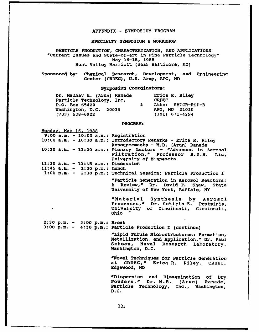
APPENDIX - SYMPOSIUM PROGRAM
SPECIALTY SYMPOSIUM & WORKSHOP
PARTICLE PRODUCTION, CHARACTERIZATION, AND APPLICATIONS"Current Issues and State-of-art in Fine Particle Technology"
May 16-18, 1988Hunt Valley Marriott (near Baltimore, MD)
Sponsored by: Chemical Research, Development, and EngineeringCenter (CRDEC), U.S. Army, APG, MD
Symposium Coordinators:
Dr. Madhav B. (Arun) Ranade Erica R. RileyParticle Technology, Inc. CRDECP.O. Box 65420 & Attn: SMCCR-RSP-BWashington, D.C. 20035 APG, MD 21010(703) 538-6922 (301) 671-4294
PROGRAM:
Monday. May 16. 19889:00 a.m. - 10:00 a.m.: Registration
10:00 a.m. - 10:30 a.m.: Introductory Remarks - Erica R. RileyAnnouncements - M.B. (Arun) Ranade
10:30 a.m. - 11:30 a.m.: Plenary Lecture - "Advances in AerosolFiltration,' Professor B.Y.H. Liu,University of Minnesota
11:30 a.m. - 11:45 a.m.: Discussion11:45 a.m. - 1:00 p.m.: Lunch1:00 p.m. - 2:30 p.m.: Technical Session: Particle Production I
'Particle Generation in Aerosol Reactors:A Review,' Dr. David T. Shaw, StateUniversity of New York, Buffalo, NY
'Material Synthesis by AerosolProcesses,' Dr. Sotiris E. Pratsinis,University of Cincinnati, Cincinnati,Ohio
2:30 p.m. - 3:00 p.m.: Break3:00 p.m. - 4:30 p.m.: Particle Production I (continue)
'Lipid Tubule Microstructures: Formation,Metallization, and Application,' Dr. PaulSchoen, Naval Research Laboratory,Washington, D.C.
'Novel Techniques for Particle Generationat CRDEC,' Erica R. Riley, CRDEC,Edgewood, MD
'Dispersion and Dissemination of DryPowders," Dr. M.B. (Arun) Ranade,Particle Technology, Inc., Washington,D.C.
131

4:30 p.m. - 5:00 p.m.: Discussion: Custom-Made Particles
Tuesday. May 17. 19888:30 a.m. - 9:00 a.m.: Registration9:00 a.m. - 10:00 a.m.: Technical Session: Particle Production II
"Particle Preparation Using AerosolReactions" Dr. Richard E. Partch,Clarkson University, Potsdam, NY
"Colloidal Processes for ParticleProduction,' Drs. Michael E. Mullins,Venugopal B. Menon, RTI, RTP, NC, andM.B. (Arun) Ranade, Particle Technology,Inc., Washington, D.C.
10:00 a.m. - 10:20 a.m.: Break10:20 a.m. - 12:00 p.m.: Aerosol Characterization I
"Aerosol Sampling and Measurement,"Dr. James W. Gentry, University ofMaryland, College Park, MD
'Aerosol Sampling Studies," Drs. DanTurner and Andrew R. McFarland, Texas A&MUniversity, College Station, TX
"Optical Properties of SmokeAgglomeration," Drs. George Mulholland,Raymond Mountain, and Nelson Brynt-r,National Bureau of Standards (NBS),Gaithersburg, MD
12:00 p.m. - 1:15 p.m.: Lunch1:15 p.m. - 2:30 p.m.: Technical S e s s i o n: P a r t i c 1 e
Characterization and Application I
"Morphology of Profiles, Surfaces, andThree Dimensions,N Dr. J.K. Beddow,University of Iowa, Iowa City, IA
"Predictions of a Fate of a SmallHeterogeneous Droplet Based on anAbsorption Pattern of the IncidentElectromagnetic Radiation,' Marek A.Sitarski, Clarkson University c/o U.S.DOE/METC, Morgantown, WV
'Mass Concentration Measurement by X-RayFluorescence,' Dr. George Thomson, BRL,Aberdeen, MD
2:30 p.m. - 2:50 p.m.: Break
Appendix 132

2:50 p.m. - 4:15 p.m.: Particle Characterization and ApplicationII
"Light Scattering Inversion Methods forConcentration and Size Distribution,"Dr. Janon F. Embury, CRDEC, Edgewood, MD
"Particle Control Research andDevelopment at EPA," Dr. Norman Plaks,U.S. EPA, RTP, NC
4:15 p.m. - 5:00 p.m.: Discussion: Developments in ParticleCharacterization
Wednesday. May 18. 19888:30 a.m. - 9:00 a.m.: Registration9:00 a.m. - 10:15 a.m.: Current Topics in Particle Technology
"Microcontamination Control: Achievingand Measuring Ultra-Clean Conditions,"Dr. David S. Ensor and Robert P. Donovan,RTI, RTP, NC
'Particle-Sizing Reference Materials Fromthe National Bureau of Standards,'Dr. Thomas R. Lettieri, National Bureauof Standards, Gaithersburg, MD
10:15 a.m. - 10:35 a.m.: Break10:35 a.m. - 12:00 a.m.: Current Topics in Particle Technology
(continue)
"Recent Developments in ParticleCharacterization Techniques forSuspensions and Powders," Dr. Ter-yAllen, E.I. duPont, Newark, DE
"Particle Characteristics for IndustrialApplications of Particle Technology," Dr.Reg Davies, E.I. duPont, Newark, DE
12:00 p.m. - 1:00 p.m.: Lunch1:00 p.m. - Open : Discussion: Future Needs in Particle
Technology for Defense and IndustrialApplications
Appendix 133