Research Article Working Characteristics of a...
10
Research Article Working Characteristics of a Mechanical Insufflation-Exsufflation Device Yan Shi, 1,2 Shuai Ren, 1 Maolin Cai, 1 and Weiqing Xu 1 1 School of Automation Science and Electrical Engineering, Beihang University, Beijing 100191, China 2 e State Key Laboratory of Fluid Power Transmission and Control, Zhejiang University, Hangzhou 310058, China Correspondence should be addressed to Weiqing Xu; [email protected] Received 9 May 2014; Accepted 14 July 2014; Published 23 July 2014 Academic Editor: Yunhua Li Copyright © 2014 Yan Shi et al. is is an open access article distributed under the Creative Commons Attribution License, which permits unrestricted use, distribution, and reproduction in any medium, provided the original work is properly cited. Secretions of ventilated patients must be cleared efficiently and timely; to improve the secretion clearance efficiency of an insufflation-exsufflation device (IL-IE device) and lay a foundation for the optimization of the IL-IE device, a mathematical model of the ventilation system with the IL-IE device is set up. rough the experimental and simulation research on the ventilation system, it can be concluded that, firstly, the mathematical model is proved to be authentic and reliable. Secondly, with the deposition of secretion or an increase in the respiratory compliance, the peak exsufflation airflow may be reduced. irdly, with a decrease in the suction pressure, the peak exsufflation airflow of the ventilated lung may rise proportionally, but the minimum pressure in the ventilated lung may descend proportionally. To improve the efficiency of the secretion clearance but not to injure the ventilated patient, the suction pressure can be elevated properly. Last, increasing the inspiratory positive airway pressure (IPAP) is a method to improve the secretion clearance efficiency. is research lays a foundation for improving the secretion clearance efficiency of the IL-IE device. 1. Introduction Mechanical ventilation is usually used to ventilate patients who cannot breathe adequately on their own [1–3]. Because of the establishment of artificial airway, the secretion in lungs may be stimulated, and cilium movements may be restrained, which may result in the deposition of secretions in patient’s airway [4, 5]. Coughing is a vital defense mechanism of the airway, and the secretions in the airway can be cleared by peek cough flows (PCFs). However, as to the ventilated patients, especially in coma, the physiologic function of their epiglottis may be weakened or even lost and the peak cough flows may be severely decreased, and that may seriously depress cough effectiveness [6–8]. Moreover, due to the use of sedatives and muscle relax- ants, coughing capacity of ventilated patients may be further diminished [9–11]. Deposition of secretions in a patient’s airway may cause a rise in the respiratory resistance, hypoventilation, res- piratory failure, and aggravation of the patient’s hypoxia and carbon dioxide retention [12–14]. Moreover, secretions blocking airway may easily lead to reproduction of bacteria, which may result in the occurrence or aggravation of the pulmonary infection [15–17]. Last but not least, respiratory complications, due to the airway secretion deposition, are the causes of morbidity and mortality [18–20]. erefore, in order to maintain airway patency, increase life expectancy, and prolong survival, secretions in ventilated patients must be cleared efficiently and timely [21–24]. Mechanical insufflation-exsufflation (MI-E), as a method for mechanical assisted coughing, can be usually utilized for secretion clearance [18, 25–29]. Its working principle is that, aſter a deep inspiration, air in a patient’s lungs is expelled out immediately and rapidly by a forced exsufflation. During the exsufflation process, high expiratory flow rate and a high expiratory pressure gradient are generated between the mouth and the alveoli [18]. e PCFs of at least 2.7 L/s are required to move secretions up effectively. Compared with catheter suction technology, the MI-E technology has many advantages: (1) it is noninvasive and well tolerated hemodynamically [30]; Hindawi Publishing Corporation Mathematical Problems in Engineering Volume 2014, Article ID 830361, 9 pages http://dx.doi.org/10.1155/2014/830361
-
Upload
truongquynh -
Category
Documents
-
view
217 -
download
0
Transcript of Research Article Working Characteristics of a...

Research ArticleWorking Characteristics of a MechanicalInsufflation-Exsufflation Device
Yan Shi,1,2 Shuai Ren,1 Maolin Cai,1 and Weiqing Xu1
1 School of Automation Science and Electrical Engineering, Beihang University, Beijing 100191, China2The State Key Laboratory of Fluid Power Transmission and Control, Zhejiang University, Hangzhou 310058, China
Correspondence should be addressed to Weiqing Xu; [email protected]
Received 9 May 2014; Accepted 14 July 2014; Published 23 July 2014
Academic Editor: Yunhua Li
Copyright © 2014 Yan Shi et al. This is an open access article distributed under the Creative Commons Attribution License, whichpermits unrestricted use, distribution, and reproduction in any medium, provided the original work is properly cited.
Secretions of ventilated patients must be cleared efficiently and timely; to improve the secretion clearance efficiency of aninsufflation-exsufflation device (IL-IE device) and lay a foundation for the optimization of the IL-IE device, amathematicalmodel ofthe ventilation system with the IL-IE device is set up.Through the experimental and simulation research on the ventilation system,it can be concluded that, firstly, the mathematical model is proved to be authentic and reliable. Secondly, with the deposition ofsecretion or an increase in the respiratory compliance, the peak exsufflation airflow may be reduced. Thirdly, with a decrease inthe suction pressure, the peak exsufflation airflow of the ventilated lung may rise proportionally, but the minimum pressure in theventilated lung may descend proportionally. To improve the efficiency of the secretion clearance but not to injure the ventilatedpatient, the suction pressure can be elevated properly. Last, increasing the inspiratory positive airway pressure (IPAP) is a methodto improve the secretion clearance efficiency.This research lays a foundation for improving the secretion clearance efficiency of theIL-IE device.
1. Introduction
Mechanical ventilation is usually used to ventilate patientswho cannot breathe adequately on their own [1–3]. Becauseof the establishment of artificial airway, the secretion in lungsmay be stimulated, and ciliummovementsmay be restrained,which may result in the deposition of secretions in patient’sairway [4, 5]. Coughing is a vital defense mechanism of theairway, and the secretions in the airway can be cleared by peekcough flows (PCFs).
However, as to the ventilated patients, especially in coma,the physiologic function of their epiglottis may be weakenedor even lost and the peak cough flows may be severelydecreased, and thatmay seriously depress cough effectiveness[6–8].Moreover, due to the use of sedatives andmuscle relax-ants, coughing capacity of ventilated patients may be furtherdiminished [9–11].
Deposition of secretions in a patient’s airway may causea rise in the respiratory resistance, hypoventilation, res-piratory failure, and aggravation of the patient’s hypoxiaand carbon dioxide retention [12–14]. Moreover, secretions
blocking airway may easily lead to reproduction of bacteria,which may result in the occurrence or aggravation of thepulmonary infection [15–17]. Last but not least, respiratorycomplications, due to the airway secretion deposition, are thecauses of morbidity and mortality [18–20].
Therefore, in order to maintain airway patency, increaselife expectancy, and prolong survival, secretions in ventilatedpatients must be cleared efficiently and timely [21–24].
Mechanical insufflation-exsufflation (MI-E), as a methodfor mechanical assisted coughing, can be usually utilized forsecretion clearance [18, 25–29]. Its working principle is that,after a deep inspiration, air in a patient’s lungs is expelledout immediately and rapidly by a forced exsufflation. Duringthe exsufflation process, high expiratory flow rate and ahigh expiratory pressure gradient are generated between themouth and the alveoli [18]. The PCFs of at least 2.7 L/s arerequired to move secretions up effectively.
Compared with catheter suction technology, the MI-Etechnology has many advantages:
(1) it is noninvasive and well tolerated hemodynamically[30];
Hindawi Publishing CorporationMathematical Problems in EngineeringVolume 2014, Article ID 830361, 9 pageshttp://dx.doi.org/10.1155/2014/830361

2 Mathematical Problems in Engineering
(2) it does not introduce pathogens into the lung paren-chyma [31];
(3) it is more effective and efficient, as it can clear secre-tions from not only the right side but also the left sideof the bronchial tree. Moreover, it can generate air-flow from as deep as the 5th generation bronchi [31].
CoughAssist (Philips Respironics Inc., Murrysville, PA)is a typical MI-E device, and its clinical effects have beenapproved [18, 26]. However, when it is applied, the patient’songoingmechanical ventilationmust be interrupted to attachthe device to the patient, whichmay entail first disconnectingthe patient from the ventilator. And that may result inthe patient’s inhalation parameters and FiO
2significantly
differing from those to which he had been titrated while onthe ventilator, and the patient does not receive positive end-expiratory pressure (PEEP) at all. Furthermore, it is usuallyrepeatedly disconnected and reconnected from the patientand the ventilator by nurses [31].
Considering the disadvantages of the CoughAssist, Be’eriand Eliezer proposed a new MI-E device, called IL-IE device(Innovent Medical Solutions, Jerusalem, Israel). Throughclinical application, it was proved that the device can avoid thetraumatic and hemodynamic side-effects of catheter suction,improve the efficiency of secretion clearance, reduce the riskof respiratory complications, save staffs’ time, and so on [31].
In this paper, to illustrate the working characteristics ofthe IL-IE device and improve its secretion clearance effi-ciency, a mathematical model of the ventilation system withan IL-IE device is set up.
Moreover, to verify the mathematical model and avoidthe injury to real lungs, a prototype ventilation system of alung simulator is proposed. On the basis of experimental andsimulation study on the prototype system, its dynamic char-acteristics can be gotten and analyzed.
Last, influences of the key parameters of the ventilatorsystem on the peak exsufflation flow are studied.
2. Introduction of the IL-IE Device anda Ventilation System with the Device
2.1. Introduction of the IL-IE Device. According to the work-ing principle of the IL-IE device, its structure diagram can beillustrated in Figure 1. It comprises a controller, a setting unit,a monitor, a ventilator connecting port, a bump, solenoidvalves, a pneumatically operated membrane valve, a flowsensor, and a pressure sensor.
The pump can generate compressed air and vacuumsimultaneously, the compressed air is used to control thepneumatically operated membrane valve, and the vacuum isutilized for air suction from a ventilated patient’s lungs. Thepneumatically operated membrane valve is used to connect/disconnect a ventilator or the pump with a ventilated patient.The flow sensor and pressure sensor are to detect the airflowand pressure in the airway.
The setting unit and monitor are used to set and monitorthe working states of the IL-IE device. Based on the signal ofthe flow sensor and pressure sensor, the controller can judge
Setting unit Controller Monitor
1
2 3 4
5 6
M
Figure 1: Structure diagram of the IL-IE device: 1: pump, 2: solenoidvalve, 3: flow sensor, 4: pressure sensor, 5: ventilator connecting port,and 6: pneumatically operated membrane valve.
the time to performMI-E treatment and control the workingstates of the pump and the solenoid valve accordingly.
According to [23], the working principle of the IL-IEdevice is that the device can be connected in-line with thepatient’s ventilation circuit and endotracheal (ET) tube viaa disposable pneumatically operated membrane valve. Thedevice performs MI-E treatments by initiating a suddensuction exsufflation immediately after the ventilator hascompleted an inspiration, in the following manner. Thedevice monitors the pressure and airflow in the airway, iden-tifies the onset of exhalation, commences high-flow suctionat that time, and continues the suction until exsufflationairflow starts approaching zero. Throughout the duration ofexsufflation, the membrane valve is activated, closing off theventilation circuit so that the ventilator itself is not exposedto the exsufflation suction force at all. When exsufflation hasterminated and the membrane valve deactivates, reexposethe ventilator to the patient and allow ongoing ventilationto continue uninterruptedly. A single treatment comprisesseveralMI-E cycles in a row (typically 6). After the treatment,secretions which may have migrated up into the ET tubecan be removed by performing shallow suction (confinedto the ET tube) with an in-line suction catheter, if needed.The device can be programmed to perform MI-E treatmentsautomatically at regular intervals (such as every 15 minutes)in an ongoing fashion and/or can be activated by a buttonpushed by the nurse or even by the patient, whenever desired.The system can work with both invasive ET tube ventilationand noninvasive facemask ventilation [31].
2.2. Introduction of a Ventilation Systemwith the IL-IE Device.A simplified mechanical ventilation system with the IL-IEdevice, as illustrated in Figure 2(a), is composed of a humanlung, some tubes, a ventilator, and an IL-IE device.
According to the main functions of ventilator and the IL-IE device, they can be considered as an air compressor and avacuum pump, respectively.
In this simplified system, the respiratory resistances resultfrom friction loss of the flexible tubes and the respiratorysystem (including respiratory airway and lung). Therefore,the tubes and the respiratory system of a comatose patientcan be equivalent to two combinations of a throttle and

Mathematical Problems in Engineering 3
Ventilator
IL-IEdevice
Membrane valve
ET tube
Flexible tubes
(a) Simplified mechanical ventilation system
10
1 2 3 4 5 6 7
8
9
(b) Equivalent pneumatic system
Figure 2: Structures of the ventilation system and equivalent pneumatic system: 1: compressor, 2: solenoid valve 𝐴, 3: solenoid valve 𝐵, 4:throttle 𝐴, 5: container 𝐴, 6: throttle 𝐵, 7: container 𝐵, 8: vacuum pump, 9; combination 𝐴, and 10; combination 𝐵.
a volume variable container, and then the total resistancesare represented by the friction losses of the two equivalentthrottles.
Because the lengths of the inspiration circuit and theexpiration circuit are almost fixed, the structure parameters ofthe two equivalent combinations, which affect the respiratoryresistance, are just their effective areas (𝐴
𝑡, 𝐴𝑟) of the two
equivalent throttles.As the pressure of ventilation system is almost −40 cm
H2O ∼ 40 cmH
2O, compliances of the tubes can be neglected
[32–34].Therefore, the simplified mechanical ventilation system
can be regarded as a pure pneumatic system, as shown inFigure 2(b).The compressor, the vacuumpump, combination𝐴, and combination 𝐵 represent the ventilator, the IL-IEdevice, the flexible tube, and the respiratory system, respec-tively.
3. Simulation and Experimental Study onthe Mechanical Ventilation System
3.1. Modeling of Mechanical Ventilation System
3.1.1. Flow Equation of the Lung Simulator. When air flowsthrough throttle, its mass flow can be calculated by theequation when air flows through the LAVAL nozzle. Asthe pressure of the studied ventilation system is about−40 cmH
2O ∼ 40 cmH
2O, therefore, 𝑝
𝑑/𝑝𝑢is always bigger
than 𝑏 (0.528); then, the mass flow equation of each throttlein the ventilation system can be obtained as follows:
𝑞 =
𝑛𝑓𝐴𝑝𝑢
√𝜃
√2𝜅
𝜅 − 1
1
𝑅[(
𝑝𝑑
𝑝𝑢
)
2/𝜅
− (𝑝𝑑
𝑝𝑢
)
(𝜅+1)/𝑘
], (1)
where 𝑛𝑓is flow coefficient; it is 1 when air flows into a
chamber. Inversely, it is −1 when air exhausts from a chamber.In the standard reference atmosphere state, the volume
flow of air can be calculated by the following equation:
𝑄V =
𝑛𝑓𝐴𝑝𝑢
𝜌𝑎√𝜃
√2𝜅
𝜅 − 1
1
𝑅[(
𝑝𝑑
𝑝𝑢
)
2/𝜅
− (𝑝𝑑
𝑝𝑢
)
(𝜅+1)/𝑘
]. (2)
3.1.2. Pressure Equation. The ventilation system can be con-sidered as an open thermodynamic system, and its workingcan be regarded as an isothermal process.The pressure in thecontainers in the system can be calculated by the differentialexpression of Clapeyron equation (𝑃𝑉 = 𝑚𝑅𝜃), which can begiven as
𝑑𝑝
𝑑𝑡=
1
𝑉𝑅𝜃𝑞 − 𝑚𝑅𝜃
1
𝑉2
𝑑𝑉
𝑑𝑡,
𝑑𝑝
𝑑𝑡=
𝑅𝜃𝑞𝑉
𝑉2 + 𝐶𝑚𝑅𝜃.
(3)
In this study, the ventilation model is BiPAP and time-triggered.Therefore, in a normal ventilation cycle, the outputpressure of the ventilator can be given as
𝑝V =
{{{{{{{
{{{{{{{
{
𝑝epap +
𝑝ipap − 𝑝epap
𝑡𝑟
𝑡, 𝑡 ≤ 𝑡𝑟,
𝑝ipap, 𝑡𝑟≤ 𝑡 ≤ 𝑡
𝑖,
𝑝ipap −
𝑝ipap − 𝑝epap
𝑡𝑟
(𝑡 − 𝑡𝑟) , 𝑡𝑖≤ 𝑡 < (𝑡
𝑖+ 𝑡𝑟) ,
𝑝epap, 𝑡 > (𝑡𝑖+ 𝑡𝑟) .
(4)
When the secretion should be cleared, the output pressureof the IL-IE device can be defined as the suction pressure (𝑝
𝑠).
3.1.3. Volume Equation. According to the definition of com-pliance 𝐶, the compliance 𝐶 of containers 𝐴 and 𝐵 can bedescribed as [35]
𝐶𝐴
=𝑑𝑉𝐴
𝑑𝑝𝐴
,
𝐶𝐵=
𝑑𝑉𝐵
𝑑𝑝𝐵
.
(5)
Then, the volume of containers𝐴 and 𝐵 can be calculatedby the following formulas:
𝑑𝑉𝐴
= 𝐶𝐴𝑑𝑝𝐴,
𝑑𝑉𝐵= 𝐶𝐵𝑑𝑝𝐵.
(6)
4 Mathematical Problems in Engineering
1 2 3 4
5 6 7A/D PC
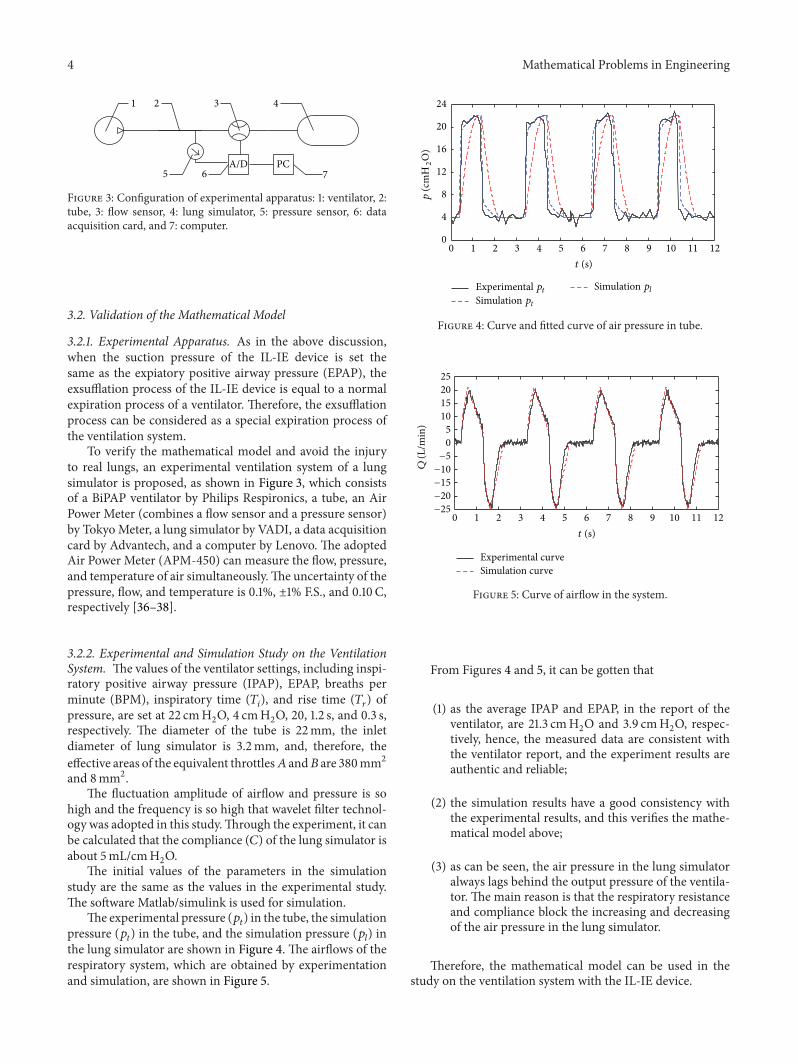
Figure 3: Configuration of experimental apparatus: 1: ventilator, 2:tube, 3: flow sensor, 4: lung simulator, 5: pressure sensor, 6: dataacquisition card, and 7: computer.
3.2. Validation of the Mathematical Model
3.2.1. Experimental Apparatus. As in the above discussion,when the suction pressure of the IL-IE device is set thesame as the expiatory positive airway pressure (EPAP), theexsufflation process of the IL-IE device is equal to a normalexpiration process of a ventilator. Therefore, the exsufflationprocess can be considered as a special expiration process ofthe ventilation system.
To verify the mathematical model and avoid the injuryto real lungs, an experimental ventilation system of a lungsimulator is proposed, as shown in Figure 3, which consistsof a BiPAP ventilator by Philips Respironics, a tube, an AirPower Meter (combines a flow sensor and a pressure sensor)by TokyoMeter, a lung simulator by VADI, a data acquisitioncard by Advantech, and a computer by Lenovo. The adoptedAir Power Meter (APM-450) can measure the flow, pressure,and temperature of air simultaneously.The uncertainty of thepressure, flow, and temperature is 0.1%, ±1% F.S., and 0.10 C,respectively [36–38].
3.2.2. Experimental and Simulation Study on the VentilationSystem. The values of the ventilator settings, including inspi-ratory positive airway pressure (IPAP), EPAP, breaths perminute (BPM), inspiratory time (𝑇
𝑖), and rise time (𝑇
𝑟) of
pressure, are set at 22 cmH2O, 4 cmH
2O, 20, 1.2 s, and 0.3 s,
respectively. The diameter of the tube is 22mm, the inletdiameter of lung simulator is 3.2mm, and, therefore, theeffective areas of the equivalent throttles𝐴 and𝐵 are 380mm2and 8mm2.
The fluctuation amplitude of airflow and pressure is sohigh and the frequency is so high that wavelet filter technol-ogy was adopted in this study.Through the experiment, it canbe calculated that the compliance (𝐶) of the lung simulator isabout 5mL/cmH
2O.
The initial values of the parameters in the simulationstudy are the same as the values in the experimental study.The software Matlab/simulink is used for simulation.
The experimental pressure (𝑝𝑡) in the tube, the simulation
pressure (𝑝𝑡) in the tube, and the simulation pressure (𝑝
𝑙) in
the lung simulator are shown in Figure 4. The airflows of therespiratory system, which are obtained by experimentationand simulation, are shown in Figure 5.
0 1 2 3 4 5 6 7 8 9 10 11 120
4
8
12
16
20
24
Experimental ptSimulation pt
Simulation pl
p (c
mH
2O
)
t (s)
Figure 4: Curve and fitted curve of air pressure in tube.
0 1 2 3 4 5 6 7 8 9 10 11 12−25
−20
−15
−10
−5
0
5
10
15
20
25
Q (L
/min
)
Experimental curveSimulation curve
t (s)
Figure 5: Curve of airflow in the system.
From Figures 4 and 5, it can be gotten that
(1) as the average IPAP and EPAP, in the report of theventilator, are 21.3 cmH
2O and 3.9 cmH
2O, respec-
tively, hence, the measured data are consistent withthe ventilator report, and the experiment results areauthentic and reliable;
(2) the simulation results have a good consistency withthe experimental results, and this verifies the mathe-matical model above;
(3) as can be seen, the air pressure in the lung simulatoralways lags behind the output pressure of the ventila-tor. The main reason is that the respiratory resistanceand compliance block the increasing and decreasingof the air pressure in the lung simulator.
Therefore, the mathematical model can be used in thestudy on the ventilation system with the IL-IE device.

Mathematical Problems in Engineering 5
0 0.5 1 1.5 2 2.5 3 3.5 4
−30
−20
−10
0
10
20
p cm
H2O
p�-scps-scp�-t
ps-tp�-lps-l
t (s)
Figure 6: Pressure dynamics of the ventilation system.
4. Study on the Dynamics of the VentilationSystem with the IL-IE Device
4.1. Dynamics of the Ventilation System. As the complianceof the ventilated lung is set at 50mL/cmH
2O, the inner
diameters of the tube and the endotracheal intubation are setat 10mmand 7mm.The IPAP, EPAP, and suction pressure areset at 4 cmH
2O, 22 cmH
2O, and −30 cmH
2O, respectively.
When exsufflation flow is less than 2.7 L/s, the exsufflationprocess is terminated.
The curves of six pressures (namely, the output pressure(𝑝V-𝑠𝑐) of the ventilator in the ventilation process, the outputpressure (𝑝
𝑠-𝑠𝑐) of the IL-IE device in the secretion clearanceprocess, the pressure (𝑝V-𝑡) in the tube in the ventilationprocess, the pressure (𝑝
𝑠-𝑡) in the tube in the secretionclearance process, the pressure (𝑝V-𝑙) in the ventilated lungin the ventilation process, and the pressure (𝑝
𝑠-𝑙) in theventilated lung in the secretion clearance process) are shownin Figure 6. The airflow (𝑄V-𝑙) of the ventilated lung in theventilation process and the airflow (𝑄
𝑠-𝑙) of the ventilated lungin the secretion clearance process are shown in Figure 7.
As illustrated in Figures 6 and 7, the dynamic character-istics of the system during secretion clearance process can beseen.
Due to the respiratory resistance and the compliance,with a growth or a descent in the pressure in the tube,the pressure in the ventilated lung ascends or declinesaccordingly.
The pressure in the ventilated lung declines faster in thesecretion clearance process than in the expiration process.At the end of the exsufflation process, the pressure in theventilated lung is a little lower than the EPAP, which mayharm the patient’s respiratory system.
After the exsufflation process, tomaintain the EPAPof theventilation system, the ventilator continues to transfer air to
0 0.5 1 1.5 2 2.5 3 3.5 4
−3
−2
−1
0
1
2
Q (L
/s)
Q�-l
Qs-l
t (s)
Figure 7: Flow dynamics of the ventilated lung.
the ventilated lung, and then the pressures in the tube and thelung start to increase to the EPAP.
4.2. Influence of the key Parameters on the Dynamics of theVentilation System. According to [27], to clear secretionseffectively, the peak exsufflation airflow should be largerthan 2.7 L/s. In order to improve the secretion clearanceefficiency of the device, influences of some key parameters(such as the settings of the ventilator, the suction pressure,and the respiratory parameters of the ventilation system) onthe dynamics of the ventilation system should be studied.
4.2.1. Influence of the Suction Pressure on the Dynamics. Theinfluences of the suction pressure on the dynamic char-acteristics of the ventilation system are shown in Figures 8,9, and 10.
As illustrated in Figures 8, 9, and 10, it can be seen thatthe peak exsufflation airflow is negatively proportional
to the suction pressure. When the suction pressure is lowerthan −35 cmH
2O, the minimum pressure in the ventilated
lung increases proportionally with a growth in the suctionpressure. However, when the suction pressure is higher than−35 cmH
2O, the minimum pressure in the ventilated lung
may be higher than the EPAP.Therefore, decreasing the suction pressure can improve
the peak exsufflation airflow. But if the suction pressure is settoo low, theminimumpressure in the lungmay get lower thanthe EPAP, and thatmay injure the patient’s respiratory system.
4.2.2. Influences of the Effective Area of the Respiratory Airwayon the Dynamics. The influences of the effective area (𝐴
𝑟)
of the respiratory airway on the dynamics are depicted inFigures 11, 12, and 13.
As shown in Figures 11, 12, and 13, with a rise in theeffective area 𝐴
𝑟, the peak exsufflation airflow of the venti-
lated lung may ascend. When the effective area 𝐴𝑟is bigger
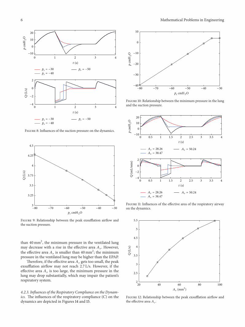
6 Mathematical Problems in Engineering
0 1 2 3 4
−10
0
10
20
p cm
H2O
ps = −30
ps = −40
ps = −50
0 1 2 3 4
ps = −30
ps = −40
ps = −50
−4
−2
0
2
Q (L
/s)
t (s)
t (s)
Figure 8: Influences of the suction pressure on the dynamics.
−80 −70 −60 −50 −40 −30
ps cmH2O
3
3.25
3.5
3.75
4
4.25
4.5
Q (L
/s)
Figure 9: Relationship between the peak exsufflation airflow andthe suction pressure.
than 40mm2, the minimum pressure in the ventilated lungmay decrease with a rise in the effective area 𝐴
𝑟. However,
the effective area 𝐴𝑟is smaller than 40mm2; the minimum
pressure in the ventilated lung may be higher than the EPAP.Therefore, if the effective area 𝐴
𝑟gets too small, the peak
exsufflation airflow may not reach 2.7 L/s. However, if theeffective area 𝐴
𝑟is too large, the minimum pressure in the
lung may drop substantially, which may impair the patient’srespiratory system.
4.2.3. Influences of the Respiratory Compliance on the Dynam-ics. The influences of the respiratory compliance (𝐶) on thedynamics are depicted in Figures 14 and 15.
−80 −70 −60 −50 −40 −30
ps cmH2O
−40
−30
−20
−10
0
10
p cm
H2O
Figure 10: Relationship between the minimum pressure in the lungand the suction pressure.
Ar = 28.26
0 0.5 1 1.5 2 2.5 3 3.5 4
Ar = 28.26
0 0.5 1 1.5 2 2.5 3 3.5 4
−10
0
10
20
p cm
H2O
−4
−2
0
2
Q (m
L/m
in)
t (s)
t (s)
Ar = 38.47Ar = 50.24
Ar = 38.47
Ar = 50.24
Figure 11: Influences of the effective area of the respiratory airwayon the dynamics.
20 40 60 80 1002
2.5
3
3.5
4
4.5
5
5.5
Q (L
/s)
Ar (mm2)
Figure 12: Relationship between the peak exsufflation airflow andthe effective area 𝐴
𝑟.

Mathematical Problems in Engineering 7
20 40 60 80 100−20
−15
−10
−5
0
5
p cm
H2O
Ar (mm2)
Figure 13: Relationship between the minimum pressure in the lungand the effective area 𝐴
𝑟.
0 1 2 3 4
C = 3
C = 5
C = 7
0 1 2 3 4
C = 3
C = 5
C = 7
5
10
15
20
p cm
H2O
−2
0
2
Q (L
/s)
t (s)
t (s)
Figure 14: Influences of the respiratory compliance on the dynam-ics.
It can be seen that the minimum pressure in thelung is hardly influenced by the respiratory compliance.However, when the respiratory compliance is bigger than5mL/cmH
2O, the peak exsufflation airflow descends with an
increase in the respiratory compliance. When the respiratorycompliance is smaller than 5mL/cmH
2O, the peak exsuffla-
tion airflow almost remains the same.Therefore, with the deposition of the secretion in the
respiratory airway, its effective area may be narrowed, andthen the peak exsufflation airflow may be reduced. With anincrease in the respiratory compliance, the peak exsufflationairflow may be reduced. To ensure the secretion clearanceefficiency, the suction pressure must be elevated properly.
0 5 10 15 20 252.7
2.8
2.9
3
3.1
3.2
Q (L
/s)
C (mL/cmH2O)
Figure 15: Relationship between the peak exsufflation airflow andthe respiratory compliance.
0 1 2 3 4
0 1 2 3 4
5
10
15
20
25p
cmH
2O
−2
0
2
Q (L
/s)
t (s)
t (s)
pIPAP = 16
pIPAP = 22
pIPAP = 28
pIPAP = 16
pIPAP = 22
pIPAP = 28
Figure 16: Influences of the IPAP on the dynamics.
4.2.4. Influences of the Ventilator Settings on the Dynamics.The influences of the IPAP and EPAP on the dynamics areshown in Figures 16 and 17.
From Figures 16 and 17, it can be seen thatincreasing the IPAP can improve the peak exsufflation
airflow and prolong the exsufflation duration. However, theexsufflation airflow dynamics are hardly influenced by theEPAP.
Therefore, increasing the IPAP is a method to improvethe secretion clearance efficiency, though the IPAP can beadjusted by the IL-IE automatically.

8 Mathematical Problems in Engineering
0
10
20
p cm
H2O
0 1 2 3 4
−2
0
2
Q (L
/s)
0 1 2 3 4
t (s)
t (s)
pEPAP = 2
pEPAP = 4
pEPAP = 6
pEPAP = 2
pEPAP = 4
pEPAP = 6
Figure 17: Influences of the EPAP on the dynamics.
5. Conclusions
In this research, to improve the secretion clearance efficiencyand lay a foundation for the optimization of the IL-IE device,the mathematical model of the secretion clearance system isset up. Through the research on the ventilation system, it canbe concluded that
(1) the experimental and the simulation results areauthentic and reliable, and the mathematical modelcan be used in the study on the ventilation systemwiththe IL-IE device;
(2) with a decrease in the suction pressure, the peakexsufflation airflow of the ventilated lung may riseproportionally, but the minimum pressure in theventilated lung may almost descend proportionally.To improve the efficiency of the secretion clearance,the suction pressure can be elevated properly;
(3) with the deposition of secretion or a growth inrespiratory compliance, the peak exsufflation airflowmay be reduced. To ensure the secretion clearanceefficiency, the suction pressure must be elevatedappropriately;
(4) increasing the IPAP is a method to improve thesecretion clearance efficiency, though the IPAP can beadjusted by the IL-IE.
Nomenclature
𝐴: Equivalent effective area [m2]𝑏: Critical pressure ratio = 0.5283𝐶: Respiratory compliance [L/cmH
2O]
𝑑: Diameter of equivalent effective area [m]
𝑙: Length, m𝑚: Mass of air [kg]𝑛: Coefficient of proportionality𝑝: Pressure [pa]𝑞: Air mass flow [kg/s]𝑄: Air volume flow [m3/s]𝑅: Gas constant = 287 [J/(kg⋅K)]𝑡: Time [s]𝑉: Volume [m3]𝜌: Density [kg/m3]𝜅: Specific heat ratio = 1.4𝜃: Temperature [K],
Subscripts
𝑎: The standard reference atmosphere state𝐴: Equivalent combination 𝐴
𝐵: Equivalent combination 𝐵
𝑐: Cycle𝑑: Downstream side𝑒: Expiration𝑓: Flow of airepap: Expiatory positive airway pressure𝑖: Inspirationil-ie: The IL-IE deviceipap: Inspiratory positive airway pressure𝑙: Lung𝑟: Pressure rising time𝑠: Suction process/exsufflation process𝑡: Tube𝑢: Upstream sideV: Ventilator or ventilation process.
Conflict of Interests
The authors declare that there is no conflict of interestsregarding the publication of this paper.
Acknowledgment
The research is funded by Open Foundation of the State KeyLaboratory of Fluid Power Transmission and Control.
References
[1] F. T. Tehrani, “A control system for mechanical ventilation ofpassive and active subjects,” Computer Methods and Programsin Biomedicine, vol. 110, no. 3, pp. 511–518, 2013.
[2] S. P. Pilbeam and J. M. Cairo, Mechanical Ventilation, Physio-logical and Clinical Application, Mosby Elsevier, St. Louis, Mo,USA, 4th edition, 2006.
[3] R. L. Chatburn, “Classification of ventilator modes: update andproposal for implementation,” Respiratory Care, vol. 52, no. 3,pp. 301–323, 2007.
[4] V. Gerber and N. E. Robinson, “Airway secretions and mucocil-iary function,” Equine RespiratoryMedicine and Surgery, pp. 55–69, 2007.

Mathematical Problems in Engineering 9
[5] L. Rose and G. Hanlon, “Ventilation and oxygenation manage-ment,” in ACCCN’s Critical Care Nursing, p. 381, 2011.
[6] F. Glynn and J. E. Fenton, “Diagnosis and management ofsupraglottitis (epiglottitis),” Current Infectious Disease Reports,vol. 10, no. 3, pp. 200–204, 2008.
[7] H. Katori andM. Tsukuda, “Acute epiglottitis: analysis of factorsassociated with airway intervention,” Journal of Laryngology &Otology, vol. 119, no. 12, pp. 967–972, 2005.
[8] L.-. Guldfred, D. Lyhne, and B. C. Becker, “Acute epiglotti-tis: epidemiology, clinical presentation, management and out-come,” Journal of Laryngology and Otology, vol. 122, no. 8, pp.818–823, 2008.
[9] C. Newmarch, “Caring for the mechanically ventilated patient:part two,” Nursing Standard, vol. 20, no. 18, pp. 55–66, 2006.
[10] P. Feltracco, G. Falasco, S. Barbieri, M. Milevoj, E. Serra, and C.Ori, “Anesthetic considerations for nontransplant procedures inlung transplant patients,” Journal of Clinical Anesthesia, vol. 23,no. 6, pp. 508–516, 2011.
[11] A. Sinha and F. Carli, “The role of regional anaesthesia inpatient outcome: thoracic and abdominal surgeries,” Techniquesin Regional Anesthesia and Pain Management, vol. 12, no. 4, pp.183–193, 2008.
[12] S. M. Maggiore, F. Lellouche, J. Pigeot et al., “Preventionof endotracheal suctioning-induced alveolar derecruitment inacute lung injury,” The American Journal of Respiratory andCritical Care Medicine, vol. 167, no. 9, pp. 1215–1224, 2003.
[13] T. Dyhr, J. Bonde, and A. Larsson, “Lung recruitment manoeu-vres are effective in regaining lung volume and oxygenationafter open endotracheal suctioning in acute respiratory distresssyndrome,” Critical Care, vol. 7, no. 1, pp. 55–62, 2003.
[14] U. Munnur, V. D. Bandi, and M. A. Gropper, “Airway manage-ment and mechanical ventilation in pregnancy,” in PulmonaryProblems in Pregnancy, K. Rosene-Montella and G. Bourjeily,Eds., Respiratory Medicine, pp. 385–403, 2009.
[15] M. Tsoumakidou and N. M. Siafakas, “Novel insights into theaetiology and pathophysiology of increased airway inflamma-tion during COPD exacerbations.,” Respiratory Research, vol. 7,article 80, 2006.
[16] B. M. Morrissey, “Pathogenesis of Bronchiectasis,” Clinics inChest Medicine, vol. 28, no. 2, pp. 289–296, 2007.
[17] D. Huh, H. Fujioka, Y. Tung et al., “Acoustically detectablecellular-level lung injury induced by fluid mechanical stressesin microfluidic airway systems,” Proceedings of the NationalAcademy of Sciences of the United States of America, vol. 104, no.48, pp. 18886–18891, 2007.
[18] J. Sancho, E. Servera, J. Dıaz, and J. Marın, “Efficacy of mech-anical insufflation-exsufflation in medically stable patients withamyotrophic lateral sclerosis,” Chest, vol. 125, no. 4, pp. 1400–1405, 2004.
[19] B. Fauroux, N. Guillemot, G. Aubertin et al., “Physiologicbenefits ofmechanical insufflation-exsufflation in children withneuromuscular diseases,”Chest, vol. 133, no. 1, pp. 161–168, 2008.
[20] N. Lechtzin, C. M. Wiener, L. Clawson, V. Chaudhry, and G. B.Diette, “Hospitalization in amyotrophic lateral sclerosis: causes,costs, and outcomes,”Neurology, vol. 56, no. 6, pp. 753–757, 2001.
[21] R. D. Branson, “Secretion management in the mechanicallyventilated patient,” Respiratory Care, vol. 52, no. 10, pp. 1328–1342, 2007.
[22] A. Lucchini, A. Zanella, G. Bellani et al., “Tracheal secretionmanagement in the mechanically ventilated patient: compari-son of standard assessment and an acoustic secretion detector,”Respiratory Care, vol. 56, no. 5, pp. 596–603, 2011.
[23] M. K. Sontag, A. L. Quittner, A. C. Modi et al., “Lessonslearned from a randomized trial of airway secretion clearancetechniques in cystic fibrosis,” Pediatric Pulmonology, vol. 45, no.3, pp. 291–300, 2010.
[24] J. S. Flores, F. A. Teixeira, P. M. E. Rovedder, B. Ziegler, and P. D.T. R. Dalcin, “Adherence to airway clearance therapies by adultcystic fibrosis patients,” Respiratory Care, vol. 58, no. 2, pp. 279–285, 2013.
[25] D. N. Homnick, “Mechanical insufflation-exsufflation for air-waymucus clearance,”Respiratory Care, vol. 52, no. 10, pp. 1296–1305, 2007.
[26] C. Guerin, G. Bourdin, V. Leray et al., “Performance of thecoughAssist insufflation-exsufflation device in the presence ofan endotracheal tube or tracheostomy tube: a bench study,”Respiratory Care, vol. 56, no. 8, pp. 1108–1114, 2011.
[27] J. D. Finder, “Airway clearance modalities in neuromusculardisease,” Paediatric Respiratory Reviews, vol. 11, no. 1, pp. 31–34,2010.
[28] V. Porot and C. Guerin, “Bench assessment of a newinsufflation-exsufflation device,” Respiratory Care, vol. 58, no. 9,pp. 1536–1540, 2013.
[29] B. Morrow, M. Zampoli, H. van Aswegen et al., “Mechanicalinsufflation-exsufflation for people with neuromuscular disor-ders,” Cochrane Database of Systematic Reviews, no. 12, ArticleID CD010044, 2013.
[30] J. R. Bach, “Pulmonary rehabilitation considerations forDuchenne Muscular Dystrophy: the prolongation of life byrespiratory muscle aids,” Critical Reviews in Physical and Reha-bilitation Medicine, vol. 3, pp. 239–269, 1992.
[31] E. Be’eri, “Automated airway secretion clearance in the ICU byin-line inexsufflation: clinical implications and technology,” inHumidification in the Intensive Care Unit, pp. 237–243, Springer,Berlin, Germany, 2012.
[32] R. L. Chatburn, “Computer control of mechanical ventilation,”Respiratory Care, vol. 49, no. 5, pp. 507–517, 2004.
[33] J. X. Brunner, History and Principles of Closed-Loop ControlApplied to Mechanical Ventilation, 2002.
[34] M. Borrello, “Modeling and control of systems for critical careventilation,” in Proceedings of the American Control Conference,pp. 2166–2180, Portland, Ore, USA, June 2005.
[35] N. Jaimchariyatam, R. A. Dweik, R. Kaw, and L. S. Aboussouan,“Polysomnographic determinants of nocturnal hypercapnia inpatients with sleep apnea,” Journal of Clinical Sleep Medicine,vol. 9, no. 3, pp. 209–215, 2013.
[36] Y. Shi and M. Cai, “Working characteristics of two kinds of air-driven boosters,” Energy Conversion and Management, vol. 52,no. 12, pp. 3399–3407, 2011.
[37] M.Cai, T. Funaki, K. Kawashima, andT.Kagawa, “Developmentof pneumatic power meter for energy saving,” in Proceedings ofthe Symposium on Fluid Power System at Spring, Tokyo, Japan,2003.
[38] M. Cai, K. Kawashima, and T. Kagawa, “Power assessment offlowing compressed air,” Journal of Fluids Engineering, Transac-tions of the ASME, vol. 128, no. 2, pp. 402–405, 2006.

Submit your manuscripts athttp://www.hindawi.com
Hindawi Publishing Corporationhttp://www.hindawi.com Volume 2014
MathematicsJournal of
Hindawi Publishing Corporationhttp://www.hindawi.com Volume 2014
Mathematical Problems in Engineering
Hindawi Publishing Corporationhttp://www.hindawi.com
Differential EquationsInternational Journal of
Volume 2014
Applied MathematicsJournal of
Hindawi Publishing Corporationhttp://www.hindawi.com Volume 2014
Probability and StatisticsHindawi Publishing Corporationhttp://www.hindawi.com Volume 2014
Journal of
Hindawi Publishing Corporationhttp://www.hindawi.com Volume 2014
Mathematical PhysicsAdvances in
Complex AnalysisJournal of
Hindawi Publishing Corporationhttp://www.hindawi.com Volume 2014
OptimizationJournal of
Hindawi Publishing Corporationhttp://www.hindawi.com Volume 2014
CombinatoricsHindawi Publishing Corporationhttp://www.hindawi.com Volume 2014
International Journal of
Hindawi Publishing Corporationhttp://www.hindawi.com Volume 2014
Operations ResearchAdvances in
Journal of
Hindawi Publishing Corporationhttp://www.hindawi.com Volume 2014
Function Spaces
Abstract and Applied AnalysisHindawi Publishing Corporationhttp://www.hindawi.com Volume 2014
International Journal of Mathematics and Mathematical Sciences
Hindawi Publishing Corporationhttp://www.hindawi.com Volume 2014
The Scientific World JournalHindawi Publishing Corporation http://www.hindawi.com Volume 2014
Hindawi Publishing Corporationhttp://www.hindawi.com Volume 2014
Algebra
Discrete Dynamics in Nature and Society
Hindawi Publishing Corporationhttp://www.hindawi.com Volume 2014
Hindawi Publishing Corporationhttp://www.hindawi.com Volume 2014
Decision SciencesAdvances in
Discrete MathematicsJournal of
Hindawi Publishing Corporationhttp://www.hindawi.com
Volume 2014 Hindawi Publishing Corporationhttp://www.hindawi.com Volume 2014
Stochastic AnalysisInternational Journal of