Center for Tokamak Transient Simulations FY2019 Progress ...
Upload
nguyenliemCategory
view
231download
0
Research ArticleTransient Simulations in Hydropower Stations Based ona Novel Turbine Boundary
Yanna Liu Jiandong Yang Jiebin Yang Chao Wang and Wei Zeng
State Key Laboratory of Water Resources and Hydropower Engineering Science Wuhan University Wuhan 430072 China
Correspondence should be addressed to Jiebin Yang jbyang830212whueducn
Received 11 March 2016 Accepted 31 May 2016
Academic Editor Jian Guo Zhou
Copyright copy 2016 Yanna Liu et al This is an open access article distributed under the Creative Commons Attribution Licensewhich permits unrestricted use distribution and reproduction in any medium provided the original work is properly cited
Most accidents in hydropower stations happened during transient processes thus simulation of these processes is important forstation design and safety operation This study establishes a mathematical model of the transient process in hydropower stationsand presents a new method to calculate the hydraulic turbine boundary based on an error function of the rotational speed Themathematical derivation shows that the error function along the equal-opening characteristic curve is monotonic and has oppositesigns at the two sides which means that a unique solution exists to make the error function null Thus iteration of the transientsimulation is unique and monotonous which avoids iterative convergence or false solution and improves the solution efficiencycompared with traditional methods Simulation of an engineering case illustrates that the results obtained by the error function arereasonable Then the accuracy and feasibility of the mathematical model using the proposed solution are verified by comparisonwith model and field tests
1 Introduction
Because hydropower stations play an important role inthe peak regulation and valley filling of a power grid thehydraulic turbine needs to frequently change its operatingconditions and experiences many transient processes Thetransient process in hydropower stations including theinteractions among hydraulics mechanism and electricity iscomplicated The closure of guide vanes and spherical valveinduces a change in the flow inertia which causes changesin the turbine rotational speed and hydraulic pressure inthe piping systemWhen the working condition dramaticallychanges during transients drastic changes in the water-hammer pressure and high rotational speed may lead toserious accidents thatwill endanger the safety of the hydraulicstructure and turbine unit [1ndash3] and affect the power gridstability [4] Therefore simulating the transient process ofhydropower stations is necessary The calculation accuracy isdirectly related to the design of the water diversion systemsafe operation of the hydropower plant and power quality
The calculation methods of the water-hammer pressureare analytical [5 6] graphical [7 8] and computer-numerical[9] The analytical method is based on the chain equation of
Allievi and the simplifications of the hydraulic turbine as avalveThis method is suitable for simple tube Pelton turbinesOn the basis of the analytical method the graphical methodcombines the water-hammer wave reflection and superposi-tion with the turbine characteristic curves and guide-vaneclosing scheme The traditional numerical simulation canbe classified into two types time- and frequency-domainmethods The time-domain method includes the method ofcharacteristics (MOC) [8ndash13] finite difference (FD) [14 15]and finite volume (FV) [16 17] In these methods the waterdelivery system is divided into a limited number of calculatedcells MOC is mostly applied owing to its advantages highefficiency of computation easy implementation for boundaryconditions easy parallelization with FD and FV for pipelineprocessing [18 19] and so on By using MOC varioustransition processes can be simulated In the frequency-domain method [9] the basic equations are linearized toobtain the transfer function of the pipeline Combined withthe transfer functions of the governor and turbine obtainingthe dynamic responses of the hydropower system becomeseasy Irrespective of the time or frequency domain thetransient simulation model includes the pipe model and theturbine boundary
Hindawi Publishing CorporationMathematical Problems in EngineeringVolume 2016 Article ID 1504659 13 pageshttpdxdoiorg10115520161504659
2 Mathematical Problems in Engineering
The turbine boundary in the transient simulations can bedivided into two categories [20] One is based on the geomet-ric size of the turbine [21ndash23] The other is the characteristiccurve based on the model tests which is generally adoptedin the transient simulations The characteristic curves areusually transformed into curves with the unit speed as anindependent variable and the unit discharge and unit torqueas dependent variables To enable transient simulation theturbine characteristic curves are formulated into piecewisepolygonal functions using an auxiliary grid [24ndash26] Thenthe operating point consisting of unit parameters is expressedas
1198761015840
1= 1198911(1198991015840
1 119910) = 119860
1+ 11986021198991015840
1(1)
1198721015840
1= 1198912(1198991015840
1 119910) = 119861
1+ 11986121198991015840
1 (2)
By combining the two equations and other boundary equa-tions a one-element cubic equation of the square root ofthe head can be obtained and the equation can be solvedusing the NewtonndashSimpson iterative method [27] The rootsobtained by this method are correlated to the initial valuesand it can only obtain the root near the initial valuesMeanwhile the first-order derivative of the function whichis taken as the denominator should be neither too small nornull otherwise the iteration cannot be carried out Generallywe take the root of last instant as the initial value If the unitparameters obtained from the root of the iteration just lie inthe line segment assumed previously the root is consideredas the correct solution and it will be taken as the initialvalues of the iteration in next instant If the unit parametersare not in the assumed line segment we should extendthe search range and solve the cubic equation again untilwe get the right line segment or search all over the equal-opening curve If all of the line segments of the equal-openingcurve cannot get a right root we will reduce the accuracyof the iteration properly and search again If all the methodsproposed above cannot get a root then we will select the rootwhose operating point is the closest to that of last instant asthe right solution Obviously this calculation method suffersfrom two shortcomings First the root search direction isambiguous when the desired operating point is beyond theline segment it is not clear whether the next search shouldtarget the last or next segment of the current line segmentSecond the roots obtained by the NewtonndashSimpson iterativemethod are correlated to the initial values if the initial valuesare incorrect the iteration resultsmay be beyond the assumedline segment Therefore the equation may either becomeunsolvable or be incorrectly solved
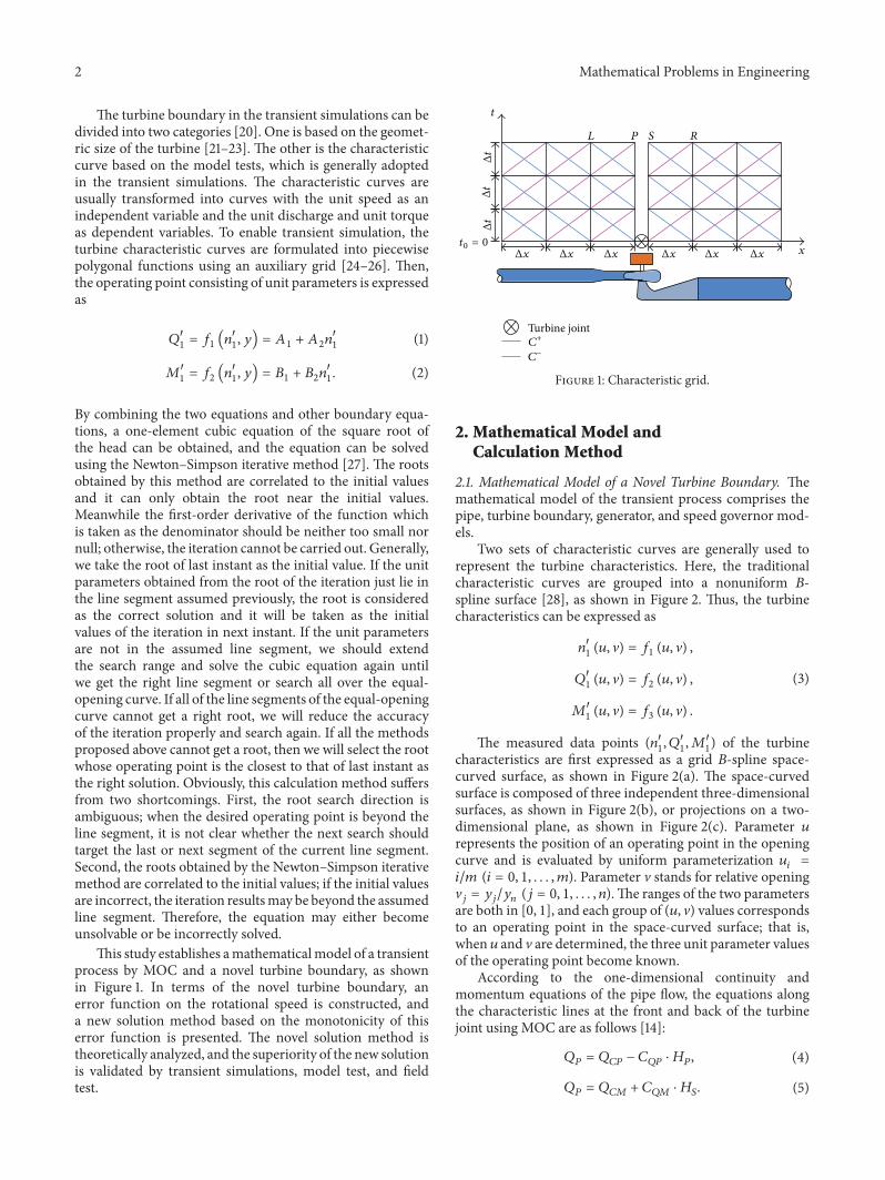
This study establishes amathematicalmodel of a transientprocess by MOC and a novel turbine boundary as shownin Figure 1 In terms of the novel turbine boundary anerror function on the rotational speed is constructed anda new solution method based on the monotonicity of thiserror function is presented The novel solution method istheoretically analyzed and the superiority of the new solutionis validated by transient simulations model test and fieldtest
t
Δt
Δt
Δt
t0 = 0Δx Δx Δx Δx Δx Δx x
L P S R
C+
Cminus
Turbine joint
Figure 1 Characteristic grid
2 Mathematical Model andCalculation Method
21 Mathematical Model of a Novel Turbine Boundary Themathematical model of the transient process comprises thepipe turbine boundary generator and speed governor mod-els
Two sets of characteristic curves are generally used torepresent the turbine characteristics Here the traditionalcharacteristic curves are grouped into a nonuniform 119861-spline surface [28] as shown in Figure 2 Thus the turbinecharacteristics can be expressed as
1198991015840
1(119906 V) = 119891
1(119906 V)
1198761015840
1(119906 V) = 119891
2(119906 V)
1198721015840
1(119906 V) = 119891
3(119906 V)
(3)
The measured data points (11989910158401 1198761015840
11198721015840
1) of the turbine
characteristics are first expressed as a grid 119861-spline space-curved surface as shown in Figure 2(a) The space-curvedsurface is composed of three independent three-dimensionalsurfaces as shown in Figure 2(b) or projections on a two-dimensional plane as shown in Figure 2(c) Parameter 119906represents the position of an operating point in the openingcurve and is evaluated by uniform parameterization 119906
119894=
119894119898 (119894 = 0 1 119898) Parameter V stands for relative openingV119895= 119910119895119910119899(119895 = 0 1 119899)The ranges of the two parameters
are both in [0 1] and each group of (119906 V) values correspondsto an operating point in the space-curved surface that iswhen 119906 and V are determined the three unit parameter valuesof the operating point become known
According to the one-dimensional continuity andmomentum equations of the pipe flow the equations alongthe characteristic lines at the front and back of the turbinejoint using MOC are as follows [14]
119876119875= 119876119862119875minus 119862119876119875sdot 119867119875 (4)
119876119875= 119876119862119872+ 119862119876119872sdot 119867119878 (5)
Mathematical Problems in Engineering 3
Q9984001
M9984001
PiPi+1
n9984001
(a) Space-curved surface of the characteristic curves
n9984001
u0 u1 ui ui+1 umn
j+1
j10 u
P998400i P998400
i+1
P998400998400i P998400998400
i+1
(b) Space-curved surface of 11989910158401(119906 V) = 119891
1(119906 V)
u0 u1 ui ui+1 um
n
j+1
j
1
0u
P998400998400i
P998400998400i+1
(c) Parameterization plane
Figure 2 Nonuniform 119861-spline surface of the turbine characteristics
119876119862119875 119862119876119875 119876119862119872
and 119862119876119872
in (4) and (5) are all values of theprevious instant and are known values in the current instant119876119862119875
and 119876119862119872
are determined by the flow and head of theprevious instant respectively and 119862
119876119875and 119862
119876119872are both
correlated to thewave velocity and pipe area respectively andare positive constants
The equations for the unit parameters are expressed as
119876119875= 1198761015840
11198632
1radic119867119875minus 119867119878 (6)
119899 =1198991015840
1radic119867119875minus 119867119878
1198631
(7)
119872119905= 1198721015840
11198633
1(119867119875minus 119867119878) (8)
The first derivative of the differential equation of thegenerator is expressed as
119869119889120596
119889119905= 119872119905minus119872119892minus30119890119892119875119903
1198992119903120587Δ119899 (9)
Under an off-grid operation119872119892= 0 and 119890
119892= 0 Thus
the generator equation can be simplified as
119899 = 1198990+01875 (119872
119905+1198721199050) Δ119905
1198661198632 (10)
The guide-vane opening is defined in advance thus
119910 = 119891 (119905) (11)
Parameter V represents the relative opening therefore
V =119910
119910max (12)
If the turbine is operating under a frequency or powercontrol (11) is eliminated whereas the speed governor equa-tion is added
The unknowns in these equations include the heads119867119875and 119867
119878of the inlet and outlet of the rotating wheel
respectively discharge 119876119875 rotating speed 119899 torque119872
119905 unit
speed 11989910158401 unit discharge 1198761015840
1 unit torque 1198721015840
1 guide-vane
opening 119910 and parameters 119906 and V In general elevenequations with eleven unknowns exist
22 Calculation Steps of the Transient Process During thecalculation of the load rejection in the transient process theclosure law of the guide vane is given and the guide-vaneopening is known at every instant Thus solving the above-mentioned boundary conditions is simplified to seeking theoperating points that satisfy the equations With a knownopening value the equations can be solved as follows [27]
4 Mathematical Problems in Engineering
(1) We assume a value for parameter 119906 and obtain thethree unit parameters from (3) Inserting 119883 = radic119867119901 minus 1198671198781198621= 119876119862119875119862119876119875+ 119876119862119872119862119876119872
1198622= 1119862
119876119875+ 1119862
119876119872 and
119864 = 01875Δ1199051198661198632 into (4)ndash(6) and simplifying the result
yield
1198832+ 1198622sdot 1198761015840
1sdot 1198632
1119883 minus 119862
1= 0 (13)
Then the two roots are obtained as follows
1198831=minus11986221198761015840
11198632
1+ radic(119862
21198632111987610158401)2
+ 41198621
2
(14a)
1198832=minus11986221198761015840
11198632
1minus radic(119862
21198632111987610158401)2
+ 41198621
2
(14b)
119883 represents the square root of the head and is always apositive real number According to (14a) and (14b) 119883
1gt 0
when 1198621gt 0 When 119862
1lt 0 and 1198761015840
1le minusradicminus4119862
11198622211986341 both
1198831and 119883
2are positive real numbers and we need to select
the right one Under other conditions when both1198831and119883
2
are nonpositive real numbers Step (1) is repeated(2)We insert119883 into (7) and (8) and obtain rotating speed
119899 and torque119872119905 We insert119872
119905into (10) and obtain rotating
speed 119899lowast(3) We define Ω = 119899 minus 119899
lowast When Ω = 0 parameter 119906 isreasonably assumed 119883 and the three unit parameter valuesof the operating point are desired Hence we proceed to Step(4) otherwise Steps (1)ndash(3) are repeated
(4) We insert 119883 into (4)ndash(6) to obtain the values of 119867119875
119867119878 and 119876
119875
The flowchart is shown in Figure 3 When 1198621gt 0 the
search interval of Ω = 0 is the whole equal-opening curve(ie from 119906 = 0 to 119906 = 1) when 119862
1lt 0 the search interval
is the part in which 11987610158401le minusradicminus4119862
11198622211986341is in the pump and
reverse-pump regions In general this study needs to solvetwo problems (1) searching for the operating point whereΩ = 0 in a known equal-opening curve and (2) distinguishingbetween119883
1and119883
2when 119862
1lt 0 and 1198761015840
1le minusradicminus4119862
11198622211986341
Assumption 1 Ω is a monotonic function in the searchsegment of the equal-opening curve with parameter 119906
Assumption 2 Ω has opposite signs at the two boundarypoints of this segment
From Assumptions 1 and 2 a unique point must existwhere Ω = 0 The search direction of the root can bedetermined according to the monotonicity and the firstproblem in this study can be solved For the second problemthat is choosing between 119883
1or 1198832 if Ω is a monotonic
function by inserting 1198831or 1198832into Ω the value that can
make the signs of Ω at the search boundaries oppositeis required and the other value should be discarded Insummary to solve problems (1) and (2) we need to validateAssumptions 1 and 2
Yes
Yes
Yes
No
No
No
ni
Mti
HpHs Qp
i=
i+1
X =
Q9984001 le minusradic minus4C1
C22D
41
Assume u = uilowast
C1 ⩾ 0
X = X1i
X = X1i
nilowast
Ω = ni minus nilowast lt 120576
i=
i+1iminus1
Equations (4)ndash(6)
Equation (8)
Equation (7)Equation (10)
Equations (4) and (5)
Figure 3 Flowchart of the solution process of the turbine boundaryequations based on the space surface
3 Search Direction of 119883
31 Directional Derivative of Ω According to the directionalderivative theorem the directional derivative of Ω in linesegment 119875
119894119875119894+1
shown in Figure 2 can be expressed as [29]
120597Ω
120597119906=120597Ω
12059711989910158401
cos120572 + 120597Ω12059711987610158401
cos120573 + 120597Ω
12059711987210158401
cos 120574 (15)
We define Δ119871 = radic(Δ11989910158401)2 + (Δ1198761015840
1)2 + (Δ1198721015840
1)2 as the
length of the segment cos120572 = Δ11989910158401Δ119871 cos120573 = Δ1198761015840
1Δ119871 and
cos 120574 = Δ1198721015840
1Δ119871 as the cosines of the angles separately
formed by segment 119875119894119875119894+1
and the three coordinate axes inspace Then
120597Ω
120597119906=1
Δ119871(120597Ω
12059711989910158401
Δ1198991015840
1+120597Ω
12059711987610158401
Δ1198761015840
1+120597Ω
12059711987210158401
Δ1198721015840
1) (16)
Therefore the sign of 120597Ω120597119906 depends on the sign of thesum of Δ1198991015840
1120597Ω120597119899
1015840
1 Δ11987610158401120597Ω120597119876
1015840
1 and Δ1198721015840
1120597Ω120597119872
1015840
1 When
120597Ω120597119906 gt 0 Ω is a monotonically increasing function within119875119894119875119894+1
when 120597Ω120597119906 lt 0 Ω is monotonically decreasingFrom the calculation method presented in Section 22 and(7)ndash(10) Ω can be expressed as
Ω =1198831198991015840
1
1198631⏟⏟⏟⏟⏟⏟⏟119899
minus (1198641198721015840
11198633
11198832+ 1198990+ 119864119872
1199050)⏟⏟⏟⏟⏟⏟⏟⏟⏟⏟⏟⏟⏟⏟⏟⏟⏟⏟⏟⏟⏟⏟⏟⏟⏟⏟⏟⏟⏟⏟⏟⏟⏟⏟⏟⏟⏟⏟⏟⏟⏟⏟⏟⏟⏟⏟⏟⏟⏟
119899lowast
(17)
Mathematical Problems in Engineering 5
Table 1 Signs of the different terms at different segments
Segment 120597Ω
12059711989910158401
Δ1198991015840
1
120597Ω
12059711989910158401
Δ1198991015840
1
120597Ω
12059711987610158401
Δ1198761015840
1
120597Ω
12059711987610158401
Δ1198761015840
1
120597Ω
12059711987210158401
Δ1198721015840
1
120597Ω
12059711987210158401
Δ1198721015840
1
Pump region AB + + + + + + + minus minus
BC + + + + + + + minus minus
Pump braking region CD + + + + + + + + +
Turbine region
DE + + + + + + + + +EF + + + minus + minus + + +FG + + + minus + minus + minus minus
GH + + + minus minus + + minus minus
HI + minus minus minus minus + + minus minus
Braking region IJ + minus minus minus minus + + minus minus
Reverse-pump region JK + minus minus minus minus + + minus minus
KL + + + minus minus + + minus minus
The following parts will consider 119883 = 1198831as an example
for analysis 119883 = 1198832can be analyzed by the same method
The partial derivatives of (17) are as follows
120597Ω
12059711989910158401
=119883
1198631
120597Ω
12059711987610158401
=minus211986221198632
1119883
radic(11986221198632111987610158401)2
+ 41198621
(1198991015840
1
21198631
minus 1198641198633
11198721015840
1119883)
120597Ω
12059711987210158401
= 1198641198633
11198832
(18)
Evidently 120597Ω12059711989910158401and 120597Ω1205971198721015840
1are constants that are
greater than zero and the sign of 120597Ω12059711987610158401varies under the
following scenarios (1)When the operating point is locatedin the pump region or pump braking regionwhere 1198991015840
1lt 0
and 11987210158401gt 0 120597Ω1205971198761015840
1is positive (2) When the operating
point is located in the turbine braking region or reverse-pumpregion where 1198991015840
1gt 0 and 1198721015840
1lt 0 120597Ω1205971198761015840
1is negative (3)
When the operating point is located in the turbine region and1198991015840
1lt 2119864119863
4
11198721015840
1119883 (the estimatedmagnitude of 1198991015840
1is not greater
than 100) 120597Ω12059711987610158401is positive otherwise 120597Ω1205971198761015840
1is negative
The signs of Δ11989910158401 Δ11987610158401 and Δ1198721015840
1depend on the shape
of the equal-opening curve Because the characteristic curveof pump-turbine is the most complex this study considersthis curve as an example In particular the equal-openingcurve of pump-turbine has the following characteristics [30](as shown in Figure 4) Point A is the start point of thepump region Point B is the inflection point of the pumpoperating region PointC is the pointwhere the unit dischargeof the pump region is zero Point D is the point where theunit rotating speed is zero Point E is the point where 1198991015840
1=
21198641198634
11198721015840
1119883 in the turbine region Point F is the point where
the unit torque is the largest in the operating region of theturbine Point G is the point where the unit discharge is thelargest in the operating region of the turbine Point H isthe point where the unit rotating speed is the highest in theoperating region of the turbine Point I is the runaway pointPoint J is the point where the unit discharge is zero in the
0
0
AB
C
D E F G
HI
JK
L
M9984001
n9984001
n9984001
Q9984001
A998400
B998400
C998400
D998400 E998400 F998400G998400
H998400
I998400J998400
K998400
L998400
Figure 4 Key points of the characteristic curves
turbine region Point K is the point where the unit rotatingspeed is the lowest in the braking region of the turbine PointL is the end point of the reverse-pump region
Table 1 lists the changes in the signs of Δ11989910158401120597Ω120597119899
1015840
1
Δ1198761015840
1120597Ω120597119876
1015840
1 and Δ1198721015840
1120597Ω120597119872
1015840
1along the equal-opening
curve
32 Determination of the Monotonicity of Ω
321 Comparison between |Δ11989910158401120597Ω120597119899
1015840
1| and |Δ1198721015840
1120597Ω120597119872
1015840
1|
Assuming 1198701
as the ratio between |Δ1198991015840
1120597Ω120597119899
1015840
1| and
|Δ1198721015840
1120597Ω120597119872
1015840
1| we let
1198651=
100381610038161003816100381610038161003816100381610038161003816
Δ1198991015840
1
Δ11987210158401
100381610038161003816100381610038161003816100381610038161003816
1198652= 1198641198634
1119883
(19)
6 Mathematical Problems in Engineering
10
8
6
4
2
0
Func
tion
valu
e
20 40 60 80 100 120 1400
Point number
F1(n9984001 Q
9984001)
ABBCCDDEEF
FGGHHIIJJKKL
Figure 5 Variation in 1198651(1198991015840
1 1198761015840
1)
According to (18)
1198701=1198651
1198652
(20)
The magnitude of 11986411986341is usually approximately 10minus4 and the
magnitude of 119883 is usually in the range of 101ndash102 Hencethe magnitude of 1198641198634
1119883 is below 10minus2 Therefore along the
entire equal-opening curve the slopes approach infinity onlyin the BC segment of the pump region and at points Hand K in the turbine region as shown in Figure 5 wheremaybe 119865
1lt 1198652 |Δ11989910158401120597Ω120597119899
1015840
1| lt |Δ119872
1015840
1120597Ω120597119872
1015840
1| however
these areas are also the segments where |Δ11987610158401120597Ω120597119876
1015840
1| gt
|Δ1198721015840
1120597Ω120597119872
1015840
1| According to the signs of these three terms
in Table 1 we know that 120597Ω120597119906 gt 0 For the other intervalsof the equal-opening characteristic curve |Δ1198991015840
1120597Ω120597119899
1015840
1| ≫
|Δ1198721015840
1120597Ω120597119872
1015840
1|
Consequently except for the BC segment and the neigh-borhoods of points H and K the sign of 120597Ω120597119906 dependsmainly on the signs of Δ1198991015840
1120597Ω120597119899
1015840
1and Δ1198761015840
1120597Ω120597119876
1015840
1 whereas
Δ1198721015840
1120597Ω120597119872
1015840
1can be ignored
322 Comparison between |Δ11989910158401120597Ω120597119899
1015840
1| and |Δ1198761015840
1120597Ω120597119876
1015840
1|
Assuming 1198702
as the ratio between |Δ1198991015840
1120597Ω120597119899
1015840
1| and
|Δ1198761015840
1120597Ω120597119876
1015840
1| we let
1198653=
100381610038161003816100381610038161003816100381610038161003816
Δ1198991015840
1
Δ11987610158401
100381610038161003816100381610038161003816100381610038161003816
1198654=
100381610038161003816100381610038161198991015840
1minus 2119864119863
4
11198831198721015840
1
10038161003816100381610038161003816
radic119876101584021+ 411986211198622211986341
(21)
According to (18)
1198702=1198653
1198654
(22)
When 1198653gt 1198654 |Δ11989910158401120597Ω120597119899
1015840
1| gt |Δ119876
1015840
1120597Ω120597119876
1015840
1|
20 40 60 80 100 120 1400
Point number
0
200
400
600
800
1000
Func
tion
valu
e
F3(n9984001 Q
9984001)
ABBCCDDEEFFG
F4(n9984001 Q
9984001)
GHHIIJJKKL
Figure 6 Variation in 1198653(1198991015840
1 1198761015840
1) and 119865
4(1198991015840
1 1198761015840
1)
Figure 6 shows how the signs of 1198653and 119865
4change along
the equal-opening curve 1198653is determined by the shapes of
the characteristic curve It reaches a low value in the BCsegment and at points H and K in the entire opening curvewhile reaching a peak at point D 119865
4reaches its maximum
value when 11987610158401= minusradicminus4119862
11198622211986341and reaches its minimum
value near the 11989910158401axis In the pump braking and turbine oper-
ating regions where 11987610158401smoothly changes (the range of CG
or CH including EG) |Δ11989910158401120597Ω120597119899
1015840
1| gt |Δ119876
1015840
1120597Ω120597119876
1015840
1| At the
ends of the pump and reverse-pump regions |Δ11989910158401120597Ω120597119899
1015840
1| gt
|Δ1198761015840
1120597Ω120597119876
1015840
1| is also possible however the two positions are
usually beyond the calculation range of the transient processAt the other positions |Δ1198991015840
1120597Ω120597119899
1015840
1| lt |Δ119876
1015840
1120597Ω120597119876
1015840
1| exists
When 119883 = 1198831 opposite signs for Δ1198991015840
1120597Ω120597119899
1015840
1and
Δ1198761015840
1120597Ω120597119876
1015840
1occur at two positions The first position is the
curve segment EG where Δ11989910158401120597Ω120597119899
1015840
1gt 0 Δ1198761015840
1120597Ω120597119876
1015840
1lt
0 and |Δ11989910158401120597Ω120597119899
1015840
1| gt |Δ119876
1015840
1120597Ω120597119876
1015840
1| Then 120597Ω120597119906 gt 0
The second position is the curve segment HK whereΔ1198991015840
1120597Ω120597119899
1015840
1lt 0 Δ1198761015840
1120597Ω120597119876
1015840
1gt 0 and |Δ1198991015840
1120597Ω120597119899
1015840
1| lt
|Δ1198761015840
1120597Ω120597119876
1015840
1| Then 120597Ω120597119906 gt 0 At other positions
Δ1198991015840
1120597Ω120597119899
1015840
1and Δ1198761015840
1120597Ω120597119876
1015840
1are both greater than zero
Therefore 120597Ω120597119906 gt 0 along the characteristic curve and Ωis a monotonically increasing function
When119883 = 1198832 this condition can be demonstrated in the
same manner as 119883 = 1198831 Ω is a monotonically decreasing
function in the pump region as well as in the reverse-pumpregion (where 1198761015840
1le minusradicminus4119862
11198622211986341)
In summary Ω is a monotonic function in the searchsegments thus Assumption 1 is verified
33 Signs of Ω in the Search Boundary
331 When 1198621gt 0 If the current operating point (1198991015840
1119906=119901
1198761015840
1119906=119901) is on the left side of the 1198991015840
1= 0 axis 1198991015840
1119906=0lt 1198991015840
1119906=119901lt 0
and 11987610158401119906=0
lt 1198761015840
1119906=119901can be obtained According to (7) and
(14a) Ω119906=0lt 0 if 119883
119906=0gt 119883119906=119901
and 119899119906=0lt 119899119906=119901
lt 0 For the
Mathematical Problems in Engineering 7
Table 2 Basic pump-turbine information of the engineering cases
Rated 119875(MW)
Rated 119899(rpm)
Rated119867(m)
Rated 119876(m3s)
Rotational inertia(kgsdotm2)
Calculated119867 (m)
Calculated119876 (m3s)
Calculated119875 (MW)
3061 4286 419 8364 6000000 45700 7318 3061
end point (11989910158401119906=1
1198761015840
1119906=1) in the reverse-pump region 119899
119906=1gt
0 and Ω119906=1
gt 0 if 11989910158401119906=1
gt 0 As a result when 1198621gt 0 Ω
is a monotonic function within the range of 119906 = [0 1] andΩ119906=0sdotΩ119906=1lt 0 Therefore only one point exists whereΩ = 0
along the entire characteristic curveThe same conclusion canalso be drawn when the operating point is on the right side ofthe 11989910158401= 0 axis
332 When 1198621lt 0 Similarly when 119883 = 119883
1 Ω119906=0
lt 0 andΩ119906=1gt 0 When119883 = 119883
2 Ω119906=0gt 0 andΩ
119906=1lt 0
If 0 lt 119886 lt 119887 lt 1 for the boundary point (11989910158401119906=119886
1198761015840
1119906=119886)
where 11987610158401119906=119886
= minusradicminus411986211198622211986341in the pump region we can
obtain the result 119883 = 1198831= 1198832= radicminus119862
1by inserting 1198761015840
1119906=119886
into (14a) and (14b) Then inserting 119883 into (17) yields thefollowing result
Ω =1198991015840
1radicminus1198621
1198631⏟⏟⏟⏟⏟⏟⏟⏟⏟⏟⏟⏟⏟⏟⏟1
+ 1198641198721015840
11198633
11198621⏟⏟⏟⏟⏟⏟⏟⏟⏟⏟⏟⏟⏟⏟⏟⏟⏟⏟⏟
2
minus1198990⏟⏟⏟⏟⏟⏟⏟3
minus1198641198721199050⏟⏟⏟⏟⏟⏟⏟⏟⏟⏟⏟4
(23)
At the position where |11989910158401| is relatively larger the second and
fourth terms in (23) are smaller than the other two termsthus they can be ignored By comparing the first term withthe third term Ω
119906=119886lt 0 when 119862
1lt minus1198992
01198632
111989910158402
1 otherwise
Ω119906=119886
gt 0 Similarly at the boundary point (11989910158401119906=119887
1198761015840
1119906=119887)
where 11987610158401119906=119887
= minusradicminus411986211198622211986341in the reverse-pump region
Ω119906=119887gt 0 when 119862
1lt minus1198992
01198632
111989910158402
1 otherwiseΩ
119906=119887lt 0
In summary when 1198621lt minus1198992
01198632
111989910158402
1 Ω119906=0sdot Ω119906=119886
lt 0 (orΩ119906=119887sdot Ω119906=1lt 0) in the search boundary of the pump region
(or reverse-pump region) only if 119883 = 1198832 When 0 gt 119862
1gt
minus1198992
01198632
111989910158402
1Ω119906=0sdot Ω119906=119886lt 0 (orΩ
119906=119887sdot Ω119906=1lt 0) in the search
boundary of the pump region (or reverse-pump region) onlyif119883 = 119883
1
Based on the systematic discussions of1198621gt 0 and119862
1lt 0
two conclusions can be drawn (1) The signs of Ω at twoboundary points in the search segment are opposite thusAssumption 2 is verified (2)When119862
1lt minus1198992
01198632
111989910158402
1119883 = 119883
2
meanwhile when1198621gt minus1198992
01198632
111989910158402
1119883 = 119883
1Thus the second
problem is solved
4 Engineering Cases
41 Case One (Theoretical Validation) To validate the pro-posed solution simulations of the load rejection set in apumped-storage power station were carried out and pre-sented in this section The details of the pumped-storagepower station along with simulation results of both thetraditional method and proposed solution are presented asfollows
(1) Upstream reservoir(2) Main diversion tunnel(3) Upstream surge chamber(4) Diversion penstock(5) Spiral case(6) Pump-turbine and generator
(1)(2)
(3)
(4)
(5)(6)
(7)(8)
(9)
(10)(11)
(7) Draft tube(8) Tailrace penstock(9) Downstream surge chamber(10) Main tailrace tunnel(11) Downstream reservoir
1234
Figure 7 Schematic diagram of the piping system of a hydropowerstation
The simulated pumped-storage power station has fourunits (300MW each and 1200MW in total) supplied by asingle tunnel and two surge chambers were installed on bothupstream and downstream Figure 7 shows the schematiclayout of the station Table 2 lists the basic information of thesingle machines and the parameters of the calculated case
During the simulation all turbines simultaneouslyrejected their loads except for one that experienced aguide-vane mechanical failure and its opening remainedunchanged For the other three turbines with nomalfunctiontheir guide vanes held their position for 10 s and thencompletely shut in 15 s Figures 8(a)ndash8(d) show the differencebetween the transient parameters using the new solutionproposed in this paper and the traditional solution
Until 20 s the operating trajectories and variations in theflow and pressure at the inlet and outlet of the rotating wheelobtained by traditional method are more logical and crediblewith no obvious fluctuation After 20 s the operationaltrajectories become thicker at the reverse-S-shaped region ofthe turbine characteristic curve and even deviate from thescheduled equal-opening curve Obvious vibrations occur inboth the flow and pressure values indicating that the tradi-tional method is unable to determine the correct operatingpoints In contrast no obvious vibration is observed in thecalculation results obtained by the proposed method in thispaper and the calculation results until 20 s coincide withthose obtained by the traditional solutionTherefore this newmethod is clearly superior to the traditional solution and canimprove the calculation accuracy of the transient process
The traditional methods is to solve the head first andthen seek the operating point There may be more thanone solutions to the one-element cubic equation and theroots obtained by the NewtonndashSimpson iterative method arecorrelated to the initial values Because lack of sufficient
8 Mathematical Problems in Engineering
Traditional solutionNew solution
minus01
00
01
02
03
Q998400 1
(m3s
)
85 90 95 100 105 110 115 15080
n9984001 (rpm)
(a) Variation in trajectories
Traditional solutionNew solution
minus30
0
30
60
90
Q(m
3s
)
20 40 60 80 1000
Time (s)
(b) Variation in flows
Traditional solutionNew solution
200
300
400
500
600
700
800
H(m
)
20 40 60 80 1000
Time (s)
(c) Variation in pressure in spiral case
Traditional solutionNew solution
20 40 60 80 1000
Time (s)
minus100
minus50
0
50
100
150
200
H(m
)
(d) Variation in pressure in draft tube
Figure 8 Comparison of the results of the traditional and new solutions
accordance we take the root of last instant as the initial valueBut when the right root is the further one we will not obtainthe right root based on the current initial value Reducingthe iterative accuracy or specifying one root according to lastinstant may result in bigger errors and the unit parametersmay deviate from the equal-opening curve and the transientparameters will jump up and down nonphysically
The new method determines the unit parameters and thehead at the same time In the solving process the equationsof transient process and the operating point of the equal-opening curve are mutually restrained All roots obtained areconsistent with the physical conditions in the calculation ofthe transition process the operating points are in the equal-opening curve the rotational speeds calculated from speedequation and head equation are equal to each otherThereforethe present new solution method avoids the appearance ofwrong rootsThe results obtained are in line with the physicalphenomenon without obvious vibrations
42 Case Two (Model Validation) A pumped-storage stationmodel consisting of model units piping systems measuringsystem and generator system was established in the labora-tory The schematic of the model is shown in Figure 9 Twodifferent model pump-turbines manufactured by HarbinElectric Corporation were installed in themodel stationThebasic information of the pipe system and the pump-turbinesis listed in Tables 3 and 4 respectively
The basic information on the different sensors used in theexperiments is presented in Zeng et al [31] The positions ofthese sensors are shown in Figure 9 Various analog signalsfrom these sensors were collected using an HBM Gen7i dataacquisition systemThe pump-turbine characteristic curve atthe rated guide-vane openingwas provided by Zeng et al [31]
A load rejection experiment was conducted on the modelstation The guide-vane opening of the pump-turbine waskept constant and the experimental data are shown as thesolid line in Figure 10 The simulation is also shown in
Mathematical Problems in Engineering 9
Magnetic flowmeter
Pump-turbine
Upstream tank
Downstream tank
Surge tank
Generator
State grid
Pressure sensor
Speed governor
Pump
PCData acquisition
Draw-off Valve
R
L
C
Isolated grid
Torque-speed sensor
Reservoir
Runner
Ball valve
Figure 9 Pumped-storage station model
Table 3 Basic unit information of the pipe system
Pipe section Inlet Upstreammain pipe
Upstreambranch pipe
Upstreambranch pipe
Downstreammain pipe Outlet
Equivalent diameter (m) 0597 0357 0202 0300 0426 0675Length (m) 2251 24154 2195 4891 16285 1062
Table 4 Basic unit information of the pump-turbines
119873119876119864
(msdotkW)
Inletdiameter(mm)
Outletdiameter(mm)
Guide-vaneheight(mm)
Number ofblades
Number ofguide vanes
Rated 119899(rpm)
Rated119867(m)
Rated 119876(Ls)
Rotationalinertia(Nsdotm2)
3791 280 14634 2444 9 20 1000 1054 491 664
Figure 10 as a dotted line The high consistency between theresult of the experiment and the simulation confirms that themodel has good accuracy
43 Case Three (Field Validation) A load rejection test ofa pumped-storage power station in South China was con-ducted by ALSTOMThis section presents the comparison ofthe test results with the simulation results obtained throughthe mathematical model proposed in Sections 2 and 3 Thepower station has a similar layout with the case presented inSection 41 The basic information of the station is listed inTable 5
Two pressure sensors were installed on the unit One waslocated downstream of the ball valve 3m away from its centerline The other was located at the ell of the draft tube Thealtitude of this sensor was 13312m By comparing the resultsof field test and simulation we can clearly see and thus couldarrive at the conclusion that the simulation has good accuracyand can reflect the hydraulic transients of the load rejectionwith acceptable errors These errors may be caused by the
inaccurate characteristic curve imprecise parameters of thepiping system and errors in the installation location of thesensors and cross-sectional area of the tubes In addition theone-dimensional characteristic method cannot simulate thepressure fluctuation as clearly shown in Figures 11(b) and11(c) at the peak of the spiral case pressure and nadir of thedraft tube pressure leading to inconsistency between the fieldtest and the simulation
5 Conclusions
This study has presented a mathematical model of thehydraulic transient process and proposed a new method tosolve the turbine boundary The new solution was basedon error function Ω of the rotational speed According tothe change in the values and signs of the error functionalong the equal-opening characteristic curve we can discrim-inate and search the root of the transient equations whenΩ = 0 the iteration in the numerical solution was com-pleted
10 Mathematical Problems in Engineering
TestsSimulations
5 10 15 200
t (s)
12
13
14
Hs
(m)
(a) Pressure in the spiral case
TestsSimulations
5 10 15 200
t (s)
20
25
30
35
Hd
(m)
(b) Pressure in the draft tube
TestsSimulations
5 10 15 200
t (s)
1000
1100
1200
1300
n(r
pm)
(c) Rotating speed
Figure 10 Comparison of the simulated parameters and experimental data
Table 5 Basic unit information of the pump-turbines
Rated 119875(MW)
Rated 119899(rpm)
Rated119867(m)
Rated 119876(m3s)
Rotational inertia(kgsdotm2)
Tested119867(m)
Tested 119876(m3s)
Tested 119875 (MW)
3061 500 5174 6672 6000000 53503 6278 298
Mathematical Problems in Engineering 11
Spherical valve closureGuide-vanes closure
0
20
40
60
80
100
120O
peni
ng (
)
30 60 90 120 1500
Time (s)
(a) Closing law of guide vanes and spherical valve
TestsSimulations
0
100
200
300
400
500
600
700
800
H(m
)
50 100 1500
Time (s)
(b) Variation in pressure in spiral case
TestsSimulations
30
60
90
120
150
H(m
)
50 100 1500
Time (s)
(c) Variation in pressure in draft tube
TestsSimulations
50 100 1500
Time (s)
0
100
200
300
400
500
600
700
Rota
tiona
l spe
ed (r
pm)
(d) Variation in rotational speed
Figure 11 Comparison of the simulation and field test
This study has shown that Ω is a monotonic function inthe search segment along the equal-opening characteristiccurve and that its signs in the search boundary are oppositeto each other The sign of Ω may be used to determine thesearch direction of the operating point in the equal-openingcharacteristic curve in the next time step Within the searchrange only one point exists that could fulfill the conditionΩ = 0 hence the equation set has only one unique solu-tion
The simulation of the engineering case illustrates that theoperating trajectories obtained by the method proposed inthis paper are more reasonable and credible and the pressureat the end of the spiral case and at the entrance of thedraft tube obtained by this method does not sharply jumpIn contrast with the model and the field test results thesimulation results can accurately reflect the change processof the transient parameters in the load rejection Thereforethis method is clearly superior to the traditional solution and
can improve the simulation accuracy of the transient processof a hydropower station
Nomenclature
1198601 1198602 Interpolated coefficients of 1198991015840
1-11987610158401
characteristics1198611 1198612 Interpolated coefficients of 1198991015840
1-11987210158401
characteristics1198631 Diameter of runner inlet [m]
119890119892 Self-regulation coefficient of power
network1198661198632 Flywheel moment [kgsdotm2]
119867 Pressure head [m]119869 Rotating inertia (= 11986611986324119892) [kgsdotmsdots2]119872119892 Resistance moment of generator [kgsdotm]
119872119905 Driving force moment of hydraulic
turbine [kgsdotm]
12 Mathematical Problems in Engineering
1198721015840
1 Unit torque [kgsdotm]
119873119876119864 Specific speed (msdotkW)
119899 Rotational speed [rmin]1198991015840
1 Unit speed [rmin]
119875119903 Rated power [MW]
119876 Cross-section discharge [m3s]1198761015840
1 Unit discharge [m3s]
119905 Time [s]119906 Position of an operating point in opening
curveV Relative opening degree119883 Square root of head [m12]119910 Absolute guide-vane opening [mm] or [∘]120596 Angular velocity (= 12058711989930) [rads]
Subscripts
0 Value of last time step119892 Generator parametermax Maximum value119903 Rated value119878 Head of the runner outlet119905 Hydraulic turbine parameter119875 Head of the runner inlet
Competing Interests
The authors declare that there are no competing interestsregarding the publication of this paper
Authorsrsquo Contributions
Yanna Liu developed the theory produced the results andwrote the paper Jiandong Yang conceived the project pro-vided measurement data of hydropower plants and suppliedguidance as a supervisor Jiebin Yang performed part ofprogramming work and conducted part of case studies anddiscussions Chao Wang performed part of programmingwork and gave technical support Wei Zeng performed themodel test and polished the paper
Acknowledgments
This work was supported under the Key Program of theNational Natural Science Foundation of China (Grant no51039005)
References
[1] J Yang K Zhao and L Li ldquoAnalysis of the causes of accident forUnit 7 and 9 in Sayano-Shushenskaya hydropower stationrdquo inProceedings of the Advances in Sciences and Engineering SREEConference on Engineering Progress vol 2 pp 17ndash26 HongKong December 2010
[2] C Nicolet S Alligne A Bergant and F Avellan ldquoSimulation ofwater column separation in Francis pump-turbine draft tuberdquoIOP Conference Series Earth and Environmental Science vol 15no 2 Article ID 022002 2012
[3] Y J Fang and J Koutnik ldquoThe numerical simulation of thedelayed load rejection of a pump-turbine powerplantrdquo IOPConference Series Earth and Environmental Science vol 15 no2 Article ID 022018 2012
[4] W Zeng J Yang and W Guo ldquoRunaway instability of pump-turbines in S-shaped regions consideringwater compressibilityrdquoJournal of Fluids Engineering vol 137 no 5 Article ID 0514012015
[5] Q Liu L Suo D Liu and H ChenHydropower Station ChinaWaterPower Press Beijing China 3rd edition 2007 (Chinese)
[6] C Duan ldquoAn analytical formula for calculating water hammerin conduit of hydraulic turbinerdquo A Monthly Journal of Sciencevol 25 no 3 pp 248ndash254 1980
[7] RW Angus ldquoWater hammer in pipes including those suppliedby centrifugal pumps graphical treatmentrdquo Proceedings of theInstitution of Mechanical Engineers vol 136 no 1 pp 245ndash3311937
[8] C Jaeger Fluid Transients in Hydroelectric Engineering PracticeBlackie Glasgow Scotland 1977
[9] E B Wylie and V L Streeter Fluid Transient McGraw-HillInternational Book New York NY USA 1978
[10] D E Goldberg and E B Wylie ldquoCharacteristics method usingtime-line interpolationsrdquo Journal of Hydraulic Engineering vol109 no 5 pp 670ndash683 1983
[11] C Lai ldquoComprehensive method of characteristics models forflow simulationrdquo Journal of Hydraulic Engineering vol 114 no9 pp 1074ndash1097 1988
[12] J-C Yang and E-L Hsu ldquoTime-line interpolation for solutionof the dispersion equationrdquo Journal of Hydraulic Research vol28 no 4 pp 503ndash520 1990
[13] B W Karney and M S Ghidaoui ldquoFlexible discretizationalgorithm for fixed-gridMOC inpipelinesrdquo Journal ofHydraulicEngineering vol 123 no 11 pp 1004ndash1011 1997
[14] M H Chaudhry Applied Hydraulic Transients Springer NewYork NY USA 3th edition 2014
[15] M H Chaudhry and M Y Hussaini ldquoSecond-order accurateexplicit finite-difference schemes for waterhammer analysisrdquoJournal of Fluids Engineering vol 107 no 4 pp 523ndash529 1985
[16] V Guinot ldquoRiemann solvers for water hammer simulations byGodunovmethodrdquo International Journal for NumericalMethodsin Engineering vol 49 no 7 pp 851ndash870 2000
[17] Y-H Hwang and N-M Chung ldquoA fast Godunov method forthe water-hammer problemrdquo International Journal for Numeri-cal Methods in Fluids vol 40 no 6 pp 799ndash819 2002
[18] M Zhao and M S Ghidaoui ldquoGodunov-type solutions forwater hammer flowsrdquo Journal of Hydraulic Engineering vol 130no 4 pp 341ndash348 2004
[19] C Wang and J-D Yang ldquoWater hammer simulation usingexplicit-implicit coupling methodsrdquo Journal of Hydraulic Engi-neering vol 141 no 4 Article ID 04014086 2014
[20] J Zhan and Z He ldquoMathematical model and simulation of largehydro turbinerdquo Water Power vol 31 no 12 pp 54ndash55 2005(Chinese)
[21] J Chang Transition Process of Hydraulic Machinery HigherEducation Press Beijing China 2005 (Chinese)
[22] S Derakhshan and A Nourbakhsh ldquoTheoretical numericaland experimental investigation of centrifugal pumps in reverseoperationrdquo ExperimentalThermal and Fluid Science vol 32 no8 pp 1620ndash1627 2008
Mathematical Problems in Engineering 13
[23] X-Q Li J-S Chang C-S Li P Chen and X-L TangldquoHydraulic transient controlling rules coupled with ball-valveand guide-vane in pumped storage power stationrdquo Journalof Hydraulic Engineering vol 45 no 2 pp 220ndash226 2014(Chinese)
[24] A P Boldy ldquoRepresentation of characteristics of reversiblepump turbines for use in waterhammer simulationrdquo in Proceed-ings of the 4th International Conference on Pressure Surges pp287ndash296 Bath UK September 1983
[25] NWalmsleyThe numerical representation of pump-turbine per-formance characteristics [PhD thesis] University of WarwickWarwicks UK 1986
[26] W Weng and J Yang ldquoStudy on the partition of the character-istic curve and the numerical simulation of the boundary of theunitrdquoWater Resources and Hydropower Engineering vol 34 no2 pp 54ndash56 2003 (Chinese)
[27] J Yang J Yang andCWang ldquoMathematicalmodel and simula-tion of pump turbine with characteristic space curvesrdquo Journalof Hydroelectric Engineering vol 32 no 5 pp 244ndash250 2013(Chinese)
[28] J Yang and J Yang ldquoB-spline surface construction for thecomplete characteristics of pump-turbinerdquo in Proceedings of theAsia-Pacific Power andEnergy EngineeringConference (APPEECrsquo12) pp 1ndash5 Shanghai China March 2012
[29] D Varberg E J Purcell and S E Rigdon Calculus MachineryIndustry Press Beijing China 1st edition 2009
[30] J Liu Study on the variety of characteristic curve and its effect onhydraulic transient process in pumped storage plant [MS thesis]Wuhan University Wuhan China 2005 (Chinese)
[31] W Zeng J Yang J Hu and J Yang ldquoGuide-vane closingschemes for pump-turbines based on transient characteristicsin S-shaped regionrdquo Journal of Fluids Engineering vol 138 no5 Article ID 051302 2016
Submit your manuscripts athttpwwwhindawicom
Hindawi Publishing Corporationhttpwwwhindawicom Volume 2014
MathematicsJournal of
Hindawi Publishing Corporationhttpwwwhindawicom Volume 2014
Mathematical Problems in Engineering
Hindawi Publishing Corporationhttpwwwhindawicom
Differential EquationsInternational Journal of
Volume 2014
Applied MathematicsJournal of
Hindawi Publishing Corporationhttpwwwhindawicom Volume 2014
Probability and StatisticsHindawi Publishing Corporationhttpwwwhindawicom Volume 2014
Journal of
Hindawi Publishing Corporationhttpwwwhindawicom Volume 2014
Mathematical PhysicsAdvances in
Complex AnalysisJournal of
Hindawi Publishing Corporationhttpwwwhindawicom Volume 2014
OptimizationJournal of
Hindawi Publishing Corporationhttpwwwhindawicom Volume 2014
CombinatoricsHindawi Publishing Corporationhttpwwwhindawicom Volume 2014
International Journal of
Hindawi Publishing Corporationhttpwwwhindawicom Volume 2014
Operations ResearchAdvances in
Journal of
Hindawi Publishing Corporationhttpwwwhindawicom Volume 2014
Function Spaces
Abstract and Applied AnalysisHindawi Publishing Corporationhttpwwwhindawicom Volume 2014
International Journal of Mathematics and Mathematical Sciences
Hindawi Publishing Corporationhttpwwwhindawicom Volume 2014
The Scientific World JournalHindawi Publishing Corporation httpwwwhindawicom Volume 2014
Hindawi Publishing Corporationhttpwwwhindawicom Volume 2014
Algebra
Discrete Dynamics in Nature and Society
Hindawi Publishing Corporationhttpwwwhindawicom Volume 2014
Hindawi Publishing Corporationhttpwwwhindawicom Volume 2014
Decision SciencesAdvances in
Discrete MathematicsJournal of
Hindawi Publishing Corporationhttpwwwhindawicom
Volume 2014 Hindawi Publishing Corporationhttpwwwhindawicom Volume 2014
Stochastic AnalysisInternational Journal of
2 Mathematical Problems in Engineering
The turbine boundary in the transient simulations can bedivided into two categories [20] One is based on the geomet-ric size of the turbine [21ndash23] The other is the characteristiccurve based on the model tests which is generally adoptedin the transient simulations The characteristic curves areusually transformed into curves with the unit speed as anindependent variable and the unit discharge and unit torqueas dependent variables To enable transient simulation theturbine characteristic curves are formulated into piecewisepolygonal functions using an auxiliary grid [24ndash26] Thenthe operating point consisting of unit parameters is expressedas
1198761015840
1= 1198911(1198991015840
1 119910) = 119860
1+ 11986021198991015840
1(1)
1198721015840
1= 1198912(1198991015840
1 119910) = 119861
1+ 11986121198991015840
1 (2)
By combining the two equations and other boundary equa-tions a one-element cubic equation of the square root ofthe head can be obtained and the equation can be solvedusing the NewtonndashSimpson iterative method [27] The rootsobtained by this method are correlated to the initial valuesand it can only obtain the root near the initial valuesMeanwhile the first-order derivative of the function whichis taken as the denominator should be neither too small nornull otherwise the iteration cannot be carried out Generallywe take the root of last instant as the initial value If the unitparameters obtained from the root of the iteration just lie inthe line segment assumed previously the root is consideredas the correct solution and it will be taken as the initialvalues of the iteration in next instant If the unit parametersare not in the assumed line segment we should extendthe search range and solve the cubic equation again untilwe get the right line segment or search all over the equal-opening curve If all of the line segments of the equal-openingcurve cannot get a right root we will reduce the accuracyof the iteration properly and search again If all the methodsproposed above cannot get a root then we will select the rootwhose operating point is the closest to that of last instant asthe right solution Obviously this calculation method suffersfrom two shortcomings First the root search direction isambiguous when the desired operating point is beyond theline segment it is not clear whether the next search shouldtarget the last or next segment of the current line segmentSecond the roots obtained by the NewtonndashSimpson iterativemethod are correlated to the initial values if the initial valuesare incorrect the iteration resultsmay be beyond the assumedline segment Therefore the equation may either becomeunsolvable or be incorrectly solved
This study establishes amathematicalmodel of a transientprocess by MOC and a novel turbine boundary as shownin Figure 1 In terms of the novel turbine boundary anerror function on the rotational speed is constructed anda new solution method based on the monotonicity of thiserror function is presented The novel solution method istheoretically analyzed and the superiority of the new solutionis validated by transient simulations model test and fieldtest
t
Δt
Δt
Δt
t0 = 0Δx Δx Δx Δx Δx Δx x
L P S R
C+
Cminus
Turbine joint
Figure 1 Characteristic grid
2 Mathematical Model andCalculation Method
21 Mathematical Model of a Novel Turbine Boundary Themathematical model of the transient process comprises thepipe turbine boundary generator and speed governor mod-els
Two sets of characteristic curves are generally used torepresent the turbine characteristics Here the traditionalcharacteristic curves are grouped into a nonuniform 119861-spline surface [28] as shown in Figure 2 Thus the turbinecharacteristics can be expressed as
1198991015840
1(119906 V) = 119891
1(119906 V)
1198761015840
1(119906 V) = 119891
2(119906 V)
1198721015840
1(119906 V) = 119891
3(119906 V)
(3)
The measured data points (11989910158401 1198761015840
11198721015840
1) of the turbine
characteristics are first expressed as a grid 119861-spline space-curved surface as shown in Figure 2(a) The space-curvedsurface is composed of three independent three-dimensionalsurfaces as shown in Figure 2(b) or projections on a two-dimensional plane as shown in Figure 2(c) Parameter 119906represents the position of an operating point in the openingcurve and is evaluated by uniform parameterization 119906
119894=
119894119898 (119894 = 0 1 119898) Parameter V stands for relative openingV119895= 119910119895119910119899(119895 = 0 1 119899)The ranges of the two parameters
are both in [0 1] and each group of (119906 V) values correspondsto an operating point in the space-curved surface that iswhen 119906 and V are determined the three unit parameter valuesof the operating point become known
According to the one-dimensional continuity andmomentum equations of the pipe flow the equations alongthe characteristic lines at the front and back of the turbinejoint using MOC are as follows [14]
119876119875= 119876119862119875minus 119862119876119875sdot 119867119875 (4)
119876119875= 119876119862119872+ 119862119876119872sdot 119867119878 (5)
Mathematical Problems in Engineering 3
Q9984001
M9984001
PiPi+1
n9984001
(a) Space-curved surface of the characteristic curves
n9984001
u0 u1 ui ui+1 umn
j+1
j10 u
P998400i P998400
i+1
P998400998400i P998400998400
i+1
(b) Space-curved surface of 11989910158401(119906 V) = 119891
1(119906 V)
u0 u1 ui ui+1 um
n
j+1
j
1
0u
P998400998400i
P998400998400i+1
(c) Parameterization plane
Figure 2 Nonuniform 119861-spline surface of the turbine characteristics
119876119862119875 119862119876119875 119876119862119872
and 119862119876119872
in (4) and (5) are all values of theprevious instant and are known values in the current instant119876119862119875
and 119876119862119872
are determined by the flow and head of theprevious instant respectively and 119862
119876119875and 119862
119876119872are both
correlated to thewave velocity and pipe area respectively andare positive constants
The equations for the unit parameters are expressed as
119876119875= 1198761015840
11198632
1radic119867119875minus 119867119878 (6)
119899 =1198991015840
1radic119867119875minus 119867119878
1198631
(7)
119872119905= 1198721015840
11198633
1(119867119875minus 119867119878) (8)
The first derivative of the differential equation of thegenerator is expressed as
119869119889120596
119889119905= 119872119905minus119872119892minus30119890119892119875119903
1198992119903120587Δ119899 (9)
Under an off-grid operation119872119892= 0 and 119890
119892= 0 Thus
the generator equation can be simplified as
119899 = 1198990+01875 (119872
119905+1198721199050) Δ119905
1198661198632 (10)
The guide-vane opening is defined in advance thus
119910 = 119891 (119905) (11)
Parameter V represents the relative opening therefore
V =119910
119910max (12)
If the turbine is operating under a frequency or powercontrol (11) is eliminated whereas the speed governor equa-tion is added
The unknowns in these equations include the heads119867119875and 119867
119878of the inlet and outlet of the rotating wheel
respectively discharge 119876119875 rotating speed 119899 torque119872
119905 unit
speed 11989910158401 unit discharge 1198761015840
1 unit torque 1198721015840
1 guide-vane
opening 119910 and parameters 119906 and V In general elevenequations with eleven unknowns exist
22 Calculation Steps of the Transient Process During thecalculation of the load rejection in the transient process theclosure law of the guide vane is given and the guide-vaneopening is known at every instant Thus solving the above-mentioned boundary conditions is simplified to seeking theoperating points that satisfy the equations With a knownopening value the equations can be solved as follows [27]
4 Mathematical Problems in Engineering
(1) We assume a value for parameter 119906 and obtain thethree unit parameters from (3) Inserting 119883 = radic119867119901 minus 1198671198781198621= 119876119862119875119862119876119875+ 119876119862119872119862119876119872
1198622= 1119862
119876119875+ 1119862
119876119872 and
119864 = 01875Δ1199051198661198632 into (4)ndash(6) and simplifying the result
yield
1198832+ 1198622sdot 1198761015840
1sdot 1198632
1119883 minus 119862
1= 0 (13)
Then the two roots are obtained as follows
1198831=minus11986221198761015840
11198632
1+ radic(119862
21198632111987610158401)2
+ 41198621
2
(14a)
1198832=minus11986221198761015840
11198632
1minus radic(119862
21198632111987610158401)2
+ 41198621
2
(14b)
119883 represents the square root of the head and is always apositive real number According to (14a) and (14b) 119883
1gt 0
when 1198621gt 0 When 119862
1lt 0 and 1198761015840
1le minusradicminus4119862
11198622211986341 both
1198831and 119883
2are positive real numbers and we need to select
the right one Under other conditions when both1198831and119883
2
are nonpositive real numbers Step (1) is repeated(2)We insert119883 into (7) and (8) and obtain rotating speed
119899 and torque119872119905 We insert119872
119905into (10) and obtain rotating
speed 119899lowast(3) We define Ω = 119899 minus 119899
lowast When Ω = 0 parameter 119906 isreasonably assumed 119883 and the three unit parameter valuesof the operating point are desired Hence we proceed to Step(4) otherwise Steps (1)ndash(3) are repeated
(4) We insert 119883 into (4)ndash(6) to obtain the values of 119867119875
119867119878 and 119876
119875
The flowchart is shown in Figure 3 When 1198621gt 0 the
search interval of Ω = 0 is the whole equal-opening curve(ie from 119906 = 0 to 119906 = 1) when 119862
1lt 0 the search interval
is the part in which 11987610158401le minusradicminus4119862
11198622211986341is in the pump and
reverse-pump regions In general this study needs to solvetwo problems (1) searching for the operating point whereΩ = 0 in a known equal-opening curve and (2) distinguishingbetween119883
1and119883
2when 119862
1lt 0 and 1198761015840
1le minusradicminus4119862
11198622211986341
Assumption 1 Ω is a monotonic function in the searchsegment of the equal-opening curve with parameter 119906
Assumption 2 Ω has opposite signs at the two boundarypoints of this segment
From Assumptions 1 and 2 a unique point must existwhere Ω = 0 The search direction of the root can bedetermined according to the monotonicity and the firstproblem in this study can be solved For the second problemthat is choosing between 119883
1or 1198832 if Ω is a monotonic
function by inserting 1198831or 1198832into Ω the value that can
make the signs of Ω at the search boundaries oppositeis required and the other value should be discarded Insummary to solve problems (1) and (2) we need to validateAssumptions 1 and 2
Yes
Yes
Yes
No
No
No
ni
Mti
HpHs Qp
i=
i+1
X =
Q9984001 le minusradic minus4C1
C22D
41
Assume u = uilowast
C1 ⩾ 0
X = X1i
X = X1i
nilowast
Ω = ni minus nilowast lt 120576
i=
i+1iminus1
Equations (4)ndash(6)
Equation (8)
Equation (7)Equation (10)
Equations (4) and (5)
Figure 3 Flowchart of the solution process of the turbine boundaryequations based on the space surface
3 Search Direction of 119883
31 Directional Derivative of Ω According to the directionalderivative theorem the directional derivative of Ω in linesegment 119875
119894119875119894+1
shown in Figure 2 can be expressed as [29]
120597Ω
120597119906=120597Ω
12059711989910158401
cos120572 + 120597Ω12059711987610158401
cos120573 + 120597Ω
12059711987210158401
cos 120574 (15)
We define Δ119871 = radic(Δ11989910158401)2 + (Δ1198761015840
1)2 + (Δ1198721015840
1)2 as the
length of the segment cos120572 = Δ11989910158401Δ119871 cos120573 = Δ1198761015840
1Δ119871 and
cos 120574 = Δ1198721015840
1Δ119871 as the cosines of the angles separately
formed by segment 119875119894119875119894+1
and the three coordinate axes inspace Then
120597Ω
120597119906=1
Δ119871(120597Ω
12059711989910158401
Δ1198991015840
1+120597Ω
12059711987610158401
Δ1198761015840
1+120597Ω
12059711987210158401
Δ1198721015840
1) (16)
Therefore the sign of 120597Ω120597119906 depends on the sign of thesum of Δ1198991015840
1120597Ω120597119899
1015840
1 Δ11987610158401120597Ω120597119876
1015840
1 and Δ1198721015840
1120597Ω120597119872
1015840
1 When
120597Ω120597119906 gt 0 Ω is a monotonically increasing function within119875119894119875119894+1
when 120597Ω120597119906 lt 0 Ω is monotonically decreasingFrom the calculation method presented in Section 22 and(7)ndash(10) Ω can be expressed as
Ω =1198831198991015840
1
1198631⏟⏟⏟⏟⏟⏟⏟119899
minus (1198641198721015840
11198633
11198832+ 1198990+ 119864119872
1199050)⏟⏟⏟⏟⏟⏟⏟⏟⏟⏟⏟⏟⏟⏟⏟⏟⏟⏟⏟⏟⏟⏟⏟⏟⏟⏟⏟⏟⏟⏟⏟⏟⏟⏟⏟⏟⏟⏟⏟⏟⏟⏟⏟⏟⏟⏟⏟⏟⏟
119899lowast
(17)
Mathematical Problems in Engineering 5
Table 1 Signs of the different terms at different segments
Segment 120597Ω
12059711989910158401
Δ1198991015840
1
120597Ω
12059711989910158401
Δ1198991015840
1
120597Ω
12059711987610158401
Δ1198761015840
1
120597Ω
12059711987610158401
Δ1198761015840
1
120597Ω
12059711987210158401
Δ1198721015840
1
120597Ω
12059711987210158401
Δ1198721015840
1
Pump region AB + + + + + + + minus minus
BC + + + + + + + minus minus
Pump braking region CD + + + + + + + + +
Turbine region
DE + + + + + + + + +EF + + + minus + minus + + +FG + + + minus + minus + minus minus
GH + + + minus minus + + minus minus
HI + minus minus minus minus + + minus minus
Braking region IJ + minus minus minus minus + + minus minus
Reverse-pump region JK + minus minus minus minus + + minus minus
KL + + + minus minus + + minus minus
The following parts will consider 119883 = 1198831as an example
for analysis 119883 = 1198832can be analyzed by the same method
The partial derivatives of (17) are as follows
120597Ω
12059711989910158401
=119883
1198631
120597Ω
12059711987610158401
=minus211986221198632
1119883
radic(11986221198632111987610158401)2
+ 41198621
(1198991015840
1
21198631
minus 1198641198633
11198721015840
1119883)
120597Ω
12059711987210158401
= 1198641198633
11198832
(18)
Evidently 120597Ω12059711989910158401and 120597Ω1205971198721015840
1are constants that are
greater than zero and the sign of 120597Ω12059711987610158401varies under the
following scenarios (1)When the operating point is locatedin the pump region or pump braking regionwhere 1198991015840
1lt 0
and 11987210158401gt 0 120597Ω1205971198761015840
1is positive (2) When the operating
point is located in the turbine braking region or reverse-pumpregion where 1198991015840
1gt 0 and 1198721015840
1lt 0 120597Ω1205971198761015840
1is negative (3)
When the operating point is located in the turbine region and1198991015840
1lt 2119864119863
4
11198721015840
1119883 (the estimatedmagnitude of 1198991015840
1is not greater
than 100) 120597Ω12059711987610158401is positive otherwise 120597Ω1205971198761015840
1is negative
The signs of Δ11989910158401 Δ11987610158401 and Δ1198721015840
1depend on the shape
of the equal-opening curve Because the characteristic curveof pump-turbine is the most complex this study considersthis curve as an example In particular the equal-openingcurve of pump-turbine has the following characteristics [30](as shown in Figure 4) Point A is the start point of thepump region Point B is the inflection point of the pumpoperating region PointC is the pointwhere the unit dischargeof the pump region is zero Point D is the point where theunit rotating speed is zero Point E is the point where 1198991015840
1=
21198641198634
11198721015840
1119883 in the turbine region Point F is the point where
the unit torque is the largest in the operating region of theturbine Point G is the point where the unit discharge is thelargest in the operating region of the turbine Point H isthe point where the unit rotating speed is the highest in theoperating region of the turbine Point I is the runaway pointPoint J is the point where the unit discharge is zero in the
0
0
AB
C
D E F G
HI
JK
L
M9984001
n9984001
n9984001
Q9984001
A998400
B998400
C998400
D998400 E998400 F998400G998400
H998400
I998400J998400
K998400
L998400
Figure 4 Key points of the characteristic curves
turbine region Point K is the point where the unit rotatingspeed is the lowest in the braking region of the turbine PointL is the end point of the reverse-pump region
Table 1 lists the changes in the signs of Δ11989910158401120597Ω120597119899
1015840
1
Δ1198761015840
1120597Ω120597119876
1015840
1 and Δ1198721015840
1120597Ω120597119872
1015840
1along the equal-opening
curve
32 Determination of the Monotonicity of Ω
321 Comparison between |Δ11989910158401120597Ω120597119899
1015840
1| and |Δ1198721015840
1120597Ω120597119872
1015840
1|
Assuming 1198701
as the ratio between |Δ1198991015840
1120597Ω120597119899
1015840
1| and
|Δ1198721015840
1120597Ω120597119872
1015840
1| we let
1198651=
100381610038161003816100381610038161003816100381610038161003816
Δ1198991015840
1
Δ11987210158401
100381610038161003816100381610038161003816100381610038161003816
1198652= 1198641198634
1119883
(19)
6 Mathematical Problems in Engineering
10
8
6
4
2
0
Func
tion
valu
e
20 40 60 80 100 120 1400
Point number
F1(n9984001 Q
9984001)
ABBCCDDEEF
FGGHHIIJJKKL
Figure 5 Variation in 1198651(1198991015840
1 1198761015840
1)
According to (18)
1198701=1198651
1198652
(20)
The magnitude of 11986411986341is usually approximately 10minus4 and the
magnitude of 119883 is usually in the range of 101ndash102 Hencethe magnitude of 1198641198634
1119883 is below 10minus2 Therefore along the
entire equal-opening curve the slopes approach infinity onlyin the BC segment of the pump region and at points Hand K in the turbine region as shown in Figure 5 wheremaybe 119865
1lt 1198652 |Δ11989910158401120597Ω120597119899
1015840
1| lt |Δ119872
1015840
1120597Ω120597119872
1015840
1| however
these areas are also the segments where |Δ11987610158401120597Ω120597119876
1015840
1| gt
|Δ1198721015840
1120597Ω120597119872
1015840
1| According to the signs of these three terms
in Table 1 we know that 120597Ω120597119906 gt 0 For the other intervalsof the equal-opening characteristic curve |Δ1198991015840
1120597Ω120597119899
1015840
1| ≫
|Δ1198721015840
1120597Ω120597119872
1015840
1|
Consequently except for the BC segment and the neigh-borhoods of points H and K the sign of 120597Ω120597119906 dependsmainly on the signs of Δ1198991015840
1120597Ω120597119899
1015840
1and Δ1198761015840
1120597Ω120597119876
1015840
1 whereas
Δ1198721015840
1120597Ω120597119872
1015840
1can be ignored
322 Comparison between |Δ11989910158401120597Ω120597119899
1015840
1| and |Δ1198761015840
1120597Ω120597119876
1015840
1|
Assuming 1198702
as the ratio between |Δ1198991015840
1120597Ω120597119899
1015840
1| and
|Δ1198761015840
1120597Ω120597119876
1015840
1| we let
1198653=
100381610038161003816100381610038161003816100381610038161003816
Δ1198991015840
1
Δ11987610158401
100381610038161003816100381610038161003816100381610038161003816
1198654=
100381610038161003816100381610038161198991015840
1minus 2119864119863
4
11198831198721015840
1
10038161003816100381610038161003816
radic119876101584021+ 411986211198622211986341
(21)
According to (18)
1198702=1198653
1198654
(22)
When 1198653gt 1198654 |Δ11989910158401120597Ω120597119899
1015840
1| gt |Δ119876
1015840
1120597Ω120597119876
1015840
1|
20 40 60 80 100 120 1400
Point number
0
200
400
600
800
1000
Func
tion
valu
e
F3(n9984001 Q
9984001)
ABBCCDDEEFFG
F4(n9984001 Q
9984001)
GHHIIJJKKL
Figure 6 Variation in 1198653(1198991015840
1 1198761015840
1) and 119865
4(1198991015840
1 1198761015840
1)
Figure 6 shows how the signs of 1198653and 119865
4change along
the equal-opening curve 1198653is determined by the shapes of
the characteristic curve It reaches a low value in the BCsegment and at points H and K in the entire opening curvewhile reaching a peak at point D 119865
4reaches its maximum
value when 11987610158401= minusradicminus4119862
11198622211986341and reaches its minimum
value near the 11989910158401axis In the pump braking and turbine oper-
ating regions where 11987610158401smoothly changes (the range of CG
or CH including EG) |Δ11989910158401120597Ω120597119899
1015840
1| gt |Δ119876
1015840
1120597Ω120597119876
1015840
1| At the
ends of the pump and reverse-pump regions |Δ11989910158401120597Ω120597119899
1015840
1| gt
|Δ1198761015840
1120597Ω120597119876
1015840
1| is also possible however the two positions are
usually beyond the calculation range of the transient processAt the other positions |Δ1198991015840
1120597Ω120597119899
1015840
1| lt |Δ119876
1015840
1120597Ω120597119876
1015840
1| exists
When 119883 = 1198831 opposite signs for Δ1198991015840
1120597Ω120597119899
1015840
1and
Δ1198761015840
1120597Ω120597119876
1015840
1occur at two positions The first position is the
curve segment EG where Δ11989910158401120597Ω120597119899
1015840
1gt 0 Δ1198761015840
1120597Ω120597119876
1015840
1lt
0 and |Δ11989910158401120597Ω120597119899
1015840
1| gt |Δ119876
1015840
1120597Ω120597119876
1015840
1| Then 120597Ω120597119906 gt 0
The second position is the curve segment HK whereΔ1198991015840
1120597Ω120597119899
1015840
1lt 0 Δ1198761015840
1120597Ω120597119876
1015840
1gt 0 and |Δ1198991015840
1120597Ω120597119899
1015840
1| lt
|Δ1198761015840
1120597Ω120597119876
1015840
1| Then 120597Ω120597119906 gt 0 At other positions
Δ1198991015840
1120597Ω120597119899
1015840
1and Δ1198761015840
1120597Ω120597119876
1015840
1are both greater than zero
Therefore 120597Ω120597119906 gt 0 along the characteristic curve and Ωis a monotonically increasing function
When119883 = 1198832 this condition can be demonstrated in the
same manner as 119883 = 1198831 Ω is a monotonically decreasing
function in the pump region as well as in the reverse-pumpregion (where 1198761015840
1le minusradicminus4119862
11198622211986341)
In summary Ω is a monotonic function in the searchsegments thus Assumption 1 is verified
33 Signs of Ω in the Search Boundary
331 When 1198621gt 0 If the current operating point (1198991015840
1119906=119901
1198761015840
1119906=119901) is on the left side of the 1198991015840
1= 0 axis 1198991015840
1119906=0lt 1198991015840
1119906=119901lt 0
and 11987610158401119906=0
lt 1198761015840
1119906=119901can be obtained According to (7) and
(14a) Ω119906=0lt 0 if 119883
119906=0gt 119883119906=119901
and 119899119906=0lt 119899119906=119901
lt 0 For the
Mathematical Problems in Engineering 7
Table 2 Basic pump-turbine information of the engineering cases
Rated 119875(MW)
Rated 119899(rpm)
Rated119867(m)
Rated 119876(m3s)
Rotational inertia(kgsdotm2)
Calculated119867 (m)
Calculated119876 (m3s)
Calculated119875 (MW)
3061 4286 419 8364 6000000 45700 7318 3061
end point (11989910158401119906=1
1198761015840
1119906=1) in the reverse-pump region 119899
119906=1gt
0 and Ω119906=1
gt 0 if 11989910158401119906=1
gt 0 As a result when 1198621gt 0 Ω
is a monotonic function within the range of 119906 = [0 1] andΩ119906=0sdotΩ119906=1lt 0 Therefore only one point exists whereΩ = 0
along the entire characteristic curveThe same conclusion canalso be drawn when the operating point is on the right side ofthe 11989910158401= 0 axis
332 When 1198621lt 0 Similarly when 119883 = 119883
1 Ω119906=0
lt 0 andΩ119906=1gt 0 When119883 = 119883
2 Ω119906=0gt 0 andΩ
119906=1lt 0
If 0 lt 119886 lt 119887 lt 1 for the boundary point (11989910158401119906=119886
1198761015840
1119906=119886)
where 11987610158401119906=119886
= minusradicminus411986211198622211986341in the pump region we can
obtain the result 119883 = 1198831= 1198832= radicminus119862
1by inserting 1198761015840
1119906=119886
into (14a) and (14b) Then inserting 119883 into (17) yields thefollowing result
Ω =1198991015840
1radicminus1198621
1198631⏟⏟⏟⏟⏟⏟⏟⏟⏟⏟⏟⏟⏟⏟⏟1
+ 1198641198721015840
11198633
11198621⏟⏟⏟⏟⏟⏟⏟⏟⏟⏟⏟⏟⏟⏟⏟⏟⏟⏟⏟
2
minus1198990⏟⏟⏟⏟⏟⏟⏟3
minus1198641198721199050⏟⏟⏟⏟⏟⏟⏟⏟⏟⏟⏟4
(23)
At the position where |11989910158401| is relatively larger the second and
fourth terms in (23) are smaller than the other two termsthus they can be ignored By comparing the first term withthe third term Ω
119906=119886lt 0 when 119862
1lt minus1198992
01198632
111989910158402
1 otherwise
Ω119906=119886
gt 0 Similarly at the boundary point (11989910158401119906=119887
1198761015840
1119906=119887)
where 11987610158401119906=119887
= minusradicminus411986211198622211986341in the reverse-pump region
Ω119906=119887gt 0 when 119862
1lt minus1198992
01198632
111989910158402
1 otherwiseΩ
119906=119887lt 0
In summary when 1198621lt minus1198992
01198632
111989910158402
1 Ω119906=0sdot Ω119906=119886
lt 0 (orΩ119906=119887sdot Ω119906=1lt 0) in the search boundary of the pump region
(or reverse-pump region) only if 119883 = 1198832 When 0 gt 119862
1gt
minus1198992
01198632
111989910158402
1Ω119906=0sdot Ω119906=119886lt 0 (orΩ
119906=119887sdot Ω119906=1lt 0) in the search
boundary of the pump region (or reverse-pump region) onlyif119883 = 119883
1
Based on the systematic discussions of1198621gt 0 and119862
1lt 0
two conclusions can be drawn (1) The signs of Ω at twoboundary points in the search segment are opposite thusAssumption 2 is verified (2)When119862
1lt minus1198992
01198632
111989910158402
1119883 = 119883
2
meanwhile when1198621gt minus1198992
01198632
111989910158402
1119883 = 119883
1Thus the second
problem is solved
4 Engineering Cases
41 Case One (Theoretical Validation) To validate the pro-posed solution simulations of the load rejection set in apumped-storage power station were carried out and pre-sented in this section The details of the pumped-storagepower station along with simulation results of both thetraditional method and proposed solution are presented asfollows
(1) Upstream reservoir(2) Main diversion tunnel(3) Upstream surge chamber(4) Diversion penstock(5) Spiral case(6) Pump-turbine and generator
(1)(2)
(3)
(4)
(5)(6)
(7)(8)
(9)
(10)(11)
(7) Draft tube(8) Tailrace penstock(9) Downstream surge chamber(10) Main tailrace tunnel(11) Downstream reservoir
1234
Figure 7 Schematic diagram of the piping system of a hydropowerstation
The simulated pumped-storage power station has fourunits (300MW each and 1200MW in total) supplied by asingle tunnel and two surge chambers were installed on bothupstream and downstream Figure 7 shows the schematiclayout of the station Table 2 lists the basic information of thesingle machines and the parameters of the calculated case
During the simulation all turbines simultaneouslyrejected their loads except for one that experienced aguide-vane mechanical failure and its opening remainedunchanged For the other three turbines with nomalfunctiontheir guide vanes held their position for 10 s and thencompletely shut in 15 s Figures 8(a)ndash8(d) show the differencebetween the transient parameters using the new solutionproposed in this paper and the traditional solution
Until 20 s the operating trajectories and variations in theflow and pressure at the inlet and outlet of the rotating wheelobtained by traditional method are more logical and crediblewith no obvious fluctuation After 20 s the operationaltrajectories become thicker at the reverse-S-shaped region ofthe turbine characteristic curve and even deviate from thescheduled equal-opening curve Obvious vibrations occur inboth the flow and pressure values indicating that the tradi-tional method is unable to determine the correct operatingpoints In contrast no obvious vibration is observed in thecalculation results obtained by the proposed method in thispaper and the calculation results until 20 s coincide withthose obtained by the traditional solutionTherefore this newmethod is clearly superior to the traditional solution and canimprove the calculation accuracy of the transient process
The traditional methods is to solve the head first andthen seek the operating point There may be more thanone solutions to the one-element cubic equation and theroots obtained by the NewtonndashSimpson iterative method arecorrelated to the initial values Because lack of sufficient
8 Mathematical Problems in Engineering
Traditional solutionNew solution
minus01
00
01
02
03
Q998400 1
(m3s
)
85 90 95 100 105 110 115 15080
n9984001 (rpm)
(a) Variation in trajectories
Traditional solutionNew solution
minus30
0
30
60
90
Q(m
3s
)
20 40 60 80 1000
Time (s)
(b) Variation in flows
Traditional solutionNew solution
200
300
400
500
600
700
800
H(m
)
20 40 60 80 1000
Time (s)
(c) Variation in pressure in spiral case
Traditional solutionNew solution
20 40 60 80 1000
Time (s)
minus100
minus50
0
50
100
150
200
H(m
)
(d) Variation in pressure in draft tube
Figure 8 Comparison of the results of the traditional and new solutions
accordance we take the root of last instant as the initial valueBut when the right root is the further one we will not obtainthe right root based on the current initial value Reducingthe iterative accuracy or specifying one root according to lastinstant may result in bigger errors and the unit parametersmay deviate from the equal-opening curve and the transientparameters will jump up and down nonphysically
The new method determines the unit parameters and thehead at the same time In the solving process the equationsof transient process and the operating point of the equal-opening curve are mutually restrained All roots obtained areconsistent with the physical conditions in the calculation ofthe transition process the operating points are in the equal-opening curve the rotational speeds calculated from speedequation and head equation are equal to each otherThereforethe present new solution method avoids the appearance ofwrong rootsThe results obtained are in line with the physicalphenomenon without obvious vibrations
42 Case Two (Model Validation) A pumped-storage stationmodel consisting of model units piping systems measuringsystem and generator system was established in the labora-tory The schematic of the model is shown in Figure 9 Twodifferent model pump-turbines manufactured by HarbinElectric Corporation were installed in themodel stationThebasic information of the pipe system and the pump-turbinesis listed in Tables 3 and 4 respectively
The basic information on the different sensors used in theexperiments is presented in Zeng et al [31] The positions ofthese sensors are shown in Figure 9 Various analog signalsfrom these sensors were collected using an HBM Gen7i dataacquisition systemThe pump-turbine characteristic curve atthe rated guide-vane openingwas provided by Zeng et al [31]
A load rejection experiment was conducted on the modelstation The guide-vane opening of the pump-turbine waskept constant and the experimental data are shown as thesolid line in Figure 10 The simulation is also shown in
Mathematical Problems in Engineering 9
Magnetic flowmeter
Pump-turbine
Upstream tank
Downstream tank
Surge tank
Generator
State grid
Pressure sensor
Speed governor
Pump
PCData acquisition
Draw-off Valve
R
L
C
Isolated grid
Torque-speed sensor
Reservoir
Runner
Ball valve
Figure 9 Pumped-storage station model
Table 3 Basic unit information of the pipe system
Pipe section Inlet Upstreammain pipe
Upstreambranch pipe
Upstreambranch pipe
Downstreammain pipe Outlet
Equivalent diameter (m) 0597 0357 0202 0300 0426 0675Length (m) 2251 24154 2195 4891 16285 1062
Table 4 Basic unit information of the pump-turbines
119873119876119864
(msdotkW)
Inletdiameter(mm)
Outletdiameter(mm)
Guide-vaneheight(mm)
Number ofblades
Number ofguide vanes
Rated 119899(rpm)
Rated119867(m)
Rated 119876(Ls)
Rotationalinertia(Nsdotm2)
3791 280 14634 2444 9 20 1000 1054 491 664
Figure 10 as a dotted line The high consistency between theresult of the experiment and the simulation confirms that themodel has good accuracy
43 Case Three (Field Validation) A load rejection test ofa pumped-storage power station in South China was con-ducted by ALSTOMThis section presents the comparison ofthe test results with the simulation results obtained throughthe mathematical model proposed in Sections 2 and 3 Thepower station has a similar layout with the case presented inSection 41 The basic information of the station is listed inTable 5
Two pressure sensors were installed on the unit One waslocated downstream of the ball valve 3m away from its centerline The other was located at the ell of the draft tube Thealtitude of this sensor was 13312m By comparing the resultsof field test and simulation we can clearly see and thus couldarrive at the conclusion that the simulation has good accuracyand can reflect the hydraulic transients of the load rejectionwith acceptable errors These errors may be caused by the
inaccurate characteristic curve imprecise parameters of thepiping system and errors in the installation location of thesensors and cross-sectional area of the tubes In addition theone-dimensional characteristic method cannot simulate thepressure fluctuation as clearly shown in Figures 11(b) and11(c) at the peak of the spiral case pressure and nadir of thedraft tube pressure leading to inconsistency between the fieldtest and the simulation
5 Conclusions
This study has presented a mathematical model of thehydraulic transient process and proposed a new method tosolve the turbine boundary The new solution was basedon error function Ω of the rotational speed According tothe change in the values and signs of the error functionalong the equal-opening characteristic curve we can discrim-inate and search the root of the transient equations whenΩ = 0 the iteration in the numerical solution was com-pleted
10 Mathematical Problems in Engineering
TestsSimulations
5 10 15 200
t (s)
12
13
14
Hs
(m)
(a) Pressure in the spiral case
TestsSimulations
5 10 15 200
t (s)
20
25
30
35
Hd
(m)
(b) Pressure in the draft tube
TestsSimulations
5 10 15 200
t (s)
1000
1100
1200
1300
n(r
pm)
(c) Rotating speed
Figure 10 Comparison of the simulated parameters and experimental data
Table 5 Basic unit information of the pump-turbines
Rated 119875(MW)
Rated 119899(rpm)
Rated119867(m)
Rated 119876(m3s)
Rotational inertia(kgsdotm2)
Tested119867(m)
Tested 119876(m3s)
Tested 119875 (MW)
3061 500 5174 6672 6000000 53503 6278 298
Mathematical Problems in Engineering 11
Spherical valve closureGuide-vanes closure
0
20
40
60
80
100
120O
peni
ng (
)
30 60 90 120 1500
Time (s)
(a) Closing law of guide vanes and spherical valve
TestsSimulations
0
100
200
300
400
500
600
700
800
H(m
)
50 100 1500
Time (s)
(b) Variation in pressure in spiral case
TestsSimulations
30
60
90
120
150
H(m
)
50 100 1500
Time (s)
(c) Variation in pressure in draft tube
TestsSimulations
50 100 1500
Time (s)
0
100
200
300
400
500
600
700
Rota
tiona
l spe
ed (r
pm)
(d) Variation in rotational speed
Figure 11 Comparison of the simulation and field test
This study has shown that Ω is a monotonic function inthe search segment along the equal-opening characteristiccurve and that its signs in the search boundary are oppositeto each other The sign of Ω may be used to determine thesearch direction of the operating point in the equal-openingcharacteristic curve in the next time step Within the searchrange only one point exists that could fulfill the conditionΩ = 0 hence the equation set has only one unique solu-tion
The simulation of the engineering case illustrates that theoperating trajectories obtained by the method proposed inthis paper are more reasonable and credible and the pressureat the end of the spiral case and at the entrance of thedraft tube obtained by this method does not sharply jumpIn contrast with the model and the field test results thesimulation results can accurately reflect the change processof the transient parameters in the load rejection Thereforethis method is clearly superior to the traditional solution and
can improve the simulation accuracy of the transient processof a hydropower station
Nomenclature
1198601 1198602 Interpolated coefficients of 1198991015840
1-11987610158401
characteristics1198611 1198612 Interpolated coefficients of 1198991015840
1-11987210158401
characteristics1198631 Diameter of runner inlet [m]
119890119892 Self-regulation coefficient of power
network1198661198632 Flywheel moment [kgsdotm2]
119867 Pressure head [m]119869 Rotating inertia (= 11986611986324119892) [kgsdotmsdots2]119872119892 Resistance moment of generator [kgsdotm]
119872119905 Driving force moment of hydraulic
turbine [kgsdotm]
12 Mathematical Problems in Engineering
1198721015840
1 Unit torque [kgsdotm]
119873119876119864 Specific speed (msdotkW)
119899 Rotational speed [rmin]1198991015840
1 Unit speed [rmin]
119875119903 Rated power [MW]
119876 Cross-section discharge [m3s]1198761015840
1 Unit discharge [m3s]
119905 Time [s]119906 Position of an operating point in opening
curveV Relative opening degree119883 Square root of head [m12]119910 Absolute guide-vane opening [mm] or [∘]120596 Angular velocity (= 12058711989930) [rads]
Subscripts
0 Value of last time step119892 Generator parametermax Maximum value119903 Rated value119878 Head of the runner outlet119905 Hydraulic turbine parameter119875 Head of the runner inlet
Competing Interests
The authors declare that there are no competing interestsregarding the publication of this paper
Authorsrsquo Contributions
Yanna Liu developed the theory produced the results andwrote the paper Jiandong Yang conceived the project pro-vided measurement data of hydropower plants and suppliedguidance as a supervisor Jiebin Yang performed part ofprogramming work and conducted part of case studies anddiscussions Chao Wang performed part of programmingwork and gave technical support Wei Zeng performed themodel test and polished the paper
Acknowledgments
This work was supported under the Key Program of theNational Natural Science Foundation of China (Grant no51039005)
References
[1] J Yang K Zhao and L Li ldquoAnalysis of the causes of accident forUnit 7 and 9 in Sayano-Shushenskaya hydropower stationrdquo inProceedings of the Advances in Sciences and Engineering SREEConference on Engineering Progress vol 2 pp 17ndash26 HongKong December 2010
[2] C Nicolet S Alligne A Bergant and F Avellan ldquoSimulation ofwater column separation in Francis pump-turbine draft tuberdquoIOP Conference Series Earth and Environmental Science vol 15no 2 Article ID 022002 2012
[3] Y J Fang and J Koutnik ldquoThe numerical simulation of thedelayed load rejection of a pump-turbine powerplantrdquo IOPConference Series Earth and Environmental Science vol 15 no2 Article ID 022018 2012
[4] W Zeng J Yang and W Guo ldquoRunaway instability of pump-turbines in S-shaped regions consideringwater compressibilityrdquoJournal of Fluids Engineering vol 137 no 5 Article ID 0514012015
[5] Q Liu L Suo D Liu and H ChenHydropower Station ChinaWaterPower Press Beijing China 3rd edition 2007 (Chinese)
[6] C Duan ldquoAn analytical formula for calculating water hammerin conduit of hydraulic turbinerdquo A Monthly Journal of Sciencevol 25 no 3 pp 248ndash254 1980
[7] RW Angus ldquoWater hammer in pipes including those suppliedby centrifugal pumps graphical treatmentrdquo Proceedings of theInstitution of Mechanical Engineers vol 136 no 1 pp 245ndash3311937
[8] C Jaeger Fluid Transients in Hydroelectric Engineering PracticeBlackie Glasgow Scotland 1977
[9] E B Wylie and V L Streeter Fluid Transient McGraw-HillInternational Book New York NY USA 1978
[10] D E Goldberg and E B Wylie ldquoCharacteristics method usingtime-line interpolationsrdquo Journal of Hydraulic Engineering vol109 no 5 pp 670ndash683 1983
[11] C Lai ldquoComprehensive method of characteristics models forflow simulationrdquo Journal of Hydraulic Engineering vol 114 no9 pp 1074ndash1097 1988
[12] J-C Yang and E-L Hsu ldquoTime-line interpolation for solutionof the dispersion equationrdquo Journal of Hydraulic Research vol28 no 4 pp 503ndash520 1990
[13] B W Karney and M S Ghidaoui ldquoFlexible discretizationalgorithm for fixed-gridMOC inpipelinesrdquo Journal ofHydraulicEngineering vol 123 no 11 pp 1004ndash1011 1997
[14] M H Chaudhry Applied Hydraulic Transients Springer NewYork NY USA 3th edition 2014
[15] M H Chaudhry and M Y Hussaini ldquoSecond-order accurateexplicit finite-difference schemes for waterhammer analysisrdquoJournal of Fluids Engineering vol 107 no 4 pp 523ndash529 1985
[16] V Guinot ldquoRiemann solvers for water hammer simulations byGodunovmethodrdquo International Journal for NumericalMethodsin Engineering vol 49 no 7 pp 851ndash870 2000
[17] Y-H Hwang and N-M Chung ldquoA fast Godunov method forthe water-hammer problemrdquo International Journal for Numeri-cal Methods in Fluids vol 40 no 6 pp 799ndash819 2002
[18] M Zhao and M S Ghidaoui ldquoGodunov-type solutions forwater hammer flowsrdquo Journal of Hydraulic Engineering vol 130no 4 pp 341ndash348 2004
[19] C Wang and J-D Yang ldquoWater hammer simulation usingexplicit-implicit coupling methodsrdquo Journal of Hydraulic Engi-neering vol 141 no 4 Article ID 04014086 2014
[20] J Zhan and Z He ldquoMathematical model and simulation of largehydro turbinerdquo Water Power vol 31 no 12 pp 54ndash55 2005(Chinese)
[21] J Chang Transition Process of Hydraulic Machinery HigherEducation Press Beijing China 2005 (Chinese)
[22] S Derakhshan and A Nourbakhsh ldquoTheoretical numericaland experimental investigation of centrifugal pumps in reverseoperationrdquo ExperimentalThermal and Fluid Science vol 32 no8 pp 1620ndash1627 2008
Mathematical Problems in Engineering 13
[23] X-Q Li J-S Chang C-S Li P Chen and X-L TangldquoHydraulic transient controlling rules coupled with ball-valveand guide-vane in pumped storage power stationrdquo Journalof Hydraulic Engineering vol 45 no 2 pp 220ndash226 2014(Chinese)
[24] A P Boldy ldquoRepresentation of characteristics of reversiblepump turbines for use in waterhammer simulationrdquo in Proceed-ings of the 4th International Conference on Pressure Surges pp287ndash296 Bath UK September 1983
[25] NWalmsleyThe numerical representation of pump-turbine per-formance characteristics [PhD thesis] University of WarwickWarwicks UK 1986
[26] W Weng and J Yang ldquoStudy on the partition of the character-istic curve and the numerical simulation of the boundary of theunitrdquoWater Resources and Hydropower Engineering vol 34 no2 pp 54ndash56 2003 (Chinese)
[27] J Yang J Yang andCWang ldquoMathematicalmodel and simula-tion of pump turbine with characteristic space curvesrdquo Journalof Hydroelectric Engineering vol 32 no 5 pp 244ndash250 2013(Chinese)
[28] J Yang and J Yang ldquoB-spline surface construction for thecomplete characteristics of pump-turbinerdquo in Proceedings of theAsia-Pacific Power andEnergy EngineeringConference (APPEECrsquo12) pp 1ndash5 Shanghai China March 2012
[29] D Varberg E J Purcell and S E Rigdon Calculus MachineryIndustry Press Beijing China 1st edition 2009
[30] J Liu Study on the variety of characteristic curve and its effect onhydraulic transient process in pumped storage plant [MS thesis]Wuhan University Wuhan China 2005 (Chinese)
[31] W Zeng J Yang J Hu and J Yang ldquoGuide-vane closingschemes for pump-turbines based on transient characteristicsin S-shaped regionrdquo Journal of Fluids Engineering vol 138 no5 Article ID 051302 2016
Submit your manuscripts athttpwwwhindawicom
Hindawi Publishing Corporationhttpwwwhindawicom Volume 2014
MathematicsJournal of
Hindawi Publishing Corporationhttpwwwhindawicom Volume 2014
Mathematical Problems in Engineering
Hindawi Publishing Corporationhttpwwwhindawicom
Differential EquationsInternational Journal of
Volume 2014
Applied MathematicsJournal of
Hindawi Publishing Corporationhttpwwwhindawicom Volume 2014
Probability and StatisticsHindawi Publishing Corporationhttpwwwhindawicom Volume 2014
Journal of
Hindawi Publishing Corporationhttpwwwhindawicom Volume 2014
Mathematical PhysicsAdvances in
Complex AnalysisJournal of
Hindawi Publishing Corporationhttpwwwhindawicom Volume 2014
OptimizationJournal of
Hindawi Publishing Corporationhttpwwwhindawicom Volume 2014
CombinatoricsHindawi Publishing Corporationhttpwwwhindawicom Volume 2014
International Journal of
Hindawi Publishing Corporationhttpwwwhindawicom Volume 2014
Operations ResearchAdvances in
Journal of
Hindawi Publishing Corporationhttpwwwhindawicom Volume 2014
Function Spaces
Abstract and Applied AnalysisHindawi Publishing Corporationhttpwwwhindawicom Volume 2014
International Journal of Mathematics and Mathematical Sciences
Hindawi Publishing Corporationhttpwwwhindawicom Volume 2014
The Scientific World JournalHindawi Publishing Corporation httpwwwhindawicom Volume 2014
Hindawi Publishing Corporationhttpwwwhindawicom Volume 2014
Algebra
Discrete Dynamics in Nature and Society
Hindawi Publishing Corporationhttpwwwhindawicom Volume 2014
Hindawi Publishing Corporationhttpwwwhindawicom Volume 2014
Decision SciencesAdvances in
Discrete MathematicsJournal of
Hindawi Publishing Corporationhttpwwwhindawicom
Volume 2014 Hindawi Publishing Corporationhttpwwwhindawicom Volume 2014
Stochastic AnalysisInternational Journal of
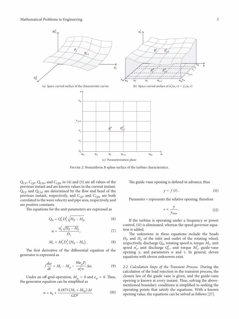
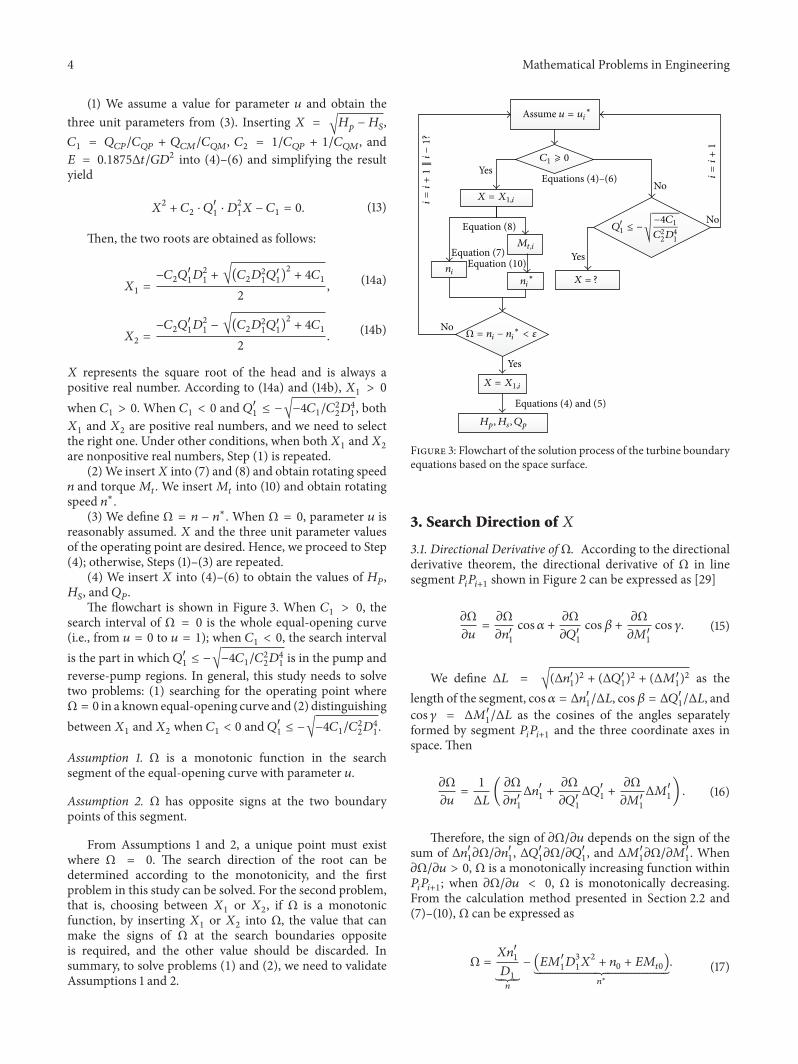
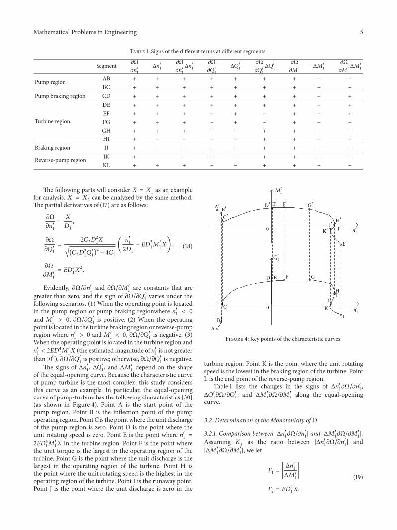
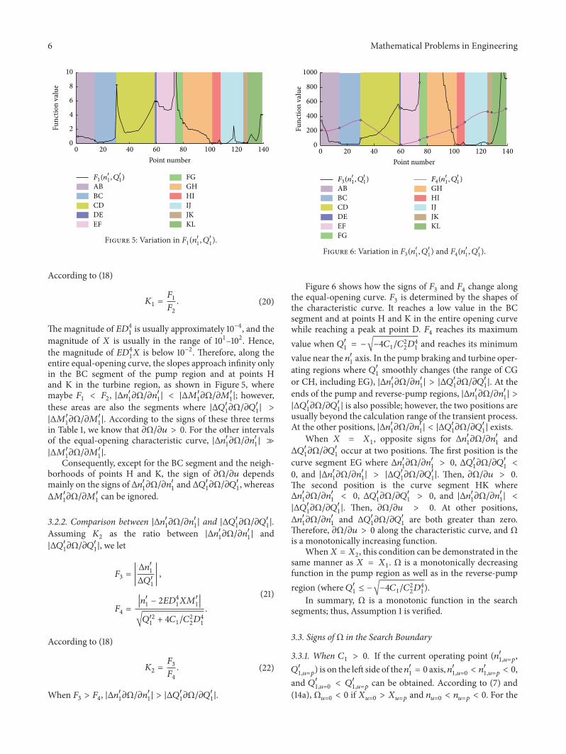
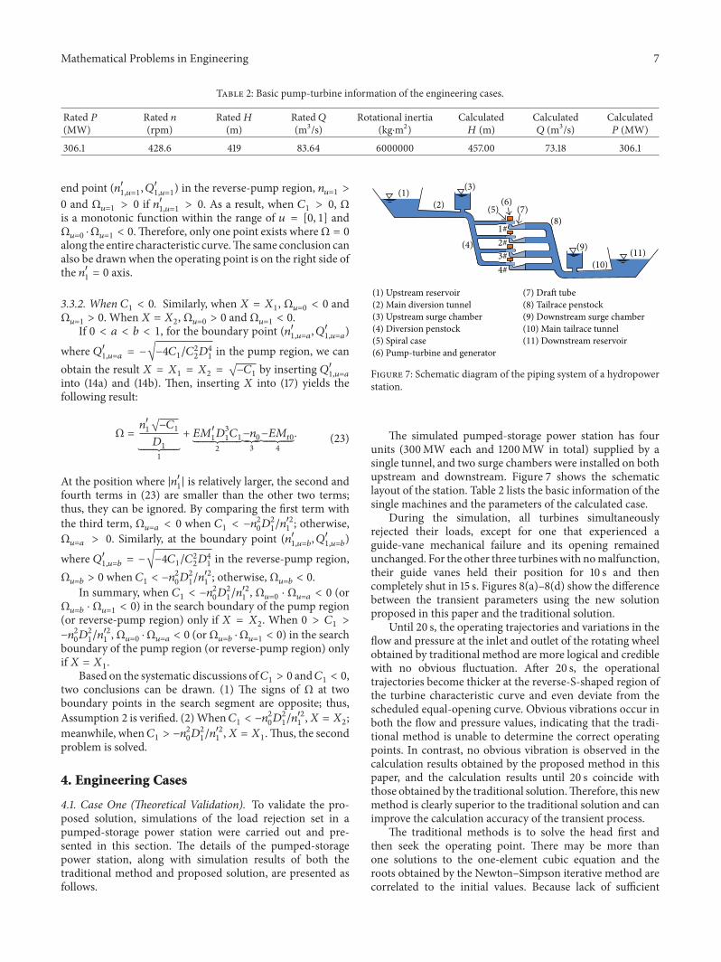
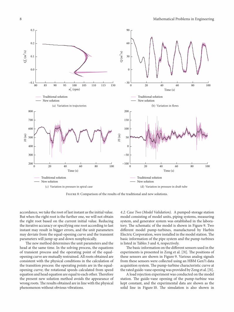
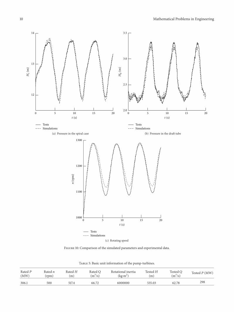