Research Article Synergetic Effects of Mechanical ...
10
Research Article Synergetic Effects of Mechanical Properties on Graphene Nanoplatelet and Multiwalled Carbon Nanotube Hybrids Reinforced Epoxy/Carbon Fiber Composites Pin-Ning Wang, 1 Tsung-Han Hsieh, 2 Chin-Lung Chiang, 3 and Ming-Yuan Shen 4 1 Department of Creative Fashion Design, Taoyuan Innovation Institute of Technology, Jhongli, Taoyuan 32091, Taiwan 2 Department of Mold and Die Engineering, National Kaohsiung University of Applied Science, Kaohsiung 80778, Taiwan 3 Department of Safety, Health and Environmental Engineering, Hung Kuang University, Taichung 43302, Taiwan 4 Department of Aviation Mechanical Engineering, China University of Science and Technology, Hsinchu 31241, Taiwan Correspondence should be addressed to Ming-Yuan Shen; [email protected] Received 24 September 2014; Revised 11 January 2015; Accepted 12 January 2015 Academic Editor: Myoung-Woon Moon Copyright © 2015 Pin-Ning Wang et al. is is an open access article distributed under the Creative Commons Attribution License, which permits unrestricted use, distribution, and reproduction in any medium, provided the original work is properly cited. Graphene nanoplatelets (GNPs) and carbon nanotubes (CNTs) are novel nanofillers possessing attractive characteristics, including robust compatibility with most polymers, high absolute strength, and cost effectiveness. In this study, an outstanding synergetic effect on the grapheme nanoplatelets (GNPs) and multiwalled carbon nanotubes (CNTs) hybrids were used to reinforce epoxy composite and epoxy/carbon fiber composite laminates to enhance their mechanical properties. e mechanical properties of CNTs/GNPs hybrids on a fixed weight fraction (1 wt%) with mixing different ratio reinforced epoxy nanocomposite, such as ultimate tensile strength and flexure properties, were investigated. e mechanical properties of epoxy/carbon fiber composite laminates containing different proportions of CNTs/GNPs hybrids (0.5, 1.0, 1.5 wt%) were increased over that of neat laminates. Consequently, significant improvement in the mechanical properties was attained for these epoxy resin composites and carbon fiber-reinforced epoxy composite laminates. 1. Introduction CNTs are one-dimensional carbon nanomaterials that pos- sess high strength, high flexibility, low mass density, and large aspect ratio [1]. CNTs have a unique combination of mechan- ical, electrical, and thermal properties that render them excel- lent candidates to substitute or complement conventional nanofillers in fabricating multifunctional polymer nanocom- posites [2–4]. However, the development of CNT reinforced polymer nanocomposites has been impeded by their cost and aggregation in polymer matrix. CNTs tend to agglomerate due to their large aspect ratio and Van der Waals forces, which leads to their dispersion difficultly in polymer matrix [5]. e GNPs planar structure provides a two-dimensional path for phonon transport, and the ultrahigh surface area allows a large surface contact area with polymer resulting in enhancement of the composite thermal conductivity [6–8]. However, the large surface area between GNPs which is GNP planar nanosheets results in large Van der Waals forces and strong - interactions [9–11]. us, the performance of GNPs based polymer composites is limited by the aggregation and stacking of GNP sheets. Since the physicochemical properties of aggregated GNPs are similar to those of graphite with its relatively low-specific surface area, the performance of GNPs will suffer significantly from reduced performance. is is an important issue if GNPs potential as a polymer composite reinforcing materials is realized [12, 13]. Epoxy is widely applied in advanced carbon fiber rein- force plastic (CFRP) due to their good mechanical perfor- mance, process-ability, compatibility with most fibers, chem- ical resistance, wear resistance, and low cost. However, these materials are relatively brittle, which is detrimental to the interlaminar properties between matrix and reinforcement. e addition of CNTs or GNPs to improve the interfacial Hindawi Publishing Corporation Journal of Nanomaterials Volume 2015, Article ID 838032, 9 pages http://dx.doi.org/10.1155/2015/838032
Transcript of Research Article Synergetic Effects of Mechanical ...
Research ArticleSynergetic Effects of Mechanical Properties on GrapheneNanoplatelet and Multiwalled Carbon Nanotube HybridsReinforced Epoxy/Carbon Fiber Composites
Pin-Ning Wang,1 Tsung-Han Hsieh,2 Chin-Lung Chiang,3 and Ming-Yuan Shen4
1Department of Creative Fashion Design, Taoyuan Innovation Institute of Technology, Jhongli, Taoyuan 32091, Taiwan2Department of Mold and Die Engineering, National Kaohsiung University of Applied Science, Kaohsiung 80778, Taiwan3Department of Safety, Health and Environmental Engineering, Hung Kuang University, Taichung 43302, Taiwan4Department of Aviation Mechanical Engineering, China University of Science and Technology, Hsinchu 31241, Taiwan
Correspondence should be addressed to Ming-Yuan Shen; [email protected]
Received 24 September 2014; Revised 11 January 2015; Accepted 12 January 2015
Academic Editor: Myoung-Woon Moon
Copyright © 2015 Pin-Ning Wang et al.This is an open access article distributed under the Creative Commons Attribution License,which permits unrestricted use, distribution, and reproduction in any medium, provided the original work is properly cited.
Graphene nanoplatelets (GNPs) and carbon nanotubes (CNTs) are novel nanofillers possessing attractive characteristics, includingrobust compatibility with most polymers, high absolute strength, and cost effectiveness. In this study, an outstanding synergeticeffect on the grapheme nanoplatelets (GNPs) and multiwalled carbon nanotubes (CNTs) hybrids were used to reinforce epoxycomposite and epoxy/carbon fiber composite laminates to enhance their mechanical properties. The mechanical properties ofCNTs/GNPshybrids on a fixedweight fraction (1 wt%)withmixing different ratio reinforced epoxynanocomposite, such as ultimatetensile strength and flexure properties, were investigated. The mechanical properties of epoxy/carbon fiber composite laminatescontaining different proportions of CNTs/GNPs hybrids (0.5, 1.0, 1.5 wt%) were increased over that of neat laminates. Consequently,significant improvement in the mechanical properties was attained for these epoxy resin composites and carbon fiber-reinforcedepoxy composite laminates.
1. Introduction
CNTs are one-dimensional carbon nanomaterials that pos-sess high strength, high flexibility, lowmass density, and largeaspect ratio [1]. CNTs have a unique combination of mechan-ical, electrical, and thermal properties that render them excel-lent candidates to substitute or complement conventionalnanofillers in fabricating multifunctional polymer nanocom-posites [2–4]. However, the development of CNT reinforcedpolymer nanocomposites has been impeded by their cost andaggregation in polymer matrix. CNTs tend to agglomeratedue to their large aspect ratio andVan derWaals forces, whichleads to their dispersion difficultly in polymer matrix [5].
The GNPs planar structure provides a two-dimensionalpath for phonon transport, and the ultrahigh surface areaallows a large surface contact area with polymer resulting inenhancement of the composite thermal conductivity [6–8].
However, the large surface area between GNPs which is GNPplanar nanosheets results in large Van der Waals forces andstrong 𝜋-𝜋 interactions [9–11]. Thus, the performance ofGNPs based polymer composites is limited by the aggregationand stacking of GNP sheets. Since the physicochemicalproperties of aggregatedGNPs are similar to those of graphitewith its relatively low-specific surface area, the performanceof GNPs will suffer significantly from reduced performance.This is an important issue if GNPs potential as a polymercomposite reinforcing materials is realized [12, 13].
Epoxy is widely applied in advanced carbon fiber rein-force plastic (CFRP) due to their good mechanical perfor-mance, process-ability, compatibility with most fibers, chem-ical resistance, wear resistance, and low cost. However, thesematerials are relatively brittle, which is detrimental to theinterlaminar properties between matrix and reinforcement.The addition of CNTs or GNPs to improve the interfacial
Hindawi Publishing CorporationJournal of NanomaterialsVolume 2015, Article ID 838032, 9 pageshttp://dx.doi.org/10.1155/2015/838032
2 Journal of Nanomaterials
Vacuum heating ovenHot press moldingGNPs/CNTs/epoxy/carbonfiber
Impregnation of carbon fiber fabric with epoxyVacuum heating oven13 plies of prepregs Hot press molding
GNPs/epoxy composite
Flexure
TEM
Flexure
(b)
(c)
Homogenizer stirring
MEK
Ultrasonication
Epoxy resin
Mechanical mixer
(a)
MWCNTsHybrids:
ILSS
SEM
Tensile
SEM
GNPs
resin (prepreg)
300mm
300mm
300
mm
300
mm
10 : 0, 9 : 1, 7 : 3, 5 : 5, 3 : 7, 1 : 9 : 10, 0
Hybrids: 1wt%
CNTs : GNPs =
0, 0.5, 1.0, 1.5wt%(CNTs : GNPs = 1 : 9)
GIC
laminate
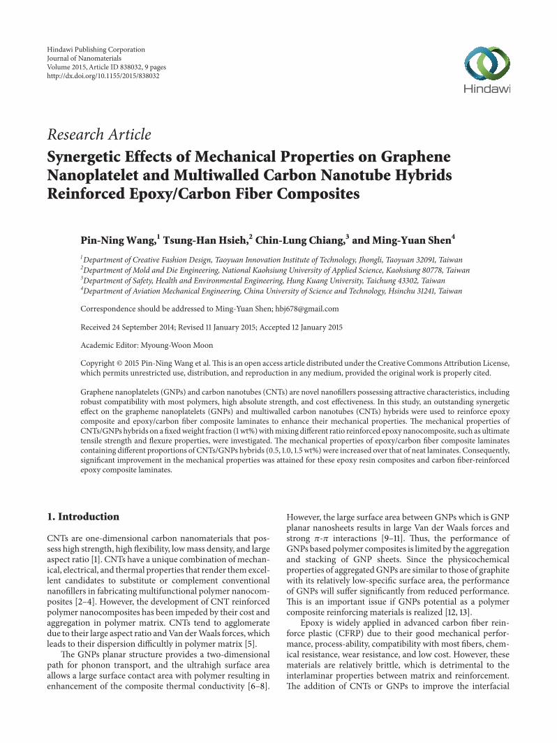
Figure 1: A schematic illustration of the fabrication of composites: (a) CNTs/GNPs/epoxy resin solution; (b) CNTs/GNPs/epoxynanocomposites; (c) CNTs/GNPs/epoxy/carbon fiber composite laminates.
strength of laminates has been demonstrated. Adding carbonbase nanofillers, such as CNTs and GNPs, can improvemechanical properties of polymer composites, due to theirunique nanostructures, and superior properties.
In our previous research [14], GNPs were used to rein-force epoxy composite and epoxy/carbon fiber compos-ite laminates to enhance their mechanical properties. Themechanical properties of GNPs/epoxy nanocomposite, suchas ultimate tensile strength and flexure properties, wereinvestigated.
To the best of our knowledge, very few studies haveso far been reported on the fabrication of CNTs/GNPshybrids reinforced CFRP composites using manufacturingof prepregs [15]. GNPs and CNTs are difficult to processbecause of the issues associated with agglomeration andlack of interfacial interactions with polymers. None of theprevious studies, nevertheless, have given due attention tothe influence of adding CNTs/GNPs hybrids on the solventtype prepreg process.Therefore, it is necessary to understandthe role of adding CNTs/GNPs hybrids into the polymermatrix, which will largely affect the impregnation of fibresand prepreg processing conditions.
In this study, epoxy resin containing uniformly dispersed1 wt% CNTs/GNPs hybrids with different mixing ratio (i.e.,10 : 0, 9 : 1, 7 : 3, 5 : 5, 3 : 7, 1 : 9, and 0 : 10) and prepared theCNTs/GNPs/epoxy nanocomposites. Mechanical propertiesof the nanocomposite, including ultimate tensile strength,flexural strength, and flexural modulus, were investigated.
The solution of epoxy resin containing the fixed mixingratio of CNTs/GNPs hybrids (1 : 9) on the different contents(i.e., 0, 0.5, 1.0, and 1.5 wt%) permeate through a carbon fibercloth was used to prepare the epoxy/carbon fiber compositelaminates.The process was used to investigate if CNTs/GNPshybrids improved the mechanical properties of carbon fiber-reinforced epoxy resin composite laminates.
Finally, the fracture surface of the specimen was inves-tigated using scanning electron microscopy (SEM) andtransmission electron microscopy (TEM) to determine therole of adding CNTs/GNPs hybrids into the epoxy andepoxy/carbon fibers composite laminates.
2. Experimental
2.1. Preparation of CNTs/GNPs/Epoxy Resin Solution. Themaleic anhydride, MA, was used to modify carbon nano-materials. Graphene nanoplatelets, GNPs with a thicknessof 5–25 nm are obtained from Xiamen Knano GrapheneTechnology Co., Ltd. China. Multiwalled carbon nanotubes,CNTs, with 1–25𝜇m in length and 20 nm in diameter areobtained from Nanocyl Co., Ltd. Belgium. The GNPs andCNTs were modified by Hanyu Material Co., Ltd. Taiwan.The CNTs/GNPs hybrids were used for reinforcement in thisstudy. The CNTs/GNPs/methyl ethyl ketone (MEK) solutionwas stirred for 10 minutes using a homogenizer. The solutionwas then vibrated by ultrasonication for 90 minutes to enablethe CNTs/GNPs hybrids to disperse uniformly throughoutthe MEK solution. The CNTs/GNPs/MEK solution wasmixed with epoxy resin and hardener (EPO-622 epoxy resinand 2-ethyl-4-methylimidazole hardener, Epotech Compos-ite Co., Ltd, Taiwan) for 90minutes using amechanical stirrerand then vibrated by ultrasonication for 90 minutes to enablethe CNTs/GNPs hybrids to disperse uniformly throughoutthe epoxy solution. A schematic illustration of the fabricationof the CNTs/GNPs/epoxy resin is shown in Figure 1(a).
2.2. Preparation of CNTs/GNPs/Epoxy Nanocomposites. TheCNTs/GNPs/epoxy resin solution was placed in a heatingoven for exposure at 83∘C for three hours to evaporateall of the solvent and then placed in a vacuum heatingoven and vacuum pumping was performed for 5 minutes

Journal of Nanomaterials 3
to eliminate air bubbles. The resin solution was poured intomolds and then placed on a hot press machine to form theCNTs/GNPs/epoxy nanocomposites (pressed at 1500 psi and150∘C for 30 minutes).The nanocomposites were then placedin a heating oven at 140∘C for 3 hours to eliminate the internalstress (postcure). A schematic illustration of the fabrica-tion of the CNTs/GNPs/epoxy nanocomposite is shown inFigure 1(b).
2.3. Preparation of CNTs/GNPs/Epoxy/Carbon FiberComposite Laminates
2.3.1. Impregnation of Carbon Fiber Fabric with EpoxyResin (Prepreg). A piece of 3 k carbon fiber fabric of thedesired dimensions was placed on a release paper and theMEK/CNTs/GNPs/epoxy resin solution was evenly perme-ated on it. The carbon fiber fabric with uniformly dispersedMEK/CNTs/GNPs/epoxy resin (prepreg) was then placedin a heating oven for exposure at 83∘C for three hours toevaporate all of the solvent.
2.3.2. Hot Press Molding and Postcuring. Thirteen pieces ofprepregs were piled in a mold and placed on a hot pressmachine to prepare a CNTs/GNPs/epoxy/carbon fiber com-posite laminate (pressed at 1500 psi and 150∘C for 30mins).The composite laminate was then placed in a heating ovenat 140∘C for three hours to eliminate the internal stressof laminate (postcure) [16]. A schematic illustration of thefabrication of the composite laminate is shown in Figure 1(c).
2.4. Experimental Process
2.4.1. Experimental Process of CNTs/GNPs/Epoxy Nanocom-posites. CNTs/GNPs hybrids reinforced epoxy nanocompos-ites containing the fixed weight fraction of CNTs/GNPshybrids (1 wt%) with different mixing ratio (i.e., 10 : 0, 9 : 1,7 : 3, 5 : 5, 3 : 7, 1 : 9, and 0 : 10) were fabricated.Themechanicalproperties of the nanocomposites, such as ultimate tensilestrength, flexural strength, and flexural modulus, were inves-tigated.
The fracture surface of the specimen was investigatedusing transmission electron microscopy (TEM) and fieldemission scanning electron microscopy (FESEM) to deter-mine the dispersion of the CNTs/GNPs hybrids in thenanocomposites.
2.4.2. Experimental Process of Composite Laminates. CNTs/GNPs hybrids reinforced epoxy/carbon fiber composite lami-nates containing the fixedmixing ratio (1 : 9) and adding threeproportions of CNTs/GNPs hybrids (i.e., 0.5, 1.0, and 1.5 wt%)were fabricated. The mechanical properties of the compositelaminates, such as flexure properties and interlaminar shearstrength, ILSS, were investigated. A double cantilever beam(DCB) specimen was employed using corrected beam theory(CBT) method for calculating 𝐺IC (Mode I) in order todetermine interlaminar fracture toughness evaluation ofcomposite laminates without and with CNTs/GNPs hybridsadded.
Piano hinge PTFE
W
t
500mm
Figure 2: The schematic representation of the DCB specimen forMode I (𝐺IC) test.
The fracture surface of the specimens was investigatedusing SEM to determine if the CNTs/GNPs hybrids wouldprevent the formation of pores in the laminates and makesCNTs/GNPs hybrids effective in delivering stress to improvethe mechanical properties of composite laminates.
2.4.3. 𝐺𝐼𝐶
Test of Composite Laminates. Double cantileverbeam (DCB) tests were used to determine the fractureresistant under Mode I opening load, in which Mode Idelamination fracture energy, 𝐺IC, can be followed from theBritish Standard, BS7991:2001. Specimen geometries werecontrolled to be 165mm long beams with a 20mm widthand 3mm thick. The specimen was prepared with a prein-serted starter crack by a 60 𝜇m thick nonstick film madeof polytetrafluoroethylene (PTFE) to make a delaminationlength of 50mm from load line, as shown in Figure 2. Twosteel-alloy loading-piano hinges were bonded on either sideof the specimen. DCB tests require that load, displacement,and crack length measurements are taken. To compare the𝐺IC of various amounts of CNTs/GNPs hybrids reinforcedepoxy/carbon fiber composite laminates, the𝐺IC when stablecrack growth reached 50mm from the load line (i.e., the endof insert PTFE precrack) was designated as the initial 𝐺ICvalue (𝐺IC-init). 𝐺IC-init was used to analyze the influenceof mixed carbon nanomaterials on the fracture toughness ofepoxy resin/carbon fiber composite laminates.𝐺IC was initially calculated by using the area method
[17], which represents the area under the load-displacementcurve. Area method is based on linear fracture mechanicssimple beam theory, which assumes a perfectly built-in DCBspecimen:
𝐺IC =3𝑃𝛿
2𝑏𝑎
, (1)
where 𝑃 is the load (𝑁), 𝛿 is the crack opening displace-ment (mm), 𝑏 is the specimen width (mm), and 𝑎 is thedelamination length (mm). However, this underestimates thecompliance (𝐶 = 𝛿/𝑃) as the beam is not perfectly built-in.A means of correcting this effect is to apply a slightly longerdelamination length of𝛼+|Δ|.The |Δ| is found experimentallyby plotting the cube root of compliance (𝐶1/3) againstdelamination length (𝛼). The extrapolation of a linear fitthrough data yields Δ as the 𝑥-axis intercept.
4 Journal of Nanomaterials
O OO
C C
O
C OC
OH
OC C
OHC O
O
CO
C
HO
COH
+
+
Figure 3: Reaction of maleic anhydride and epoxide group.
The delamination propagation values from Mode I pre-crack were used for the linear fit data. In addition, largedisplacement correction (𝐹) was applied for all specimens,which contributed significantly if the 𝛿/𝑝 ratio was largerthan 0.4. This method of calculating 𝐺IC is known as cor-rected beam theory (CBT). All initiation and propagationvalues were calculated according to
𝐺IC =3𝑃𝛿
2𝑏 (𝑎 + |Δ|)
𝐹. (2)
3. Results and Discussion
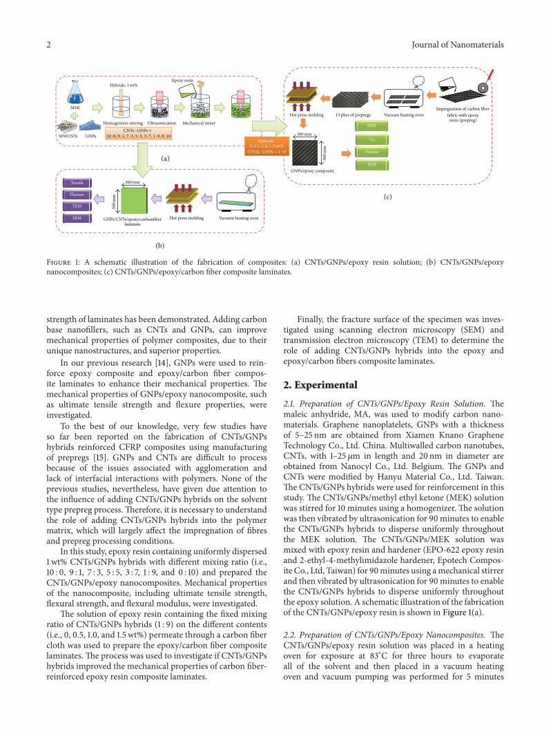
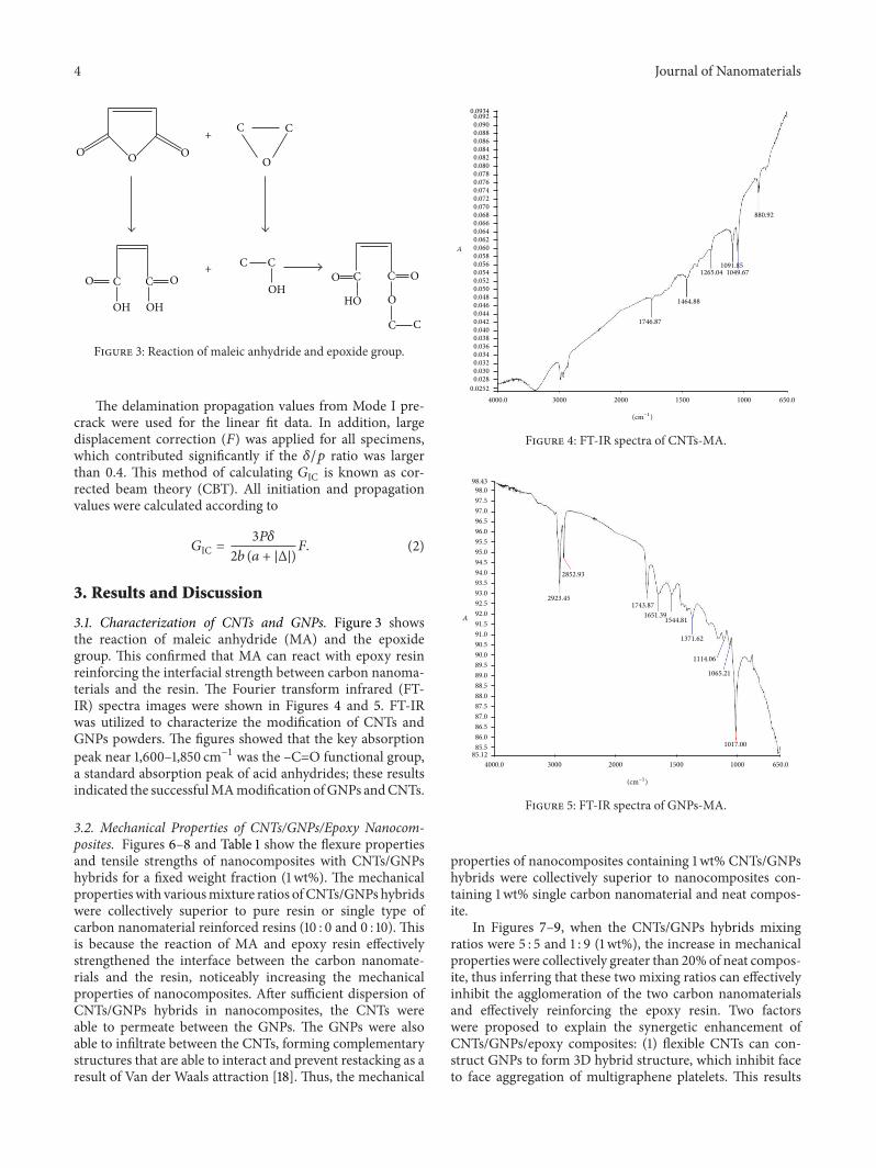
3.1. Characterization of CNTs and GNPs. Figure 3 showsthe reaction of maleic anhydride (MA) and the epoxidegroup. This confirmed that MA can react with epoxy resinreinforcing the interfacial strength between carbon nanoma-terials and the resin. The Fourier transform infrared (FT-IR) spectra images were shown in Figures 4 and 5. FT-IRwas utilized to characterize the modification of CNTs andGNPs powders. The figures showed that the key absorptionpeak near 1,600–1,850 cm−1 was the –C=O functional group,a standard absorption peak of acid anhydrides; these resultsindicated the successfulMAmodification ofGNPs andCNTs.
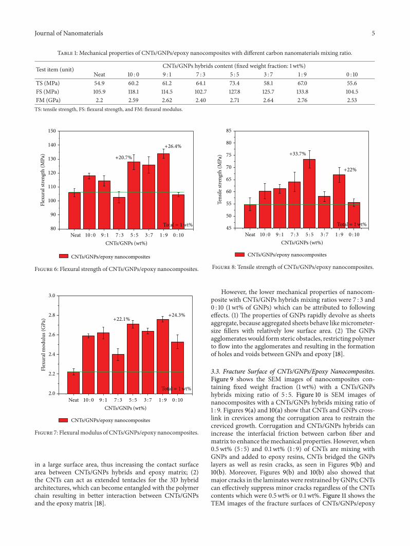
3.2. Mechanical Properties of CNTs/GNPs/Epoxy Nanocom-posites. Figures 6–8 and Table 1 show the flexure propertiesand tensile strengths of nanocomposites with CNTs/GNPshybrids for a fixed weight fraction (1 wt%). The mechanicalpropertieswith variousmixture ratios of CNTs/GNPs hybridswere collectively superior to pure resin or single type ofcarbon nanomaterial reinforced resins (10 : 0 and 0 : 10). Thisis because the reaction of MA and epoxy resin effectivelystrengthened the interface between the carbon nanomate-rials and the resin, noticeably increasing the mechanicalproperties of nanocomposites. After sufficient dispersion ofCNTs/GNPs hybrids in nanocomposites, the CNTs wereable to permeate between the GNPs. The GNPs were alsoable to infiltrate between the CNTs, forming complementarystructures that are able to interact and prevent restacking as aresult of Van der Waals attraction [18]. Thus, the mechanical
0.09340.0920.0900.0880.0860.0840.0820.0800.0780.0760.0740.0720.0700.0680.0660.0640.0620.0600.0580.0560.0540.0520.0500.0480.0460.0440.0420.0400.0380.0360.0340.0320.0300.028
0.02524000.0 3000 2000 1500 1000 650.0
880.92
1049.671265.041091.85
1464.88
1746.87
A
(cm−1)
Figure 4: FT-IR spectra of CNTs-MA.
98.4398.097.597.096.596.095.595.094.594.093.593.092.592.091.591.090.590.089.589.088.588.087.587.086.586.085.5
85.124000.0 3000 2000 1500 1000 650.0
2923.45
2852.93
1743.871651.39
1544.81
1371.62
1114.06
1065.21
1017.00
(cm−1)
A
Figure 5: FT-IR spectra of GNPs-MA.
properties of nanocomposites containing 1 wt% CNTs/GNPshybrids were collectively superior to nanocomposites con-taining 1 wt% single carbon nanomaterial and neat compos-ite.
In Figures 7–9, when the CNTs/GNPs hybrids mixingratios were 5 : 5 and 1 : 9 (1 wt%), the increase in mechanicalproperties were collectively greater than 20% of neat compos-ite, thus inferring that these two mixing ratios can effectivelyinhibit the agglomeration of the two carbon nanomaterialsand effectively reinforcing the epoxy resin. Two factorswere proposed to explain the synergetic enhancement ofCNTs/GNPs/epoxy composites: (1) flexible CNTs can con-struct GNPs to form 3D hybrid structure, which inhibit faceto face aggregation of multigraphene platelets. This results
Journal of Nanomaterials 5
Table 1: Mechanical properties of CNTs/GNPs/epoxy nanocomposites with different carbon nanomaterials mixing ratio.
Test item (unit) CNTs/GNPs hybrids content (fixed weight fraction: 1 wt%)Neat 10 : 0 9 : 1 7 : 3 5 : 5 3 : 7 1 : 9 0 : 10
TS (MPa) 54.9 60.2 61.2 64.1 73.4 58.1 67.0 55.6FS (MPa) 105.9 118.1 114.5 102.7 127.8 125.7 133.8 104.5FM (GPa) 2.2 2.59 2.62 2.40 2.71 2.64 2.76 2.53TS: tensile strength, FS: flexural strength, and FM: flexural modulus.
Neat80
90
100
110
120
130
140
150
Flex
ural
stre
ngth
(MPa
)
CNTs/GNPs (wt%)
CNTs/GNPs/epoxy nanocomposites
10 : 0 9 : 1 7 : 3 5 : 5 3 : 7 1 : 9 0 : 10
+26.4%
+20.7%
Total = 1wt%
Figure 6: Flexural strength of CNTs/GNPs/epoxy nanocomposites.
Neat2.0
2.2
2.4
2.6
2.8
3.0
Flex
ural
mod
ulus
(GPa
)
CNTs/GNPs (wt%)
CNTs/GNPs/epoxy nanocomposites
10 : 0 9 : 1 7 : 3 5 : 5 3 : 7 1 : 9 0 : 10
+24.3%+22.1%
Total = 1wt%
Figure 7: Flexural modulus of CNTs/GNPs/epoxy nanocomposites.
in a large surface area, thus increasing the contact surfacearea between CNTs/GNPs hybrids and epoxy matrix; (2)the CNTs can act as extended tentacles for the 3D hybridarchitectures, which can become entangled with the polymerchain resulting in better interaction between CNTs/GNPsand the epoxy matrix [18].
Neat45
50
55
60
65
70
75
80
85
Tens
ile st
reng
th (M
Pa)
CNTs/GNPs (wt%)
CNTs/GNPs/epoxy nanocomposites
10 : 0 9 : 1 7 : 3 5 : 5 3 : 7 1 : 9 0 : 10
+22%
+33.7%
Total = 1wt%
Figure 8: Tensile strength of CNTs/GNPs/epoxy nanocomposites.
However, the lower mechanical properties of nanocom-posite with CNTs/GNPs hybrids mixing ratios were 7 : 3 and0 : 10 (1 wt% of GNPs) which can be attributed to followingeffects. (1) The properties of GNPs rapidly devolve as sheetsaggregate, because aggregated sheets behave likemicrometer-size fillers with relatively low surface area. (2) The GNPsagglomerateswould form steric obstacles, restricting polymerto flow into the agglomerates and resulting in the formationof holes and voids between GNPs and epoxy [18].
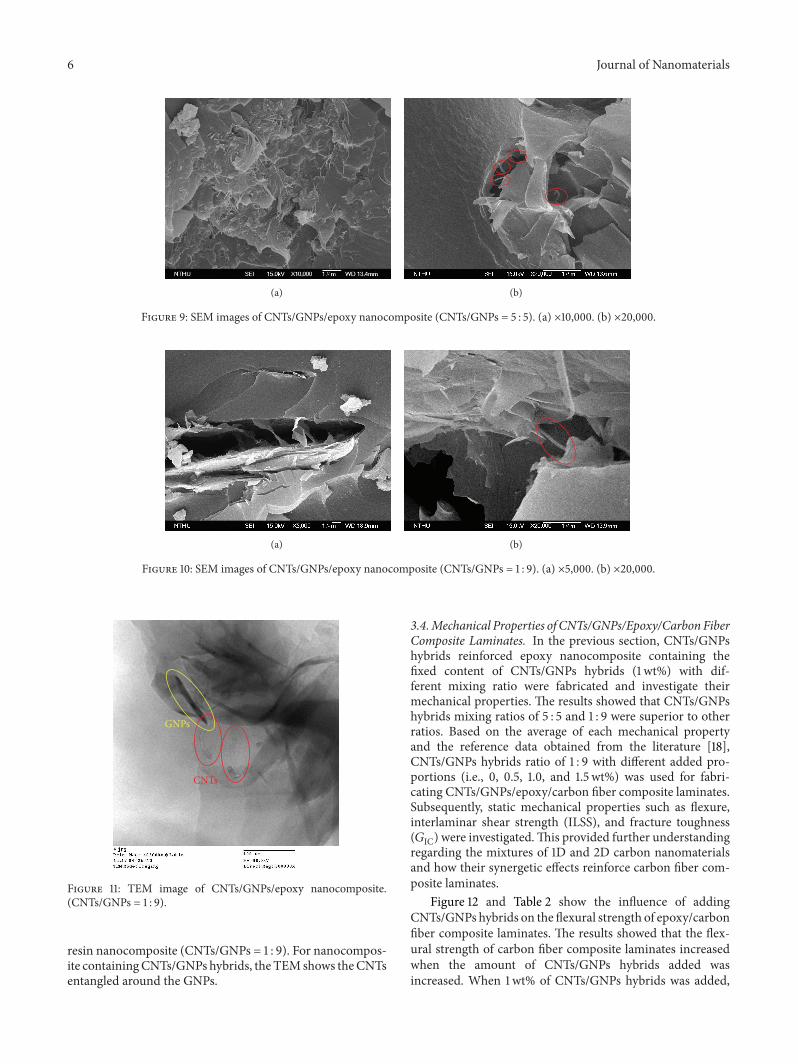
3.3. Fracture Surface of CNTs/GNPs/Epoxy Nanocomposites.Figure 9 shows the SEM images of nanocomposites con-taining fixed weight fraction (1 wt%) with a CNTs/GNPshybrids mixing ratio of 5 : 5. Figure 10 is SEM images ofnanocomposites with a CNTs/GNPs hybrids mixing ratio of1 : 9. Figures 9(a) and 10(a) show that CNTs and GNPs cross-link in crevices among the corrugation area to restrain thecreviced growth. Corrugation and CNTs/GNPs hybrids canincrease the interfacial friction between carbon fiber andmatrix to enhance themechanical properties. However, when0.5 wt% (5 : 5) and 0.1 wt% (1 : 9) of CNTs are mixing withGNPs and added to epoxy resins, CNTs bridged the GNPslayers as well as resin cracks, as seen in Figures 9(b) and10(b). Moreover, Figures 9(b) and 10(b) also showed thatmajor cracks in the laminates were restrained byGNPs; CNTscan effectively suppress minor cracks regardless of the CNTscontents which were 0.5 wt% or 0.1 wt%. Figure 11 shows theTEM images of the fracture surfaces of CNTs/GNPs/epoxy
6 Journal of Nanomaterials
(a) (b)
Figure 9: SEM images of CNTs/GNPs/epoxy nanocomposite (CNTs/GNPs = 5 : 5). (a) ×10,000. (b) ×20,000.
(a) (b)
Figure 10: SEM images of CNTs/GNPs/epoxy nanocomposite (CNTs/GNPs = 1 : 9). (a) ×5,000. (b) ×20,000.
GNPs
CNTs
Figure 11: TEM image of CNTs/GNPs/epoxy nanocomposite.(CNTs/GNPs = 1 : 9).
resin nanocomposite (CNTs/GNPs = 1 : 9). For nanocompos-ite containingCNTs/GNPs hybrids, the TEMshows theCNTsentangled around the GNPs.
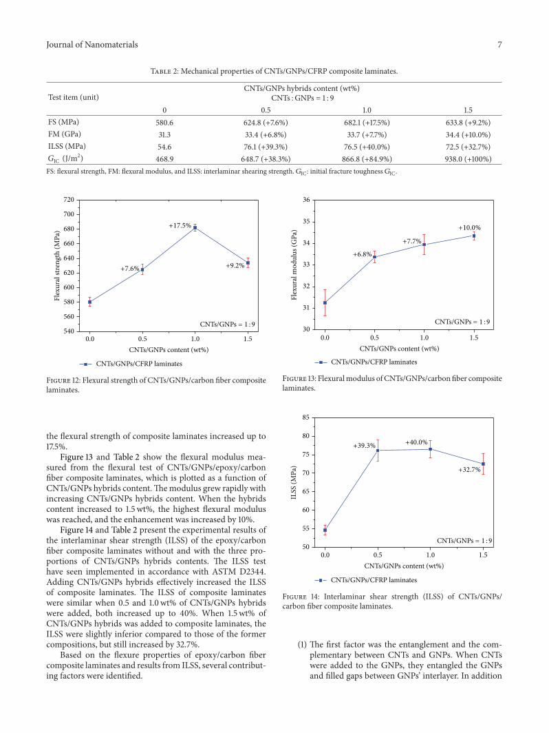
3.4.Mechanical Properties of CNTs/GNPs/Epoxy/Carbon FiberComposite Laminates. In the previous section, CNTs/GNPshybrids reinforced epoxy nanocomposite containing thefixed content of CNTs/GNPs hybrids (1 wt%) with dif-ferent mixing ratio were fabricated and investigate theirmechanical properties. The results showed that CNTs/GNPshybrids mixing ratios of 5 : 5 and 1 : 9 were superior to otherratios. Based on the average of each mechanical propertyand the reference data obtained from the literature [18],CNTs/GNPs hybrids ratio of 1 : 9 with different added pro-portions (i.e., 0, 0.5, 1.0, and 1.5 wt%) was used for fabri-cating CNTs/GNPs/epoxy/carbon fiber composite laminates.Subsequently, static mechanical properties such as flexure,interlaminar shear strength (ILSS), and fracture toughness(𝐺IC)were investigated.This provided further understandingregarding the mixtures of 1D and 2D carbon nanomaterialsand how their synergetic effects reinforce carbon fiber com-posite laminates.
Figure 12 and Table 2 show the influence of addingCNTs/GNPs hybrids on the flexural strength of epoxy/carbonfiber composite laminates. The results showed that the flex-ural strength of carbon fiber composite laminates increasedwhen the amount of CNTs/GNPs hybrids added wasincreased. When 1wt% of CNTs/GNPs hybrids was added,
Journal of Nanomaterials 7
Table 2: Mechanical properties of CNTs/GNPs/CFRP composite laminates.
Test item (unit)CNTs/GNPs hybrids content (wt%)
CNTs : GNPs = 1 : 90 0.5 1.0 1.5
FS (MPa) 580.6 624.8 (+7.6%) 682.1 (+17.5%) 633.8 (+9.2%)FM (GPa) 31.3 33.4 (+6.8%) 33.7 (+7.7%) 34.4 (+10.0%)ILSS (MPa) 54.6 76.1 (+39.3%) 76.5 (+40.0%) 72.5 (+32.7%)𝐺IC (J/m2) 468.9 648.7 (+38.3%) 866.8 (+84.9%) 938.0 (+100%)FS: flexural strength, FM: flexural modulus, and ILSS: interlaminar shearing strength. 𝐺IC: initial fracture toughness 𝐺IC.
0.0 0.5 1.0 1.5540
560
580
600
620
640
660
680
700
720
Flex
ural
stre
ngth
(MPa
)
CNTs/GNPs content (wt%)
CNTs/GNPs/CFRP laminates
+9.2%
+17.5%
CNTs/GNPs = 1 : 9
+7.6%
Figure 12: Flexural strength of CNTs/GNPs/carbon fiber compositelaminates.
the flexural strength of composite laminates increased up to17.5%.
Figure 13 and Table 2 show the flexural modulus mea-sured from the flexural test of CNTs/GNPs/epoxy/carbonfiber composite laminates, which is plotted as a function ofCNTs/GNPs hybrids content.Themodulus grew rapidly withincreasing CNTs/GNPs hybrids content. When the hybridscontent increased to 1.5 wt%, the highest flexural moduluswas reached, and the enhancement was increased by 10%.
Figure 14 and Table 2 present the experimental results ofthe interlaminar shear strength (ILSS) of the epoxy/carbonfiber composite laminates without and with the three pro-portions of CNTs/GNPs hybrids contents. The ILSS testhave seen implemented in accordance with ASTM D2344.Adding CNTs/GNPs hybrids effectively increased the ILSSof composite laminates. The ILSS of composite laminateswere similar when 0.5 and 1.0 wt% of CNTs/GNPs hybridswere added, both increased up to 40%. When 1.5 wt% ofCNTs/GNPs hybrids was added to composite laminates, theILSS were slightly inferior compared to those of the formercompositions, but still increased by 32.7%.
Based on the flexure properties of epoxy/carbon fibercomposite laminates and results from ILSS, several contribut-ing factors were identified.
0.0 0.5 1.0 1.530
31
32
33
34
35
36
Flex
ural
mod
ulus
(GPa
)
CNTs/GNPs content (wt%)
CNTs/GNPs/CFRP laminates
+7.7%
+10.0%
CNTs/GNPs = 1 : 9
+6.8%
Figure 13: Flexuralmodulus of CNTs/GNPs/carbon fiber compositelaminates.
0.0 0.5 1.0 1.550
55
60
65
70
75
80
85
ILSS
(MPa
)
CNTs/GNPs content (wt%)
CNTs/GNPs/CFRP laminates
+32.7%
+40.0%+39.3%
CNTs/GNPs = 1 : 9
Figure 14: Interlaminar shear strength (ILSS) of CNTs/GNPs/carbon fiber composite laminates.
(1) The first factor was the entanglement and the com-plementary between CNTs and GNPs. When CNTswere added to the GNPs, they entangled the GNPsand filled gaps between GNPs’ interlayer. In addition
8 Journal of Nanomaterials
Crack propagation GNPsCNTs
(a)
(b)
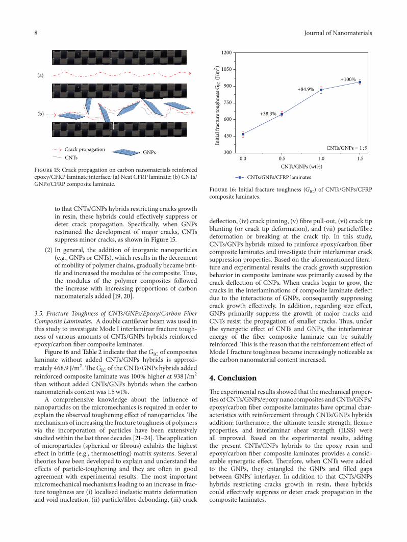
Figure 15: Crack propagation on carbon nanomaterials reinforcedepoxy/CFRP laminate interface. (a) Neat CFRP laminate; (b) CNTs/GNPs/CFRP composite laminate.
to that CNTs/GNPs hybrids restricting cracks growthin resin, these hybrids could effectively suppress ordeter crack propagation. Specifically, when GNPsrestrained the development of major cracks, CNTssuppress minor cracks, as shown in Figure 15.
(2) In general, the addition of inorganic nanoparticles(e.g., GNPs or CNTs), which results in the decrementof mobility of polymer chains, gradually became brit-tle and increased themodulus of the composite.Thus,the modulus of the polymer composites followedthe increase with increasing proportions of carbonnanomaterials added [19, 20].
3.5. Fracture Toughness of CNTs/GNPs/Epoxy/Carbon FiberComposite Laminates. A double cantilever beam was used inthis study to investigate Mode I interlaminar fracture tough-ness of various amounts of CNTs/GNPs hybrids reinforcedepoxy/carbon fiber composite laminates.
Figure 16 and Table 2 indicate that the 𝐺IC of compositeslaminate without added CNTs/GNPs hybrids is approxi-mately 468.9 J/m2.The𝐺IC of the CNTs/GNPs hybrids addedreinforced composite laminate was 100% higher at 938 J/m2than without added CNTs/GNPs hybrids when the carbonnanomaterials content was 1.5 wt%.
A comprehensive knowledge about the influence ofnanoparticles on the micromechanics is required in order toexplain the observed toughening effect of nanoparticles. Themechanisms of increasing the fracture toughness of polymersvia the incorporation of particles have been extensivelystudied within the last three decades [21–24].The applicationof microparticles (spherical or fibrous) exhibits the highesteffect in brittle (e.g., thermosetting) matrix systems. Severaltheories have been developed to explain and understand theeffects of particle-toughening and they are often in goodagreement with experimental results. The most importantmicromechanical mechanisms leading to an increase in frac-ture toughness are (i) localised inelastic matrix deformationand void nucleation, (ii) particle/fibre debonding, (iii) crack
0.0 0.5 1.0 1.5300
450
600
750
900
1050
1200
CNTs/GNPs (wt%)
CNTs/GNPs/CFRP laminates
+100%
+84.9%
+38.3%
CNTs/GNPs = 1 : 9
Initi
al fr
actu
re to
ughn
essG
IC(J
/m2)
Figure 16: Initial fracture toughness (𝐺IC) of CNTs/GNPs/CFRPcomposite laminates.
deflection, (iv) crack pinning, (v) fibre pull-out, (vi) crack tipblunting (or crack tip deformation), and (vii) particle/fibredeformation or breaking at the crack tip. In this study,CNTs/GNPs hybrids mixed to reinforce epoxy/carbon fibercomposite laminates and investigate their interlaminar cracksuppression properties. Based on the aforementioned litera-ture and experimental results, the crack growth suppressionbehavior in composite laminate was primarily caused by thecrack deflection of GNPs. When cracks begin to grow, thecracks in the interlaminations of composite laminate deflectdue to the interactions of GNPs, consequently suppressingcrack growth effectively. In addition, regarding size effect,GNPs primarily suppress the growth of major cracks andCNTs resist the propagation of smaller cracks. Thus, underthe synergetic effect of CNTs and GNPs, the interlaminarenergy of the fiber composite laminate can be suitablyreinforced. This is the reason that the reinforcement effect ofMode I fracture toughness became increasingly noticeable asthe carbon nanomaterial content increased.
4. Conclusion
The experimental results showed that themechanical proper-ties of CNTs/GNPs/epoxy nanocomposites andCNTs/GNPs/epoxy/carbon fiber composite laminates have optimal char-acteristics with reinforcement through CNTs/GNPs hybridsaddition; furthermore, the ultimate tensile strength, flexureproperties, and interlaminar shear strength (ILSS) wereall improved. Based on the experimental results, addingthe present CNTs/GNPs hybrids to the epoxy resin andepoxy/carbon fiber composite laminates provides a consid-erable synergetic effect. Therefore, when CNTs were addedto the GNPs, they entangled the GNPs and filled gapsbetween GNPs’ interlayer. In addition to that CNTs/GNPshybrids restricting cracks growth in resin, these hybridscould effectively suppress or deter crack propagation in thecomposite laminates.
Journal of Nanomaterials 9
Conflict of Interests
The authors declare that they have no conflict of interests.
Acknowledgment
This research was supported by the Ministry of Science andTechnology of Taiwan (National Science Council of Taiwan),under Grant no. MOST 103-2221-E-253-009.
References
[1] M. Moniruzzaman and K. I. Winey, “Polymer nanocompositescontaining carbon nanotubes,” Macromolecules, vol. 39, no. 16,pp. 5194–5205, 2006.
[2] Y. Li, T. Yu, T. Pui, P. Chen, L. Zheng, and K. Liao, “Fabrica-tion of transparent and conductive carbon nanotube/polyvinylbutyral films by a facile solution surface dip coating method,”Nanoscale, vol. 3, no. 6, pp. 2469–2471, 2011.
[3] T. Yu, Y. Gong, T. Lu et al., “Recognition of carbon nanotubechirality by phage display,”RSCAdvances, vol. 2, no. 4, pp. 1466–1476, 2012.
[4] Y. Li, T. Yu, T. Pui, P. Chen, L. Zheng, and K. Liao, “Fabricationand characterization of recyclable carbon nanotube/polyvinylbutyral composite fiber,” Composites Science and Technology,vol. 71, no. 14, pp. 1665–1670, 2011.
[5] Y. Li, R. Umer, A. Isakovic, Y. A. Samad, L. Zheng, and K.Liao, “Synergistic toughening of epoxy with carbon nanotubesand graphene oxide for improved long-term performance,”RSCAdvances, vol. 3, no. 23, pp. 8849–8856, 2013.
[6] A. Yu, P. Ramesh, M. E. Itkis, E. Bekyarova, and R. C. Had-don, “Graphite nanoplatelet-epoxy composite thermal interfacematerials,” Journal of Physical Chemistry C, vol. 111, no. 21, pp.7565–7569, 2007.
[7] C. Lin and D. D. L. Chung, “Graphite nanoplatelet pastes vs.carbon black pastes as thermal interface materials,”Carbon, vol.47, no. 1, pp. 295–305, 2009.
[8] M.-T. Hung, O. Choi, Y. S. Ju, andH. T. Hahn, “Heat conductionin graphite-nanoplatelet-reinforced polymer nanocomposites,”Applied Physics Letters, vol. 89, no. 2, Article ID 023117, 2006.
[9] Y. Si and E. T. Samulski, “Exfoliated graphene separated byplatinum nanoparticles,” Chemistry of Materials, vol. 20, no. 21,pp. 6792–6797, 2008.
[10] Y. Si and E. T. Samulski, “Synthesis of water soluble graphene,”Nano Letters, vol. 8, no. 6, pp. 1679–1682, 2008.
[11] D. Li, M. B. Muller, S. Gilje, R. B. Kaner, and G. G. Wallace,“Processable aqueous dispersions of graphene nanosheets,”Nature Nanotechnology, vol. 3, no. 2, pp. 101–105, 2008.
[12] M. A. Rafiee, J. Rafiee, Z. Wang, H. Song, Z.-Z. Yu, and N.Koratkar, “Enhancedmechanical properties of nanocompositesat low graphene content,” ACS Nano, vol. 3, no. 12, pp. 3884–3890, 2009.
[13] J. Li, M. L. Sham, J.-K. Kim, and G. Marom, “Morphology andproperties of UV/ozone treated graphite nanoplatelet/epoxynanocomposites,” Composites Science and Technology, vol. 67,no. 2, pp. 296–305, 2007.
[14] M.-Y. Shen, T.-Y. Chang, T.-H. Hsieh et al., “Mechanical prop-erties and tensile fatigue of graphene nanoplatelets reinforcedpolymer nanocomposites,” Journal of Nanomaterials, vol. 2013,Article ID 565401, 9 pages, 2013.
[15] T. Yokozeki, Y. Iwahori, S. Ishiwata, and K. Enomoto, “Mechan-ical properties of CFRP laminates manufactured from unidi-rectional prepregs using CSCNT-dispersed epoxy,” CompositesPart A: Applied Science and Manufacturing, vol. 38, no. 10, pp.2121–2130, 2007.
[16] B. C. Ray, “Temperature effect during humid ageing on inter-faces of glass and carbon fibers reinforced epoxy composites,”Journal of Colloid and Interface Science, vol. 298, no. 1, pp. 111–117, 2006.
[17] G. E. Morris, “Determining fracture directions and fractureorigins on failed graphite/epoxy surfaces,” in NondestructiveEvaluation and Flaw Criticality for Composite Materials, R. B.Pipes, Ed., ASTM STP 696, pp. 274–297, ASTM International,1979.
[18] S.-Y. Yang, W.-N. Lin, Y.-L. Huang et al., “Synergetic effects ofgraphene platelets and carbonnanotubes on themechanical andthermal properties of epoxy composites,” Carbon, vol. 49, no. 3,pp. 793–803, 2011.
[19] V. K. Rangari, T. A. Hassan, Q. Mayo, and S. Jeelani, “Sizereduction of WO
3
nanoparticles by ultrasound irradiationand its applications in structural nanocomposites,” CompositesScience and Technology, vol. 69, no. 14, pp. 2293–2300, 2009.
[20] R. M. Rodgers, H. Mahfuz, V. K. Rangari, N. Chisholm, andS. Jeelani, “Infusion of SiC nanoparticles into SC-15 epoxy:an investigation of thermal and mechanical response,” Macro-molecular Materials and Engineering, vol. 290, no. 5, pp. 423–429, 2005.
[21] A. C.Moloney, H. H. Kausch, T. Kaiser, andH. R. Beer, “Param-eters determining the strength and toughness of particulatefilled epoxide resins,” Journal of Materials Science, vol. 22, no.2, pp. 381–393, 1987.
[22] S. Bandyopadhyay, “Review of the microscopic and macro-scopic aspects of fracture of unmodified and modified epoxyresins,”Materials Science and Engineering A, vol. 125, no. 2, pp.157–184, 1990.
[23] D. A. Norman and R. E. Robertson, “Rigid-particle tougheningof glassy polymers,” Polymer, vol. 44, no. 8, pp. 2351–2362, 2003.
[24] B. Fiedler, F. H. Gojny, M. H. G. Wichmann, M. C. M.Nolte, andK. Schulte, “Fundamental aspects of nano-reinforcedcomposites,” Composites Science and Technology, vol. 66, no. 16,pp. 3115–3125, 2006.

Submit your manuscripts athttp://www.hindawi.com
ScientificaHindawi Publishing Corporationhttp://www.hindawi.com Volume 2014
CorrosionInternational Journal of
Hindawi Publishing Corporationhttp://www.hindawi.com Volume 2014
Polymer ScienceInternational Journal of
Hindawi Publishing Corporationhttp://www.hindawi.com Volume 2014
Hindawi Publishing Corporationhttp://www.hindawi.com Volume 2014
CeramicsJournal of
Hindawi Publishing Corporationhttp://www.hindawi.com Volume 2014
CompositesJournal of
NanoparticlesJournal of
Hindawi Publishing Corporationhttp://www.hindawi.com Volume 2014
Hindawi Publishing Corporationhttp://www.hindawi.com Volume 2014
International Journal of
Biomaterials
Hindawi Publishing Corporationhttp://www.hindawi.com Volume 2014
NanoscienceJournal of
TextilesHindawi Publishing Corporation http://www.hindawi.com Volume 2014
Journal of
NanotechnologyHindawi Publishing Corporationhttp://www.hindawi.com Volume 2014
Journal of
CrystallographyJournal of
Hindawi Publishing Corporationhttp://www.hindawi.com Volume 2014
The Scientific World JournalHindawi Publishing Corporation http://www.hindawi.com Volume 2014
Hindawi Publishing Corporationhttp://www.hindawi.com Volume 2014
CoatingsJournal of
Advances in
Materials Science and EngineeringHindawi Publishing Corporationhttp://www.hindawi.com Volume 2014
Smart Materials Research
Hindawi Publishing Corporationhttp://www.hindawi.com Volume 2014
Hindawi Publishing Corporationhttp://www.hindawi.com Volume 2014
MetallurgyJournal of
Hindawi Publishing Corporationhttp://www.hindawi.com Volume 2014
BioMed Research International
MaterialsJournal of
Hindawi Publishing Corporationhttp://www.hindawi.com Volume 2014
Nano
materials
Hindawi Publishing Corporationhttp://www.hindawi.com Volume 2014
Journal ofNanomaterials