Research Article RFID Application of Smart Grid for Asset...
7
Hindawi Publishing Corporation International Journal of Antennas and Propagation Volume 2013, Article ID 264671, 6 pages http://dx.doi.org/10.1155/2013/264671 Research Article RFID Application of Smart Grid for Asset Management Xiwei Wang, 1 Qi Dang, 1 Jinglin Guo, 1 and Hongbin Ge 2 1 Beijing China Power Information Technology Co., Ltd., State Grid Electric Power Research Institute, Haidian District, Beijing 100192, China 2 Beijing University of Posts and Telecommunications, Haidian District, Beijing 100876, China Correspondence should be addressed to Qi Dang; [email protected] Received 26 August 2013; Accepted 8 October 2013 Academic Editor: Yao Yuan Copyright © 2013 Xiwei Wang et al. is is an open access article distributed under the Creative Commons Attribution License, which permits unrestricted use, distribution, and reproduction in any medium, provided the original work is properly cited. RFID technology research has resolved practical application issues of the power industry such as assets management, working environment control, and vehicle networking. Also it provides technical reserves for the convergence of ERP and CPS. With the development of RFID and location-based services technology, RFID is converging with a variety of sensing, communication, and information technologies. Indoor positioning applications are under rapid development. Micromanagement environment of the assets is a useful practice for the RFID and positioning. In this paper, the model for RFID applications has been analyzed in the microenvironment management of the data center and electric vehicle batteries, and the optimization scheme of enterprise asset management is also proposed. 1. Introduction With the innovation of technology and applications, RFID requires a combination with other technologies and concepts of innovative design to meet the application requirements in different aspects of the management and production. In this paper, the applications and design for the intensive assets management are proposed, which are from the concrete practice of the enterprise asset management of data center equipment and electric vehicle battery: State Grid Corpora- tion data center construction and electric vehicles network construction & operation. 1.1. Overview of Application for Life Cycle Asset Management. IT Asset Management based on RFID is a priority for the asset life-cycle management framework. State Grid Corporation of China has launched the construction of the centralized disaster recovery center, the important aspect of which is condition monitoring for environments and equipment in large data center. In the construction of electric vehicle charging service network, battery asset management is an important foundation for electricity service implementation. e ultra-large-scale data centers require real-time sens- ing device status in the room and cabinet, focusing on inter- nal regional environmental management, including internal dynamic management of the device in the room, inter- nal static management of the device in the cabinet, and collaborative management of the staff. e battery device management is divided into the storage environment and external operating environment. Each battery data of the battery management system in a warehouse environment can be collected in real time. Real-time status of the battery in car, obtained by means of the vehicle terminal in the running environment, ensures regulatory convergence in the open and warehousing environments. It improves application performance based on data pro- vided by the business system as well as combining fine control of RFID technology. e application is important for changing the operating approach, enhancing management level, improving basis of operating efficiency, improving asset quality, extending equipment life, and optimizing network asset costs. 2. Proposed RFID Application Model Based on Cyber-Physical Systems Architecture Real Time Location Systems are a kind of positioning method based on radio signal, using active RFID technology. Other indoor positioning technologies include passive RFID,
Transcript of Research Article RFID Application of Smart Grid for Asset...
Hindawi Publishing CorporationInternational Journal of Antennas and PropagationVolume 2013, Article ID 264671, 6 pageshttp://dx.doi.org/10.1155/2013/264671
Research ArticleRFID Application of Smart Grid for Asset Management
Xiwei Wang,1 Qi Dang,1 Jinglin Guo,1 and Hongbin Ge2
1 Beijing China Power Information Technology Co., Ltd., State Grid Electric Power Research Institute, Haidian District,Beijing 100192, China
2 Beijing University of Posts and Telecommunications, Haidian District, Beijing 100876, China
Correspondence should be addressed to Qi Dang; [email protected]
Received 26 August 2013; Accepted 8 October 2013
Academic Editor: Yao Yuan
Copyright © 2013 Xiwei Wang et al. This is an open access article distributed under the Creative Commons Attribution License,which permits unrestricted use, distribution, and reproduction in any medium, provided the original work is properly cited.
RFID technology research has resolved practical application issues of the power industry such as assets management, workingenvironment control, and vehicle networking. Also it provides technical reserves for the convergence of ERP and CPS. With thedevelopment of RFID and location-based services technology, RFID is converging with a variety of sensing, communication, andinformation technologies. Indoor positioning applications are under rapid development. Micromanagement environment of theassets is a useful practice for the RFID and positioning. In this paper, the model for RFID applications has been analyzed in themicroenvironment management of the data center and electric vehicle batteries, and the optimization scheme of enterprise assetmanagement is also proposed.
1. Introduction
With the innovation of technology and applications, RFIDrequires a combination with other technologies and conceptsof innovative design to meet the application requirementsin different aspects of the management and production. Inthis paper, the applications and design for the intensive assetsmanagement are proposed, which are from the concretepractice of the enterprise asset management of data centerequipment and electric vehicle battery: State Grid Corpora-tion data center construction and electric vehicles networkconstruction & operation.
1.1. Overview of Application for Life Cycle Asset Management.ITAssetManagement based onRFID is a priority for the assetlife-cycle management framework. State Grid Corporationof China has launched the construction of the centralizeddisaster recovery center, the important aspect of which iscondition monitoring for environments and equipment inlarge data center. In the construction of electric vehiclecharging service network, battery asset management is animportant foundation for electricity service implementation.
The ultra-large-scale data centers require real-time sens-ing device status in the room and cabinet, focusing on inter-nal regional environmental management, including internal
dynamic management of the device in the room, inter-nal static management of the device in the cabinet, andcollaborative management of the staff. The battery devicemanagement is divided into the storage environment andexternal operating environment. Each battery data of thebattery management system in a warehouse environment canbe collected in real time. Real-time status of the battery incar, obtained by means of the vehicle terminal in the runningenvironment, ensures regulatory convergence in the openand warehousing environments.
It improves application performance based on data pro-vided by the business system as well as combining finecontrol of RFID technology. The application is important forchanging the operating approach, enhancing managementlevel, improving basis of operating efficiency, improving assetquality, extending equipment life, and optimizing networkasset costs.
2. Proposed RFID Application Model Based onCyber-Physical Systems Architecture
Real Time Location Systems are a kind of positioningmethod based on radio signal, using active RFID technology.Other indoor positioning technologies include passive RFID,
2 International Journal of Antennas and Propagation
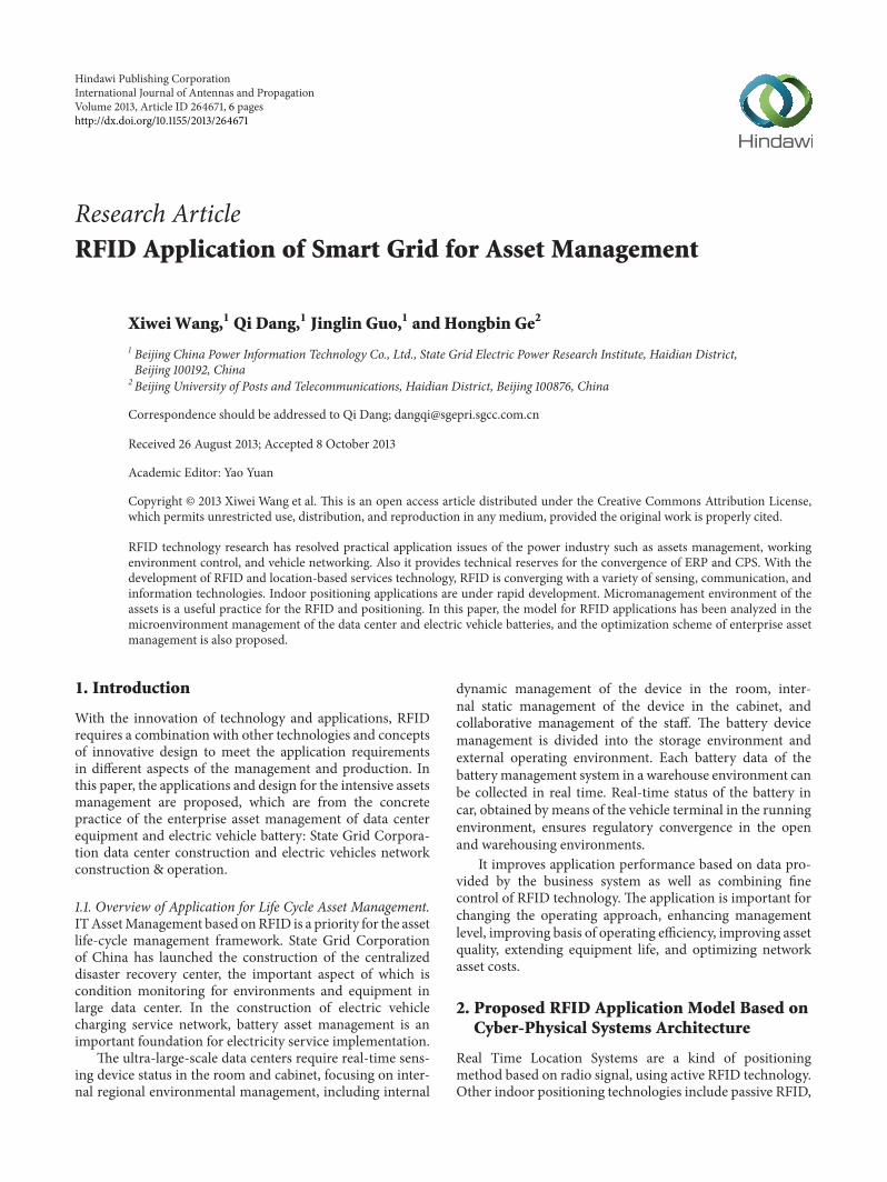
IOT
Location services
Big data
RTLS
Figure 1: RFID-based real-time location system.
Wi-Fi and UWB. The pioneering research of social network[1], complex network [2–5], big data [6–11], and cyber-physical systems (CPS) [12–16] is emerging, which changethe understanding of large-scale systems as in Figure 1 shows.CPS is the integration of computing and physical systems,which is the next generation of intelligent system to integratecomputing, communication, and control.
In practice, techniques combination and applicationinnovations can realize the effective management of assetsphysical state. Technique combinations include RTLS, RFID,and sensor technology. Application innovations guide thescheme for application through the research onRFIDapplica-tion model based on CPS architecture including acquisition,transmission, analysis, and decision making.
2.1. Proposed System Structure Model. The large enterprises’various RFID applications demand is the main factor; thusthe RFID Application Model is proposed as Figure 2 shows.The model is divided into perception, transmission, calcu-lation, control, and the supporting unit to form a completeclosed-loop system, wherein the calculating unit includes avariety of real-time processing engine. This model meets thedesign requirements of the corporate assets applications andopen environment applications.
Considering the huge amounts of data, the system needsto be configured flexible computing unit, capable of handlingmultidimensional data associated with the local real-timeprocessing, timing, and behavior change information, includ-ing the location and spatial information and flow data, as wellas the internal state and personnel state behavior. In short, thedesign model needs to meet the design requirements of thesystem in the context of the development of the Internet ofThings and big data.
Considering the location status, time and other factors,the function𝐶(𝑃,𝐻, 𝑥, 𝑦, 𝑡) of the applicationmodel is estab-lished, as shown in the formula (1). Through the associatedanalysis of the position, status, and other data within thepredetermined time, the preset rules for real-time behavioralanalysis engine are obtained as the initial conditions of themodel function. Subsequently, using the function and initial
conditions, the completeness of the information recorded isformed:𝐶 (𝑃,𝐻, 𝑥, 𝑦, 𝑡)
= 𝑃 (𝑥, 𝑦, 𝑡) + Δ𝑃 (𝑡) + 𝐻 (𝑥, 𝑦, 𝑡) + Δ𝑆 (𝑡) .
(1)
In the function, 𝑃(𝑡) represents the device location and𝐻(𝑡) represents staff position; Δ𝑃(𝑡) represents a relativeposition;Δ𝑆(𝑡) represents a change of state; (𝑥, 𝑦, 𝑡) representsthe two-dimensional position coordinates and time.
2.2. Analysis for the Comparative Model. Based on IoTapplication model, Big Data technology helps us for deeprelationship. The important difference compared to the pre-vious design is that the results and forecast information isquickly obtained through the phenomena associated withthe data analysis, and there is no need to spend too muchtime to get the answer for the problem causal association.Traditional demand models tend to seek causal association,looking for trends, cycles, and other factors in order to createthe function. For example, the user application requirementsare described through themethod of a random time series, asshown in the following formula
𝑌 (𝑡) = 𝑓 (𝑡) + 𝑝 (𝑡) + 𝑋 (𝑡) . (2)
In the formula (2), 𝑡 represents time and 𝑓(𝑡), 𝑝(𝑡) arenonrandom items. 𝑓(𝑡), the trend term, reflects the trend ofthe model 𝑌(𝑡) which is changed by linear or exponentialfunction; 𝑝(𝑡), the periodic term, reflects the cyclical changeof 𝑌(𝑡), such as year, month, day, or hour periodically;𝑋(𝑡) isa random term, which reflects the impact of various randomfactors on𝑌(𝑡).𝑋(𝑡) can be assumed to be a normal stationaryrandom process. The 𝑓(𝑡) and 𝑝(𝑡) is generally not constant,and therefore 𝑌(𝑡) is a nonstationary random process. Basedon the above principles, nonrandom items 𝑓(𝑡) and 𝑝(𝑡) canbe obtained through the acquisition system, and the statisticscan be obtained through mathematical methods. Based onthe type of user behavior, random item𝑋(𝑡) can be accuratelyadjusted and standardized, and therefore 𝑌(𝑡) has the higheraccuracy, thereby forming a quasi-demand real-time model.
In the formula (1), although each item is random one,through the analysis of random mass data, certain patternsof behavior can be extracted as the analysis basis of the real-time behavior.Massive data analysis does notmean theway ofthe traditional mathematical statistics for obtaining samples,which emphasizes that the complete data is required as thebasis for application, and it does not mean that the analysis of𝑋(𝑡) from the formula (2) copied to 𝑓(𝑡) and 𝑝(𝑡) can get theresult of the formula (1). There is a fundamental change, andthe data is a whole complete collection.
The design procedures of the real-time behavior analysisengine come from the early accumulation and effectiveanalysis of data. This model requires a certain modeling time𝑇0 before the quasi-real-time system processing and willfinally be able to get the key prediction model. The worthconsidering factors are as follows: (1) pay attention to therelative relationship, combined with the characteristics ofRFID technology; (2) collect contact data as the basis formodeling future behavior.

International Journal of Antennas and Propagation 3
AP info in control zone
TOF position info
RSSI intensity
Real-time positioning
engine
Time axis
Spatialand
temporal sequence
engine Real-time behavioral
analysis
analysis
engine
Default rule
History record
Calculation unit
Sensing unit
Control unit
Transmission unit
Application support unit Real-time database
Feedback
Alarm
Application model
Environment information (temperature,
Status information (sport, demolition, battery power, etc.)
humidity, vibration, electromagnetic, etc.)
Figure 2: System structure model.
2.3. Consistency Analysis of Large-Scale Enterprise RFIDApplications. In addition to the reliability and effectivenessof the system, consistency is a major consideration. Thereference architecture depicts the overall application, whereineach unit division also has contact with each other. Each unitcan be implemented to make a product, or can be used as acollection of several products, or part of a product. Despitethe fact that the manufactured products have reached somekind of consistency request or meet the reliability undercertain scenarios, the actual system need pay attention at thesystem level due to the change of scene, the integration ofa variety of technologies, and products. Using the unifiedmodel and a simple combination of technologies can easilyensure application consistency, reliability, and validity.
3. RFID Application Analysis and Solutions
3.1. Problems and Demands for Data Asset Management.The data assets precise management requirements include:coordination and management of personnel and equipmentbased on traditional RFID asset management applications,management for differentiated IT assets and dynamic envi-ronment equipment, access to the status and location identi-fication, solving communication interference in small closedenvironment, the use of a simple and reliable means ofcommunication to reduce the procurement, and low costs ofinstallation and maintenance.
3.2. Key Design for Data Asset Management. Integration ofreal-time positioning technology, multifrequency communi-cation technology, sensor technology, assets, and personnelindoor mobile positioning is proposed to use. The dual-bandcommunication technology realizes the static positioning
Motion sensor
Network unit
Excitation
U1
U2
U3
Devicetags
Personnel tags
Positioninggateway
Microwave
H1
H2
In rackControl signal
Figure 3: Design on RFID sensor application in real timepositioning.
and situational awareness of local environmental assets.Integration of sensors, real-time location technology realizesequipment, personnel, mobile monitoring, and indoor navi-gation as shown in Figure 3.
Important components include the following: (1) motionsensor unit: integrated displacement and motion sensor,to complete the door opening and closing judgment andto activate the low-frequency two-way communication oflow-frequency transceiver unit with cabinet asset locatortab; (2) low-frequency transceiver unit: completing cabi-net positioning communications and moving the collectedinformation to the network unit and also can be part ofnetwork unit; (3) network unit: integrated microwave band
4 International Journal of Antennas and Propagation
RFID communication module, with low frequency controlmodule, sound and light alarm module; providing dynamicpositioning with 2.4G microwave signal transmission, con-trolling the low-frequency transceiver unit with bidirectionalcommunication; making the alarm and real-time feedbackto remind the manager of job exceptions occurred in assetmanagement; (4) positioning tag: integrated the active RFIDpositioning module with the low-frequency communicationmodule to complete the 2.4GHz microwave band RFIDpositioning and low frequency positioning in rack; integratedmotion/temperature/humidity sensor, sensing themovementstatus of the device and the cabinet temperature and humidityenvironment; (5) personnel tags: integrated active RFIDpositioningmodule to complete the 2.4GHzmicrowave bandRFID location; integrated motion sensors for perception ofstaff state; (6) positioning gateway: realizing communicationwith network unit and the RFID tag, being as intelligentfront-end unit of the asset monitoring application, runningembedded systems, achieving the transmission of locationdata to background systems and databases.
The switch displacement sensor and low-frequencytransceiver unit are installed inside the cabinet. Openingand closing movements trigger the interaction between posi-tioning of labels and the cabinet gateway outside. Accordingto the changes of the environment and equipment state, itis divided into three states: the cabinet opening with thedevice in stationary state, the device in moving state, and thecabinet closed with the device in stationary state. When thecabinet is turned on and the device is stationary, the cabinetnetwork unit starts communication with the positioninggateway, just updating records and collecting gateway controlcommands. Under the motion state of the device, the RFIDpositioning function activated by the tag motion sensor isrealizing positioning management in meter level accuracy,using a rack network unit as an auxiliary landmark. Ascabinets closed with the device in still, the lower frequencysignal transmission is fulfilled by low-frequency transceiverunit and tags then to be unified for communication bynetwork unit and positioning gateway. Networking unit andpositioning labels with temperature and humidity sensorsconstitute environment perception network inside cabinets,and the different cabinet network units form the uppersenior-aware network with each other.
In the function (1), the device location 𝑃(𝑡) with relativeposition Δ𝑃(𝑡) and personal position𝐻(𝑡) is realized by Tagand Low-frequency transceiver unit; the state information ofthemobile sensing unit acts asΔ𝑆(𝑡). Positioning gateway hasa computing unit functions.
The position information and the environment percep-tion aremainly realized by hardware, that is, positioning gate-way, sensor tag, and low-frequency transceiver unit. Whilethe perception of the state, such as temperature and humidity,is achieved by the integration of special sensors. The designuses active RFID positioning technology and the integrationof sensors of various types to achieve equipment location andstatus perception, which is cost-effective application of thecabinets unit and positioning sensor tag.
The simple design of the sensor could judge the stateof the equipment and staff behavior. The data analysis and
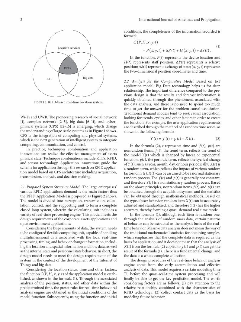
Real-time supervision
RTLSpositioningtechnology
ERP system
Position info
History info
Figure 4: Vehicles battery supervision using RTLS and ERP.
threshold setting from the use of location data meet thedesign requirements of the application model well.
3.3. Problems and Demands for Open Environment BatteryAsset Management. The battery storage management canrefer to similar data asset management scheme describedabove. The main difference in warehouse management isthe battery maintenance of large amounts of exchange data,roughly in the tens to hundreds of megabytes. The datatransmission is the major demand in storage place denselystacked. Only a small amount of data is returned to theoperator in the course, on account of the use of CAN and tripcomputer in conjunction with the mobile communicationnetwork, with the amount of data far less than the static dataexchange and collection frequency being limited.
3.4. Critical Designs for Open Environment Batteries AssetManagement Scheme. Battery storage management has dif-ferent demands from data asset management, focusing ondata delivery to the exclusion of networking, positioning, andcollaborative technology. It uses active RFID to complete theWi-Fi channel open and closed to achieve data transmission.Figure 4 shows vehicles battery supervision need the combi-nation of RTLS and ERP.
RFID is not only identification achieved but also anexcitation switch to realize the specified batteryWIFI channelestablished. In the actual process, tens to hundreds of batterymanagement communication can be accomplished only withseveral IP addresses. Using RFID as the management of theaddress and the communication channel solves the singlebattery status data exchange problem, which is a smallproportion of the cost for valuable equipment.
In the operating environment, the battery status infor-mation collected by the battery management system willbe transmitted to the remote by CAN, ECU and on-boardcomputer shown as Figure 5. Environmental status of thebattery in the car can be achieved using low-frequency com-munication. Associated together with cars, 𝑃(𝑡) is realized byGPS or GSM, and Δ𝑆(𝑡) is obtained by RFID sensor.
3.5. Summaries for Battery Assets Management Practice
(1) WIFI excitations realize detections of the battery inthe shelf.
(2) DTUmonitoring with GPRS dealing with the batterydata transmission.
(3) Battery status collected by BMS is transmitted by theCAN bus to the vehicle terminal.

International Journal of Antennas and Propagation 5
RFIDexcitation
Control signal
GatewayGateway
WIFI
U1
U1U2U3
Batteries tagsBatteries tags
Warehousingenvironment
Openenvironment
Low-frequency signal
Batterycompartment
ECU
CANCAN
In car
Onboardcomputer
GPRS
Remotemanagement
Figure 5: Design on RFID sensor application for battery assets.
4. Analysis for Application Practice
At present, the existing typical implementations include (1)passive UHF RFID application, using cabinet near fieldantenna design and installation location information, real-izing equipment inventory and real-time location, is thecase with patented product for data center; (2) active RFIDand rack infrared integrated application: the solution canbe viewed as the integrated application of active RFID andsensor technology. Real-time location-based applications ofthe microenvironment of the data center do not depend on asingle positioning technology advanced but select and definethe product by the actual needs.
(1) Passive RFIDDesign Defects.According to the comparisonbetween design and model, the relative positional 𝑃(𝑡) isprimarily obtained on the discrete-time 𝑇1, 𝑇2, and 𝑇3, andso forth. Since adjacent time difference is not the same, alongwith the lack of temporal association and relationship ofstate and behavior, the design does not fully comply with themodel. In addition, passive RFID location-based applicationsneed to deploy a large number of antenna and reader, and thenumber of antenna elements cannot be changed, although itis possible to reduce the reader number by port splitters.
(2) Active RFID Scheme Design Features. Based on the above,relative position Δ𝑃(𝑡) is additionally used with discrete-time changed into real-time and position increases precisely.Despite the timing relationship, the lack of the status andbehavioral variables do not fully comply with the model, butthe application has been relatively close.
According to application data characteristics of theelectric vehicles services platform, operation data can bedivided into basic data, information file data, processingdata, periodic data, documents data, and statistics querydata. Currently, big data with real-time sensor data is thenew application. The new practical experiment data wouldbe collected and presented to justify the practice of theseproposed models.
5. Advantage of Applications from the Model
The change in location, timing, and behavior is as theinformation input. The relative position and area position
from active RFID form the basis of the space-time cubegeospatial data. Staff position change improves the interac-tivity, using multidimensional and massive data modelingas the formation of real-time applications. The effectivenessand consistency is improved compared to traditional RFIDsystems. In practical applications, the selection of passiveRFID, active RFID, and RFID with sensors tends to the thirdwhich has obvious application value due to the fact that theprior two are the actual product, and the last is applied to theactual project.
5.1. Changes for IT Assets Management Application. Real-time positioning sensors can take into account dynamic,static, and cabinet-level position identification. The inte-grated innovation in application mode based on behavioralanalysis can be achieved. For example, classified usage rulesof tags created, the function in each tag dynamic changes.Classification model is established based on the usage fre-quency of the tags, and taking advantage of middlewarefor the classification management function in Figure 6, thedifferent units of tag can dynamic wake up and close. Thespecific design includes priority for critical equipment to useactive tags; combined with sensor, increasing the equipmentmotion recognition; the combination of video and active tagsto increase staff identification and behavior monitoring; real-time collaborativemanagement of the operation of the deviceand persons. In addition, the policy is applied mainly forthe classification of the cabinet-level identification. Just thecabinet level monitoring with simplified static positioningaccuracy and mobile positioning can record formation of𝐶(𝑃,𝐻, 𝑥, 𝑦, 𝑡) to form an effective monitoring.
5.2. Benefit of Vehicle Battery Application. The importanceof electric vehicle batteries is obvious, the potential valueof which is the life cycle management, and it is extremelyimportant for operator to obtain comprehensive data ascommercial design using RFID hardware infrastructure atdifferent stages. From the perspective of standard and indus-trial development, we still require the reliable design to meetelectric vehicles battery needs of production, leasing andoperations. However, for State Grid battery management, itis already an important attempt.

6 International Journal of Antennas and Propagation
Application software layer
Driv
er
Standard protocol stack(ARP, BOOTP, DHCP,
ICMP, IP, TCP,
Task monitorC runtime library RFID protocol
Fire wall
Label R and W Data transfer Device managementHTTP server
Configuration and upgrade
I2C
URAT
ETH
WDG
Flash
GPIO
Timer
Fault monitor
Hardware platform
EPROM
Hardware diagnostics
MAC program
Preemptive multitasking real time
operating system microkernelBoot loader
(dynamic IP access)
UDP, . . .)
Figure 6: Front-end software infrastructure of RFID applications.
Electric vehicle asset management and IT assets bothtake advantage of RFID technology to enhance the reliability,security, and trace ability of asset.Thedifference between datacenter application and batterymanagement is that the formeris applied to closed environment and the latter is applied incomplex open environment.
6. Conclusions
In the current social environment and development oppor-tunities, taking advantage of RFID and other technologies,as well as the practical demand-driven, the new applicationecological system is being formed; some of which are local forenterprisesmanagement and the others are open applicationsthat are beneficial to social services, to promote RFID con-tinuous development.
Conflict of Interests
The authors declare that there is no conflict of interestsregarding the publication of this paper.
References
[1] S. Milgram, “The small world problem,” Psychology Today, vol.2, no. 1, pp. 60–67, 1967.
[2] R. Cohen and S. Havlin, “Scale-free networks are ultrasmall,”Physical Review Letters, vol. 90, no. 5, Article ID 058701, 4 pages,2003.
[3] R. Albert, H. Jeong, andA. Barabasi, “Error and attack toleranceof complex networks,” Nature, vol. 406, no. 6794, pp. 378–382,2000.
[4] D. J. Watts and S. H. Strogatz, “Collective dynamics of “small-world” networks,”Nature, vol. 393, no. 6684, pp. 440–442, 1998.
[5] J. M. Kleinberg, “Navigation in a small world,”Nature, vol. 406,no. 6798, p. 845, 2000.
[6] A. J. G. Hey, The Fourth Paradigm: Data-Intensive ScientificDiscovery, 2009.
[7] D. Howe, M. Costanzo, P. Fey et al., “Big data: the future of bio-curation,” Nature, vol. 455, no. 7209, pp. 47–50, 2008.
[8] J. Dean and S.Ghemawat, “MapReduce: simplified data process-ing on large clusters,” Communications of the ACM, vol. 51, no.1, pp. 107–113, 2008.
[9] C. Anderson, “The end of theory: the data deluge makes thescientific method obsolete,” Wired, 2008.
[10] S. Ghemawat, H. Gobioff, and S. T. Leung, “The Google filesystem,” ACM SIGOPS Operating Systems Review, vol. 37, no. 5,pp. 29–43, 2003.
[11] L. Guojie and C. Xueqi, “Research status and scientific thinkingof big data,” Strategy and Policy Decision Research, vol. 6, pp.647–657, 2012.
[12] E. A. Lee, “Cyber physical systems: design challenges,” inProceedings of the 11th IEEE Symposium on Object-OrientedReal-Time Distributed Computing (ISORC ’08), pp. 363–369,Orlando, Fla, USA, May 2008.
[13] Y. Tan, M. C. Vuran, and S. Goddard, “Spatio-temporal eventmodel for cyber-physical systems,” in Proceedings of the 29thIEEE International Conference on Distributed Computing Sys-tems Workshops (ICDCSW ’09), pp. 44–50, 2009.
[14] J. E. Kim and D. Mosse, “Generic framework for design,modeling and simulation of cyber physical systems,” ACMSIGBED Review, vol. 5, no. 1, pp. 1–2, 2008.
[15] R. R. Rajkumar, I. Lee, L. Sha, and J. Stankovic, “Cyber-physicalsystems: the next computing revolution,” in Proceedings of the47th Design Automation Conference (DAC ’10), pp. 731–736,ACM, June 2010.
[16] H. Ahmadi, T. F. Abdelzaher, and I. Gupta, “Congestion controlfor spatio-temporal data in cyber-physical systems,” in Proceed-ings of the 1st ACM/IEEE International Conference on Cyber-Physical Systems (ICCPS ’10), pp. 89–98, ACM, April 2010.

International Journal of
AerospaceEngineeringHindawi Publishing Corporationhttp://www.hindawi.com Volume 2014
RoboticsJournal of
Hindawi Publishing Corporationhttp://www.hindawi.com Volume 2014
Hindawi Publishing Corporationhttp://www.hindawi.com Volume 2014
Active and Passive Electronic Components
Control Scienceand Engineering
Journal of
Hindawi Publishing Corporationhttp://www.hindawi.com Volume 2014
International Journal of
RotatingMachinery
Hindawi Publishing Corporationhttp://www.hindawi.com Volume 2014
Hindawi Publishing Corporation http://www.hindawi.com
Journal ofEngineeringVolume 2014
Submit your manuscripts athttp://www.hindawi.com
VLSI Design
Hindawi Publishing Corporationhttp://www.hindawi.com Volume 2014
Hindawi Publishing Corporationhttp://www.hindawi.com Volume 2014
Shock and Vibration
Hindawi Publishing Corporationhttp://www.hindawi.com Volume 2014
Civil EngineeringAdvances in
Acoustics and VibrationAdvances in
Hindawi Publishing Corporationhttp://www.hindawi.com Volume 2014
Hindawi Publishing Corporationhttp://www.hindawi.com Volume 2014
Electrical and Computer Engineering
Journal of
Advances inOptoElectronics
Hindawi Publishing Corporation http://www.hindawi.com
Volume 2014
The Scientific World JournalHindawi Publishing Corporation http://www.hindawi.com Volume 2014
SensorsJournal of
Hindawi Publishing Corporationhttp://www.hindawi.com Volume 2014
Modelling & Simulation in EngineeringHindawi Publishing Corporation http://www.hindawi.com Volume 2014
Hindawi Publishing Corporationhttp://www.hindawi.com Volume 2014
Chemical EngineeringInternational Journal of Antennas and
Propagation
International Journal of
Hindawi Publishing Corporationhttp://www.hindawi.com Volume 2014
Hindawi Publishing Corporationhttp://www.hindawi.com Volume 2014
Navigation and Observation
International Journal of
Hindawi Publishing Corporationhttp://www.hindawi.com Volume 2014
DistributedSensor Networks
International Journal of