Research Article Real-Time Human Motion Capture Driven by ...
15
Research Article Real-Time Human Motion Capture Driven by a Wireless Sensor Network Peng-zhan Chen, Jie Li, Man Luo, and Nian-hua Zhu College of Electrical and Electronic Engineering, East China Jiaotong University, Nanchang, Jiangxi 330013, China Correspondence should be addressed to Jie Li; [email protected] Received 9 July 2014; Revised 8 January 2015; Accepted 26 January 2015 Academic Editor: Alexander Pasko Copyright © 2015 Peng-zhan Chen et al. is is an open access article distributed under the Creative Commons Attribution License, which permits unrestricted use, distribution, and reproduction in any medium, provided the original work is properly cited. e motion of a real object model is reconstructed through measurements of the position, direction, and angle of moving objects in 3D space in a process called “motion capture.” With the development of inertial sensing technology, motion capture systems that are based on inertial sensing have become a research hot spot. However, the solution of motion attitude remains a challenge that restricts the rapid development of motion capture systems. In this study, a human motion capture system based on inertial sensors is developed, and the real-time movement of a human model controlled by real people’s movement is achieved. According to the features of the system of human motion capture and reappearance, a hierarchical modeling approach based on a 3D human body model is proposed. e method collects articular movement data on the basis of rigid body dynamics through a miniature sensor network, controls the human skeleton model, and reproduces human posture according to the features of human articular movement. Finally, the feasibility of the system is validated by testing of system properties via capture of continuous dynamic movement. Experiment results show that the scheme utilizes a real-time sensor network-driven human skeleton model to achieve the accurate reproduction of human motion state. e system also has good application value. 1. Introduction With the development of computer science, 3D display tech- nology has become increasingly mature; human motion reconstruction technology has broad application prospects in areas such as game, film and television design [1, 2], medical science [3, 4], and sports training [5, 6]. In the field of game design, many major sports games, such as “3Dbasketball” and “NBA,” have combined human motion capture with virtual reality technology, so objects have become truly vivid and lifelike. In the film industry, many films, such as “Avatar” and “e Adventures of Tintin,” predominantly use human motion capture and virtual reality technology. In the field of medical science, the technology is also widely used in orthopedics, surgeries, physical therapy, and other areas to help doctors fully understand patients’ condition through a comparison of the motion attitude of patients before and aſter rehabilitation. In the field of sports training field, real- time monitoring of athletes’ training state is achieved through the display of a real-time tracking interface in athletes who wear motion capture equipment, such as wearable sensor vests [7]. At present, the common motion capture systems are based on either optical or inertial sensors. In general, optical systems are used for large game production, film shooting, and other applications that require high accuracy. However, they have high demands on the environment and are also expensive. Because of their relatively short history, motion capture systems that are based on inertial sensors have yet to be fully developed. Given their low cost and close connection with the development of information technology features, however, such systems have become a new research field in human–machine interaction. Motion capture, as the name implies, is “the reconstruc- tion and simulation of the test object’s motion behavior.” In scientific jargon, the model can be repeated to test the move- ment of an object through acquisition of the motion data of the test object and mapping of these data onto the motion Hindawi Publishing Corporation International Journal of Computer Games Technology Volume 2015, Article ID 695874, 14 pages http://dx.doi.org/10.1155/2015/695874
Transcript of Research Article Real-Time Human Motion Capture Driven by ...

Research ArticleReal-Time Human Motion Capture Driven bya Wireless Sensor Network
Peng-zhan Chen Jie Li Man Luo and Nian-hua Zhu
College of Electrical and Electronic Engineering East China Jiaotong University Nanchang Jiangxi 330013 China
Correspondence should be addressed to Jie Li 1165530693qqcom
Received 9 July 2014 Revised 8 January 2015 Accepted 26 January 2015
Academic Editor Alexander Pasko
Copyright copy 2015 Peng-zhan Chen et al This is an open access article distributed under the Creative Commons AttributionLicense which permits unrestricted use distribution and reproduction in any medium provided the original work is properlycited
The motion of a real object model is reconstructed through measurements of the position direction and angle of moving objectsin 3D space in a process called ldquomotion capturerdquo With the development of inertial sensing technology motion capture systemsthat are based on inertial sensing have become a research hot spot However the solution of motion attitude remains a challengethat restricts the rapid development of motion capture systems In this study a human motion capture system based on inertialsensors is developed and the real-time movement of a human model controlled by real peoplersquos movement is achieved Accordingto the features of the system of human motion capture and reappearance a hierarchical modeling approach based on a 3D humanbody model is proposed The method collects articular movement data on the basis of rigid body dynamics through a miniaturesensor network controls the human skeleton model and reproduces human posture according to the features of human articularmovement Finally the feasibility of the system is validated by testing of system properties via capture of continuous dynamicmovement Experiment results show that the scheme utilizes a real-time sensor network-driven human skeleton model to achievethe accurate reproduction of human motion state The system also has good application value
1 Introduction
With the development of computer science 3D display tech-nology has become increasingly mature human motionreconstruction technology has broad application prospects inareas such as game film and television design [1 2] medicalscience [3 4] and sports training [5 6] In the field of gamedesignmanymajor sports games such as ldquo3Dbasketballrdquo andldquoNBArdquo have combined human motion capture with virtualreality technology so objects have become truly vivid andlifelike In the film industry many films such as ldquoAvatarrdquoand ldquoThe Adventures of Tintinrdquo predominantly use humanmotion capture and virtual reality technology In the fieldof medical science the technology is also widely used inorthopedics surgeries physical therapy and other areas tohelp doctors fully understand patientsrsquo condition through acomparison of the motion attitude of patients before andafter rehabilitation In the field of sports training field real-timemonitoring of athletesrsquo training state is achieved through
the display of a real-time tracking interface in athletes whowear motion capture equipment such as wearable sensorvests [7]
At present the common motion capture systems arebased on either optical or inertial sensors In general opticalsystems are used for large game production film shootingand other applications that require high accuracy Howeverthey have high demands on the environment and are alsoexpensive Because of their relatively short history motioncapture systems that are based on inertial sensors have yet tobe fully developed Given their low cost and close connectionwith the development of information technology featureshowever such systems have become a new research field inhumanndashmachine interaction
Motion capture as the name implies is ldquothe reconstruc-tion and simulation of the test objectrsquos motion behaviorrdquo Inscientific jargon the model can be repeated to test the move-ment of an object through acquisition of the motion data ofthe test object and mapping of these data onto the motion
Hindawi Publishing CorporationInternational Journal of Computer Games TechnologyVolume 2015 Article ID 695874 14 pageshttpdxdoiorg1011552015695874
2 International Journal of Computer Games Technology
capture focuses on the interaction process between humansand computers How to interact the use of any mediumhow to facilitate object interaction building the interactivetime and other issues are important to consider becausethese issues determine the merits of the system A numberof challenges were confronted by scholars who focused oninteractive algorithms and real-time system performanceExceptions are world-renowned companies such as ldquo3dSuitrdquoand ldquoXsensrdquo which have developed excellent-performingmotion capture systems Based on trade secrets and otherissues however the core of the algorithm remains a majorissue that affects not only the accuracy of the motion capturesystem but also its real-time properties Basing on existingalgorithms this study analyzes in depth the data capturedby sensors and establishes a data-driven algorithm modelfrom sensors to human models We successfully facilitatethe interaction between human and model The real-timeproperties of the system are also considerably improvedcompared with those of the traditional system
The selection model is also closely linked with the meritsof the system The performance of different models mayalso be different At present the human body model ismainly categorized into the rod model solid model surfacemodel and multi-level model [8] The rod model selects alimited rigid segment linking with a joint that lacks fidelitythe solid model simulates the structure of the human bodythrough simple solid graphics that requires a large amountof calculation and has poor stability the multi-level modelincludes the skeleton muscle and skin layers that have highcomplexity and require more computation and the surfacemodel is composed of skeleton and skin layers that are easyto realize and require a small amount of calculation [9] In thisstudy we propose a method based on surface model theoryto construct a 3D human skeleton model
The process and results of the experiment are described inthis study In Section 2 starting from rigid body dynamicswe analyze the structure and design the hardware systemIn Section 3 the human motion data based on the poly-merization mechanism is analyzed and the attitude of thereconstruction process is described according to the algo-rithm In Section 4 the experimental results are presentedand theoretical verification is conducted In Section 5 theexperiment is discussed further
2 Related Work
Motion capture has a relatively long history as reflected inthe old Chinese saying ldquoSet up a pole and see its shadowrdquo themeaning of this sentence is to judge themovement of the polebased on the shadow through solar light irradiation in factthe process is a way to capture the attitude of an object butsuch a process still considerably depends on the original lightimaging With advancements in science and motion capturetechnology the development from original light imaging toan optical and inertial sensing level-based system representsa major leap forward Optical motion capture usually obtainsthe trajectory of human motion data through high-speedcameras that shoot continuous image sequences of the human
body the target unit is required to be equipped with therelevant features of the spot to complete the monitoring andtracking processes A previous study [10] described opticalmotion capture in detail Inertial motion capture involveshuman motion capture data obtained from the subject whowears limb sensor nodes on the target unit As a result themotionmodel achievesmotion reconstruction In the presentstudy we focus on the problem of inertial motion capture
21 Attitude Algorithm In a motion capture system based oninertial sensing the human body structure can be simplifiedto a number of rigid bodies connected by a hinge joint thatconsists of a more rigid body structure through real-timeestimates of each rigid body postureThe real-timemovementof the human body is then described so parts of the bodypose estimation serve as the basis of motion capture based oninertial sensing
Attitude estimation of the human limb is primarilyachieved by placement of the sensor in the surface of therigid body Miniature inertial sensors are found in a three-axis accelerometer three-axis gyroscope and three-axismag-netometer that can be considered as gravity vector understatic or low speed three-axis accelerometer can be used asan inclinometer to determine the relative direction of thehorizontal plane The magnetometer measures the magneticfield vector under the sensor coordinate systems and theprinciple followed is similar to that of a compass which canbe used to determine the rotation around the vertical axisThe gyroscope is used to measure angular velocity and theangle can be obtained through the angular velocity integralAcceleration and the magnetic field are complementary tothe angular velocity so the data of accelerometer and mag-netometer can be used to eliminate the drift by integration ofthe angular velocity
However the acceleration and themagnetic field strengthmay be disturbed in different situations When accelerome-ters measure motion acceleration and gravitational acceler-ation motion acceleration is negligible in high-speed situ-ations Ferromagnetic materials or electronic products candisturb the surrounding magnetic field and form magneticvector bias These two issues have a major effect on attitudeestimation
Many domestic and foreign scholars have proposeddifferent methods to address these problems For instanceLuinge et al [11] drifted the angle to the horizontal onlyby using microgyroscopes and accelerometers but did noteliminate the rotational drift on the vertical direction Foxlin[12] described two navigation systems based on inertial andmagnetic sensors that were used for commercial purposeRoetenberg et al [13 14] proposed a compensation Kalmanfilter algorithm in which he integrated a compensationmodel on the basis of the error model to offset the effectof changes in the magnetic field to the attitude estimationHowever the algorithm model calculation was complicatedand high-speed movement acceleration interference was notconsidered Bachmann [15] proposed a Kalman filter algo-rithm based on quaternion and he estimated the directionby using the low-frequency part of acceleration andmagnetic
International Journal of Computer Games Technology 3
field intensity he also measured attitude with the angularvelocity at high speed Yun and Bachmann [16] used theQUEST algorithm to obtain a quaternion and thus estimatethe attitude with acceleration and magnetic field vectorsFurther integration with the angular velocity was conductedand a linearized observation equation was used howevera higher complexity than that of the QUEST algorithmwas achieved Later Yun et al used the factor quaternionalgorithm (FQA) [17] to replace QUEST and as a resultthe computational complexity of the algorithm was reducedHowever the removal of the QUEST algorithm still did notaddress the problem on the magnetic field and the interfer-ence of acceleration
We attempted to reduce the impact of the magneticfield and the acceleration of attitude on the basis of variouspostures in the reference fusion algorithm
22 Motion Model Construction Method In human motioncapture techniques the human body model is a graphicaldescription for the human form by abstraction of the humanbody to simulate or reproduce the action of the humanmodelwith this approach the purpose of this study can be achievedwith the use of human motion tracking data acquired fromthe device The goal of the inertial sensing motion capturesystem is to utilize motion sensors for the collection of dataon the human body in order to drive the established humanmodel and thus achieve an approximate simulation of humanmotion The establishment of a human motion model that isin line with the characteristics of human behavior is thereforeimportant for the vivid simulation of human action
According to the data collection methods and the direc-tion of motion analysis the construction methods of thehuman model in the human motion capture system areusually different Generally however the human motionmodel can be classified as 2D or 3D based on different spatialproperties
A 2D human model refers to the calibration of humanmotion and a description of the movement of the limbs Thismodel can be further classified into the 2D sticks and 2Dregional models
The 2D sticks model uses geometry to represent theskeletal structure of the body For example a straight linecan be used to represent bones whereas points representjoints Karaulova et al [18] developed a stratified humanskeleton model with straight lines and points in a humanbodymotion tracking systemon the basis ofmonocular videosequences The highly simplified description of the humanbody in the model makes it suitable for video-based motioncapture sequences However the lack of representation of thehuman form makes the model lose its verisimilitude
The 2D regional model refers to the use of a 2D regionto represent a certain part of the body in the analysis ofmotion capture based on image sequence Leung and Yang[19] used the strip area to represent a part of the humanbody in constructing a human body model in a human bodycontour marking system The 2D regional model generallyapplies to the extraction of the characteristics of a region in
terms of human motion in graphic sequence However thismethod causes considerable information loss in the processof image processing
3D human body model calibration refers to the humanbody limbs in human motion in 3D space and to the descrip-tion of gestures The model can generally be categorized intothe 3D geometric model and the 3D mesh model
The 3D geometry representation method refers to the useof some basic geometric figures to complete the constructionof the human body model in 3D space Wachter and Nagel[20] established a 3Dhumanbodymodel by using an ellipticalcone in human motion capture based on monocular videosequences Remondino and Roditakis [21] used lines andpoints to represent human body bone joints and the humanskeletal system respectively as well as the ellipse to representthe 3D human body model in a single image or in monocularvideo sequence human motion reconstruction
The 3D mesh model is defined according to the surfacecharacteristics of the human body It builds on the model ofthe human body through many facets and grids Using thismethod to establish a model of the human body results ina lifelike outcome because the method can vividly describeouter human characteristics Sminchisescu [22] proposeda construction method by using an elliptic grid for thehuman bodymodel to establish a humanmodel and facilitatemotion reconstruction based onmonocular video sequencesTheobalt et al [23] designed a human-level model repre-sented by triangular meshes to strengthen the outline ofhuman motion capture The goal of the inertial sensingmotion capture system is to capture the attitude of each limbthrough inertial sensors and use the motion data to drive thehuman model to achieve motion tracking Establishing a 3Dmodel of the human body is therefore necessary
Although the 3D mesh model can vividly describe thecontour features of the muscle and skin the muscle defor-mation will occur when the body is in motion and this phe-nomenon increases the difficulty of graphic reconstructionTo address this situation this study constructs a 3D humanskeleton model that completely matches the human bodybiomechanical characteristics of the human body modelWe also use kinematics theory to restrain and limit thedevelopment of the skeletal model and thus achieve accuratelimb posture features during human movement
3 Attitude Calculations
In this section we describe the solution to the attitude ofhuman motion through sensors Initially we select the typesof sensors and consider the means of communicationbetween hardware Then we calculate the attitude of a singlenode by combining sensor data Finally we calculate theattitude from a single node to the entire body according tothe movement mechanism of the human skeleton
31 Data Collection and Communication Network The iner-tial sensor-based human motion capture system examinedin this study contains an attitude acquisition module aninformation processing module and an attitude reconstruc-tion module The attitude acquisition module combines
4 International Journal of Computer Games Technology
Figure 1 mpu-9150 sensor
Figure 2 nrf-51822 module
the mpu-9150 (integrated accelerometer gyroscope andmagnetometer) microsensor with nrf-51822 (BLE 40 ultra-low-power module) mpu-9150 and nrf-51822 as can be seenin Figures 1 and 2 The module forms a small sensor networkbetween each node We also set two sink nodes to receivethe transmission data from the subnode The sensor networkconfiguration is shown in Figure 3 To communicate with thehost computer terminal we use Bluetooth technology thetransmission distance is about 10 meters
32 Single Node Attitude Solution In the process of humanmotion each joint wears a sensor node and the attitudecalculation algorithm of each node consists of the followingsteps
Step 1 (sensor calibration) For the gyroscope the main workis to remove zero offset which is to calculate the zero biasthrough many timesrsquo weighted average and make the initialvalue minus zero offset For the accelerometer at first weset low-pass filter to eliminate jitter effects and then usingthe weighted average filter to eliminate jitter effect furtherThe calibration of the magnetometer involves two aspectshard offset and soft offset Hard offset is mainly caused bythe hardmagneticmaterials It shows that the scatter diagramof random rotation magnetometer readings is a sphericalshell away from the origin The center of the spherical shellis the vector value of the hard offset In this system weobtain the hard offset through a large number of samplingsand calculation of the minimum residual value Soft offset ismainly caused by soft magnetic materials It shows that thescatter diagram of random rotation magnetometer readings
NRF-51822
Bluetoothmodule
NRF-51822
IIC
Bus
MPU-9150
NRF-51822
IICMPU-9150
NRF-51822
IICMPU-9150
middot middot middot
Figure 3 Configuration of the sensor network
is an ellipsoidal shell centered at the origin The value of thesoft offset can be represented in a matrix through matrixsolution the soft offset can be calculated The calibration ofthe magnetometer is therefore achieved To reduce the noise-induced jitter a low-pass filter must be set to filter the data ofthe accelerometer and magnetometers
Step 2 (the angular velocity integral) We measure angularvelocity information in the process of human motion byusing a gyroscope With integral operation on the angularvelocity the angle component in the process of motion canbe obtained Using a first-order high-pass filter followed by afirst-order Taylor expansion method we finally obtain initialquaternion information of the human body in the process ofmovement
Step 3 (solution attitude of the accelerometer and magne-tometer) We use FQA algorithm to transform the accel-eration value and the magnetic field information into theattitude value The advantages are as follows First themagnetometer data have an effect on the heading angle only(Yaw) Second using the algorithm significantly reduces theeffect of the magnetic field on the attitude computationThird the amount of calculation is considerably reducedTheFAQ is also limited but the use of an ideal environmentmeans no linear acceleration exists and if it does it is onlyunder the effect of the magnetic field This condition meansthat the FAQ results in little disturbance in linear accelerationand magnetic field interference
We conducted a verification experiment We placed theinertial sensor model in static state and observed the attitudecalculated by the FAQ algorithm Then we repeat making aferromagnetic material away and close to the sensor moduleand continue to observe the changes in the moment wave-form Figure 4(a) presents the attitude angle calculated bythe FAQ algorithm when little magnetic interference existsFigure 4(b) presents the attitude angle calculated by the FAQalgorithm when large magnetic interference exists From thechart we can see that in the case of nonlinear acceleration theroll angle and the pitch angle calculated by the FAQalgorithmhave no distortion with or without magnetic interferenceMagnetic interference only has an effect on the Yaw angle
Step 4 (sensor data fusion) We fuse the data of the sensors Insummary in the case of linear acceleration or a largemagneticfield only the attitude information obtained through theangular velocity integral works With the uniqueness of
International Journal of Computer Games Technology 5
0 500 1000 1500 2000
0
05
1
Number of samples
Attit
ude a
ngle
(deg
)
YawPitchRoll
minus1
minus05
(a)
0 500 1000 1500 2000
0
50
Number of samples
Attit
ude a
ngle
(deg
)
minus150
minus100
minus50
YawPitchRoll
(b)
Figure 4 (a) Attitude calculated by the FAQ algorithm when little magnetic interference exists in the stationary state (b) Attitude calculatedby the FAQ algorithm when large magnetic interference exists in the stationary state
Accelerometersensor
Magnetometersensor
Gyrosensor
Low-passfilter
FAQalgorithm
Angular velocityintegral
FinalgestureΣ
Figure 5 Attitude calculation of the signal node
the representation of the direction cosine matrix consideredthe opposite case sets the weight and average value for theattitude value obtained from the two preceding methods Inslow motion the two move cooperatively during strenuousexercise only the angular velocity integral works
The above process can be summarized as a complemen-tary filter The single node attitude solution process is shownin Figure 5 By using the attitude calculation of a single nodewith the above algorithm we can obtain the attitude dataof each node In the actual process we commonly use therotationmatrix to represent the rotation of a 3D object Manymethods can be used to express the rotationmatrixThemostcommon ones are the Euler angle and quaternion Howeverthe Euler angle involves the gimbals problem so we use thequaternion to represent the rotation matrix in the actualprocess To understand the process of the experiment weconverted the quaternion to the Euler angleThen we choosethe palm as the wearing node and observe the effect of thecurve motion
(a) We place the palm on the level direction this isstep 1 After a smooth palm repeats the movementvertically bends down to a certain angle and returnsto the horizontal state this process is considered asstep 2 After step 2 the palm is bent vertically up to acertain angle and then is returned to the horizontalposition this is step 3 The movement process isshown in Figure 6(a) and the attitude motion curveis shown in Figure 6(b)
(b) We place the palm to be stable on the level directionthis is step 1 The palm is rotated right to a certainangle along the arm axis and then is returned to thehorizontal position this process is considered as step2 After step 2 the palm is rotated left to a certainangle along the arm axis and then is returned tothe horizontal position this is step 3 The movementprocess is shown in Figure 7(a) and the attitudemotion curve is shown in Figure 7(b)
(c) We place the palm on the level direction this is step 1The palm is bent right to a certain angle along the armaxis and then is returned to the horizontal positionthis process is considered as step 2 After step 2 thepalm is bent left to a certain angle along the arm axisand then is returned to the horizontal position this isstep 3Themovement process is shown in Figure 8(a)and the attitudemotion curve is shown in Figure 8(b)
With the motion curve the designed algorithm of theexperiment solves the interference problem of the magneticfield and the acceleration in the attitude computation Theattitude calculation accuracy can meet the requirements
6 International Journal of Computer Games Technology
Step 1 Step 2 Step 3
(a)
0 200 400 600 800 1000 1200minus100
minus50
0
50
Number of samples
Attit
ude a
ngle
(deg
)
YawPitchRoll
Step 2
Step 1
Step 3
(b)
Figure 6 (a) The movement process (b) The attitude curve when the palm is bent vertically down and up
Step 1 Step 2 Step 3
(a)
0 200 400 600 800 1000minus60
minus40
minus20
0
20
40
Number of samples
Attit
ude a
ngle
(deg
)
YawPitchRoll
Step 3
Step 2
Step 1
(b)
Figure 7 (a) The movement process (b) The attitude curve when the palm is rotated left and right along the arm axis
33 The Body Attitude Solution The cooperative motion ofvarious body limbs is involved in the process of humanmotion tracking Analysis of the human body kinematicsprinciple indicates that the motion between various nodesinvolves related links Therefore calculating the attitude ofthe entire body is necessary
331 Posture Initialization Calibration In the process ofusing sensor nodes to capture human motion three coor-dinate transformations are involved inertial sensor coordi-nates geomagnetic coordinates and human skeleton coordi-nates The inertial sensor coordinate is set as the calibrated
coordinate system for the chip itself The establishment ofgeomagnetic coordinates is due to the fact that the data oneach axle of the magnetometer determine the magnetic fielddistribution detected by each axis However according to thedistribution of the magnetic field of earth the world coordi-nate system can be defined as the geomagnetic coordinates(the origin is the center of the earth the 119883-axis is alongthe equatorial plane pointing outward the 119884-axis is alongthe equatorial plane with a right orientation and the 119885-axispoints to the north) The human skeleton coordinates will bedefined in the following article During the experiment wemust initialize the pose calibration every time in the testingprocess that is calibrate the motion of the joint body of
International Journal of Computer Games Technology 7
Step 1 Step 2 Step 3
(a)
0 200 400 600 800 1000 1200minus60
minus40
minus20
0
20
Number of samples
Attit
ude a
ngle
(deg
)
YawPitchRoll
Step 1
Step 2
Step 3
(b)
Figure 8 (a) The movement process (b) The attitude curve when the palm is bent left and right along the arm axis
X-axisY-axisZ-axis
Figure 9 Lower limb structure diagram
the experimental individual and obtain the rotation matrixof any part of the human skeletal coordinate system fromthe sensor coordinates of this bone because of the differencebetween the wearing position and the individual We takethe limb system as an example According to the sensornode programming the lower limb needs three sensor nodeswhich are foot 119869 leg 119870 and thigh 119871 respectively to conductthe initialization calibration Figure 9 shows the lower limbstructure diagram The calibration process is as follows
(1) Lower limb toward the lateral stretch with the staticaction at this time the acceleration of gravities 119892119869 and 119892119896 can
be obtained from a lower leg sensor node and foot node andthen the rotationmatrix119884119869 of 119902
119887
119869of the leg and119884119870 of 119902
119887
119870of the
foot can be calibrated
119884119869 = minus11989211986910038161003816100381610038161198921198691003816100381610038161003816
119884119870 = minus11989211987010038161003816100381610038161198921198701003816100381610038161003816
(1)
On the basis of step 1 turn the lower limbs forward about90∘ from rear of your body then turn about 90∘ backwardfrom front of your body From the dynamic posture in thelower limb movement process we can obtain the outputangular velocity readings 120596119872
119869and 120596119872
119870and the reverse read-
ings 120596119873119869and 120596119873
119870 which correspond to the thigh leg and foot
sensor nodes Therefore the rotation matrix 119883119869 of 119902119869 of thefoot and119883119870 of 119902119870 of the leg can be calibrated as follows
119883119869 = minus
120596119873
119869
10038161003816100381610038161003816120596119873119869
10038161003816100381610038161003816
=
120596119872
119869
10038161003816100381610038161003816120596119872119869
10038161003816100381610038161003816
119883119870 = minus120596119873
1198701003816100381610038161003816120596119873119870
1003816100381610038161003816
=120596119872
1198701003816100381610038161003816120596119872119870
1003816100381610038161003816
(2)
The rotation matrix for the foot and the leg can be furtherobtained as follows
119902119887
119869= (119883119869 119883119869 times (119884119869 times 119883119869) 119884119869 times 119883119869)
119902119887
119870= (119883119870 119883119870 times (119884119870 times 119883119870) 119884119870 times 119883119870)
(3)
(2) The lower limbs shall be upright initially then extendthem right ahead about 90∘ with feet being perpendicularto the horizontal plane We then obtain the thigh angular
8 International Journal of Computer Games Technology
velocity 120596119871 so the thigh rotation matrix 119884119871 of 119902119871 can becalibrated as follows
119884119871 =12059611987110038161003816100381610038161205961198711003816100381610038161003816
(4)
(3) The lower limbs shall be upright initially then liftthe lower limbs backward at a constant speed until they arenearly perpendicular to the trunk that is return to the statein Step (1) According to this position we can obtain theacceleration of gravity119892119879
119871in the thighwhen it is in the upright
position When the leg is raised to the front we can obtainthe acceleration of gravity 119892119880
119871in the thigh at the moment
which in turn obtains the thigh rotation matrix 119885119871 of 119902119887
119871at
the moment
119885119871 = minus119892119879
119871times 119892119880
1198711003816100381610038161003816119892119879119871times 119892119880119871
1003816100381610038161003816
(5)
At the same time we obtain the rotation matrix 119902119887119871
119902119887
119871= (119885119871 times 119884119871 119884119871 119884119871 times (119885119871 times 119884119871)) (6)
332 Real-Time Calibration Attitude in the Human MotionProcess To obtain an accurate position of the human skele-tonmodel with the use of inertial sensors to measure the dataof human motion we need to calibrate the relative positionbetween the attitude measurement unit and the human bodymovement between moving limbs The calibration processaims to determine the rotation matrix between the inertialsensor coordinate system and the measured body coordinatesystem and between two movements of the limbs Fromthe perspective of rigid body dynamics the two connectedsegment bones are considered a rigid structure For examplethe No-119898 minus 1 and No-119898 bones are connected and then theattitude solution is determined The rigid structure of theconnected skeleton is shown in Figure 10
Suppose 119902119898minus1 is the rotation matrix of the sensor coor-dinate system that corresponds to the119898minus 1 bones comparedwith the geomagnetic coordinates 119902119887
119898minus1is the rotationmatrix
of the 119898 minus 1 bones with respect to their layout of the sensorcoordinate system 119902119886
119898minus1can be calculated through the initial
data measured by the sensor and 119902119887119898minus1
can be obtained inthe initialization calibration process which can calculate theattitude matrix 119902119898minus1 of the bone in its coordinates
119902119898minus1 = 119902119886
119898minus1otimes 119902119887
119898minus1 (7)
The rotation matrix 119902119898119898minus1
from bone119898 minus 1 to bone119898 is
119902119898
119898minus1= 119902119898minus1 otimes 119902119898 (8)
From formula (7) and (8) we can obtain
119902119898
119898minus1= 119902119886
119898minus1otimes 119902119887
119898minus1otimes 119902119886
119898otimes 119902119887
119898 (9)
Suppose119876119898119898minus1
is the transformationmatrix fromNo-119898minus1bone to No-119898 bone of the rigid body From the coordinatenature of the conversion matrix we can obtain the following
119876119898
119898minus1= [
119902119898
119898minus1119879119898
119898minus1
0 1] (10)
No-m bone
X-axisY-axisZ-axis
No-m minus 1 bone
Figure 10 Rigid structure of the connected skeleton
where 119879119898119898minus1
is the translation matrix from No-119898 minus 1 boneto No-119898 bone and each element of 119879119898
119898minus1is the true 3D data
of the No-119898 bone In this study the translation vector fromthe sensor coordinate system to the body coordinate systemas well as the coordinate translational component from thegeomagnetic to the sensor node coordinate is the upwardcomponent obtained from the acceleration value integration
The transformation matrix multiplication process pro-posed by Craig [24] indicates that the transformation matrixin the No-119898 bone corresponding to the first bone that can becalculated
119876119898
1= 119876119898
119898minus1119876119898minus1
119898minus2119876119898minus2
119898minus3sdot sdot sdot 1198763
21198762
1 (11)
According to the position of the first sensor node thetransformation matrix of the No-119898 bone can be calculatedIn the experiment however we can measure and calculatethe spatial coordinates119883119894 119884119894 and 119885119894 of the pelvic area in themodel
119883119894119884119894119885119894 =
3
sum
119894=1
119886119903
119894 (12)
where 119886119903119894denotes the vector in 119894 body and 119886119894 is the correspond-
ing limb length the recurrence relations are as follows
119886119903
1= (1198762
1)minus1
otimes 1198861 otimes 1198762
1
119886119903
2= (1198763
2otimes 1198762
1)minus1
otimes 1198862 otimes (1198763
2otimes 1198762
1)
119886119903
3= (1198764
3otimes 1198763
2otimes 1198762
1)minus1
otimes 1198863 otimes (1198764
3otimes 1198763
2otimes 1198762
1)
(13)
The vector of each limb can be obtained by orderrecursion Therefore the attitude and coordinate of theNo-119894 bone can be computed according to the root nodecoordinates virtual human motion reappearance can finallybe implemented
International Journal of Computer Games Technology 9
Head
Pelvis
Spine
ChestRight upper arm
Right fore arm
Right hand
Left upper arm
Left upper arm
Left hand
Right thigh Left thigh
Right calf Left calf
Right foot Left foot
(a)
X axisY axisZ axis
(b)
Figure 11 (a) Tree structure of the human hierarchy (b) Coordinate system of the human skeleton
We can obtain the vector of each limb followed byrecursion Therefore the attitude and coordinate of the No-119894bone can be calculated according to the coordinate of the rootnode Finally reproducing the motion attitude of the virtualhuman is realized
4 Model Construction
The human body is a complex life system and its exercisesystem consists of more than 200 bones more than 600muscles and countless nerves commanding these bones andmuscles in this regard specifying each piece of bone inthe experiment is impossible [25 26] Basing on the idea ofthe surface model and in view of the human body posturedata collected with the microsensor we propose a method toconstruct a 3D human skeleton model
41 Hierarchical Human Body Model Based on ConstraintsIn the literature [27] the automatic estimation of the hier-archical topological structure human skeleton model wasdescribed a detailed induction to the motion of the skeletonon the basis of the biomechanics principle was performed Inthe present study we took the topological structure of themodel and divided the human body into 16 bones and 14joints Bone segments are connected by jointsWe defined therelationship between the joints as the relationship betweenparent and son Parent node movement will lead to relevantsubnode movement In the definition of the hierarchicalstructure in the human body the pelvic node is the centerof gravity of the human body and is also the reference nodeof the entire body The pelvic node extends upward anddownward and traverses the entire skeleton The skeleton
Table 1 Description of human body joints
Nameof joint Parent bone Type of
joint FreedomLimitationof activity(degree)
Spinal None 0ndash50
Cervical Thoracicbones
Universaljoint 2 0ndash70
Shoulder Thoracicbones
Universaljoint 2 0ndash180
Elbow The upper armbones Hinge 1 0ndash145
Wrist Forearm bones Hinge 1 0ndash80
Hip Hip bones Universaljoint 2 0ndash180
Knee Thigh bones Hinge 1 0ndash140Ankle Leg bones Hinge 1 0ndash45
hierarchical structure is shown in Figure 11(a) Each joint ofthe human body presents angle constraints so Baerlocher[28] presented a clear definition the joints in different bonesof the body are categorized as rotary hinge and universaljoints Rotary joints have only one direction of freedom andtheir rotation range is limited to a certain extent Hinge jointshave one degree of freedom and they can twist and varicosearound other joints Universal joints have two degrees offreedom and they have a structure similar to that of a ballgroove They can move around the ball groove structureTable 1 shows the types and scope of activities of human bodyjoints
10 International Journal of Computer Games Technology
Figure 12 3D human body motion tracking system
Figure 13 Video sequence and 3D tracking performance
42The Coordinate System of the Human Skeleton This studypresents a coordinate system of the human skeleton based onjoint tree structure through analysis of the human skeletalhierarchy and the principle of 3D animation structure Thepelvic joints are taken as the reference points and thecoordinate system of other skeleton is calibrated accordingto the forward kinematics principle The skeletal coordinatesystem after calibration is shown in Figure 11(b)
43 The 3D Models of Motion Capture Based on the aboverelationship we designed a skeletal motion model consistentwith human motion by loading a human skeleton file basedonMicrosoft Visual Studio2012 platform andOpenGL devel-opment library environment Furthermore we can adjust theskeleton size and save the motion data of each bone Finallywe designed the terrain so that the effect is realistic Figure 12describes the 3D human skeletal motion tracking system
5 Results and Discussion
To validate the 3D human model that simulates real humanmotion we compared the key frame curve extracted from thereal human motion video image [29] with a gesture curvewhen the skeleton simulates relative movement
In the experiment we took the up limb system as anexample and shot the video sequence of continuous move-ment in the process of bending of human arms Throughimage processing we extracted the key frames curve of theelbow bending angle during the arm bending process andcompared it with the elbow bend angle data curve of the realhuman body simulating the corresponding action Accordingto their fitting degree we can judge the accuracy of themodel
We designed an arm motion tracking verification plat-form based on the algorithm described in this study In thecourse of the experiment we dressed the sensor node inthe elbow and tracked the real-time motion of the elbow
International Journal of Computer Games Technology 11
0 10 20 30 40
0
20
40
60
80
100
Time (s)
Bend
ing
angl
e (de
g)
The upper limb modelSequence of video frames
minus20
Figure 14 Bending angle curve of the upper limbs
(a)
(b)
Figure 15 (a) Right hand movement of a real human body (b) Tracking effect of right hand motion
The image sequence is based on the plane so we tracked thebending angle of the arm in the direction of the vertical planeand recorded the motion process with a high-speed videocamera By contrast in the visual motion video images and3Dmotion effects we can evaluate themotion tracking effectBy extracting the blending angle through the arm flexionextension in the video sequence and by comparing the outputangle of the sensors we can evaluate the effect of the system
according to the data point Figure 13 shows the comparisonof the effect of motion tracking and the video image andFigure 14 shows the comparison of the extracted output fromthe sequence of video frames and the actual output angle ofthe sensors
Figure 14 depicts the fact that two curve fittings canbasically meet the requirements the angle error is less than1 degree Therefore the model has some reference value
12 International Journal of Computer Games Technology
Figure 16 Tracking effect when the human body does waving movement
To evaluate the performance of the entire system actualhuman testing was performedWe tested themotion trackingeffect vis-a-vis the real motion of the human body byplacement of sensor nodes on all specified parts of the humanbody We took a photo on the effect of motion tracking in theexperiment with a high-speed camera and conducted somereal-time motion capture
(1) With the arm motion process taken as an examplewhen the system has stabilized after wearing duringthe experiment the right arm does the movementas shown in Figure 15(a) The system can accuratelytrack the motion trajectories of the arm Figure 15(b)shows the system dynamic trajectory tracking of thearm
(2) In the preceding process the motion capture of asingle arm is described However we need multiplemotion joint investigations to assess the reliabilityof the entire system In this step we conducted themotion capture test on the cooperative motion of twoarms With the waving motion in life taken as anexample Figure 16 describes the capture process in areal human hand waving action
(3) Finally with the entire human body movement takenas an example we captured the motion from stillstanding to turning and kicking Figure 17(a) showsthe real human motion and Figure 17(b) shows a setof the motion capture effects
With human soft tissue jitter and other relevant errorsconsidered the model can accurately track the real-time
motion of the human body through the dynamic tracking ofactual human bodies
6 Conclusions
In this paper starting from the movement mechanism ofthe human body skeleton we constructed a new attitudecalculation method based on inertial sensing theory Wealso verified the attitude calculation method through themovement of hand joints Then we established a 3D humanmotion model according to hierarchical modeling theorybased on computer graphics Finally we investigated theperformance of the system by taking photos of the effect ofmotion capture with a high-speed camera The experimentalresults show that the scheme can effectively realize the real-time motion tracking of the 3D model of the human body
However the system still has some limitations even ifit can capture human motion effectively In the process ofcommunication the motion data are packed together andtransmitted to the host computer but time loss inevitablyoccurs in the processes of transmission and attitude calcu-lation Our calculation demonstrates that the transmissionof the entire data package to the host computer takes about19ms but the refresh time for the system interface has atime delay of about 1ms Therefore the refresh time of theentire system needs about 20ms In the real world howeverif the refresh rate is higher than 40ms the human eye caneasily detect the delay The 20ms delay is thus acceptablefor the human eye despite some hysteresis Of course theaccuracy of the sensor also affects the performance of
International Journal of Computer Games Technology 13
(a)
(b)
Figure 17 (a) Real human movement when a human does the motion from turning to kicking (b) Tracking effect when a human does themotion from turning to kicking
the system For example the sensors of motion capturesystems such as ldquo3Dsuitrdquo and ldquoXsens MVNrdquo are of highprecision high sensitivity and fast reaction speed but thesesystems are relatively expensive Taking cost into consider-ation our experiment selected the mpu-9150 sensor whosesensibility has a certain gap with that of the special iner-tial sensor When the sensor is in high-speed motion theresponse will be somewhat hysteretic but this does not hap-pen if the sensor is in low-speed motion Therefore the keyto addressing such a problem is to choose sensitive inertialsensors and to further improve the algorithm However themodel selection also needs further improvementThe captureeffect of the system can meet the development requirementsof some small interactive games
Conflict of Interests
The authors declare no conflict of interests regarding thepublication of this paper
Acknowledgments
The authors gratefully acknowledge the financial support ofthe National Natural Science Foundation and the NaturalScience Foundation of Jiangxi Province The authors wouldalso like to thank the editor and anonymous reviewers fortheir useful comments that helped improve the quality of thispaper
References
[1] W-H Tan W-J Li Y-Z Zheng and X-C Zhou ldquoePet a phys-ical game based on wireless sensor networksrdquo InternationalJournal of Distributed Sensor Networks vol 5 no 1 p 68 2009
[2] L Bo The development and design of motion capture systembased on sensors [MS thesis] Beijing Institute of TechnologyBeijing China 2011
[3] Z Wang C Zhao and S Qiu ldquoA system of human vital signsmonitoring and activity recognition based on body sensor net-workrdquo Sensor Review vol 34 no 1 pp 42ndash50 2014
[4] K D Nguyen I-M Chen Z Luo S H Yeo and H B-L DuhldquoA wearable sensing system for tracking and monitoringof functional arm movementrdquo IEEEASME Transactions onMechatronics vol 16 no 2 pp 213ndash220 2011
[5] X Ze-rui Z Jin-yi X Bo-chu et al ldquoSurvey on motion cap-ture technique and its applicationsrdquo Application Research ofComputers vol 30 no 8 pp 2241ndash2245 2013
[6] Z-L Wang S Qiu Z-K Cao and M Jiang ldquoQuantitativeassessment of dual gait analysis based on inertial sensors withbody sensor networkrdquo Sensor Review vol 33 no 1 pp 48ndash562013
[7] B Xu The design and implementation of a motion capturesystem based onMEMS sensors and Zigbee network [MS thesis]University of Electronic Science and Technology 2013
[8] G Li Z Wu X-L Meng et al ldquoModeling of human body foranimation by micro-sensor motion capturerdquo in Proceedings ofthe 2nd International Symposium on Knowledge Acquisition andModeling (KAM rsquo09) pp 98ndash101 Wuhan China 2009
[9] X-T Yang and K-J Yang ldquoMethods study on geometricmodeling andmotion control for virtual humanrdquoComputer andDigital Engineering vol 36 no 8 pp 132ndash135 2008
14 International Journal of Computer Games Technology
[10] Y Han ldquo2D-to-3D visual human motion converting system forhome optical motion capture tool and 3-D smart TVrdquo IEEESystems Journal pp 1ndash10 2014
[11] H J Luinge P H Veltink and C T M Baten ldquoEstimatingorientation with gyroscopes and accelerometersrdquo Technologyand Health Care vol 7 no 6 pp 455ndash459 1999
[12] E Foxlin ldquoInertial head-tracker sensor fusion by a comple-mentary separate-bias Kalman filterrdquo in Proceedings of the IEEEVirtual Reality Annual International Symposium pp 185ndash194IEEE Washington DC USA April 1996
[13] D Roetenberg H J Luinge C T M Baten and P H VeltinkldquoCompensation of magnetic disturbances improves inertial andmagnetic sensing of human body segment orientationrdquo IEEETransactions on Neural Systems and Rehabilitation Engineeringvol 13 no 3 pp 395ndash405 2005
[14] D Roetenberg Inertial andMagnetic Sensing of HumanMorionUniversity of Twente Enschede The Netherlands 2006
[15] E R Bachmann Inertial and Magnetic Tracking of LimbSegment Orientation for Inserting Humans into Synthetic Envi-ronments Naval Postgraduate School Monterey Calif USA2000
[16] X Yun and E R Bachmann ldquoDesign implementation andexperimental results of a quaternion-based kalman filter forhuman body motion trackingrdquo IEEE Transactions on Roboticsvol 22 no 6 pp 1216ndash1227 2006
[17] X Yun E R Bachmann and R B McGhee ldquoA simplifiedquaternion-based algorithm for orientation estimation fromearth gravity and magnetic field measurementsrdquo IEEE Trans-actions on Instrumentation and Measurement vol 57 no 3 pp638ndash650 2008
[18] I A Karaulova P M Hall and A D Marshall ldquoA hierarchicalmodel of dynamics for tracking people with a single videocamerardquo inProceedings of the BritishMachineVisionConferencepp 352ndash361 Bristol UK 2000
[19] M K Leung and Y-H Yang ldquoFirst sight a human body outlinelabeling systemrdquo IEEE Transactions on Pattern Analysis andMachine Intelligence vol 17 no 4 pp 359ndash377 1995
[20] S Wachter and H-H Nagel ldquoTracking persons in monocularimage sequencesrdquo Computer Vision and Image Understandingvol 74 no 3 pp 174ndash192 1999
[21] F Remondino and A Roditakis ldquoHuman figure reconstructionandmodeling from single image ormonocular video sequencerdquoin Proceedings of the 4th International Conference on 3-D DigitalImaging and Modeling (3DIM 03) pp 116ndash123 Banff CanadaOctober 2003
[22] C Sminchisescu Estimation Algorithms for Ambiguous VisualModelsmdashThree Dimensional Human Modeling and MotionReconstruction inMonocular Video Sequence InstututeNationalPolitechnique de Grenoble (INRIA) 2002
[23] C Theobalt J Carranza M A Magnor et al ldquoEnhancing sil-houette-based humanmotion capturewith 3Dmotion fieldsrdquo inPreceedings of the 11th Pacific Conference on Computer Graphicsand Applications pp 185ndash193 Canmore Canada 2003
[24] J J Craig Introduction to Robotics Mechanics and ControlPrentice Hall New York NY USA 2005
[25] C-P He Three-dimensional virtual human motion synthesistechnology research based on the skeleton [MS thesis] SouthwestJiao Tong University 2013
[26] R Yong Device design and implementation of human motioncapture based sensor networks [MS thesis] University of Elec-tronic Science and Technology 2013
[27] Z Xiao H Nait-Charif and J J Zhang ldquoReal time automaticskeleton andmotion estimation for character animationrdquo Com-puter Animation and Virtual Worlds vol 20 no 5-6 pp 523ndash531 2009
[28] P Baerlocher Inverse kinematics techniques for the interactiveposture control of articulated figures [PhD thesis] Ecole Poly-technique Federale de Lausanne (EPFL) 2001
[29] CMeiling 3D humanmotion analysis and action on recognition[Doctoral dissertation] Central South University 2013
International Journal of
AerospaceEngineeringHindawi Publishing Corporationhttpwwwhindawicom Volume 2014
RoboticsJournal of
Hindawi Publishing Corporationhttpwwwhindawicom Volume 2014
Hindawi Publishing Corporationhttpwwwhindawicom Volume 2014
Active and Passive Electronic Components
Control Scienceand Engineering
Journal of
Hindawi Publishing Corporationhttpwwwhindawicom Volume 2014
International Journal of
RotatingMachinery
Hindawi Publishing Corporationhttpwwwhindawicom Volume 2014
Hindawi Publishing Corporation httpwwwhindawicom
Journal ofEngineeringVolume 2014
Submit your manuscripts athttpwwwhindawicom
VLSI Design
Hindawi Publishing Corporationhttpwwwhindawicom Volume 2014
Hindawi Publishing Corporationhttpwwwhindawicom Volume 2014
Shock and Vibration
Hindawi Publishing Corporationhttpwwwhindawicom Volume 2014
Civil EngineeringAdvances in
Acoustics and VibrationAdvances in
Hindawi Publishing Corporationhttpwwwhindawicom Volume 2014
Hindawi Publishing Corporationhttpwwwhindawicom Volume 2014
Electrical and Computer Engineering
Journal of
Advances inOptoElectronics
Hindawi Publishing Corporation httpwwwhindawicom
Volume 2014
The Scientific World JournalHindawi Publishing Corporation httpwwwhindawicom Volume 2014
SensorsJournal of
Hindawi Publishing Corporationhttpwwwhindawicom Volume 2014
Modelling amp Simulation in EngineeringHindawi Publishing Corporation httpwwwhindawicom Volume 2014
Hindawi Publishing Corporationhttpwwwhindawicom Volume 2014
Chemical EngineeringInternational Journal of Antennas and
Propagation
International Journal of
Hindawi Publishing Corporationhttpwwwhindawicom Volume 2014
Hindawi Publishing Corporationhttpwwwhindawicom Volume 2014
Navigation and Observation
International Journal of
Hindawi Publishing Corporationhttpwwwhindawicom Volume 2014
DistributedSensor Networks
International Journal of
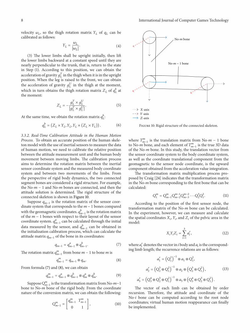
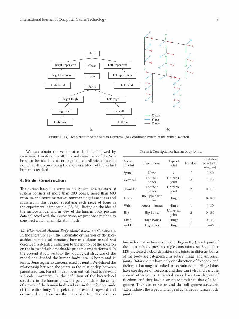
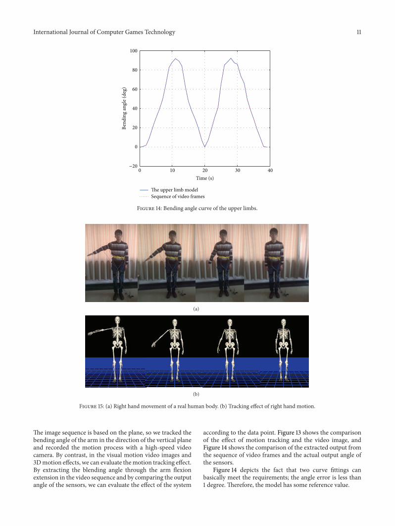

International Journal of
AerospaceEngineeringHindawi Publishing Corporationhttpwwwhindawicom Volume 2014
RoboticsJournal of
Hindawi Publishing Corporationhttpwwwhindawicom Volume 2014
Hindawi Publishing Corporationhttpwwwhindawicom Volume 2014
Active and Passive Electronic Components
Control Scienceand Engineering
Journal of
Hindawi Publishing Corporationhttpwwwhindawicom Volume 2014
International Journal of
RotatingMachinery
Hindawi Publishing Corporationhttpwwwhindawicom Volume 2014
Hindawi Publishing Corporation httpwwwhindawicom
Journal ofEngineeringVolume 2014
Submit your manuscripts athttpwwwhindawicom
VLSI Design
Hindawi Publishing Corporationhttpwwwhindawicom Volume 2014
Hindawi Publishing Corporationhttpwwwhindawicom Volume 2014
Shock and Vibration
Hindawi Publishing Corporationhttpwwwhindawicom Volume 2014
Civil EngineeringAdvances in
Acoustics and VibrationAdvances in
Hindawi Publishing Corporationhttpwwwhindawicom Volume 2014
Hindawi Publishing Corporationhttpwwwhindawicom Volume 2014
Electrical and Computer Engineering
Journal of
Advances inOptoElectronics
Hindawi Publishing Corporation httpwwwhindawicom
Volume 2014
The Scientific World JournalHindawi Publishing Corporation httpwwwhindawicom Volume 2014
SensorsJournal of
Hindawi Publishing Corporationhttpwwwhindawicom Volume 2014
Modelling amp Simulation in EngineeringHindawi Publishing Corporation httpwwwhindawicom Volume 2014
Hindawi Publishing Corporationhttpwwwhindawicom Volume 2014
Chemical EngineeringInternational Journal of Antennas and
Propagation
International Journal of
Hindawi Publishing Corporationhttpwwwhindawicom Volume 2014
Hindawi Publishing Corporationhttpwwwhindawicom Volume 2014
Navigation and Observation
International Journal of
Hindawi Publishing Corporationhttpwwwhindawicom Volume 2014
DistributedSensor Networks
International Journal of