Research Article Procedure of Active Residual Heat Removal ...
11
Research Article Procedure of Active Residual Heat Removal after Emergency Shutdown of High-Temperature-Gas-Cooled Reactor Xingtuan Yang, Yanfei Sun, Huaiming Ju, and Shengyao Jiang Key Laboratory of Advanced Reactor Engineering and Safety, Ministry of Education, Institute of Nuclear and New Energy Technology of Tsinghua University, Beijing 100084, China Correspondence should be addressed to Xingtuan Yang; [email protected] Received 10 November 2013; Accepted 13 June 2014; Published 7 July 2014 Academic Editor: Yanping Huang Copyright © 2014 Xingtuan Yang et al. is is an open access article distributed under the Creative Commons Attribution License, which permits unrestricted use, distribution, and reproduction in any medium, provided the original work is properly cited. Aſter emergency shutdown of high-temperature-gas-cooled reactor, the residual heat of the reactor core should be removed. As the natural circulation process spends too long period of time to be utilized, an active residual heat removal procedure is needed, which makes use of steam generator and start-up loop. During this procedure, the structure of steam generator may suffer cold/heat shock because of the sudden load of coolant or hot helium at the first few minutes. Transient analysis was carried out based on a one-dimensional mathematical model for steam generator and steam pipe of start-up loop to achieve safety and reliability. e results show that steam generator should be discharged and precooled; otherwise, boiling will arise and introduce a cold shock to the boiling tubes and tube sheet when coolant began to circulate prior to the helium. Additionally, in avoiding heat shock caused by the sudden load of helium, the helium circulation should be restricted to start with an extreme low flow rate; meanwhile, the coolant of steam generator (water) should have flow rate as large as possible. Finally, a four-step procedure with precooling process of steam generator was recommended; sensitive study for the main parameters was conducted. 1. Introduction In China, a commercial modular high-temperature-gas- cooled reactor pebble-bed module (HTR-PM) nuclear power plant entered its conceptual design phase in the year 2002 and aimed to complete a demonstration plant in 2012 [1]. Like other high-temperature-gas-cooled reactors (HTGR), HTR- PM has inherent negative temperature coefficient of reactivity of the core, which makes it have the unique characteristic of being able to remove the residual heat through the reactor vessel surface to the ultimate heat sink entirely by passive heat transfer mechanisms (radiation, convection, and conduction) [2]. However, the duration of passive heat transfer process will be hundreds of hours [3], which is too long to meet the requirement of rapid restart of the reactor aſter accident elimination. In the case of accidents (may be any kind that is able to induce the reaction of emergency system and cause shutdown of the core, such as loss of total electricity, earth quake, disabling of instruments, even false signals, etc.) happening in the nuclear part of the plant, the electric supply for both helium circulators of primary loop and feed water pump of secondary loop is available, and the steam generators (SG) and condenser are still functioning. ese conditions make it feasible to remove the residual heat of reactor core actively via SG and secondary loop rather than through passive natural heat transfer, in order to shorten the cooling process and reduce the time cost. is meets the economic consideration, which is one of the main design philosophies of HTR-PM [4]. For HTR-PM, the active residual heat removal process (ARHRP) can be accomplished by SG and start-up loop (STL), while the latter is designed for start process of the plant. Aſter the shutdown of the core in emergency, SG will be switched to connect with STL and insulated from the main steam loop (MSL). Residual heat of the core can be transferred to STL through SG in an active manner by the coolant circulation. However, the situation becomes very complex aſter core is shut down. First of all, the temperature distribution of boiling tubes of SG has a configuration with low temperature (205 ∘ C) at water inlet and high temperature (600 ∘ C) at steam outlet. Any inappropriate coolant flow into SG will cause heat/cold Hindawi Publishing Corporation Science and Technology of Nuclear Installations Volume 2014, Article ID 583597, 10 pages http://dx.doi.org/10.1155/2014/583597
Transcript of Research Article Procedure of Active Residual Heat Removal ...

Research ArticleProcedure of Active Residual Heat Removal after EmergencyShutdown of High-Temperature-Gas-Cooled Reactor
Xingtuan Yang, Yanfei Sun, Huaiming Ju, and Shengyao Jiang
Key Laboratory of Advanced Reactor Engineering and Safety, Ministry of Education,Institute of Nuclear and New Energy Technology of Tsinghua University, Beijing 100084, China
Correspondence should be addressed to Xingtuan Yang; [email protected]
Received 10 November 2013; Accepted 13 June 2014; Published 7 July 2014
Academic Editor: Yanping Huang
Copyright © 2014 Xingtuan Yang et al.This is an open access article distributed under the Creative Commons Attribution License,which permits unrestricted use, distribution, and reproduction in any medium, provided the original work is properly cited.
After emergency shutdown of high-temperature-gas-cooled reactor, the residual heat of the reactor core should be removed. Asthe natural circulation process spends too long period of time to be utilized, an active residual heat removal procedure is needed,whichmakes use of steam generator and start-up loop. During this procedure, the structure of steam generatormay suffer cold/heatshock because of the sudden load of coolant or hot helium at the first few minutes. Transient analysis was carried out based on aone-dimensional mathematical model for steam generator and steam pipe of start-up loop to achieve safety and reliability. Theresults show that steam generator should be discharged and precooled; otherwise, boiling will arise and introduce a cold shock tothe boiling tubes and tube sheet when coolant began to circulate prior to the helium. Additionally, in avoiding heat shock causedby the sudden load of helium, the helium circulation should be restricted to start with an extreme low flow rate; meanwhile, thecoolant of steam generator (water) should have flow rate as large as possible. Finally, a four-step procedure with precooling processof steam generator was recommended; sensitive study for the main parameters was conducted.
1. Introduction
In China, a commercial modular high-temperature-gas-cooled reactor pebble-bed module (HTR-PM) nuclear powerplant entered its conceptual design phase in the year 2002 andaimed to complete a demonstration plant in 2012 [1]. Likeother high-temperature-gas-cooled reactors (HTGR), HTR-PMhas inherent negative temperature coefficient of reactivityof the core, which makes it have the unique characteristic ofbeing able to remove the residual heat through the reactorvessel surface to the ultimate heat sink entirely by passive heattransfermechanisms (radiation, convection, and conduction)[2]. However, the duration of passive heat transfer processwill be hundreds of hours [3], which is too long to meetthe requirement of rapid restart of the reactor after accidentelimination. In the case of accidents (may be any kind thatis able to induce the reaction of emergency system andcause shutdown of the core, such as loss of total electricity,earth quake, disabling of instruments, even false signals, etc.)happening in the nuclear part of the plant, the electric supplyfor both helium circulators of primary loop and feed water
pumpof secondary loop is available, and the steam generators(SG) and condenser are still functioning. These conditionsmake it feasible to remove the residual heat of reactor coreactively via SG and secondary loop rather than throughpassive natural heat transfer, in order to shorten the coolingprocess and reduce the time cost. This meets the economicconsideration, which is one of the main design philosophiesof HTR-PM [4].
For HTR-PM, the active residual heat removal process(ARHRP) can be accomplished by SG and start-up loop(STL), while the latter is designed for start process of theplant. After the shutdown of the core in emergency, SG willbe switched to connect with STL and insulated from themain steam loop (MSL). Residual heat of the core can betransferred to STL through SG in an active manner by thecoolant circulation.
However, the situation becomes very complex after core isshut down. First of all, the temperature distribution of boilingtubes of SG has a configurationwith low temperature (205∘C)at water inlet and high temperature (600∘C) at steam outlet.Any inappropriate coolant flow into SG will cause heat/cold
Hindawi Publishing CorporationScience and Technology of Nuclear InstallationsVolume 2014, Article ID 583597, 10 pageshttp://dx.doi.org/10.1155/2014/583597
2 Science and Technology of Nuclear Installations
Steam generator
Reactor pressure vessel
Helium circulator
Condenser
Turbine
Pump
Water
SteamElectrical boiler
Discharge system
Separator
Reactor core
Steam discharge valve
Primary loopMain steam loop (MSL)
Water from start-up loop (STL)
Tube sheet
Preheater
Steam from start-up loop (STL)
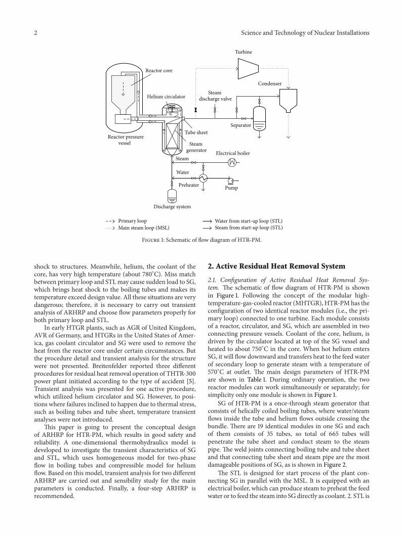
Figure 1: Schematic of flow diagram of HTR-PM.
shock to structures. Meanwhile, helium, the coolant of thecore, has very high temperature (about 780∘C). Miss matchbetween primary loop and STLmay cause sudden load to SG,which brings heat shock to the boiling tubes and makes itstemperature exceed design value. All these situations are verydangerous; therefore, it is necessary to carry out transientanalysis of ARHRP and choose flow parameters properly forboth primary loop and STL.
In early HTGR plants, such as AGR of United Kingdom,AVR of Germany, and HTGRs in the United States of Amer-ica, gas coolant circulator and SG were used to remove theheat from the reactor core under certain circumstances. Butthe procedure detail and transient analysis for the structurewere not presented. Breitenfelder reported three differentprocedures for residual heat removal operation of THTR-300power plant initiated according to the type of accident [5].Transient analysis was presented for one active procedure,which utilized helium circulator and SG. However, to posi-tions where failures inclined to happen due to thermal stress,such as boiling tubes and tube sheet, temperature transientanalyses were not introduced.
This paper is going to present the conceptual designof ARHRP for HTR-PM, which results in good safety andreliability. A one-dimensional thermohydraulics model isdeveloped to investigate the transient characteristics of SGand STL, which uses homogeneous model for two-phaseflow in boiling tubes and compressible model for heliumflow. Based on this model, transient analysis for two differentARHRP are carried out and sensibility study for the mainparameters is conducted. Finally, a four-step ARHRP isrecommended.
2. Active Residual Heat Removal System
2.1. Configuration of Active Residual Heat Removal Sys-tem. The schematic of flow diagram of HTR-PM is shownin Figure 1. Following the concept of the modular high-temperature-gas-cooled reactor (MHTGR), HTR-PMhas theconfiguration of two identical reactor modules (i.e., the pri-mary loop) connected to one turbine. Each module consistsof a reactor, circulator, and SG, which are assembled in twoconnecting pressure vessels. Coolant of the core, helium, isdriven by the circulator located at top of the SG vessel andheated to about 750∘C in the core. When hot helium entersSG, it will flow downward and transfers heat to the feed waterof secondary loop to generate steam with a temperature of570∘C at outlet. The main design parameters of HTR-PMare shown in Table 1. During ordinary operation, the tworeactor modules can work simultaneously or separately; forsimplicity only one module is shown in Figure 1.
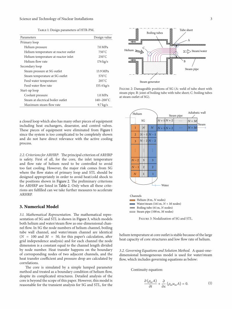
SG of HTR-PM is a once-through steam generator thatconsists of helically coiled boiling tubes, where water/steamflows inside the tube and helium flows outside crossing thebundle. There are 19 identical modules in one SG and eachof them consists of 35 tubes, so total of 665 tubes willpenetrate the tube sheet and conduct steam to the steampipe. The weld joints connecting boiling tube and tube sheetand that connecting tube sheet and steam pipe are the mostdamageable positions of SG, as is shown in Figure 2.
The STL is designed for start process of the plant con-necting SG in parallel with the MSL. It is equipped with anelectrical boiler, which can produce steam to preheat the feedwater or to feed the steam into SGdirectly as coolant. 2. STL is
Science and Technology of Nuclear Installations 3
Table 1: Design parameters of HTR-PM.
Parameters Design valuePrimary loop
Helium pressure 7.0MPaHelium temperature at reactor outlet 750∘CHelium temperature at reactor inlet 250∘CHelium flow rate 176 kg/s
Secondary loopSteam pressure at SG outlet 13.9MPaSteam temperature at SG outlet 570∘CFeed water temperature 205∘CFeed water flow rate 155.4 kg/s
Start-up loopCoolant pressure 1.0MPaSteam at electrical boiler outlet 140∼200∘CMaximum steam flow rate 9.7 kg/s
a closed loop which also has many other pieces of equipmentincluding heat exchangers, deaerator, and control valves.These pieces of equipment were eliminated from Figure 1since the system is too complicated to be completely shownand do not have direct relevance with the active coolingprocess.
2.2. Criterions for ARHRP. Theprincipal criterion of ARHRPis safety. First of all, for the core, the inlet temperatureand flow rate of helium need to be controlled to avoidtoo fast cooling. However, the major risk comes from SGwhere the flow states of primary loop and STL should bedesigned appropriately in order to avoid heat/cold shock tothe positions shown in Figure 2. The preliminary criterionsfor ARHRP are listed in Table 2. Only when all these crite-rions are fulfilled can we take further measures to accelerateARHRP.
3. Numerical Model
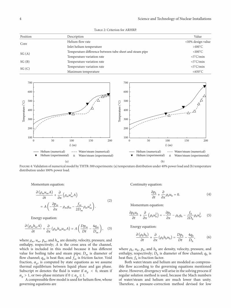
3.1. Mathematical Representation. The mathematical repre-sentation of SG and STL is shown in Figure 3, which modelsboth helium and water/steam flow as one-dimensional chan-nel flow. In SG the node numbers of helium channel, boilingtube wall channel, and water/steam channel are identical(𝑁 = 100 and 𝑀 = 50, for this paper’s calculation, aftergrid independence analysis) and for each channel the nodedimension is a constant equal to the channel length dividedby node number. Heat transfer happens on the boundaryof corresponding nodes of two adjacent channels, and theheat transfer coefficient and pressure drop are calculated bycorrelations.
The core is simulated by a simple lumped parametermethod and treated as a boundary condition of helium flow,despite its complicated structures. Detailed analysis of thecore is beyond the scope of this paper. However, this model isreasonable for the transient analysis for SG and STL, for the
A
B
CHelium Steam/water
Steam generator
Boiling tubesTube sheet
Steam pipe
Figure 2: Damageable positions of SG (A: weld of tube sheet withsteam pipe; B: joint of boiling tube with tube sheet; C: boiling tubesat steam outlet of SG).
1
2
3
3
21
Helium
Steam
Water
3
2 2
1
SGSteam pipe
Adiabatic wall
N − 2
N − 1
N
N − 2
N − 1
N
N − 2
N − 1
N
N + 1
N + 1
N + 2
N + 2
N + M
N + M
Helium (8 m, N nodes)Water/steam (161 m, N + M nodes)
Steam pipe (100 m, M nodes)
Channels
· · ·
· · ·
···
···
···
Boiling tube (61 m, N nodes)
Figure 3: Nodalization of SG and STL.
helium temperature at core outlet is stable because of the largeheat capacity of core structures and low flow rate of helium.
3.2. Governing Equations and Solution Method. A quasi-one-dimensional homogeneous model is used for water/steamflow, which includes governing equations as below:
Continuity equation:
𝜕 (𝜌
𝑚𝐴)
𝜕𝑡
+
𝜕
𝜕𝑥
(𝜌
𝑚𝑢
𝑚𝐴) = 0.
(1)
4 Science and Technology of Nuclear Installations
Table 2: Criterion for ARHRP.
Position Description Value
Core Helium flow rate <10% design valueInlet helium temperature >100∘C
SG (A) Temperature difference between tube sheet and steam pipe <100∘CTemperature variation rate <5∘C/min
SG (B) Temperature variation rate <5∘C/min
SG (C) Temperature variation rate <5∘C/minMaximum temperature <650∘C
500 100 150 200100
200
300
400
500
600
700
Helium (numerical)Helium (experimental)
Water/steam (numerical)Water/steam (experimental)
Tem
pera
ture
(∘C)
L (m)
(a)
500 100 150 200100
200
300
400
500
600
700
Helium (numerical)Helium (experimental)
Water/steam (numerical)Water/steam (experimental)
Tem
pera
ture
(∘C)
L (m)
(b)Figure 4: Validation of numericalmodel by THTR-300 experiments: (a) temperature distribution under 40% power load and (b) temperaturedistribution under 100% power load.
Momentum equation:
𝜕 (𝜌
𝑚𝑢
𝑚𝐴)
𝜕𝑡
+
𝜕
𝜕𝑥
(𝜌
𝑚𝑢
2
𝑚
𝐴)
= 𝐴(−
𝜕𝑝
𝑚
𝜕𝑥
− 𝜌
𝑚𝑔
𝑚−
𝑓
𝑚
2𝐷
𝑚
𝜌
𝑚𝑢
2
𝑚
) .
(2)
Energy equation:
𝜕 (𝜌
𝑚ℎ
𝑚𝐴)
𝜕𝑡
+
𝜕
𝜕𝑥
(𝜌
𝑚ℎ
𝑚𝑢
𝑚𝐴) = 𝐴(
𝐷𝑝
𝑚
𝐷𝑡
−
4𝑞
𝑚
𝐷
𝑚
) , (3)
where 𝜌𝑚, 𝑢𝑚, 𝑝𝑚, and ℎ
𝑚are density, velocity, pressure, and
enthalpy, respectively; 𝐴 is the cross area of the channel,which is included in this model because it has differentvalue for boiling tube and steam pipe; 𝐷
𝑚is diameter of
flow channel; 𝑞𝑚is heat flux; and 𝑓
𝑚is friction factor. Void
fraction, 𝛼𝑔, is computed by state equations as we assume
thermal equilibrium between liquid phase and gas phase.Subscript 𝑚 denotes the fluid is water if 𝛼
𝑔< 0, steam if
𝛼
𝑔> 1, or two-phase mixture if 0 ≤ 𝛼
𝑔≤ 1.
A compressible flowmodel is used for helium flow, whosegoverning equations are
Continuity equation:
𝜕𝜌
ℎ
𝜕𝑡
+
𝜕
𝜕𝑥
𝜌
ℎ𝑢
ℎ= 0.
(4)
Momentum equation:
𝜕𝜌
ℎ𝑢
ℎ
𝜕𝑡
+
𝜕
𝜕𝑥
(𝜌
ℎ𝑢
2
ℎ
) = −
𝜕𝑝
ℎ
𝜕𝑥
− 𝜌
ℎ𝑔
ℎ−
𝑓
ℎ
2𝐷
ℎ
𝜌
ℎ𝑢
2
ℎ
. (5)
Energy equation:
𝜕 (𝜌
ℎℎ
ℎ)
𝜕𝑡
+
𝜕
𝜕𝑥
(𝜌
ℎℎ
ℎ𝑢
ℎ) =
𝐷𝑝
ℎ
𝐷𝑡
−
4𝑞
ℎ
𝐷
ℎ
, (6)
where 𝜌ℎ, 𝑢ℎ, 𝑝ℎ, and ℎ
ℎare density, velocity, pressure, and
enthalpy, respectively; 𝐷ℎis diameter of flow channel; 𝑞
ℎis
heat flux; 𝑓ℎis fraction factor.
Both water/steam and helium are modeled as compress-ible flow according to the governing equations mentionedabove. However, divergency will arise in the solving process ifregular solution method is used, because the Mach numbersof water/steam and helium are much lower than unity.Therefore, a pressure-correction method devised for low

Science and Technology of Nuclear Installations 5
0 20 40 60 80 100 120 140 160100
200
300
400
500
600
700
800
Boiling tube/steam pipeWater/steam
Steam pipe
Tem
pera
ture
(∘C)
Boiling tube
L (m)
Figure 5: Temperature distribution of boiling tube and steam pipeafter shutdown of the core.
Mach number compressible problems is used in this paper,which was developed from the famous SIMPLE methodof Patankar and Spalding [6]. Additionally, staggered gridsystem and backward Euler implicit scheme for momentumequation and energy equation discretization are adopted toimprove the convergency. The code was validated by theexperimental results of THTR-300 steam generator, as shownin Figure 4. The predicted temperature distribution for bothhelium side and water side meet well with the experiments.
4. Transient Analysis of ARHRP
4.1. ARHRP without Precooling. As mentioned in Section 1,the temperature of SG tubes and steam pipe will be main-tained after the core is shutdown if without any furtheroperation, as shown in Figure 5. It is straight forward to runprimary loop and STL directly and simultaneously withoutany preconditioning of SG and STL, with the water/steamstaying in the boiling tube; for if flow parameters are designedappropriately, no obvious change would appear in the tem-perature distribution of SG and STL and consequently theheat/cold shock to structures due to the shift of flow stateswill be minimized.
However, in practice there must be a delay between thestarts of STL and primary loop. The feed water pump shouldbe started first in order to eliminate the risk of heat shockcaused by the high-temperature helium and overheating ofboiling tubes of SG (position C in Figure 2). This makesthe delay time be a crucial parameter, during which thetemperature of SG tubes decreases rapidly, as shown inFigure 6. For feed water flow rate being 10% design value, thetemperature of tubes at SG outlet will decrease from 570∘Cto 340∘C within only 3 minutes, and with the increase offeed water flow rate this process will be accelerated further.This phenomenon is caused by boiling. After shutdown of thecore, water occupies downside of the boiling tube and steamoccupies upside; at the interface of them water and steam are
0 20 40 60 80 100 120 140 160 180300
350
400
450
500
550
600
650
700
Tem
pera
ture
(∘C)
Time (s)
Water flow rate:10% design value20% design value
Figure 6: Temperature transient of boiling tube (steam outlet)during delay time; helium flow rate: 0; feed water temperature:105∘C; and pressure: 13.9MPa.
0 5 10 15 20300
350
400
450
500
550
600
650
700
Tem
pera
ture
(∘C)
Time (min)
Water flow rate:10% design value20% design value
Figure 7: Temperature transient of boiling tube (steam outlet), with30 s delay of helium circulation; helium flow rate: 10% design value;feed water temperature: 105∘C; and pressure: 13.9MPa.
still saturated and boiling will occur when water is heatedby the tube during proceeding upward (toward the hot end)driven by the pump. Tube’s temperature in the boiling areawill experience a sharp decrease because of the large heattransfer coefficient. Thus a cold shock is introduced, whichproceeds as fast as water/steam interface.
To decrease the feed water’s flow rate is helpful topostpone the cold shock. However, the minimum flow rateof feed water is limited to be not less than 10% of designvalue to avoid two-phase flow instabilities. The only wayto exclude the cold shock when water exists in the boiling

6 Science and Technology of Nuclear Installations
Step 1 Step 2 Step 3 Step 4discharge
waterdepressurize
SGprecooling
of SGcooling of
core
Figure 8: ARHRP with precooling of SG.
0 1 2 3 4 5 6 7 8550
560
570
580
590
600
610
620
Temperature (tube sheet of SG)Valve is opened 50%Valve is opened 100%
PressureValve is opened 50%Valve is opened 100%
Time (min)
Tem
pera
ture
(∘C)
1
2
3
4
5
6
7
8
9
Pres
sure
(MPa
)
Figure 9: Temperature and pressure transient during depressuriza-tion.
tubes is to shorten the delay time as much as possible. Thisis a rigid demand for the reliability of controls system andhelium circulator. Even though the circulator is started inthe permit time, the temperature variation of boiling tubesis still difficult to control, as shown in Figure 7. It is in adilemma that large feed water flow rate aggravates the coldshock and low feed water flow rate makes the boiling tube beoverheated. Furthermore, if helium circulator fails to start ina short time, this process must be interrupted and cannot berepeated because the permit delay time was already passed.Therefore this process is not reliable.
4.2. ARHRP with Precooling. To cool down boiling tubes andsteam pipe before the coolant enters SG is a fundamental wayto eliminate the risk of cold shock. Therefore we consideredincluding a precooling process and presented a four-stepARHRP as shown in Figure 8. Boiling will occur if water staysin boiling tubes of SG, which is unfavorable as analyzed forARHRP without precooling in Section 4.1. Hence we chooseto dischargewater fromSG in the first step and then use steamas coolant to cool down SG and STL slowly. As the steamis supplied by the electrical boiler of STL with a pressure ofabout 1MPa, the SG and STL should be depressurized in thesecond step. In the following, each step of ARHRP will beanalyzed in detail.
Step 1. Discharge liquid water from SG. This step is accom-plished by discharge system, which can remove the waterentirely in no more than one minute, which occupies 2/3space of boiling tube after shutdown of reactor core. At the
0 30 60 90 120 150 180 210 240
Time (min)
200
250
300
350
400
450
500
550
600
650
Tem
pera
ture
(∘C)
Tube sheetSteam pipe (SG outlet)
Figure 10: Temperature variation of SG outlet during precoolingusing steam as coolant; steam temperature: 190∘C; pressure: 1.0MPa;and flow rate: 0.74 kg/s.
0 30 60 90 120 150 180 210 240
Time (min)
−40
−20
0
20
40
60
80
100
Tem
pera
ture
(∘C)
Temperature difference between steam pipe and tube sheet
Figure 11: Temperature difference of steam pipe and tube sheetduring precooling using steam as coolant; steam temperature: 190∘C;pressure: 1.0MPa; and flow rate: 0.74 kg/s.
end of this step the pressure in SGs boiling tube and STL willbe reduced to about 8MPa, while the temperature variationof SG tubes and tube sheet is neglectable for the water isdischarged from bottom (cold end) of SG and the durationis very short.
Step 2. Depressurize SG and STL. Through the dischargevalve on the steam pipe, steam in SG and STL can be dis-charged to the ambient directly, until the pressure decreasesto be lower than 1MPa. The speed of depressurization canbe controlled through adjusting the valve’s open degree, asshown in Figure 9. The temperature decreased about 15∘C inthis step and the speed meets the demands listed in Table 2even when the valve is fully opened.
Science and Technology of Nuclear Installations 7
0 2 4 6 8 10 12 14 16 18 20
Time (min)
100
200
300
400
500
600
700
800
Tem
pera
ture
(∘C)
Water mass flow rate: 10% design valueWater inlet temperature: 105
∘CHelium flow rate: 10% design value
HeliumBoiling tubeWater/steam
(a)
0 20 40 60 80 100 120 140
Time (s)
−100
0
100
200
300
400
500
Mas
s velo
city
(kg/
(m2
s))
(b)
0 2 4 6 8 10 12 14 16 18 20
Time (min)
0
100
200
300
400
Tem
pera
ture
(∘C)
Temperature difference between tube sheet and steam pipe
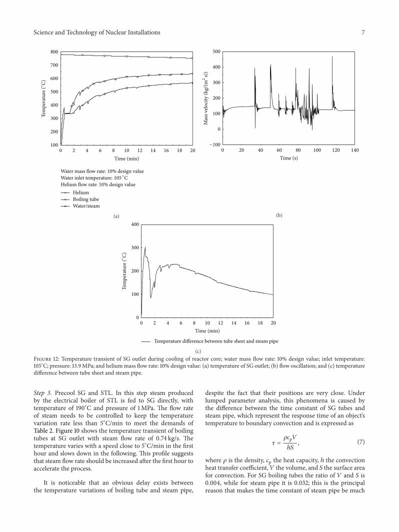
(c)Figure 12: Temperature transient of SG outlet during cooling of reactor core; water mass flow rate: 10% design value; inlet temperature:105∘C; pressure: 13.9MPa; and heliummass flow rate: 10% design value: (a) temperature of SG outlet; (b) flow oscillation; and (c) temperaturedifference between tube sheet and steam pipe.
Step 3. Precool SG and STL. In this step steam producedby the electrical boiler of STL is fed to SG directly, withtemperature of 190∘C and pressure of 1MPa. The flow rateof steam needs to be controlled to keep the temperaturevariation rate less than 5∘C/min to meet the demands ofTable 2. Figure 10 shows the temperature transient of boilingtubes at SG outlet with steam flow rate of 0.74 kg/s. Thetemperature varies with a speed close to 5∘C/min in the firsthour and slows down in the following. This profile suggeststhat steam flow rate should be increased after the first hour toaccelerate the process.
It is noticeable that an obvious delay exists betweenthe temperature variations of boiling tube and steam pipe,
despite the fact that their positions are very close. Underlumped parameter analysis, this phenomena is caused bythe difference between the time constant of SG tubes andsteam pipe, which represent the response time of an object’stemperature to boundary convection and is expressed as
𝜏 =
𝜌𝑐
𝑝𝑉
ℎ𝑆
,(7)
where 𝜌 is the density, 𝑐𝑝the heat capacity, ℎ the convection
heat transfer coefficient,𝑉 the volume, and 𝑆 the surface areafor convection. For SG boiling tubes the ratio of 𝑉 and 𝑆 is0.004, while for steam pipe it is 0.032; this is the principalreason that makes the time constant of steam pipe be much
8 Science and Technology of Nuclear Installations
0 10 20 30 40 50 60
Time (min)
100
200
300
400
500
600Te
mpe
ratu
re (∘
C)
Helium flow rate: 2% design valueWater flow rate:
10% design value30% design value30% design value (helium flow gradually increased)
(a)
0 30 600
1
2
3
Mas
s flow
rate
(% d
esig
n va
lue)
Time (min)
(b)
0 10 20 30 40 50 60
Time (min)
0
50
100
150
200
Tem
pera
ture
(∘C)
Helium flow rate: 2% design valueWater flow rate:
10% design value30% design value30% design value (helium flow gradually increased)
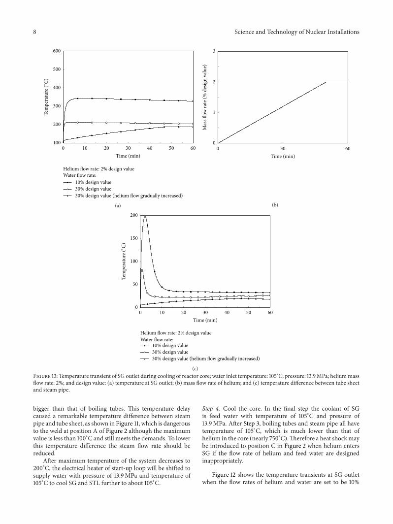
(c)Figure 13: Temperature transient of SG outlet during cooling of reactor core; water inlet temperature: 105∘C; pressure: 13.9MPa; heliummassflow rate: 2%; and design value: (a) temperature at SG outlet; (b) mass flow rate of helium; and (c) temperature difference between tube sheetand steam pipe.
bigger than that of boiling tubes. This temperature delaycaused a remarkable temperature difference between steampipe and tube sheet, as shown in Figure 11, which is dangerousto the weld at position A of Figure 2 although the maximumvalue is less than 100∘C and still meets the demands. To lowerthis temperature difference the steam flow rate should bereduced.
After maximum temperature of the system decreases to200∘C, the electrical heater of start-up loop will be shifted tosupply water with pressure of 13.9MPa and temperature of105∘C to cool SG and STL further to about 105∘C.
Step 4. Cool the core. In the final step the coolant of SGis feed water with temperature of 105∘C and pressure of13.9MPa. After Step 3, boiling tubes and steam pipe all havetemperature of 105∘C, which is much lower than that ofhelium in the core (nearly 750∘C).Therefore a heat shockmaybe introduced to position C in Figure 2 when helium entersSG if the flow rate of helium and feed water are designedinappropriately.
Figure 12 shows the temperature transients at SG outletwhen the flow rates of helium and water are set to be 10%

Science and Technology of Nuclear Installations 9
of design value, respectively. In the first minute boiling tube’stemperature rises rapidly to nearly 400∘C due to the suddenload of hot helium and then decreases to 340∘C abruptlywhen water began to boil. After that, a staggered temperatureprofile arises and lasts about 10 minutes, accompanied withthe oscillation ofmass flow rate of steamat boiling tube outlet.The oscillation was caused by the two-phase flow instabilitiesbecause of the low mass flow rate of water. Meanwhile themaximum temperature difference between tube sheet of SGand steam pipe enlarges to 300∘C. Obviously this process isunacceptable.
This series of problems is caused by big helium flow ratecombined with small water flow rate. Figure 13 shows thetemperature transient of SG steam outlet with helium flowrate being 2%of design value. Comparedwith Figure 12(a) theheat shock is alleviated and reduced further with the increaseof water flow rate. However, this is still not sufficient to elim-inate the heat shock. The helium flow must be controlled toincrease slowly from a tiny flow rate as shown in Figure 13(b).Under such operation the temperature difference of SG tubesheet and steam pipe can be confined within 25∘C.Thereforethe combination of big water flow rate and gradual increaseof helium flow from tiny flow rate is the optimum option forthis step. However, the present helium circulator may havedifficulties to work under so small flow rate. To accomplishthis step a smaller circulator should be supplemented to thissystem.
5. Conclusion
In the present work the ARHRP of HTR-PM has been stud-ied theoretically based on a one-dimensional mathematicalmodel. Transient analysis was carried out for the wholeprocess and following conclusions were obtained.
(1) Boiling is unfavorable for ARHRP, due to both thecold shock to the hot structures induced by largeheat transfer coefficient and potential two-phase flowinstabilities when feed water flow rate is low. Actually,safety is principal for ARHRP which demands toexclude any fast heat transfer process.
(2) Tube sheet at steam outlet of SG is one of the mostdamageable positions during ARHRP, for its weldswith boiling tubes and steam pipe will suffer thermalstress caused by the temperature differences. Partic-ularly, according to the fact that the time constant oftube sheet is much smaller than that of steam pipe,an obvious delay of temperature variation appears andmakes the temperature difference between these twoobjects remarkable.
(3) For ARHRP without precooling of SG and STL,boiling and cold shock are inevitable when waterbegins to proceed in the hot boiling tubes beforehelium begins to circulate. Although the cold shockcan be alleviated through shortening the start time ofhelium circulator, this type ARHRP is not robust.
(4) A four-step ARHRP with precooling of SG and STLcan eliminate the cold shock fundamentally. In pre-cooling process steam is used as the coolant tomake sure no cold shock will be introduced. Afterthat, the main consideration is to avoid the heatshock to boiling tubes and tube sheet at steam outletwhen the hot helium enters SG. A combination oflarge feed water flow and gradually increased heliumflow can eliminate the hot shock and confine thetemperature difference between tube sheet and steampipe effectively. This type ARHRP is recommendedin this paper, although a new helium circulatorwhich can supply small helium flow rate should besupplemented to this system.
This work is instructive to the engineering design ofARHRP for HTR-PM, which can shorten the cooling timeof reactor core and improve the economic performance ofthe plant. However, more detailed calculations are needed tospecify the flow parameters for each step of ARHRP.
Nomenclature
𝐴: Cross area [m2]𝑐
𝑝: Specific heat capacity [J/(kg⋅K)]𝐷: Diameter [m]𝑓: Friction factor𝑔: Gravity [m/s2]ℎ: Specific enthalpy [J/kg]𝑀: Node number of steam pipes𝑁: Node number of boiling tube𝑝: Pressure [Pa]𝑞: Heat flux [W/m2]𝑆: Surface area [m2]𝑉: Volume [m3].
Greek Letters
𝛼
𝑔: Void fraction𝜌: Density [kg/m3]𝜏: Time constant [s].
Subscripts
𝑔: Vapor𝑚: Mixture of liquid phase and vapor phaseℎ: Helium.
Conflict of Interests
The authors declare that there is no conflict of interestsregarding the publication of this paper.
Acknowledgments
This work was supported by Ph.D. Program Foundation ofMinistry of Education of China (no. 20100002120036) andResearch Project of Tsinghua University (no. 2012Z02145).
10 Science and Technology of Nuclear Installations
References
[1] Z. Zhang, Z. Wu, Y. Sun, and F. Li, “Design aspects of theChinese modular high-temperature gas-cooled reactor HTR-PM,”Nuclear Engineering and Design, vol. 236, no. 5-6, pp. 485–490, 2006.
[2] H. Niessen and S. Ball, “Heat transport and afterheat removalfor gas cooled reactors under accident conditions,” Tech. Rep.IAEA-TECDOC-1163, International Atomic Energy Agency,Vienna, Austria, 2000.
[3] Y. Qingliao, X. Zhao, W. Xinxin, H. Shuyan, and S. Yuliang,“Design of pre-stressed concrete pressure vessel residual heatremoval system formodular high-temperature gas-cooled reac-tor,”Atomic Energy Science and Technology, vol. 41, no. 1, pp. 74–78, 2007.
[4] Z. Zhang and Y. Sun, “Economic potential of modular reactornuclear power plants based on the Chinese HTR-PM project,”Nuclear Engineering and Design, vol. 237, no. 23, pp. 2265–2274,2007.
[5] R. Breitenfelder, W. Wachholz, and U. Weicht, “Accident anal-ysis and accident control for the THTR-300 power plant,” inProceedings of the Specialists Meeting on Gas-Cooled ReactorSafety and Licensing Aspects, Lausanne, Switzerland, 1980.
[6] J. J. McGuirk and G. J. Page, “Shock capturing using a pressure-correction method,” AIAA journal, vol. 28, no. 10, pp. 1751–1757,1990.

TribologyAdvances in
Hindawi Publishing Corporationhttp://www.hindawi.com Volume 2014
International Journal of
AerospaceEngineeringHindawi Publishing Corporationhttp://www.hindawi.com Volume 2014
FuelsJournal of
Hindawi Publishing Corporationhttp://www.hindawi.com Volume 2014
Journal ofPetroleum Engineering
Hindawi Publishing Corporationhttp://www.hindawi.com Volume 2014
Industrial EngineeringJournal of
Hindawi Publishing Corporationhttp://www.hindawi.com Volume 2014
Power ElectronicsHindawi Publishing Corporationhttp://www.hindawi.com Volume 2014
Advances in
CombustionJournal of
Hindawi Publishing Corporationhttp://www.hindawi.com Volume 2014
Journal of
Hindawi Publishing Corporationhttp://www.hindawi.com Volume 2014
Renewable Energy
Submit your manuscripts athttp://www.hindawi.com
Hindawi Publishing Corporationhttp://www.hindawi.com Volume 2014
StructuresJournal of
International Journal of
RotatingMachinery
Hindawi Publishing Corporationhttp://www.hindawi.com Volume 2014
EnergyJournal of
Hindawi Publishing Corporationhttp://www.hindawi.com Volume 2014
Hindawi Publishing Corporation http://www.hindawi.com
Journal ofEngineeringVolume 2014
Hindawi Publishing Corporation http://www.hindawi.com Volume 2014
International Journal ofPhotoenergy
Hindawi Publishing Corporationhttp://www.hindawi.com Volume 2014
Nuclear InstallationsScience and Technology of
Hindawi Publishing Corporationhttp://www.hindawi.com Volume 2014
Solar EnergyJournal of
Hindawi Publishing Corporationhttp://www.hindawi.com Volume 2014
Wind EnergyJournal of
Hindawi Publishing Corporationhttp://www.hindawi.com Volume 2014
Nuclear EnergyInternational Journal of
Hindawi Publishing Corporationhttp://www.hindawi.com Volume 2014
High Energy PhysicsAdvances in
The Scientific World JournalHindawi Publishing Corporation http://www.hindawi.com Volume 2014