Research Article Prediction of Mold Spoilage for Soy ...
12
Research Article Prediction of Mold Spoilage for Soy/Polyethylene Composite Fibers Chinmay Naphade, 1 Inyee Han, 2 Sam Lukubira, 3 Amod Ogale, 3 James Rieck, 4 and Paul Dawson 2 1 Farbest Foods, Jasper, IN 47546, USA 2 Food, Nutrition and Packaging Sciences, Clemson University, Clemson, SC 29634, USA 3 Chemical and Biomolecular Engineering, Clemson University, Clemson, SC 29634, USA 4 Department of Mathematics, Clemson University, Clemson, SC 29634, USA Correspondence should be addressed to Paul Dawson; [email protected] Received 1 September 2014; Accepted 19 December 2014 Academic Editor: Long Yu Copyright © 2015 Chinmay Naphade et al. is is an open access article distributed under the Creative Commons Attribution License, which permits unrestricted use, distribution, and reproduction in any medium, provided the original work is properly cited. Mold spoilage was determined over 109 days on soy/PE fibers held under controlled temperatures (T) ranging from 10 ∘ C to 40 ∘ C and water activities ( ) from 0.11 to 0.98. Water activities were created in sealed containers using saturated salt solutions and placed in temperature-controlled incubators. Soy/PE fibers that were held at 0.823 or higher exhibited mold growth at all temperatures. As postulated, increased water activity (greater than 0.89) and temperature (higher than 25 ∘ C) accelerated mold growth on soy/PE fibers. A slower mold growth was observed on soy/PE fibers that were held at 0.87 and 10 ∘ C. A Weibull model was employed to fit the observed logarithmic values of , , and an interaction term log × log and was chosen as the final model as it gave the best fit to the raw mold growth data. ese growth models predict the expected mold-free storage period of soy/PE fibers when exposed to various environmental temperatures and humidities. 1. Introduction Natural/biofiber composites are emerging as a viable alter- native to glass fiber composites, particularly in automo- tive, packaging, building, and consumer product industries becoming one of the fastest growing additives for thermo- plastics. Biocomposites can mimic the structures of living materials by providing strengthening properties to the matrix while still providing biocompatibility, for example, in creating scaffolds in bone tissue engineering [1] (Kispotta and Bisoyi, 2011). Biocomposites are composite materials that contain one or more phase(s) derived from a biological origin [2]. For biocomposites the reinforcement could be fibers like cotton, flax, hemp, wood, or even by-products from food crops. Matrices may be polymers, ideally derived from renewable resources such as vegetable oils or starches. One of the most commonly used matrices is synthetic, fossil-derived poly- mers. Biocomposites integrate “soſt” biological and organic molecular assemblies with “hard” inorganic nanoarchitec- tures combining materials having disparate chemical and physical properties within a single system. e addition of natural fillers or reinforcements is pos- tulated to lower the manufacturing cost and increase the stiffness of composites [3]. Fillers also provide advantages of lower energy consumption and faster cycle time during pro- duction. Another major advantage of these reinforcements is incorporation of biopolymers such as starches and proteins into composites enhancing degradation of plastic materials [4]. Several studies have reported on the incorporation of biopolymers, such as starch and protein, into extrusion blown polyethylene films [5, 6]. Films combining protein with synthetic plastics show potential for production of compostable plastic materials. Degradation of proteins by microorganisms can render the remaining synthetic polymer vulnerable to photodegradation or thermal degradation. Hindawi Publishing Corporation International Journal of Polymer Science Volume 2015, Article ID 176826, 11 pages http://dx.doi.org/10.1155/2015/176826
Transcript of Research Article Prediction of Mold Spoilage for Soy ...

Research ArticlePrediction of Mold Spoilage for Soy/PolyethyleneComposite Fibers
Chinmay Naphade,1 Inyee Han,2 Sam Lukubira,3 Amod Ogale,3
James Rieck,4 and Paul Dawson2
1Farbest Foods, Jasper, IN 47546, USA2Food, Nutrition and Packaging Sciences, Clemson University, Clemson, SC 29634, USA3Chemical and Biomolecular Engineering, Clemson University, Clemson, SC 29634, USA4Department of Mathematics, Clemson University, Clemson, SC 29634, USA
Correspondence should be addressed to Paul Dawson; [email protected]
Received 1 September 2014; Accepted 19 December 2014
Academic Editor: Long Yu
Copyright © 2015 Chinmay Naphade et al. This is an open access article distributed under the Creative Commons AttributionLicense, which permits unrestricted use, distribution, and reproduction in any medium, provided the original work is properlycited.
Mold spoilage was determined over 109 days on soy/PE fibers held under controlled temperatures (T) ranging from 10∘C to 40∘Candwater activities (𝑎
𝑤
) from 0.11 to 0.98.Water activities were created in sealed containers using saturated salt solutions and placedin temperature-controlled incubators. Soy/PE fibers that were held at 0.823 𝑎
𝑤
or higher exhibited mold growth at all temperatures.As postulated, increased water activity (greater than 0.89) and temperature (higher than 25∘C) accelerated mold growth on soy/PEfibers. A slower mold growth was observed on soy/PE fibers that were held at 0.87 𝑎
𝑤
and 10∘C. A Weibull model was employedto fit the observed logarithmic values of 𝑇, 𝑎
𝑤
, and an interaction term log𝑇 × log 𝑎𝑤
and was chosen as the final model as it gavethe best fit to the rawmold growth data.These growth models predict the expected mold-free storage period of soy/PE fibers whenexposed to various environmental temperatures and humidities.
1. Introduction
Natural/biofiber composites are emerging as a viable alter-native to glass fiber composites, particularly in automo-tive, packaging, building, and consumer product industriesbecoming one of the fastest growing additives for thermo-plastics. Biocomposites can mimic the structures of livingmaterials by providing strengthening properties to thematrixwhile still providing biocompatibility, for example, in creatingscaffolds in bone tissue engineering [1] (Kispotta and Bisoyi,2011). Biocomposites are composite materials that containone ormore phase(s) derived from a biological origin [2]. Forbiocomposites the reinforcement could be fibers like cotton,flax, hemp, wood, or even by-products from food crops.Matrices may be polymers, ideally derived from renewableresources such as vegetable oils or starches. One of the mostcommonly used matrices is synthetic, fossil-derived poly-mers. Biocomposites integrate “soft” biological and organic
molecular assemblies with “hard” inorganic nanoarchitec-tures combining materials having disparate chemical andphysical properties within a single system.
The addition of natural fillers or reinforcements is pos-tulated to lower the manufacturing cost and increase thestiffness of composites [3]. Fillers also provide advantages oflower energy consumption and faster cycle time during pro-duction. Another major advantage of these reinforcements isincorporation of biopolymers such as starches and proteinsinto composites enhancing degradation of plastic materials[4].
Several studies have reported on the incorporation ofbiopolymers, such as starch and protein, into extrusionblown polyethylene films [5, 6]. Films combining proteinwith synthetic plastics show potential for production ofcompostable plastic materials. Degradation of proteins bymicroorganisms can render the remaining synthetic polymervulnerable to photodegradation or thermal degradation.
Hindawi Publishing CorporationInternational Journal of Polymer ScienceVolume 2015, Article ID 176826, 11 pageshttp://dx.doi.org/10.1155/2015/176826

2 International Journal of Polymer Science
Gurram et al. (2002) [7] studied the properties of wood,soy hull fiber, and big blue stem on the tensile and flexuralproperties of fibers. They found that Young’s modulus ofwood, big blue stem, and soy hull fiber composites werecomparable to pure polypropylene and polyethylene. Theseresearchers also concluded that biorenewable fibers such assoybean hulls could be used as reinforcing materials for lowcost composites and that environmental and energy savingsbenefits could be another advantage of biocomposites. Zhanget al. (1999) [8] studied biocomponent fibers that were wet-spun from soybean protein and poly(vinyl alcohol) for textileapplications. They determined that the protein core of thespun biocomponent fiber was brittle and showed a highfrequency of core breakage upon drawing.Thus an effort wasmade to investigate the soybean protein solution, with theaim of trying to understand the cause for fiber brittlenessand to determine the optimum solution conditions for fiberspinning.
Ghorpade et al. (1995) [9] evaluated the cast formingability of soy protein isolates with varying amounts ofpolyethylene oxides (PEO) and determined that additionof PEO decreased film tensile strength (TS) and increasedelongation at break (𝐸). Scanning electron micrographs offilm cross-sections showed a decrease in positive textureattributes with increasing amounts of PEO in the films. Jong(2005) [10] used defatted soy flour (DSF) for rubber reinforce-ments. The reinforcement mechanism of DSF in rubber usedcarboxylated polystyrene-butadiene as a composite matrixand was characterized by static and dynamic mechanicalmethods. These results indicated that DSF was a moreeffective option than either soy protein isolate or concentratein terms of both mechanical properties and cost.
The growth of microorganisms like bacteria or molds ona substrate is governed by the intrinsic and extrinsic factors[11, 12]. Following are the important intrinsic factors:
(i) moisture content,(ii) nutrient content,(iii) oxidation-reduction potential (Eh)(iv) pH.
Extrinsic factors influencing microbial growth are
(i) temperature,(ii) relative humidity,(iii) presence and concentration of gases,(iv) presence and activities of other microorganisms.
Mold can grow on many surfaces where oxygen andmoisture are present. Biocomposites are more susceptibleto microbial growth than fossil-derived polymers due totheir hydrophilic nature and nutrient availability. Moisturesorption isotherms have been studied for a range of biologicalmaterials including starch powders [13, 14], pasta [15], tealeaves [16], corn stover [17], alfalfa cubes [18], oats/oatmealbiscuits [19], bean flour [20], and cookies [21]. Moisturesorption isotherms have also been used to study bio-basedfilms formed from starch [22], whey protein [23], chicken
feather keratin [24], and zein [25]. Models predicting moldgrowth under various moisture conditions have also beendeveloped [26].
Igathinathane et al. (2008) [27] developed a model topredict the storage life of corn stover components withoutmold growth when exposed to different temperature andhumidity conditions. In order to maintain humidity condi-tions, saturated salts solutions were placed in temperaturecontrolled chambers. The desiccators were used to createenvironments having temperatures from 10∘C to 40∘C and 𝑎
𝑤
of 0.11 to 0.98. At a high water activity (>0.90 𝑎𝑤) and a tem-
perature of 30∘C, mold growth occurred in corn leaf, stalk,and skin rapidly. One-, two-, and three-parameter modelswere assessed for their performance to predictmold-free days(MFDs) based on temperature and 𝑎
𝑤. The three-parameter
model gave the best prediction compared to the exponentialmodel.The single parameter 𝑇×𝑎
𝑤product model produced
slightly better results than the two-parameter model. Three-parameter model featured all parameters and the 𝑡-statisticsrevealed that the combined 𝑇 × 𝑎
𝑤product variable was
more significant than variables of 𝑇 and 𝑎𝑤. They concluded
that a predictive model could be utilized to predict the safestorage period of corn stover components under controlledtemperature and 𝑎
𝑤conditions.
Various authors [28–30] reviewed different mathematicalisotherm models that can be used to predict the stabilityof biological materials. Though several articles have beenstudied, there is no single model identified that can describethe sorption characteristics of soy composites. Thus, theobjective of the present study was to develop statistical modelto predict mold-free shelf life of soy/PE based as influencedby temperature and water activity.
2. Materials and Methods
2.1. Production of Soy/PE Fibers. Soy flour, grade of 7B2,was provided by ADM (Archer Daniels Midland Company,USA). Linear low density PE, ASPUN grade, was providedby Dow Chemicals (Bristol, Pennsylvania). All fibers wereproduced at ClemsonUniversity Chemical and BiomolecularEngineering. Soy/PE fibers were produced using a propri-etary blending of defatted soy flour, a spun pure PE pellets,and a compatibilizer. These materials were blended togetherusing a DSM compounder twin screwmicroextruder (XplorePharma, RD Geleen, Netherlands), to obtain dispersion ofsoy particles in PE phase.The blended materials were furtherextruded using a pilot scale single screw extruder (Alex James& Associates, Greenville, SC) to melt spin soy/PE fibers andpure PE fibers. Pellets were fed to single screw extruder thatwas designed to deliver molten soy/PE mixture at constantpressure to themelting pump.The extruder die had three 500micron diameter openings to extrude fibers. Fibers were thenspun on a continuously spinning unit with a take-up of spe-cific revolutions per minutes (rpm), reducing fiber diameter.This process yielded consistent fibers having a diameter of50–100 microns, which were further spun on a clean spool.
2.2. Saturated Salt Solutions. Individual containers (16 ouncepint Mason Jars, Ball, Rome, Georgia) were used to hold fiber

International Journal of Polymer Science 3
Table 1: Water activity of saturated salt solutions at five differenttemperatures.
Saturated salt solution Water activity10∘C 25∘C 30∘C 35∘C 40∘C
Lithium chloride 0.113 0.113 0.113 0.113 0.112Potassium acetate 0.234 0.225 0.216 0.216 0.216Magnesium chloride 0.335 0.328 0.324 0.321 0.316Potassium carbonate 0.431 0.432 0.432 0.41 0.40Sodium bromide 0.622 0.576 0.560 0.546 0.532Sodium chloride 0.757 0.753 0.751 0.749 0.747Potassium chloride 0.868 0.843 0.836 0.830 0.823Potassium nitrate 0.960 0.936 0.923 0.908 0.890Potassium sulfate 0.982 0.973 0.970 0.967 0.964
samples. The various water activities were created by theaddition of nine different salts (lithium chloride, potassiumacetate, magnesium chloride, potassium carbonate, sodiumbromide, sodium chloride, potassium chloride, potassiumnitrate, and potassium sulfate) in 70mL of nanopure wateruntil each solution was saturated. Salts and water solutionswere vigorously agitated using magnetic stirrer to facilitatesaturation. Additional salt was added as initially added saltsdissolved in water to maintain saturation. Saturated salt solu-tions were placed in temperatures of 10, 25, 30, 35, and 40∘C.Once saturated salt solutions became temperature equili-brated, 𝑎
𝑤ranging from 0.11 to 0.98 was generated depending
upon the salt and temperature combination (Table 1).
2.3. Sample Preparation. Soy/PE and pure PE fibers werecarefully removed from the spool using sterile gloves asreceived from production. 1.000 g of fiber was weighed on adigital balance with a sensitivity of 0.0001 g. Fiber sampleswere prepared from soy/PE fiber spool and stored in asterile glass holder. Fiber samples were weighed and allnecessary information such as initial weight before drying,final weight after drying, and the sample number wasmarked onto the glass holders. Samples were loaded into aconvection oven (Thelco Laboratory Oven 130DM, PrecisionScientific, Chicago, Illinois) at 55∘C for 15 hrs to equilibratefiber moisture content to <0.1%. Fibers were then held ina desiccator for 1 hr to cool. Fiber samples were reweighedplaced in a sterilized aluminum pans and were randomizedusing randomnumber generator statistical software [31] (SAS9.3, 2012).
Initially fiber samples that were predried were placed innine different salt solution containers (Figure 1) at tempera-tures of 10, 25, 30, 35, and 40∘C (Gravity Convection Incu-bator 1.1CF120, VWR, Atlanta, GA). Water activities rangedfrom 0.11 to 0.98 depending upon the salt and temperaturecombination. Soy/PE fiber samples were placed in all theabove-mentioned conditions for 50 days to examine the rangeof water activity at which mold spoilage was observed onsoy/PE fibers. The experiment was run twice independentlywith a fresh spool of soy/PE fiber for each replication. Fibersthat were stored in high 𝑎
𝑤(in a range of 0.8–0.98) exhibited
Airtight lid
Aluminum pan (sample)
Glass bottle
Saturated salt solution
Chemicals
Figure 1: Experimental setup for establishing different water activ-ities in containers using different saturated salt solutions. One gramof soy/PE fiber sample was placed in each jar in aluminum pans.
mold growth and hence a separate experiment (that wasreplicated 3 times) was conducted to develop a model thatcould precisely predict the onset of mold growth in soy/PEfibers.
2.4. Experimental Setup. 30 soy/PE fiber samples placed inthe desiccator for 1 hr were reweighed in aluminum pansbefore they were loaded into saturated salt solution contain-ers. Before loading into saturated salt solution containers,soy/PE fiber samples were randomized as mentioned abovein sample preparation. Weighing process was critical andhence was carried out quickly as fibers were dry in natureand long-term exposure to laboratory air could have led toreabsorption of moisture. A one ounce small glass (AnchorHocking number 82412) was placed into the saturated solu-tion with an aluminum pan containing fiber sample carefullypositioned on the glass (Figures 2(a), 2(b), and 2(c)). Thisarrangement avoided any contact of aluminum pan withthe saturated salt solution. Lids were opened daily and thefiber samples were thoroughly inspected for any possiblevisual signs of mold growth and fiber sample weights weremonitored regularly until fibers had attained equilibriummoisture content (EMC).Themoisture content of the productin equilibrium with air is known as EMC and the relativehumidity of the air as equilibrium relative humidity (ERH)[32]. Crystalline thymol is commonly used in moisturesorption studies as an antimicrobial to prevent microbialspoilage at very high relative humidity and was not used inthis study.
Soy/PE fiber samples were stored at five differenttemperature-controlled incubators (10, 25, 30, 35, and 40∘C)(Gravity Convection Incubator 1.1CF120, VWR, Atlanta, GA,USA). At each temperature setting, 6 fiber samples were heldin 3 different saturated solutions (KCl, KNO
3, and K
2SO4)
creating 𝑎𝑤ranges of 0.823–0.868, 0.890–0.960, and 0.964–
0.982. Each of the 6 fiber samples was placed in separatesaturated solution containers to reduce contamination ofmold spores from one sample to another.

4 International Journal of Polymer Science
(b) (c)(a)
Figure 2: One gram of soy/PE fiber sample in aluminum pans that developed mold spoilage. (a) Mold spores, (b) visible mold myceliumwhen placed in high humidity environments, and (c) mold growth on fibers with an area approximately 5% of total area that was termed aspositive mold spoilage for modeling purposes.
2.5. Calculations of Mold-Free Days. Mold growth was reg-ularly monitored on fibers by visual examination. Visiblespores and subsequent germ tube development from thespores into a radiating system of hyphae known as mycelium(white to greenish cloudy appearance) were an indication ofmold spoilage on the fiber surfaces. Fiber surfaces demon-strating equivalent ormore than 5% surface area coveredwithmold (spores or mycelium) were termed as positive for moldspoilage (Figure 2(c)). Without the aid of magnifying lenses,the smallest object humans can resolve approximately 100 𝜇mor 0.1mm in diameter, which is approximately the size of afine pencil dot [33].Therefore, this is the range ofmold colonysize that could first be observed in this study. Elapsed daysuntil the day of first mold appearance in the form of blackdots or visible network of mycelium (Figure 2) was observedand was designated as mold-free days (MFDs) for modelingpurposes. Mathematically, MFD is one less than the dayscounted to the first mold appearance [11]. Moisture absorbedin fibers during experiments was calculated from the initialand final sample weights. Weight gained by soy/PE fibers wasmonitored regularly. The experiment was replicated 3 timesusing a fresh spool of soy/PE fiber for each replicate.
2.6. Model Development and Selection. The number of MFDsunder specific temperature and water activity conditions canvary from one replicate to another. Thus, MFD is a randomvariable that has a probability distribution. This probabilitydistribution also affected temperature and 𝑎
𝑤for which a
model was developed to account for these effects.In this study, several probability distributions with a
location and a scale parameter were considered to representthe distribution of MFDs. These distributions included thenormal, lognormal, and Weibull distributions. The regres-sion model assumes that the location parameter is a linearfunction of independent variables. Candidate independentvariables for this study included the temperature (𝑇), wateractivity (𝐴), the interaction of temperature and water activity(𝑇𝐴) and the transformations of the logarithm (base 10)of temperature (L𝑇), the logarithm of water activity (L𝐴)and the interaction of the logarithm of temperature, and thelogarithm of water activity (L𝑇L𝐴).
For all three distributions, the following candidate sets ofindependent variables were used for the regression model ofthe location parameter: (𝑇), (𝐴), (𝑇𝐴), (𝑇, 𝐴), (𝑇, 𝑇𝐴), (𝐴,𝑇𝐴), (𝑇, 𝐴, 𝑇𝐴), (L𝑇), (L𝐴), (L𝑇L𝐴), (L𝑇, L𝐴), (L𝑇, L𝑇L𝐴),(L𝐴, L𝑇L𝐴), and (L𝑇, L𝐴, L𝑇L𝐴). The LIFEREG procedurefrom SAS was used to obtain the maximum likelihood esti-mates for the scale parameter and the regression coefficientsfor all the candidate sets of independent variables.
Model selection criteria such as Akaike informationcriterion (AIC) and Akaike information criterion correction(AICc) can be used to choose among the various distributionsand sets of independent variables. The AIC provides anestimate of the expected Kullback-Leibler information thatmeasures the information loss when the current model isused to approximate the “true”model that generated the data.Thus models with small AIC values are preferred since lessinformation is lost. The AIC is calculated by
AIC = −2 log (L) + 2𝐾, (1)
where (L) is the maximized likelihood of a fitted modeland (𝐾) is the number of free parameters in the modelitself. When the sample size (𝑛) is small with respect to themaximum 𝐾 in the set (approximately 𝑛/𝐾 < 40), AIC isno longer adequate. A better estimate is provided by AICcwhich provides a finite sample correction for the Akaikeinformation criterion. The AICc can be calculated by
AICc = −2 log (L) + 2𝐾( 𝑛
(𝑛 − 𝐾 − 1)) . (2)
The Δ𝑖statistic of a model 𝑖 in a model set is simply
Δ𝑖= AIC
𝑖− AICmin, (3)
where AICmin is the minimum value of AIC in the set (hence,Δ𝑖= 0 for the best model). Models with Δ
𝑖less than
approximately 8–12 have essentially no support, those inwhich 4 ≤ Δ
𝑖≤ 7 have considerably less support, models with
Δ𝑖between 0 and 4 receive considerable support from the
current data, and models with Δ𝑖in the 0–2 range perform
virtually as well as the best model in the set [34].

International Journal of Polymer Science 5
Burnham andAnderson (2002) [35] strongly recommendusing AICc rather than AIC, if 𝑛 is small or𝐾 is large. For thisstudy, theAICcwas calculated for each candidate distributionand set of independent variables. In addition, pseudo 𝑅2 forthe models was estimated using the likelihood ratio [36].Thepseudo 𝑅-squared is calculated as follows:
𝑅2
= 1 − exp[(𝑥2− 𝑥1)
𝑛] , (4)
where 𝑅2 is pseudo 𝑅-squared value, 𝑥1= −2Log Likelihood
(model with no independent variables), 𝑥2= −2Log Likeli-
hood (current model), and 𝑛 is sample size.The predicted values of MFDs from the chosen model
were obtained for the all the temperatures (ranging from 10∘Cto 40∘C) and 𝑎
𝑤(ranging 0.80 to 1.00). A 3D surface plot was
developed for predicted MFD values for 𝑎𝑤(0.80–1.00) and
temperature (10∘C–40∘C) using MATLAB software (R2012B,The MathWorks, Natick, MS). The observed values of MFDsfrom all three replications were then mapped on the 3Dsurfacemodel from all replications to establish the predictionefficacy of the best chosen model. A precise mapping ofthe observed values of MFDs on the 3D surface suggestsprediction capability of the optimal model superior to thatof the other chosen models.
3. Results and Discussion
Soy/PE fibers placed in 𝑎𝑤environments ranging from 0.112
to 0.982 at five different temperatures (10∘C, 25∘C, 30∘C, 35∘C,and 40∘C) for 50 days developed mold growth only at thehigher 𝑎
𝑤(0.8–0.98) levels. Hence a separate experiment was
implemented to determine a best suited model using SAS 9.3and develop a 3D plot using MATLAB software to predictmold growth on fibers exposed to temperature and humidityconditions underwhichmold growth developed after 50 days.
Soy/PE fibers held with saturated potassium chloridesolutions (0.868–0.823 𝑎
𝑤) absorbed the least moisture (in
a range of 0.0329–0.0631 g) (Figure 3) and hence a slowermold growth in fibers was observed. For fiber samples heldwith potassium chloride solutions (0.868 𝑎
𝑤), ones held at
10∘C had the greatest MFDs (101–108) compared to fibersheld under other temperatures. Fibers held with potassiumchloride solutions (0.868–0.823 𝑎
𝑤) at 25∘C, 30∘C, 35∘C, and
40∘C had MFDs in a range of 38–52 (Table 2).Soy/PE fibers held with potassium nitrate solutions
(0.890–0.960 𝑎𝑤) absorbed moisture in a range of 0.0594–
0.1473 g (Figure 4). Soy/PE fibers held at 0.960 𝑎𝑤and 10∘C
had MFDs of 38–40, while fibers held with potassium nitratesolutions (0.890–0.936 𝑎
𝑤) and kept at 25, 30, 35, and 40∘C
had MFDs in a range of 6–14 (Table 2).Soy/PE fiber samples held with potassium sulfate solu-
tions (0.964–0.982 𝑎𝑤) absorbed moisture in the range of
0.1564–0.237 g (Figure 5). The potassium sulfate solutionyielded the highest water activity 0.982 at 10∘C resultingin MFDs of 32–34, while fibers held with the same saltsolution at 25, 30, 35, and 40∘C with 0.964–0.973 𝑎
𝑤had
MFDs in a range of 4–10 (Table 2). Thus, soy/PE fibers werecomparatively less stable to mold growth and can display
0
0.01
0.02
0.03
0.04
0.05
0.06
0 5 10 15 20 25 30 35 40 45 50Number of days
aw = 0.868
aw = 0.846
aw = 0.836
aw = 0.830
aw = 0.823
Moi
sture
abso
rbed
(g)
10∘C samples
25∘C samples
30∘C samples
35∘C samples
40∘C samples
Figure 3: Soy/PE fiber samples stored with potassium chloride saltsolutions at different temperatures (10∘C, 25∘C, 30∘C, 35∘C, and40∘C). Ultimate moisture absorbed during storage in different 𝑎
𝑤
(0.868, 0.846, 0.836, 0.830, and 0.823, respectively). Each data pointdenotes a mean value of 6 samples in 3 replications.
0
0.01
0.02
0.03
0.04
0.05
0.06
0.07
0.08
0.09
0.1
0.11
0.12
0.13
0.14
0 5 10 15 20 25 30 35 40 45Number of days
aw = 0.960
aw = 0.936
aw = 0.923
aw = 0.908
aw = 0.890
Moi
sture
abso
rbed
(g)
10∘C samples
25∘C samples
30∘C samples
35∘C samples
40∘C samples
Figure 4: Soy/PE fiber samples stored with potassium nitrate saltsolutions at different temperatures (10∘C, 25∘C, 30∘C, 35∘C, and40∘C). Ultimate moisture absorbed during storage in different rel-ative humidities (0.960, 0.936, 0.923, 0.908, and 0.890, respectively).Each data point denotes a mean value of 6 samples in 3 replications.

6 International Journal of Polymer Science
Table 2: Mold-free days (MFD) for soy/PE fiber samples held at different temperatures and water activities.
Temperature(𝑇) in ∘C
Wateractivity (𝑎
𝑤
)
Replication 1 Replication 2 Replication 3 Average𝑇 × 𝑎𝑤MFD Final moisture
content MFD Final moisturecontent MFD Final moisture
content MFD
10
0.868 105 0.055 101 0.0631 99 0.0566 102 8.680.868 106 0.0578 108 0.0596 102 0.0589 105 8.680.96 40 0.1212 40 0.1473 38 0.1346 39 9.60.96 40 0.1248 39 0.1423 39 0.1295 39 9.60.982 34 0.2258 32 0.2329 32 0.2322 33 9.820.982 33 0.2302 33 0.237 32 0.2275 33 9.82
25
0.843 52 0.0461 49 0.0578 49 0.0529 50 21.080.843 51 0.0457 49 0.0573 50 0.0499 50 21.080.936 13 0.0742 13 0.0857 14 0.0777 13 23.400.936 12 0.0752 14 0.081 13 0.0789 13 23.400.973 10 0.1896 9 0.2192 8 0.2008 9 24.330.973 9 0.1956 9 0.2218 9 0.1945 9 24.33
30
0.836 49 0.0451 45 0.0533 43 0.047 46 25.080.836 48 0.044 45 0.0529 42 0.0468 45 25.080.923 10 0.0717 12 0.0775 11 0.0748 11 27.690.923 9 0.0721 12 0.0783 12 0.0739 11 27.690.97 8 0.1701 8 0.1879 8 0.1763 8 29.100.97 8 0.1682 8 0.1905 8 0.1734 8 29.10
35
0.83 44 0.0401 43 0.0465 40 0.0392 42 29.050.83 43 0.039 42 0.0489 40 0.0382 42 29.050.908 8 0.0672 10 0.0724 10 0.0678 9 31.780.908 8 0.0652 10 0.071 11 0.0673 10 31.780.967 7 0.1627 7 0.1697 6 0.162 7 33.850.967 7 0.1629 6 0.1742 6 0.1665 6 33.85
40
0.823 41 0.0378 40 0.0421 38 0.0347 40 32.920.823 41 0.0381 40 0.0412 38 0.0329 40 32.920.89 6 0.0642 7 0.0688 7 0.0594 7 35.600.89 7 0.0606 7 0.0659 7 0.062 7 35.600.964 5 0.1618 4 0.1657 5 0.1572 5 38.560.964 5 0.1611 5 0.1646 5 0.1564 5 38.56
mold growth before 10 days when temperatures are ≥25∘Cand ≤40∘C and 𝑎
𝑤is in a range of 0.964–0.973. Fibers did not
have mold growth for 3 days under the most extreme (hightemperature, high 𝑎
𝑤) conditions tested (Figure 6).
Fiber samples stored at all 𝑎𝑤and placed in 25, 30, 35,
and 40∘C incubators absorbed maximum moisture within2 days and subsequently a slight increase or retention ofmoisture was observed over the time of study. A gradualincrease in moisture content was observed in fiber samplesstored at all 𝑎
𝑤at 10∘C. However, fiber samples stored in
highest 𝑎𝑤
(0.964–0.982) and placed in 25, 30, 35, and40∘C initially absorbed more moisture as compared to fibersstored at 10∘C. Hence, it may be concluded that temperatureand rate of moisture absorption accelerated mold growth insoy/PE fibers kept at 25, 30, 35, and 40∘C compared to 10∘C.Temperature also affects the growth rate with the optimumgrowth temperature between 30 and 40∘C.
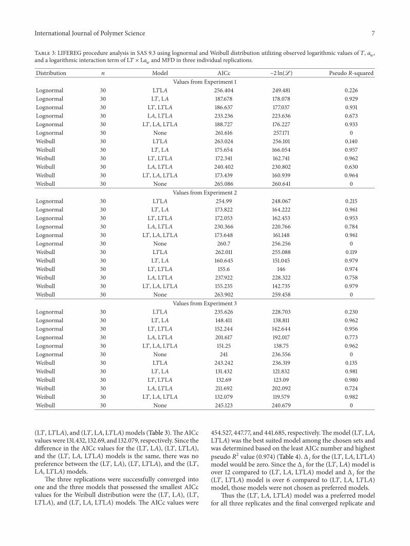
For the first replicate, the three models that possessedthe smallest AICc values for the Weibull distribution werethe (L𝑇, L𝐴), (L𝑇, L𝑇L𝐴), and (L𝑇, L𝐴, L𝑇L𝐴) models(Table 3). The AICc values were 175.654, 172.341, and 173.439,respectively. Since the difference in the AICc values amongthe threemodels was less than 3 there is no preference amongthese models. For the second replicate, the three modelsthat possessed the smallest AICc values for the Weibulldistribution were again the (L𝑇, L𝐴), (L𝑇, L𝑇L𝐴), and (L𝑇,L𝐴, L𝑇L𝐴) models (Table 3). The AICc values were 160.645,155.6, and 155.235, respectively. Since the difference in theAICc values for the (L𝑇, L𝐴) model is over 5 comparedto the other two models, it was not chosen as a preferredmodel. There was no preference between the (L𝑇, L𝑇L𝐴)and the (L𝑇, L𝐴, L𝑇L𝐴) models. For the third replicate,the three models that possessed the smallest AICc valuesfor the Weibull distribution continued to be the (L𝑇, L𝐴),
International Journal of Polymer Science 7
Table 3: LIFEREG procedure analysis in SAS 9.3 using lognormal and Weibull distribution utilizing observed logarithmic values of 𝑇, 𝑎𝑤
,and a logarithmic interaction term of L𝑇 × L𝑎
𝑤
and MFD in three individual replications.
Distribution 𝑛 Model AICc −2 ln(L) Pseudo 𝑅-squaredValues from Experiment 1
Lognormal 30 L𝑇L𝐴 256.404 249.481 0.226Lognormal 30 L𝑇, L𝐴 187.678 178.078 0.929Lognormal 30 L𝑇, L𝑇L𝐴 186.637 177.037 0.931Lognormal 30 L𝐴, L𝑇L𝐴 233.236 223.636 0.673Lognormal 30 L𝑇, L𝐴, L𝑇L𝐴 188.727 176.227 0.933Lognormal 30 None 261.616 257.171 0Weibull 30 L𝑇L𝐴 263.024 256.101 0.140Weibull 30 L𝑇, L𝐴 175.654 166.054 0.957Weibull 30 L𝑇, L𝑇L𝐴 172.341 162.741 0.962Weibull 30 L𝐴, L𝑇L𝐴 240.402 230.802 0.630Weibull 30 L𝑇, L𝐴, L𝑇L𝐴 173.439 160.939 0.964Weibull 30 None 265.086 260.641 0
Values from Experiment 2Lognormal 30 L𝑇L𝐴 254.99 248.067 0.215Lognormal 30 L𝑇, L𝐴 173.822 164.222 0.961Lognormal 30 L𝑇, L𝑇L𝐴 172.053 162.453 0.953Lognormal 30 L𝐴, L𝑇L𝐴 230.366 220.766 0.784Lognormal 30 L𝑇, L𝐴, L𝑇L𝐴 173.648 161.148 0.961Lognormal 30 None 260.7 256.256 0Weibull 30 L𝑇L𝐴 262.011 255.088 0.119Weibull 30 L𝑇, L𝐴 160.645 151.045 0.979Weibull 30 L𝑇, L𝑇L𝐴 155.6 146 0.974Weibull 30 L𝐴, L𝑇L𝐴 237.922 228.322 0.758Weibull 30 L𝑇, L𝐴, L𝑇L𝐴 155.235 142.735 0.979Weibull 30 None 263.902 259.458 0
Values from Experiment 3Lognormal 30 L𝑇L𝐴 235.626 228.703 0.230Lognormal 30 L𝑇, L𝐴 148.411 138.811 0.962Lognormal 30 L𝑇, L𝑇L𝐴 152.244 142.644 0.956Lognormal 30 L𝐴, L𝑇L𝐴 201.617 192.017 0.773Lognormal 30 L𝑇, L𝐴, L𝑇L𝐴 151.25 138.75 0.962Lognormal 30 None 241 236.556 0Weibull 30 L𝑇L𝐴 243.242 236.319 0.135Weibull 30 L𝑇, L𝐴 131.432 121.832 0.981Weibull 30 L𝑇, L𝑇L𝐴 132.69 123.09 0.980Weibull 30 L𝐴, L𝑇L𝐴 211.692 202.092 0.724Weibull 30 L𝑇, L𝐴, L𝑇L𝐴 132.079 119.579 0.982Weibull 30 None 245.123 240.679 0
(L𝑇, L𝑇L𝐴), and (L𝑇, L𝐴, L𝑇L𝐴)models (Table 3).TheAICcvalues were 131.432, 132.69, and 132.079, respectively. Since thedifference in the AICc values for the (L𝑇, L𝐴), (L𝑇, L𝑇L𝐴),and the (L𝑇, L𝐴, L𝑇L𝐴) models is the same, there was nopreference between the (L𝑇, L𝐴), (L𝑇, L𝑇L𝐴), and the (L𝑇,L𝐴, L𝑇L𝐴) models.
The three replications were successfully converged intoone and the three models that possessed the smallest AICcvalues for the Weibull distribution were the (L𝑇, L𝐴), (L𝑇,L𝑇L𝐴), and (L𝑇, L𝐴, L𝑇L𝐴) models. The AICc values were
454.527, 447.77, and 441.685, respectively.Themodel (L𝑇, L𝐴,L𝑇L𝐴) was the best suited model among the chosen sets andwas determined based on the least AICc number and highestpseudo 𝑅2 value (0.974) (Table 4). Δ
𝑖for the (L𝑇, L𝐴, L𝑇L𝐴)
model would be zero. Since the Δ𝑖for the (L𝑇, L𝐴) model is
over 12 compared to (L𝑇, L𝐴, L𝑇L𝐴) model and Δ𝑖for the
(L𝑇, L𝑇L𝐴) model is over 6 compared to (L𝑇, L𝐴, L𝑇L𝐴)model, those models were not chosen as preferred models.
Thus the (L𝑇, L𝐴, L𝑇L𝐴) model was a preferred modelfor all three replicates and the final converged replicate and

8 International Journal of Polymer Science
Table 4: LIFEREG procedure analysis in SAS 9.3 using normal, lognormal, andWeibull distribution utilizing observed logarithmic values of𝑇, 𝑎𝑤
, and a logarithmic interaction term of L𝑇 × L𝑎𝑤
and MFD by converging all three replications together.
Distribution 𝑛 Model AICc −2 ln(L) Pseudo 𝑅-squaredNormal 90 𝑇 795.929 789.65 0.304Normal 90 𝑇𝐴 777.768 771.489 0.431Normal 90 𝐴 794.574 788.295 0.315Normal 90 𝑇, 𝑇𝐴 722.94 714.47 0.698Normal 90 𝑇,𝐴, 𝑇𝐴 641.592 630.877 0.881Normal 90 𝑇,𝐴 664.946 656.476 0.842Normal 90 𝐴, 𝑇𝐴 675.076 666.606 0.823Normal 90 None 826.443 822.305 0Lognormal 90 𝑇 721.653 715.374 0.319Lognormal 90 𝑇𝐴 696.565 690.286 0.485Lognormal 90 𝐴 714.953 708.674 0.368Lognormal 90 𝑇,𝐴 513.004 504.533 0.935Lognormal 90 𝑇,𝐴, 𝑇𝐴 501.898 491.183 0.944Lognormal 90 𝑇, 𝑇𝐴 534.015 525.544 0.918Lognormal 90 𝐴, 𝑇𝐴 503.76 495.289 0.941Lognormal 90 None 754.145 750.007 0Lognormal 90 L𝑇 720.065 713.786 0.331Lognormal 90 L𝑇L𝐴 732.591 726.312 0.231Lognormal 90 L𝐴 714.13 707.851 0.374Lognormal 90 L𝐴, L𝑇L𝐴 649.852 641.381 0.701Lognormal 90 L𝑇, L𝐴, L𝑇L𝐴 491.783 481.069 0.949Lognormal 90 L𝑇, L𝑇L𝐴 494.044 485.574 0.947Lognormal 90 L𝑇, L𝐴 494.084 485.613 0.947Lognormal 90 None 754.145 750.007 0Weibull 90 L𝑇 737.865 731.586 0.278Weibull 90 L𝑇L𝐴 753.965 747.686 0.137Weibull 90 L𝐴 735.125 728.846 0.299Weibull 90 L𝐴, L𝑇L𝐴 672.841 664.371 0.658Weibull 90 LT, LA, LTLA 441.685 430.971 0.974Weibull 90 L𝑇, L𝐴 454.527 446.057 0.969Weibull 90 L𝑇, L𝑇L𝐴 447.77 439.299 0.972Weibull 90 None 765.045 760.907 0
hence it was chosen as the final model. The data from allthree replicates were pooled and each replicate was treatedas a random effect for the location parameter and the finalmaximum likelihood estimates for the scale and locationparameters were determined using the NLMIXED procedurefrom SAS 9.3 (SAS, 2012). The maximum likelihood estimateof the scale parameter is given by
�� = 0.1193. (5)
The maximum likelihood estimate for the locationparameter is given by the following equation:
𝜇 = 6.8216 − 1.5294Log10
(𝑇) − 4.6835Log10
(𝐴)
− 2.1739Log10
(𝑇) × Log10
(𝐴) .(6)
The maximum likelihood estimate of the 100 × 𝑝 per-centile of mold-free days is given by
MFD𝑝= exp (𝜇 + �� ln [− ln (1 − 𝑝)]) . (7)
For example, to estimate the median number of mold-freedays, 𝑝 is 0.5.
The pseudo 𝑅-squared for the model is 0.974 (Table 4).A 3D surface was developed using values obtained from
converged replications (i.e. predicted values of MFDs for anentire set of temperatures (10∘C–40∘C) and water activity(0.80–1.00)) (Figures 6(a) and 6(b)). The observed MFDvalues from all the three replications were then mapped onthe 3D surface of the model derived from all replications.These MFD values appeared on the 3D surface plot with noor very little deviation for the model (Figure 6(b)). It was

International Journal of Polymer Science 9
00.010.020.030.040.050.060.070.080.09
0.10.110.120.130.140.150.160.170.180.19
0.20.210.220.230.240.25
0 5 10 15 20 25 30Number of days
aw = 0.982
aw = 0.973
aw = 0.970
aw = 0.967
aw = 0.964
Moi
sture
abso
rbed
(g)
10∘C samples
25∘C samples
30∘C samples
35∘C samples
40∘C samples
Figure 5: Soy/PE fiber samples stored with potassium sulfate saltsolutions at different temperatures (10∘C, 25∘C, 30∘C, 35∘C, and40∘C). Ultimate moisture absorbed during storage in different rel-ative humidities (0.982, 0.973, 0.970, 0.967, and 0.964, respectively).Each data point denotes a mean value of 6 samples in 3 replications.
concluded that the selectedmodel was effective for predictingMFDs at given temperatures (10∘C–40∘C) and 𝑎
𝑤(0.80–1.00
𝑎𝑤) (Figures 6(a) and 6(b)). Mold growth on biocomposite
films is more likely compared to petroleum-based films dueto the availability of nutrients and moisture. Iganthinathaneet al. (2008) [27] modeled the MFDs to predict the safestorage time and conditions for corn stover reporting that theproduct of storage temperature and storage 𝑎
𝑤was simple
predictor of mold-free days. This only held for the presentstudy for similar 𝑎
𝑤at different temperatures (Table 2).
When a greater number of temperatures and 𝑎𝑤were tested,
predicting the growth of mold was not as straightforward.The current study demonstrates a method to predict moldgrowth and permit the safe storage of soy-PE composites.Thecurrent model predicts over 200 MFDs when stored at 80%RH (0.8 𝑎
𝑤) and 10∘C. Similarmodels could be used to predict
MFDs for the bio-based fibers to create safe storage periodsand conditions for biocomposites.
Films combining protein with synthetic plastics showpotential for production of compostable plastic materi-als. In particular, nonwoven products are replacing manywoven and knit materials because they are low in cost andare lightweight. Degradation of bio-based components bymicroorganisms can render the remaining synthetic polymervulnerable to photodegradation or thermal degradation.While the use of biocomposites can be expanded to producehighly functional, inexpensive material, the need for testingto determine stabilitywill be required due to the degradability
250
200
150
100
50
10
20
30
40 10.95
0.90.85
0.8T
A
MFD
Observed data
220
200
180
160
140
120
100
80
60
40
20
(a)
220
200
180
160
140
120
100
80
60
40
20
250
200
150
100
50
MFD
1 0.95 0.9 0.85 0.8
A
10203040
T
Observed data
(b)
Figure 6: (a) Prediction model for the median number of mold-free days (MFDs) based on temperature (𝑇) and water activity (𝐴)values obtained from the Weibull distribution utilizing observedlogarithmic values of𝑇, 𝑎
𝑤
, and an interaction term of𝑇×𝑎𝑤
of threereplications. Observed mold growth expressed as mold-free days(MFDs) on soy/PE fiber samples from all three replications shownas points on the graph to demonstrate the relationship of observedvalues to the predicted values. (b) A side-view of (a).
of the biological component. The methods and resultsreported here predict the stability bio-based composites andcan be used to develop stable biocomposites in the future.
Conflict of Interests
The authors declare that there is no conflict of interestsregarding the publication of this paper.
Acknowledgment
This research was partially supported by a Grant from theUnited Soybean Board (USB), Grant no. 1480 and 9480“Continuous Calendering-Extrusion Route: Melt-Processing

10 International Journal of Polymer Science
of Ribbon-Fiber Based Nonwovens and Films Derived fromSoy Proteins.”
References
[1] U. G. Kispotta and D. K. Bisoyi, Synthesis and characterizationof bio-compositematerial [Master of Science in Physics], NationalInstitute of Technology, Rourkela. India, 2011.
[2] P. A. Fowler, J. M. Hughes, and R. M. Elias, “Biocomposites:technology, environmental credentials andmarket forces,” Jour-nal of the Science of Food and Agriculture, vol. 86, no. 12, pp.1781–1789, 2006.
[3] K. C. Oksman and C. Clemons, “Mechanical properties andmorphology of impact modified polypropylene-wood flourcomposites,” Journal of Applied Polymer Science, vol. 67, no. 9,pp. 1503–1513, 1998.
[4] G. J. L. Griffin, “Biodegradable fillers in thermoplastic,” in Fillersand Reinforcements for Plastics, R. D. Deanin and N. R. Schott,Eds., vol. 134 of Advances in Chemistry Series, pp. 159–170,American Chemical Society, Washington, DC, USA, 1974.
[5] V. M. Ghorpade and M. A. Hanna, “Physical and mechani-cal properties of soy protein isolate-polyethylene extrudates,”ASAE Paper 93-6533, American Society of Agricultural Engi-neers, Chicago, Ill, USA, 1993.
[6] H. J. Park, J. M. Bunn, R. F. Testin, P. J. Vergano, and D. D. Edie,“Characteristics of corn zein filled polyethylene films,” Tech.Rep. 822, IFT, Chicago, Ill, USA, 1993.
[7] S. Gurram, J. L. Julson, K.Muthukumarrapan, D. D. Stokke, andA.K.Mahapatra, “Application of bio renewable fibers in compo-sites,” in Proceedings of the ASAE/CSAE North Central Intersec-tional Conference, 2002.
[8] Y. S. Zhang, S. Ghasemzadeh, A. M. Kotliar, S. Kumar, S.Presnell, and L. D. Williams, “Fibers from soybean protein andpoly(vinyl alcohol),” Journal of Applied Polymer Science, vol. 71,no. 1, pp. 11–19, 1999.
[9] V. M. Ghorpade, A. Gennadios, M. A. Hanna, and C. L.Weller, “Soy protein isolate/poly(ethylene oxide) films,” CerealChemistry, vol. 72, no. 6, pp. 559–563, 1995.
[10] L. Jong, “Characterization of defatted soy flour and elastomercomposites,” Journal of Applied Polymer Science, vol. 98, no. 1,pp. 353–361, 2005.
[11] J. M. Jay, M. J. Loessner, and D. A. Golden,Modern FoodMicro-biology, Springer, New York, NY, USA, 7th edition, 2005.
[12] W. C. Frazier and D. C. Westhoff, Food Microbiology, McGraw-Hill, New York, NY, USA, 3rd edition, 1988.
[13] A. H. Al-Muhtaseb, W. A. M. McMinn, and T. R. A. Magee,“Water sorption isotherms of starch powders: part 1: math-ematical description of experimental data,” Journal of FoodEngineering, vol. 61, no. 3, pp. 297–307, 2004.
[14] A. H. Al-Muhtaseb, W. A. M. McMinn, and T. R. A. Magee,“Water sorption isotherms of starch powders. Part 2: thermo-dynamic characteristics,” Journal of Food Engineering, vol. 62,no. 2, pp. 135–142, 2004.
[15] M. Erbas, M. F. Ertugay, and M. Certel, “Moisture adsorptionbehaviour of semolina and farina,” Journal of Food Engineering,vol. 69, no. 2, pp. 191–198, 2005.
[16] H. M. Ghodake, T. K. Goswami, and A. Chakraverty, “Moisturesorption isotherms, heat of sorption and vaporization of with-ered leaves, black and green tea,” Journal of Food Engineering,vol. 78, no. 3, pp. 827–835, 2007.
[17] C. Igathinathane, A. R.Womac, S. Sokhansanj, and L. O. Porde-simo, “Sorption equilibriummoisture characteristics of selectedcorn stover components,” Transactions of the American Societyof Agricultural Engineers, vol. 48, no. 4, pp. 1449–1460, 2005.
[18] M. H. Khoshtaghaza, S. Sokhansanj, and B. D. Gossen, “Qualityof Alfalfa cubes during shipping and storage,”Applied Engineer-ing in Agriculture, vol. 15, no. 6, pp. 671–676, 1999.
[19] W. A. M. McMinn, D. J. McKee, and T. R. A. Magee, “Moistureadsorption behaviour of oatmeal biscuit and oat flakes,” Journalof Food Engineering, vol. 79, no. 2, pp. 481–493, 2007.
[20] N. D. Menkov, A. G. Durakova, and A. Krasteva, “Moisturesorption isotherms of common bean flour at several temper-atures,” Electronic Journal of Environmental, Agricultural andFood Chemistry, vol. 4, no. 2, pp. 892–898, 2005.
[21] E. Palou, A. Lopez-Malo, and A. Argaiz, “Effect of temperatureon the moisture sorption isotherms of some cookies and cornsnacks,” Journal of Food Engineering, vol. 31, no. 1, pp. 85–93,1997.
[22] T. Chowdhury and M. Das, “Moisture sorption isotherm andisosteric heat of sorption characteristics of starch based ediblefilms containing antimicrobial preservative,” International FoodResearch Journal, vol. 17, no. 3, pp. 601–614, 2010.
[23] S.-J. Kim and Z. Ustunol, “Solubility and moisture sorptionisotherms of whey-protein-based edible films as influenced bylipid and plasticizer incorporation,” Journal of Agricultural andFood Chemistry, vol. 49, no. 9, pp. 4388–4391, 2001.
[24] S. M. Martelli, G. Moore, S. S. Paes, C. Gandolfo, and J.B. Laurindo, “Influence of plasticizers on the water sorptionisotherms and water vapor permeability of chicken featherkeratin films,” LWT-Food Science and Technology, vol. 39, pp.292–301, 2006.
[25] Y. Wang and G. W. Padua, “Water sorption properties ofextruded Zein films,” Journal of Agricultural and Food Chem-istry, vol. 52, no. 10, pp. 3100–3105, 2004.
[26] R. F. LeBouf, S. A. Schuckers, and A. Rossner, “Preliminaryassessment of a model to predict mold contamination based onmicrobial volatile organic compound profiles,”TheScience of theTotal Environment, vol. 408, no. 17, pp. 3648–3653, 2010.
[27] C. Igathinathane, A. R. Womac, L. O. Pordesimo, and S. Sokh-ansanj, “Mold appearance andmodeling on selected corn stovercomponents duringmoisture sorption,” Bioresource Technology,vol. 99, no. 14, pp. 6365–6371, 2008.
[28] J. Chirife andH.A. Iglesias, “Equations for fittingwater sorptionisotherms of food: part 1—a review,” International Journal ofFood Science & Technology, vol. 13, no. 3, pp. 159–174, 1978.
[29] C. van den Berg and S. Bruin, “Water activity and its estimationin food systems—theoretical aspects,” in Water Activity: Influ-ences on Food Quality, L. B. Rockland and G. F. Stewart, Eds.,pp. 1–61, Academic Press, New York, NY, USA, 1981.
[30] N. Wang and J. G. Brennan, “Moisture sorption isothermcharacteristics of potatoes at four temperatures,” Journal of FoodEngineering, vol. 14, no. 4, pp. 269–287, 1991.
[31] SAS Institute, SAS Software.Version [9.3], SAS Institute, Cary,NC, USA, 2012.
[32] D. R. Heldman, Encyclopedia of Agricultural, Food, and Biologi-cal Engineering, Marcel Dekker, New York, NY, USA, 2003.
[33] G. Saladin, Anatomy and Physiology: The Unity of Form andFunction, McGraw-Hill, New York, NY, USA, 2004.
[34] A. E. Raftery, “Bayesian model selection in social research,”Sociological Methodology, vol. 25, pp. 111–163, 1995.

International Journal of Polymer Science 11
[35] K. P. Burnham and D. R. Anderson, Model Selection and Mul-timodel Inference: A Practical Information-Theoretic Approach,Springer, 2nd edition, 2002.
[36] L. Magee, “R 2 measures based on Wald and likelihood ratiojoint significance tests,” The American Statistician, vol. 44, no.3, pp. 250–253, 1990.

Submit your manuscripts athttp://www.hindawi.com
ScientificaHindawi Publishing Corporationhttp://www.hindawi.com Volume 2014
CorrosionInternational Journal of
Hindawi Publishing Corporationhttp://www.hindawi.com Volume 2014
Polymer ScienceInternational Journal of
Hindawi Publishing Corporationhttp://www.hindawi.com Volume 2014
Hindawi Publishing Corporationhttp://www.hindawi.com Volume 2014
CeramicsJournal of
Hindawi Publishing Corporationhttp://www.hindawi.com Volume 2014
CompositesJournal of
NanoparticlesJournal of
Hindawi Publishing Corporationhttp://www.hindawi.com Volume 2014
Hindawi Publishing Corporationhttp://www.hindawi.com Volume 2014
International Journal of
Biomaterials
Hindawi Publishing Corporationhttp://www.hindawi.com Volume 2014
NanoscienceJournal of
TextilesHindawi Publishing Corporation http://www.hindawi.com Volume 2014
Journal of
NanotechnologyHindawi Publishing Corporationhttp://www.hindawi.com Volume 2014
Journal of
CrystallographyJournal of
Hindawi Publishing Corporationhttp://www.hindawi.com Volume 2014
The Scientific World JournalHindawi Publishing Corporation http://www.hindawi.com Volume 2014
Hindawi Publishing Corporationhttp://www.hindawi.com Volume 2014
CoatingsJournal of
Advances in
Materials Science and EngineeringHindawi Publishing Corporationhttp://www.hindawi.com Volume 2014
Smart Materials Research
Hindawi Publishing Corporationhttp://www.hindawi.com Volume 2014
Hindawi Publishing Corporationhttp://www.hindawi.com Volume 2014
MetallurgyJournal of
Hindawi Publishing Corporationhttp://www.hindawi.com Volume 2014
BioMed Research International
MaterialsJournal of
Hindawi Publishing Corporationhttp://www.hindawi.com Volume 2014
Nano
materials
Hindawi Publishing Corporationhttp://www.hindawi.com Volume 2014
Journal ofNanomaterials