
Research Article Physical Characteristics and Technology...
12
Hindawi Publishing Corporation Journal of Materials Volume 2013, Article ID 696428, 11 pages http://dx.doi.org/10.1155/2013/696428 Research Article Physical Characteristics and Technology of Glass Foam from Waste Cathode Ray Tube Glass G. Mucsi, 1 B. CsYke, 1 M. Kertész, 1 and L. Hoffmann 2 1 Institute of Raw Material Preparation and Environmental Processing, University of Miskolc, Miskolc Egyetemv´ aros 3515, Hungary 2 Geofil Co. Ltd., Alugy´ ari utca 1, Tatab´ anya 2800, Hungary Correspondence should be addressed to G. Mucsi; [email protected] Received 30 November 2012; Revised 17 February 2013; Accepted 18 February 2013 Academic Editor: John W. Gillespie Copyright © 2013 G. Mucsi et al. is is an open access article distributed under the Creative Commons Attribution License, which permits unrestricted use, distribution, and reproduction in any medium, provided the original work is properly cited. is paper deals with the laboratory investigation of cathode-ray-tube- (CRT-) glass-based glass foam, the so-called “Geofil- Bubbles” which can be applied in many fields, mainly in the construction industry (lightweight concrete aggregate, thermal and sound insulation, etc.). In this study, the main process engineering material properties of raw materials, such as particle size distribution, moisture content, density, and specific surface area, are shown. en, the preparation of raw cathode ray tube glass waste is presented including the following steps: crushing, grinding, mixing, heat curing, coating, and sintering. Experiments were carried out to optimize process circumstances. Effects of sintering conditions—such as temperature, residence time, and particle size fraction of green pellet—on the mechanical stability and particle density of glass foam particles were investigated. e mechanical stability (abrasion resistance) was tested by abrasion test in a Deval drum. Furthermore, the cell structure was examined with optical microscopy and SEM. We found that it was possible to produce foam glass (with proper mechanical stability and particle density) from CRT glass. e material characteristics of the final product strongly depend on the sintering conditions. Optimum conditions were determined: particle size fraction was found to be 4–6 mm, temperature 800 ∘ C, and residence time 7.5 min. 1. Introduction e corresponding law regulation which came into force in 2004 divides the electric and electronic equipment into ten categories. ose categories in which cathode ray tube (CRT) is mainly applied (consumer electronics and IT) form a significant fraction (nearly 30%) of the electronic waste. Recycling of the scrap CRT poses a special problem. ere is no public demand for CRT devices any more; accordingly there is no CRT recycling capacity in Europe and there are barely recycling opportunities outside of Europe. Managing this problem is critical from the viewpoint of functional WEEE treatment systems. e volume rate of the waste CRT devices based on the estimations of Bay Zolt´ an Nonprofit Ltd.: in the IT category is about 31% and in the consumer electronic category is about 41% of the total annual amount. ere is no demand for raw material glass with lead content because there is no CRT manufacturer in Europe. Recycling of CRTs is great problem all over Europe as the arising volume of the CRT glass waste is 400000 tons annually and only few practical and economic solutions are found for recycling. ere are two kinds of cathode ray tubes: black and white (or monochrome) and color. ese two types of CRTs are made of different glass [1, 2]. e neck (∼1 wt%) and funnel (∼33 wt%) glass constitute the back part of the CRT (hidden inside the monitor or TV set). e front part, usually known as the panel (∼66 wt%), is made of a barium- strontium glass that is free of lead since 1995 [3, 4] and is very homogeneous and thick. ese three components are usually joined together with a solder glass called frit, which contains 85 wt% lead. e neck glass of cathode-ray tube glass is a lead-rich silicate glass containing up to 40 wt% PbO, which envelopes the electron gun. e lead content of funnel glass is lower than that of neck glass (∼20–25 wt% of PbO). e addition of lead to this glass is essential for absorbing the UV and X-ray radiation produced by the electron gun in CRTs. In the panel glass of color CRTs, however, barium and strontium are used instead of lead because this glass needs to be colorless [5, 6].
Transcript of Research Article Physical Characteristics and Technology...

Hindawi Publishing CorporationJournal of MaterialsVolume 2013, Article ID 696428, 11 pageshttp://dx.doi.org/10.1155/2013/696428
Research ArticlePhysical Characteristics and Technology of Glass Foam fromWaste Cathode Ray Tube Glass
G. Mucsi,1 B. CsYke,1 M. Kertész,1 and L. Hoffmann2
1 Institute of Raw Material Preparation and Environmental Processing, University of Miskolc, Miskolc Egyetemvaros 3515, Hungary2 Geofil Co. Ltd., Alugyari utca 1, Tatabanya 2800, Hungary
Correspondence should be addressed to G. Mucsi; [email protected]
Received 30 November 2012; Revised 17 February 2013; Accepted 18 February 2013
Academic Editor: John W. Gillespie
Copyright © 2013 G. Mucsi et al.This is an open access article distributed under the Creative Commons Attribution License, whichpermits unrestricted use, distribution, and reproduction in any medium, provided the original work is properly cited.
This paper deals with the laboratory investigation of cathode-ray-tube- (CRT-) glass-based glass foam, the so-called “Geofil-Bubbles” which can be applied in many fields, mainly in the construction industry (lightweight concrete aggregate, thermal andsound insulation, etc.). In this study, the main process engineering material properties of raw materials, such as particle sizedistribution, moisture content, density, and specific surface area, are shown. Then, the preparation of raw cathode ray tube glasswaste is presented including the following steps: crushing, grinding, mixing, heat curing, coating, and sintering. Experiments werecarried out to optimize process circumstances. Effects of sintering conditions—such as temperature, residence time, and particle sizefraction of green pellet—on the mechanical stability and particle density of glass foam particles were investigated. The mechanicalstability (abrasion resistance) was tested by abrasion test in aDeval drum. Furthermore, the cell structure was examinedwith opticalmicroscopy and SEM. We found that it was possible to produce foam glass (with proper mechanical stability and particle density)from CRT glass.Thematerial characteristics of the final product strongly depend on the sintering conditions. Optimum conditionswere determined: particle size fraction was found to be 4–6mm, temperature 800∘C, and residence time 7.5min.
1. Introduction
The corresponding law regulation which came into forcein 2004 divides the electric and electronic equipment intoten categories. Those categories in which cathode ray tube(CRT) is mainly applied (consumer electronics and IT) forma significant fraction (nearly 30%) of the electronic waste.
Recycling of the scrapCRTposes a special problem.Thereis no public demand for CRT devices any more; accordinglythere is no CRT recycling capacity in Europe and there arebarely recycling opportunities outside of Europe. Managingthis problem is critical from the viewpoint of functionalWEEE treatment systems. The volume rate of the waste CRTdevices based on the estimations of Bay Zoltan NonprofitLtd.: in the IT category is about 31% and in the consumerelectronic category is about 41% of the total annual amount.
There is no demand for raw material glass with leadcontent because there is no CRT manufacturer in Europe.Recycling of CRTs is great problem all over Europe as thearising volume of theCRTglasswaste is 400000 tons annually
and only few practical and economic solutions are found forrecycling.
There are two kinds of cathode ray tubes: black andwhite (or monochrome) and color. These two types of CRTsare made of different glass [1, 2]. The neck (∼1 wt%) andfunnel (∼33wt%) glass constitute the back part of the CRT(hidden inside the monitor or TV set). The front part,usually known as the panel (∼66wt%), is made of a barium-strontium glass that is free of lead since 1995 [3, 4] and is veryhomogeneous and thick.These three components are usuallyjoined together with a solder glass called frit, which contains85wt% lead. The neck glass of cathode-ray tube glass is alead-rich silicate glass containing up to 40wt% PbO, whichenvelopes the electron gun. The lead content of funnel glassis lower than that of neck glass (∼20–25wt% of PbO). Theaddition of lead to this glass is essential for absorbing the UVand X-ray radiation produced by the electron gun in CRTs. Inthe panel glass of color CRTs, however, barium and strontiumare used instead of lead because this glass needs to be colorless[5, 6].

2 Journal of Materials
Mear et al. [5, 6] determined the chemical composition,densities, coefficient of thermal expansion, and the glass tran-sition temperature of waste cathode ray tube glass originatedfrom Asian or South-Asian manufacturers (including Japan,Taiwan, and Korea). They found that color CRTs are madewith two different glass formulations, one for the panel andone for the funnel, in contrast to black andwhite CRTs, whichuse only one formulation.
There are several technologies for the utilization of CRTglass in the literature. Some of them are shown below. Forexample, Chen et al. [7] investigated the recovery of metalliclead from the funnel glass and the preparation of foam glass.In the pyrovacuumprocess, lead in the funnel glass was firstlydetached and changed to PbO, then reduced and evaporated,and was recovered in the form of pure metal with a purityof 99.3%. The maximum lead removal rate reached 98.6%when the temperature, pressure, carbon adding amount, andholding time were 1000∘C, 1000 Pa, 9%, and 4 h, respectively.The produced porous glass was environmentally acceptablefor construction applications.
Envirocycle (a US company) developed a process [8] torecycle all glasses contained in CRTs; this process includescleaning and sorting of the glass. The product obtained isused for the manufacture of new CRT glass. Some industrieshave used pulverized glass from CRTs in smelting processesas slagging material instead of sand or slag.
Mear et al. [5, 6] examined the effects on foam glassmicrostructures by varying the elaboration parameters, reac-tion time, temperature, and composition with scanningelectron microscopy. Foam glass was prepared using variousconcentrations of SiC or TiN as the reducing agent for varioustemperatures (750, 850, and 950∘C) and reaction times (30,60, and 90min). They demonstrated that increases in thethree synthesis parameters strongly affect themicrostructuresof the foam glasses. Increases in cell diameter lead to largereductions in mechanical resistance. Further, the reductionof lead oxide content in these glasses also increases, as shownby the increase inmetal lead formation in the formof droplets(bubbles) on the cell surface.
Kim et al. [9] developed a method producing a concretecomposite crosslinked with minute amounts of biopolymersand a cross-linking agent. Commercially available microbialbiopolymers of xanthan gum and guar gum were used.This CRT—biopolymer—concrete (CBC) composite showedhigher compressive strength than the standard concrete anda considerable decrease in lead leachability (good encap-sulation of CRT wastes) as measured by standard USEPAmethods.
There are technologies for extracting metal oxides fromglass. One way is smelting to reduce the metal oxides tometal by melting the glass waste in reducing conditionsusing reactants (carbon, aluminium). Another way is theelectrolytic separation by applying a voltage across a moltenbath of glass [10]. Furthermore, the CRT glass can be utilizedas a substitute for sand in the smelting process, the generatedslag can then be used as road aggregate. Additionally, it can beused in the ceramics and building products industry (bricksand tiles or as a flux). To be used in this way, the glass mustbe free from contamination and ground to fine size.
According to Seo et al. [11], possible application technolo-gies of CRT panel waste are cement brick, clay brick, and glasswool. Also, application technologies of funnel are glazing andlead smelting. As results of cement brick and clay brick in lab-scale tests, the entire samples satisfied the Korean Standard.
A pellet product under the name “Geofil-Bubbles” [12]from industrial waste material of high glass content ismanufactured by recycling technology (Hungarian patent).The waste glass materials may have organic and inorganicimpurities. Waste materials of high glass content are groundto appropriate particle fineness. The pelletization process iscarried out by adding melting point reducer and viscositymodifying agents. The green pellet is then heat cured andcoated to decrease its water absorbing capability. Sintering iscarried out in a rotary furnace. The product is a lightweightartificial gravel with a diameter of 1 to 25mm having pri-marily thermal and sound insulating properties with goodbonding capability if embedded in gypsum, cement, or resinmatrix.
Jozsa and Nemes [13] studied different types of “Geofil-Bubbles” manufactured of waste glass using recycling tech-nology which were tested at the Department of Construc-tion Materials and Engineering Geology, Budapest Univer-sity of Technology and Economics as lightweight aggregatefor concrete (LWAC). This new material is alkali resistant(according to DAfStb 1986). Similar compressive strengthscan be reached by LWACas in case of normal-weight concrete(NWC). Even higher strength can be reached by additionalsilica fume or cement or by lower water/cement ratio.Admixtures are required to have appropriate workability. 2-day compressive strengths of LWAC were 75% of that of 28days.
In the previous patent and study [12, 13], the applicationof theGeofil bubbles in the construction industry was investi-gated. However, the present paper shows the results regardinglaboratory scale preparation of the above-mentioned productfrom process engineering point of view. The general aim ofthis research is to develop the “Geofil-Bubbles” technologyfor CRT-glass-based foam for industrial applications, mainlyconstruction industrial use. The goal of this paper is toshow a brief overview of cathode ray tube glass processingpossibilities and to demonstrate the experimental resultscarried out at the University of Miskolc in order to optimizethe pelleting and the sintering processes.
2. Material Properties
Firstly, the received dismantled CRTwaste of black and white(monochrome) and color TVs were prepared for laboratorytests. The waste glass was first crushed with a jaw crusherand then milled by a rolls mill. Physical material propertieswere measured in the waste glass and other raw materials(bentonite, limestone, dolomite, and alumina), for example,particle size distribution, density, moisture content, andgrindability (Hardgrove Grindability Index and calculatedBond-Work Index).
The particle size distribution of the ground material wasmeasured by HORIBA LA-950V2 laser diffraction particle

Journal of Materials 3
Table 1: Chemical composition of the raw materials (additives).
Name SiO2 TiO2 Al2O3 FeO Fe2O3 MnO CaO MgO Na2O K2O −H2O +H2O CO2 P2O5 SO3 BaO SrO%
Limestone 2.01 <0.02 0.465 <0.02 0.202 0.009 54.9 0.523 0.046 <0.2 0.05 0.05 41.6 <0.15 <0.15 <0.005 0.037Dolomite 0.326 <0.02 0.151 <0.02 0.040 <0.003 30.2 21.9 0.070 <0.2 <0.01 0.10 46.7 <0.15 <0.15 <0.005 0.011Na-bentonite(Egyhazaskeszo) 44.1 2.02 15.6 0.086 9.11 0.081 1.92 2.03 3.34 0.607 9.43 7.89 2.42 0.277 <0.15 0.050 0.017
Na-bentonite(Petervasara) 62.6 0.267 12.7 0.131 2.33 0.056 1.61 0.764 1.06 1.44 7.75 6.78 0.563 <0.15 <0.15 0.070 0.014
Ca-bentonite 44.1 2.09 16.1 0.114 9.32 0.043 1.83 2.15 0.439 0.709 8.04 10.2 0.492 0.333 <0.15 0.045 0.017Corundum 0.128 <0.02 99.3 <0.02 0.053 0.004 0.033 <0.15 0.264 <0.2 0.03 0.02 <0.02 <0.15 <0.15 0.006 0.002
Table 2: Phase composition of the raw materials (additives).
Sample Corundum Na-bentonite (P) Ca-bentonite Na-bentonite (E) Limestone DolomiteMontmorillonite 47 39 73Illit-montmorillonite 14Illite 7 18Kaolonite 3Quartz 6 5 6 2Plagioclase 5Calcite 3 7 4 96Dolomite 2 100Anatase 3Corundum 98Diaoyudaoit 2Clinoptilolite 2Cristobalit 21Amorphous 9 17 11
size analyzer in wet mode using distilled water as dispersingmedia and sodium-pyrophosphate as dispersing agent apply-ing the Mie theory as evaluation method. The density wasdetermined by pycnometer method using alcohol as media.Moisture content was measured in drying oven at 105∘C untilconstant mass. The drying time required to achieve constantmass varied depending on the type of the material, thatis, bentonite, limestone, and corundum. In most cases, anovernight (12–16 h) drying period was sufficient.
The materials used were as follows: foaming agents weredolomite and limestone, pelleting agents were Na-bentonitesand Ca-bentonite, additionally Al
2O3was used to avoid
aggregation of melted particles.The chemical (oxidic) and phase composition of the addi-
tives were determined. Oxidic composition was measured byLiBO2extraction. The results can be seen in Table 1.
Additionally, the mineral composition of the materialswas determined by Philips PW 1730XRD apparatus (Table 2).Corundum, limestone, and dolomite have relatively homoge-neous mineral composition. However, in the three bentonitesamples montmorillonite, illite, kaolinite, quartz, plagioclase,calcite, clinoptilolite, and cristobalite were detected as mainminerals. Furthermore, the amorphous content of bentonitesamples was 9, 11, and 17%.
For the characterization of the grindability of mineralsdifferent grindability indices—BondWork Index (𝑊
𝑖), Hard-
grove Grindability Index (HGI), or Zeisel-Specific Grind-ability (𝑊
𝑡)—are used. Generally, Bond Work Index for mill
dimensioning and controlling is measured by grinding thefeed material of <3.36mm particle size under standardizedconditions in a so-called Bond mill (𝐷 × 𝐿 = 305mm ×305mm). Bond method simulates closed-circuit grindingwhich is carried out in sections until the establishment ofequilibrium. From the evaluation of laboratory and industrialexperiments, the work index can be determined as follows[14]:
𝑊
𝑖𝐵=
4.9
𝑥
0.23
max𝐺0.82
(1/√𝑥
80− 1/√𝑋
80)
, (1)
where𝑊𝑖𝐵
= Bond laboratory ball work index (kWh/t); 𝑥max= max. particle size of the product (<106𝜇m) in 𝜇m; 𝐺 = netgrams of sieve undersize per mill revolution (g/rev); 𝑥
80=
80% passing size of the product in 𝜇m; 𝑋80
= 80% passingsize of the feed in 𝜇m.

4 Journal of Materials
Table 3: Density and moisture content of the raw materials.
Sample Limestone Al2O3 Dolo-mite Na-bentonite 1 Na-bentonite 2 Ca-bentonite GlassDensity, kg/m3 2719.6 3916.2 2610.8 2192.4 2291.7 2340.5 2819.9Moisture content, % 0.19 0.39 0.34 7.30 8.16 5.72 0.52
Table 4: Grindability indices of the CRT glass parts.
Monoch. front Monoch. funnel Color front Color funnelHGI 48.83 50.28 46.54 51.81Bond- work index, kWh/t 17.95 17.51 18.65 17.08
The grindability was determined using the conventionalHardgrove test method where the HGI is calculated by thefollowing formula:
HGI = 13 + 6.93𝑚74, (2)
where HGI is the Hardgrove Grindability Index, and 𝑚74
isthe mass of product finer 74𝜇m in g.
Using the HGI value the Bond Work Index can becalculated by the following equation:
𝑊
𝐻
𝑖𝐵
=
468
HGI0.82. (3)
The particle size distributionwasmeasured by dry sievingand Fritsch Analysette 22 type laser size analyzer; the curvesare given in Figure 1.
The raw material properties are found in Tables 3 and 4.From these data, it can be established that moisture contentwas very low (<1%) except of the bentonite samples (5.72–8.16%). Furthermore, the grindability of the front glass was abit higher than that of the funnel glass in both glass types:monochrome and color. It means that previous ones needmore specific grinding energy than latter ones to reach thesame material fineness. The grindability has an importantgoal froma technological point of viewwhenprocessing plantis designed.
3. Experimental
In the research work, we focused on the product so called“Geofil-Bubbles.” As it was mentioned before, this is aspherical shape glass foam which can be used as heat andsound insulatingmaterial (high porosity). One key step of thetechnology is the pelletization of the ground raw materials.For this purpose, laboratory experiments were performed todetermine the optimal conditions for producing pellets withgoodmechanical stability. Before this step, the raw glass wastewas ground in a laboratory ball mill to reach the appropriatefineness, and then additives—bentonite and limestone—werefed into the mill to homogenise them (intergrinding).
The green pellets were manufactured with a pelletingplate in batch mode. After preparing the green pellets, theywere dried in a drying cabinet at 105∘C for 2 hours. Themechanical stability (resistance of pellets to degradation byabrasion) of the dried pellets was tested with a conventionalDeval drum (Ø210 × 340mm) apparatus. Generally, the
Deval Attrition Test Machine is used for the determinationof resistance of aggregates to wear by abrasion. It consists ofa hollow cylinder closed at one end and provided with tightfitting covers at the either end. The cylinder is mounted on ashaft at an angle of 30 degrees with the axis of rotation of theshaft. The shaft rotates at 30–33 r.p.m. through a reductiongear operated by a motor and is provided with a revolutioncounter.
In this test series, the standardmethodwasmodified to beable for fast test. A given amount (25 gramms) of pellet wasfed into the Deval drum, the residence time was 10min (300revolutions), and then the particles were sieved to determinethe mass fraction of the material finer than 1mm.The feed ofthe test was the fraction of green pellets coarser than 2.5mm.In this way, the mass fracion of particles finer than 1mm—produced in the drum—characterizes the abrasion loss (rateof abrasion) of pellets in dry circumstances.
The abrasion was calculated using following formula:
Δ𝑚abr =𝑚fine𝑚feed100 [%] , (4)
where Δ𝑚abr is the rate of abrasion in %, 𝑚fine is the weightof material <1mm in g, and𝑚feed is the feed weight of Devaltest (25 g).
The variable parameters for the pelleting experimentswere as follows: (1) concentration of Na bentonite, (2) watercontent, and (3) revolution of the pelleting plate.
The variable parameters of sintering experiments were (1)pellet size, (2) sintering temperature, and (3) residence time.In order to monitor the behaviour of particles with differentsize during the sintering process, the previously prepareddried pellets were separated into size fractions, that is, 2–4mm, 4–6mm, and 6–8mm.After sieving, each size fractionof the material was sintered in a furnace at 600, 650, 700,750, 800, 850, and 900∘C. Additionally, the residence timewas decided to be 5, 7.5, and 10min. After sintering the glassfoam particles were cooled down at room temperature andthe abrasion loss (same way as described before) and particledensity was determined. For monitoring the foam structure,opticalmicroscopymeasurementswere performedwith ZeissImager.M2m apparatus.
4. Results
4.1. Pelleting Results. In the first experimental series, theeffect of the concentration of bentonite was investigated in

Journal of Materials 5
1 10 100
1
0.8
0.6
0.4
0.2
0
𝐹(𝑥)
Particle size (𝜇m)
AluminaCa bentoniteDolomiteLimestone
Na bentonite 1Na bentonite 2Ground CRT
Figure 1: Particle size distribution of raw materials (treated).
the dosage of 0, 2.5, 5, 7.5, and 10% for the mass of glass. Thewater content and the revolution of the plate were constant,20% and 40% of the critical speed, respectively.
The mechanical stability of the pellets can be seen inFigure 2. The most significant difference (15%) was foundbetween 0 and 2.5m/m% bentonite content; after this pointa slight decrease can be found in the rate of abrasion.
In the second step, the effect of the speed of the plate wasexamined with 40, 50, 60, and 70% of the critical speed. Itwas observed that increasing the pelleting plate’s speed causedno evident changes in the mass fraction of fines. However,the shape of the particles changed significantly, that is, morespherical shapes were achieved at higher speeds [15].
In the third series, the effect of the water content wasstudiedwith 17.5, 20, and 22.5m/m%water dosage. Accordingto our results, the optimal water dosage was 20m/m%.Pellets with lower water content (17.5%) became weak dueto the insufficient capillary forces. In contrast to this, thehigher water content resulted better throughput (kg/h) ofthe valuable size fraction. At the same time, the particleswere generated with deformed shape and coarser diameter,furthermore, the material loss increased due to the stickingof the powder to the wall of the apparatus [15].
Based on our study, it can be concluded that using theabove presented raw materials under the suitable condi-tions, pellets with appropriate mechanical stability can beproduced. Optimal pelleting parameters were determined:bentonite concentration was found to be 2.5–7.5m/m%, platespeed was 60% of the critical speed, andwater content (whichwas the most sensitive parameter) was 20m/m%.
4.2. Results of Systematic Sintering Experiments
4.2.1. Particle Density. At the temperature at which the glassprimary particles become soft enough to cohere, the agent
0 2 4 6 8 100
20
40
60
80
100
Bentonite content (%)
Rate
of a
bras
ion
(%)
Figure 2: Mechanical stability of pellets as function of bentoniteconcentration.
(calcite) gives off a gas (CO2) that is entrapped in the glass and
forms the closed-cell structure that remains after cooling.Themain effect of CO
2gas generation in the glass pellet during
sintering is the increase of porosity and parallelly the decreaseof particle density.
The foaming of CRT glasses by CaCO3thermal decom-
position does not depend on oxidation/reduction processes,which could cause the precipitation of metallic colloids byreduction of easily reducible oxides like PbO. Moreover, therelatively low temperature required (CRT glasses have a lowsoftening point) prevents the volatilization of the PbO [16].
The change of particle density is described in the fol-lowing part as function of residence time and temperaturedepending on pellet size. The particle density of the threedifferent size fractions is plotted as function of temperaturein Figure 3.
The initial particle density of dried green pellets wasfound to be
(i) fraction 2–4mm: 𝜌𝑝= 2226.72 kg/m3;
(ii) fraction 4–6mm: 𝜌𝑝= 1905.54 kg/m3;
(iii) fraction 6–8mm: 𝜌𝑝= 2054.17 kg/m3.
The sintering temperature has great influence on theparticle density of the product. However, Figure 3 showsthat the temperature has no significant effect on the densityof the pellet at any size faction in the temperature rangefrom 600 to 750∘C independently from the residence time.Fluctuation of particle density can be detected in a widerange from 1700 kg/m3 up to 2500 kg/m3 (instable section).Therefore, these temperatures are insufficient for producingfoam structure. However, slight increase was found in theabove temperature interval if average values are taken intoaccount. Probably it can be explained by the phenomenon

6 Journal of Materials
600 700 800 9000
500
1000
1500
2000
2500
Part
icle
den
sity
(kg/
m3)
Sintering temperature (∘C)5min, 5min, 5min, 7.5min, 7.5min,
7.5min,10min, 10min, 10min,
2–4mm4–6mm6–8mm2–4mm4–6mm
6–8mm2–4mm4–6mm6–8mm
Figure 3: Influence of temperature on particle density.
that glass melting starting prior to carbon dioxide release.In this way, the density starts to increase and when thegas generation starting (about 800∘C) the density decreasedsuddenly.
Contrary to the above written phenomena, a significantdecrease of particle density was observed at 800∘C at 7.5 and10-minute time, this decrease appears at 850 and 900∘C evenat 5min residence time.
The reason behind density decrease can be explainedwiththe phenomenon of CO
2generation due to the calcination
of the limestone (foaming agent) at higher than 750∘C. Thegas expands, which results in a cellular structure. Parallelly,the glass reaches its softening point and becomes meltedavoiding the escape of gas from the particle resulting ina porous structure, foam-like particle with high strength.Another effect of the sintering process that through CO
2gas
forms cells, the diameter of the particle becomes at least twotimes higher.
Glass viscosity, the foaming temperature, and residencetime are strongly related.The optimum foaming temperaturemust be selected by considering, on the one hand, the max-imum foam stability, which is controlled by viscosity, and,on the other hand, the internal cell structure, characterizedby homogeneous and regular shape and size of the poresand by the minimum thickness of their separating walls[17]. If the foaming temperature is high, the melt viscosityis too low, and controlling the structure becomes difficultbecause bubbles rise to the top of the mold (as in fining ofglass). On the contrary, if the temperature is low, the glassviscosity is high, and gas expansion is difficult and littleincrease in volume occurs. In this case, the formation of the
0 1 2 3 4 5 6 7 8 9 1020
40
60
80
100
120
140
mm, 600 ∘Cmm, 650∘Cmm, 700∘Cmm, 750∘C
800 ∘Cmm, 850∘Cmm, 900 ∘C
Time (min)
Relat
ive d
ensit
y (%
)
2–42–42–42–4
2–4mm,2–42–4
Figure 4: Change of relative density as function of residence timein case of size fraction 2–4mm.
separating walls does not go to completion, and residual openporosity results, so that water absorption of the glass foam inservice increases. During the period of gas release, the densitycontinuously decreases down to aminimumvalue.When thisstage finishes, a gradual process of destruction and collapseof the foam by coalescence of the pores begins. Thus, thesurface energy of the system is decreased by the reduction ofthe specific surface area of the walls of the cells. This processleads to a new increase in density [18]. Hence, it is necessaryto calculate precisely the time of heat treatment and to removethe glass foam from the hot zone prior to the beginning of thecoalescence process.
According to the literature, the most convenient viscosityrange for optimizing the foaming process for developmentof maximum of porosity and minimum apparent (particle)density is 105 to 103 Pa⋅s [16].
To compare the effect of residence time on the densityof particles for every size fractions, relative density wascalculated for each case. It was determined by the ratio of finaldensity and initial value. These curves can be seen in Figures4–6. The most substantial density decrease was reached at900∘C (5min), where 34, 37, and 27% of the original densitywas reached at 2–4mm, 4–6mm, and 6–8mm, respectively.However, further increase of time at this temperature resultsin higher density, thematerial starts to bemore compact withless porous structure because the gas can escape from theparticle. It can be explained by the fact that the viscosity ofthe melted glass probably diminishes at 900∘C, and there isenough time for this phenomenon to be taking place.
In the interval of 600–750∘C sintering temperature, onlyslight decrease (maximum 20%) was achieved even at 7.5

Journal of Materials 7
0 1 2 3 4 5 6 7 8 9 1020
40
60
80
100
120
140
Time (min)
Relat
ive d
ensit
y (%
)
mm, 600 ∘Cmm, 650∘Cmm, 700∘Cmm, 750∘C
800 ∘Cmm, 850∘Cmm, 900 ∘C
4–64–64–64–6
4–6mm,4–64–6
Figure 5: Change of relative density as function of residence time incase of size fraction 4–6mm.
and 10min residence time in the 2–4mm fraction (Figure 4).Only exception was at 750∘C where the particle density firstincreased by 4% at 5min then started to drop down. Contraryto this, the relative density of the 4–6mm fraction increasedin the above-mentioned temperature range (Figure 5). In thecoarser pellets, heat cannot be transferred into the innerpart of the particles; therefore, calcination of foaming agent(limestone) did not take place appropriately. Only the glassmelted near to the surface resulting in higher density (morecompact structure).
The relative density diminished suddenly at 800∘C from92% down to 39% (Figure 4) when time increased from 5minto 7.5; then the parameter was constant. Similar effect wasobserved in case of the other two size fractions (Figures 5 and6).Therefore, it can be established that 800∘C is a critical value(limit temperature) between porous and compact structures.
In the temperature range of 600–750∘C, a similar effectwas found in all the three sizes; the relative density wasfluctuating, but the rate of fluctuation was diverse. Thisdifference range was (−10%)–(+10%), (−5%)–(+25%), and(−20%)–(+5%) in the 6–8mm, 4–6mm, and 2–4mm frac-tion, respectively.
Based on the results shown in Figures 4–6, sharp densitydecrease happens at 800∘C; this is represented by a steepcurve section. However, gradual decrease can be seen at850∘C in all the three size fractions. It can be concluded thatthere is diversity in the trends in the lower temperature range(600–750∘C) and similarities are in the upper temperaturezone (800–900∘C) in the investigated size fractions.
From Figures 3–6, it can be established that the idealtemperature and residence time from the viewpoint of density
0 1 2 3 4 5 6 7 8 9 1020
40
60
80
100
120
140
Time (min)
Relat
ive d
ensit
y (%
)
mm, 600 ∘Cmm, 650∘Cmm, 700∘Cmm, 750∘C
800 ∘Cmm, 850∘Cmm, 900 ∘C
6–86–86–86–8
6–8mm,6–86–8
Figure 6: Change of relative density as function of residence timein case of size fraction 6–8mm.
decrease is 900∘C and 5min, respectively, based on ourexperience, when relative density decreased dramatically by∼70%.
The viscosity and the surface tension of a silicate glassmelt can be altered by the addition of quick lime, whichis the residue from decomposition of the calcium. Themodification of the viscosity of the glass melt is dependenton the miscibility of the oxide system.Therefore, it is feasiblethat the addition of small amounts (1–3wt %) of quick lime tothe silicate glass melt will give rise to a small degree of phaseseparation which consequently results in the formation of aglass melt with high surface tension, but low viscosity, thuspermitting a greater volume expansion of the molten masscarbonate [16].
Contrary to the results of Mear et al. [5, 6] where 30,60, and 90min reaction time was used, we investigated theeffect of shorter sintering time (5; 7.5, and 10min) to the foamproperties resulted in an applicable foam structure. However,the sintering temperature range was similar.
4.2.2. Abrasion Loss. From application point of view, themechanical stability of final product is of great importance.To investigate the abrasion resistance (rate of abrasion) ofthe foam, modified Deval tests were carried out as describedpreviously. Since the initial pellet size does not reach thestandard size fraction (10–14mm), contrary to that themeasurement was carried out using the manufactured pellets(2–4mm, 4–6mm, and 6–8mm) using 10min residence timeand then the product was sieved at 1.6mm sieve aperture size,the evaluation used the mass of material finer 1.6mm. The

8 Journal of Materials
5 6 7 8 9 100
2
4
6
8
mm, 800 ∘Cmm, 850∘Cmm, 900∘Cmm, 800∘Cmm, 850 ∘C
mm, 900∘Cmm, 800 ∘Cmm, 850 ∘Cmm, 900∘C
Sintering time (min)
Rate
of a
bras
ion
(%)
2–42–42–4
4–6
4–6
4–6
6–86–86–8
Figure 7: Abrasion of glass foam particles as function of sinteringtime.
Table 5: Inner cell size of glass foammanufactured at 900∘C, 7.5min.
1 2 3Size range of pellet, mm 2–4 4–6 6–8Size interval of inner cells, 𝜇m 100–250 150–400 200–900
results can be seen in Figure 7, where particles with real foamstructure were tested, manufactured at 800, 850, and 900∘C.
It can be observed from Figure 7 that the rate of abrasionis considerably different depending on the particle sizeinterval. The lowest abrasion rate (0.2–1.3%) was found atthe size fraction 2–4mm. Higher fluctuation was observedin the other two fractions: 0.8–3.5% and 2.2–7.5% at 4–6mmand 6–8mm, respectively. The relationship between particlesize and abrasion resistance was revealed: the higher the glassfoam particle size, the lower its resistance to abrasion stress(mechanical stability).
The effect of foaming temperature can be seen in Figure 7,the higher the temperature the higher the abrasion loss in allthree particle size fractions of pellets at 5 and 7.5min sinteringtime. However, this order changed at longer residence time(10min); that is, the abrasion loss of foam prepared at 900∘Cwill be lower than that of 800 and 850∘C in size fractions 2–4mm and 4–6mm.
Mostly at the 7.5min residence time, the rate of abrasionincreased compared with results obtained at 5min indepen-dently from size fraction and temperature. A further increaseof residence time (10min) resulted in lower rate of abrasionand higher mechanical stability again at 900∘C.
Based on the abrasion test result,s the 2–4mm and 4–6mm are the suggested size fraction for manufacture of foamglass particles (Geofil-Bubbles).
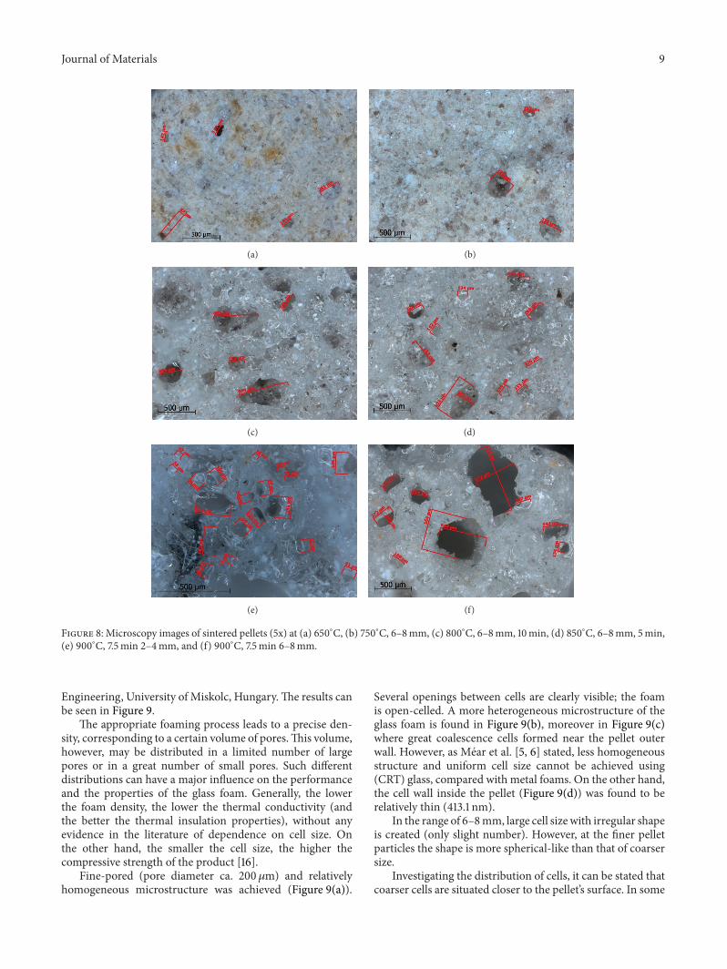
4.2.3.Microstructure of Foam. Thegenerated gas created cellsin the particles which plays a role in volume increase and inmass decrease at 800, 850, and 900∘C. In order to investigatethe size, shape and distribution of cells measurements werecarried out with optical microscopy using Zeiss Imager.M2m(5x).
In the case of the experiment performed at 600∘C,a relatively homogeneous structure was prepared withoutporous structure, since the calcinations of CaCO
3did not
start at that temperature. Contrary to this result, some cellsare generated at 650∘C. However, nonmelted primary glassparticles can be seen well in Figure 8(a).
Comparing the three size fractions, no significant differ-ence in the size and number of cells can be detected in themicroscopy images at 650∘C. The sizes of cells are generallyin the range of 100–200𝜇m.
At 750∘C a few number of bigger cells are detected;their size depends on the original size of pellet particles(Figure 8(b)). At smaller size, the size of cells does notexceed 200 𝜇m; however, 300 𝜇mcells are generated at higherparticle size. Micron size primary glass particles still can beseen.
In Figure 8(c), the microscopy image of pellets sinteredat 800∘C, 6–8mm for 10min is shown. The image representswell the structure generated at that temperature.Thediameterand distribution of inner cells are higher than those oflower temperatures. Their size is in the range of 100–700𝜇mdepending on the pellet’s size. Characteristic cell size is indirect proportional to the diameter of pellets. Due to theintensive melting of glass at 800∘C, the color of cooledsintered pellets is getting glassy like (molten glass phase),instead of the initial primary particles. Micron size glassparticles cannot be seen at 800∘C; the homogeneous meltedglass structure will be typical of the product mainly.
It can be observed that the color of pellets sintered atlower temperatures is darker, the number of cells is insignif-icant, and the diameter is smaller than that of produced athigher temperatures, especially at 850∘C. The considerabledecrease of particle density established previously is sup-ported by the microscopic images (Figure 8(d)).
It can be established that the increase of temperatureand residence time results in higher number of cells in allthree size ranges of pellets; their distribution was identical.The change of color and transparency shows similarities. Thedifference can be recognized only in the size of cells. Thesmaller the glass foam pellet’s size, the smaller the average cellsize (Table 5). Cell size generated at 900∘C in different pelletsize fraction can be seen in Figures 8(e) and 8(f).
Scanning electron microscopy (SEM) was used to takeimages on the samples for the visual observation of cell sizeand morphology. The micrographs were taken with a ZeissEVO MA 10 Scanning Electron Microscope with 25 and2000 magnification at the Faculty of Materials Science and
Journal of Materials 9
(a) (b)
(c) (d)
(e) (f)
Figure 8: Microscopy images of sintered pellets (5x) at (a) 650∘C, (b) 750∘C, 6–8mm, (c) 800∘C, 6–8mm, 10min, (d) 850∘C, 6–8mm, 5min,(e) 900∘C, 7.5min 2–4mm, and (f) 900∘C, 7.5min 6–8mm.
Engineering, University of Miskolc, Hungary.The results canbe seen in Figure 9.
The appropriate foaming process leads to a precise den-sity, corresponding to a certain volume of pores.This volume,however, may be distributed in a limited number of largepores or in a great number of small pores. Such differentdistributions can have a major influence on the performanceand the properties of the glass foam. Generally, the lowerthe foam density, the lower the thermal conductivity (andthe better the thermal insulation properties), without anyevidence in the literature of dependence on cell size. Onthe other hand, the smaller the cell size, the higher thecompressive strength of the product [16].
Fine-pored (pore diameter ca. 200𝜇m) and relativelyhomogeneous microstructure was achieved (Figure 9(a)).
Several openings between cells are clearly visible; the foamis open-celled. A more heterogeneous microstructure of theglass foam is found in Figure 9(b), moreover in Figure 9(c)where great coalescence cells formed near the pellet outerwall. However, as Mear et al. [5, 6] stated, less homogeneousstructure and uniform cell size cannot be achieved using(CRT) glass, compared with metal foams. On the other hand,the cell wall inside the pellet (Figure 9(d)) was found to berelatively thin (413.1 nm).
In the range of 6–8mm, large cell sizewith irregular shapeis created (only slight number). However, at the finer pelletparticles the shape is more spherical-like than that of coarsersize.
Investigating the distribution of cells, it can be stated thatcoarser cells are situated closer to the pellet’s surface. In some

10 Journal of Materials
(a) (b)
(c) (d)
Figure 9: SEM micrographs of sintered pellets. (a) VI 1 c –850∘C, 5min, 6–8mm, (b) VII 1 c –900∘C, 5min, 6–8mm, (c) VII 1 c –900∘C,5min, 6–8mm: wall of the pellet, and (d) V 3 c –800∘C, 10min, 6–8mm.
cases only a thin wall with few microns can be seen betweenthe pellet’s outer surface and the cell’s inner surface, especiallyin the coarser size range of pellet (6–8mm). It confirmsthe previously observed low mechanical stability of this sizeinterval; that is, this thinwall can be broken easily by abrasionin the Deval drum.
When the temperature reaches 800∘C, the volume of theparticles in addition to the number and size of the cellsincreases. Holes appear on the surface of the pellets due to thegenerated and escaped CO
2gas; namely, open cell structure
is created. The pellets are very sensitive to the sinteringtemperature.
5. Conclusions
During the laboratory investigation of glass foamproduction,first the green pellets were classified into three size fractions:2–4mm, 4–6mm, and 6–8mm. Preliminary pelleting testswere carried out. Mechanical stability of the product ofsystematic sintering experiments was determined, change ofparticle density was studied, and furthermore microstruc-tures of the glass foam particles were monitored with opticalmicroscopy.
Based on the experimental results, the following conclu-sions can be drawn.
(i) Theparticle density did not change significantly in thesintering temperature range of 600–750∘C indepen-dently from the residence time and size range.
(ii) Significant reduction in particle density was ap-proached at 800∘C after 7.5min; above these temper-atures, 850∘C and 900∘C the density diminished evenafter 5min.
(iii) Evaluating the modified Deval abrasion test resultsthe highest abrasion was observed at the coarsest size(6–8mm) range (2.2–7.2%) and the smallest abrasionwas found at the finest (2–4mm) interval (<1%).
(iv) Due to the increasing temperature, homogeneous,porous glass-like structure was forming until certainvalue (850∘C). After this temperature, the cells aregetting coalesced creating coarse cells with irregularshape.
(v) The higher the pellet’s diameter the coarser the innercell size closer to the particle surface, resulting inweaker structure and higher abrasion to mechanicalstress.
(vi) The optimal settings for foam glass manufacturetaking into account the mechanical stability andparticle density are determined: 800∘C temperatureand 7.5min residence time are suggested for idealfoam characteristics (thermal insulation) using thesize fraction 4–6mm. In this case, density reducedto 600–900 kg/m3. The best mechanical stability wasapproached using the pellet size 2–4mm at 800∘C;these can be applied as aggregate for producinglightweight concrete (LWAC).

Journal of Materials 11
(vii) Generally, it can be concluded that the production ofglass foam is a good feasible way to recycle CRT glasswastes.
(viii) It is planned to continue the research work usingother kinds of glass and other silicate bearing byprod-ucts or wastes to improve material properties.
Acknowledgments
This work was carried out as part of the TAMOP-4.2.1.B-10/2/KONV-2010-0001 Project in the framework of the NewHungarian Development Plan. The realization of this projectis supported by the European Union and cofinanced bythe European Social Fund. Furthermore, the authors greatlyappreciate the SEM analyses of Arpad Kovacs.
References
[1] C. H. Lee, S. L. Chang, K. M. Wang, and L. C. Wen, “Man-agement of scrap computer recycling in Taiwan,” Journal ofHazardous Materials, vol. A73, pp. 209–220, 2000.
[2] E. Bernardo, G. Scarinci, and S. Hreglich, “Mechanical prop-erties of metal-particulate lead-silicate glass matrix compositesobtained by means of powder technology,” Journal of theEuropean Ceramic Society, vol. 23, no. 11, pp. 1819–1827, 2003.
[3] C. Corcoran, “Communication in Western Electronic ProductStewardship Initiative (WEPSI),”Multi-StakeholderMeeting no3, Portland, Ore, USA, December 2001.
[4] F. Andreola, L. Barbieri, A. Corradi, I. Lancellotti, R. Falcone,and S. Hreglich, “Glass-ceramics obtained by the recycling ofend of life cathode ray tubes glasses,” Waste Management, vol.25, no. 2, pp. 183–189, 2005.
[5] F.Mear, P. Yot,M. Cambon, andM. Ribes, “The characterizationof waste cathode-ray tube glass,”WasteManagement, vol. 26, no.12, pp. 1468–1476, 2006.
[6] F. Mear, P. Yot, and M. Ribes, “Effects of temperature, reactiontime and reducing agent content on the synthesis of macrop-orous foam glasses fromwaste funnel glasses,”Materials Letters,vol. 60, no. 7, pp. 929–934, 2006.
[7] M. Chen, F. S. Zhang, and J. Zhu, “Lead recovery and thefeasibility of foamglass production from funnel glass of disman-tled cathode ray tube through pyrovacuum process,” Journal ofHazardous Materials, vol. 161, no. 2-3, pp. 1109–1113, 2009.
[8] N. Menad, “Cathode ray tube recycling,” Resources, Conserva-tion and Recycling, vol. 26, no. 3-4, pp. 143–154, 1999.
[9] D. Kim, M. Quinlan, and T. F. Yen, “Encapsulation of lead fromhazardous CRT glass wastes using biopolymer cross-linkedconcrete systems,” Waste Management, vol. 29, no. 1, pp. 321–328, 2009.
[10] “New approach to cathode ray tube (CRT) recycling,” Re-port prepared by ICER for DTI GW-12.10-130, 2003, http://www.bis.gov.uk/files/file30300.pdf.
[11] Y.-C Seo, S.-J Cho, J.-S Lee, B.-S Kim, and C. Oh, “A study onrecycling of CRT glass waste,” in Proceedings of the InternationalConference on Environment and Industrial Innovation IPCBEE,vol. 12, IACSIT Press, Singapore, 2011.
[12] L. Hoffmann, “Process for (especially) waste of glass materialsto produce closed pore-structured silicate-foam, and product,”Patent no. HU 224 808 B1, Geofil-Bubbles.
[13] Z. Jozsa andR.Nemes, “Recycled glass aggregate for lightweightconcrete,” Journal of Concrete Structures, pp. 41–46, 2002.
[14] G. Mucsi, “Fast test method for the determination of thegrindability of fine materials,” Chemical Engineering Researchand Design, vol. 86, no. 4, pp. 395–400, 2008.
[15] I. Csiszar, Optimization of pelleting process during CRT wastebased glass foam production [Diploma thesis], University ofMiskolc, 2010.
[16] M. Scheffler and P. Colombo,Cellular Ceramics: Structure,Man-ufacturing, Properties and Applications, WILEY-VCH, Wein-heim, Germany, 2005.
[17] H. Hojaji, “Development of foam glass structural insulationderived from fly ash,” Materials Research Society SymposiumProceedings, vol. 136, pp. 185–206, 1988.
[18] G. Brusatin and G. Scarinci, “Sintered glass-ceramics fromwaste inert glasses,” in Proceedings of the 4th International Con-gress Valorisation and Recycling of Industrial Wastes (VARIREI’03), L’Aquila, Italy, 2003.

Submit your manuscripts athttp://www.hindawi.com
ScientificaHindawi Publishing Corporationhttp://www.hindawi.com Volume 2014
CorrosionInternational Journal of
Hindawi Publishing Corporationhttp://www.hindawi.com Volume 2014
Polymer ScienceInternational Journal of
Hindawi Publishing Corporationhttp://www.hindawi.com Volume 2014
Hindawi Publishing Corporationhttp://www.hindawi.com Volume 2014
CeramicsJournal of
Hindawi Publishing Corporationhttp://www.hindawi.com Volume 2014
CompositesJournal of
NanoparticlesJournal of
Hindawi Publishing Corporationhttp://www.hindawi.com Volume 2014
Hindawi Publishing Corporationhttp://www.hindawi.com Volume 2014
International Journal of
Biomaterials
Hindawi Publishing Corporationhttp://www.hindawi.com Volume 2014
NanoscienceJournal of
TextilesHindawi Publishing Corporation http://www.hindawi.com Volume 2014
Journal of
NanotechnologyHindawi Publishing Corporationhttp://www.hindawi.com Volume 2014
Journal of
CrystallographyJournal of
Hindawi Publishing Corporationhttp://www.hindawi.com Volume 2014
The Scientific World JournalHindawi Publishing Corporation http://www.hindawi.com Volume 2014
Hindawi Publishing Corporationhttp://www.hindawi.com Volume 2014
CoatingsJournal of
Advances in
Materials Science and EngineeringHindawi Publishing Corporationhttp://www.hindawi.com Volume 2014
Smart Materials Research
Hindawi Publishing Corporationhttp://www.hindawi.com Volume 2014
Hindawi Publishing Corporationhttp://www.hindawi.com Volume 2014
MetallurgyJournal of
Hindawi Publishing Corporationhttp://www.hindawi.com Volume 2014
BioMed Research International
MaterialsJournal of
Hindawi Publishing Corporationhttp://www.hindawi.com Volume 2014
Nano
materials
Hindawi Publishing Corporationhttp://www.hindawi.com Volume 2014
Journal ofNanomaterials


