Research Article High Performance Computation of a...
12
Research Article High Performance Computation of a Jet in Crossflow by Lattice Boltzmann Based Parallel Direct Numerical Simulation Jiang Lei, 1 Xian Wang, 1 and Gongnan Xie 2 1 State Key Laboratory for Strength and Vibration of Mechanical Structures, Xi’an Jiaotong University, Xi’an 710049, China 2 School of Mechanical Engineering, Northwestern Polytechnical University, Xi’an 710049, China Correspondence should be addressed to Xian Wang; [email protected] Received 19 September 2014; Accepted 26 January 2015 Academic Editor: Reyolando M. Brasil Copyright © 2015 Jiang Lei et al. is is an open access article distributed under the Creative Commons Attribution License, which permits unrestricted use, distribution, and reproduction in any medium, provided the original work is properly cited. Direct numerical simulation (DNS) of a round jet in crossflow based on lattice Boltzmann method (LBM) is carried out on multi- GPU cluster. Data parallel SIMT (single instruction multiple thread) characteristic of GPU matches the parallelism of LBM well, which leads to the high efficiency of GPU on the LBM solver. With present GPU settings (6 Nvidia Tesla K20M), the present DNS simulation can be completed in several hours. A grid system of 1.5 × 10 8 is adopted and largest jet Reynolds number reaches 3000. e jet-to-free-stream velocity ratio is set as 3.3. e jet is orthogonal to the mainstream flow direction. e validated code shows good agreement with experiments. Vortical structures of CRVP, shear-layer vortices and horseshoe vortices, are presented and analyzed based on velocity fields and vorticity distributions. Turbulent statistical quantities of Reynolds stress are also displayed. Coherent structures are revealed in a very fine resolution based on the second invariant of the velocity gradients. 1. Introduction A jet in crossflow (JICF), also known as transverse jet, normally describes a jet of fluid which enters and interacts with the crossflow and the resulting flow field. JICF has wide applications in many engineering fields, such as gas turbine impingement cooling and film cooling, fuel injection in combustors, thrust vectoring system in turbojet propulsion, and reaction control for missiles. For a traditional JICF problem, near the flow field of the transverse jet, four types of vortical structures can be observed [1] due to the interaction between mainstream and jet as shown in Figure 1: (1) the counter-rotating vortex pair (CRVP), also known as kidney vortices; (2) the horseshoe vortices system; (3) the jet shear- layer vortices due to Kelvin-Helmholtz instabilities; (4) the wake vortices. e CRVP and the horseshoe vortices are normally defined by mean flow even though they may have unsteady part. e shear-layer vortices and the wake vortices are naturally unsteady. ose vortical structures are very important to fluid flow and heat transfer behaviors of those fields where JICF is applied. If gas turbine film cooling is taken as an example, film coverage and the cooling effectiveness are closely relevant to those large structures, no matter whether they are defined as steady or naturally unsteady. e “steady” CRVP liſts the coolant up and mixes with the mainstream, weakening the film coverage and cooling effectiveness. e “unsteady” shear-layer vortices have different directions determined by the shape of the ejection hole and consequently either strengthen or suppress the CRVP [2]. To accurately predict those large structures in which unsteadiness and anisotropy are inherent, a time-resolved scheme is required in the flow field calculation with fine spatial discretization. e flow field of JICF is characterized by both anisotropic large-scale structures which break down to smaller sizes. ese resultant small scale structures are isotropic and dissipation is dominant. e typical energy spectrum for the JICF inherently requires capturing the flow structures across the spectrum of all scales and thus a time and space accurate calculation is needed. Direct numerical simulation (DNS) and large eddy simulation (LES) are commonly used to resolve the turbulent characteristics of JICF in large- scale parallel computation devices. However, inherent fea- tures of Navier-Stokes equation or transport equation make Hindawi Publishing Corporation Mathematical Problems in Engineering Volume 2015, Article ID 956827, 11 pages http://dx.doi.org/10.1155/2015/956827
Transcript of Research Article High Performance Computation of a...

Research ArticleHigh Performance Computation of a Jet in Crossflow byLattice Boltzmann Based Parallel Direct Numerical Simulation
Jiang Lei1 Xian Wang1 and Gongnan Xie2
1State Key Laboratory for Strength and Vibration of Mechanical Structures Xirsquoan Jiaotong University Xirsquoan 710049 China2School of Mechanical Engineering Northwestern Polytechnical University Xirsquoan 710049 China
Correspondence should be addressed to Xian Wang wangxianmailxjtueducn
Received 19 September 2014 Accepted 26 January 2015
Academic Editor Reyolando M Brasil
Copyright copy 2015 Jiang Lei et alThis is an open access article distributed under the Creative Commons Attribution License whichpermits unrestricted use distribution and reproduction in any medium provided the original work is properly cited
Direct numerical simulation (DNS) of a round jet in crossflow based on lattice Boltzmann method (LBM) is carried out on multi-GPU cluster Data parallel SIMT (single instruction multiple thread) characteristic of GPU matches the parallelism of LBM wellwhich leads to the high efficiency of GPU on the LBM solver With present GPU settings (6 Nvidia Tesla K20M) the present DNSsimulation can be completed in several hours A grid system of 15 times 108 is adopted and largest jet Reynolds number reaches 3000The jet-to-free-stream velocity ratio is set as 33 The jet is orthogonal to the mainstream flow direction The validated code showsgood agreement with experiments Vortical structures of CRVP shear-layer vortices and horseshoe vortices are presented andanalyzed based on velocity fields and vorticity distributions Turbulent statistical quantities of Reynolds stress are also displayedCoherent structures are revealed in a very fine resolution based on the second invariant of the velocity gradients
1 Introduction
A jet in crossflow (JICF) also known as transverse jetnormally describes a jet of fluid which enters and interactswith the crossflow and the resulting flow field JICF has wideapplications in many engineering fields such as gas turbineimpingement cooling and film cooling fuel injection incombustors thrust vectoring system in turbojet propulsionand reaction control for missiles For a traditional JICFproblem near the flow field of the transverse jet four types ofvortical structures can be observed [1] due to the interactionbetween mainstream and jet as shown in Figure 1 (1) thecounter-rotating vortex pair (CRVP) also known as kidneyvortices (2) the horseshoe vortices system (3) the jet shear-layer vortices due to Kelvin-Helmholtz instabilities (4) thewake vortices The CRVP and the horseshoe vortices arenormally defined by mean flow even though they may haveunsteady part The shear-layer vortices and the wake vorticesare naturally unsteady
Those vortical structures are very important to fluid flowand heat transfer behaviors of those fields where JICF isapplied If gas turbine film cooling is taken as an example film
coverage and the cooling effectiveness are closely relevant tothose large structures no matter whether they are definedas steady or naturally unsteady The ldquosteadyrdquo CRVP liftsthe coolant up and mixes with the mainstream weakeningthe film coverage and cooling effectiveness The ldquounsteadyrdquoshear-layer vortices have different directions determinedby the shape of the ejection hole and consequently eitherstrengthen or suppress the CRVP [2] To accurately predictthose large structures in which unsteadiness and anisotropyare inherent a time-resolved scheme is required in the flowfield calculation with fine spatial discretization
The flow field of JICF is characterized by both anisotropiclarge-scale structures which break down to smaller sizesThese resultant small scale structures are isotropic anddissipation is dominant The typical energy spectrum forthe JICF inherently requires capturing the flow structuresacross the spectrum of all scales and thus a time and spaceaccurate calculation is needed Direct numerical simulation(DNS) and large eddy simulation (LES) are commonly usedto resolve the turbulent characteristics of JICF in large-scale parallel computation devices However inherent fea-tures of Navier-Stokes equation or transport equation make
Hindawi Publishing CorporationMathematical Problems in EngineeringVolume 2015 Article ID 956827 11 pageshttpdxdoiorg1011552015956827
2 Mathematical Problems in Engineering
Counter-rotating vortex pair
Wake vorticesHorseshoe vortices
Jet shear-layervortices
Wall
Crossflow
Figure 1 Four vortical structures associated with the JICF as in [1]
the parallel processing with low efficiency Thus a highlyparallel scheme is extremely helpful to those large-scalesimulations of turbulent flow field
Lattice Boltzmannmethod (LBM) has been regarded as apromising candidate for years due to its major merits of fullyparallel algorithm Unlike conventional numerical schemesbased on assumption and discretizations of macroscopiccontinuum the LBM adopts microscopic models [3] Otheradvantages of LBM include (1) easy treatment of boundaryconditions and (2) easy programming As a result the LBMhas its wide application in scientific and engineering researchsuch as Biofluid and porous medium [4ndash6] However toresolve the turbulent flow LBM-based DNS and LES requirea very high grid resolution and thus huge computationresource is needed
Graphic Processing Unit (GPU) brings excellent hard-ware conditions for these simulations With the develop-ment of computing platforms for example CUDA [7] andOpenCL the use of GPU to accelerate nongraphic computa-tions has drawn much more attention [8 9] Due to its highperformance of floating-point arithmetic operation togetherwith wide memory bandwidth and good programmabilitygeneral-purpose GPU (GPGPU) has its huge advantage overCPU in turbulent flow simulation [10ndash12] and thus hasbeen applied in fields like weather prediction crystal growthprocess and air flow in the city [13ndash15]
The feasibility for LBM-based DNS has some preliminaryvalidation for turbulent flows between parallel plates [16]further verification for JICF is still empty In this paper thelattice Boltzmann based DNS on JICF model is performedusing D3Q19model in multi-GPUs With further validationof this code this paper aims to resolve the JICF flow fieldincluding the time-averaged and instantaneous velocitiesvorticities and turbulent quantities of Reynolds stress Thecharacteristic coherent hairpin structures are also revealedand discussed
2 Lattice Boltzmann Equations
Lattice Boltzmann equation is the special form of theBoltzmann-BGK equation [17] in which discretizationapplies to velocity time and space The Boltzmann equation
for the discrete velocity distribution on a discrete lattice is asfollows
120597119891119894
120597119905
+ e119894sdot nabla119891119894= Ω119894 (1)
where119891119894is the particle velocity distribution function and e
119894is
the particle velocity in the 119894th direction Here the scheme ofLBM is described as D119898Q119899 [18] ldquoD119898rdquomeans ldquo119898 dimensionrdquoand ldquoQ119899rdquo stands for ldquo119899 lattice speedsrdquo For two-dimensionalproblems D2Q9 model is most commonly used and means2119863 and 9 speeds For three-dimensional problems severalcubic models are used such as D3Q13 D3Q15 D3Q19 andD3Q27 (119899 = 13 15 19 or 27) Ω
119894is the collision operator
With Boltzmann-BGK approximation
Ω119894= minus
1
120591
(119891119894minus 119891
eq119894) (2)
Combine (1) and (2) then it changes to
120597119891119894
120597119905
+ e119894sdot nabla119891119894= minus
1
120591
(119891119894minus 119891
eq119894) (3)
where119891eq119894
is the local equilibrium and 120591 is the relaxation timeThe equilibriumdistribution formhas to be correctly adoptedto restore the Navier-Stokes equations For 3119863 models withthe 13- 15- 19- and 27-speed lattice an appropriate distribu-tion function is written as
119891eq119894= 120588120603119894[1 + 3e
119894sdot u + 9
2
(e119894sdot u)2 minus 3
2
u sdot u] (4)
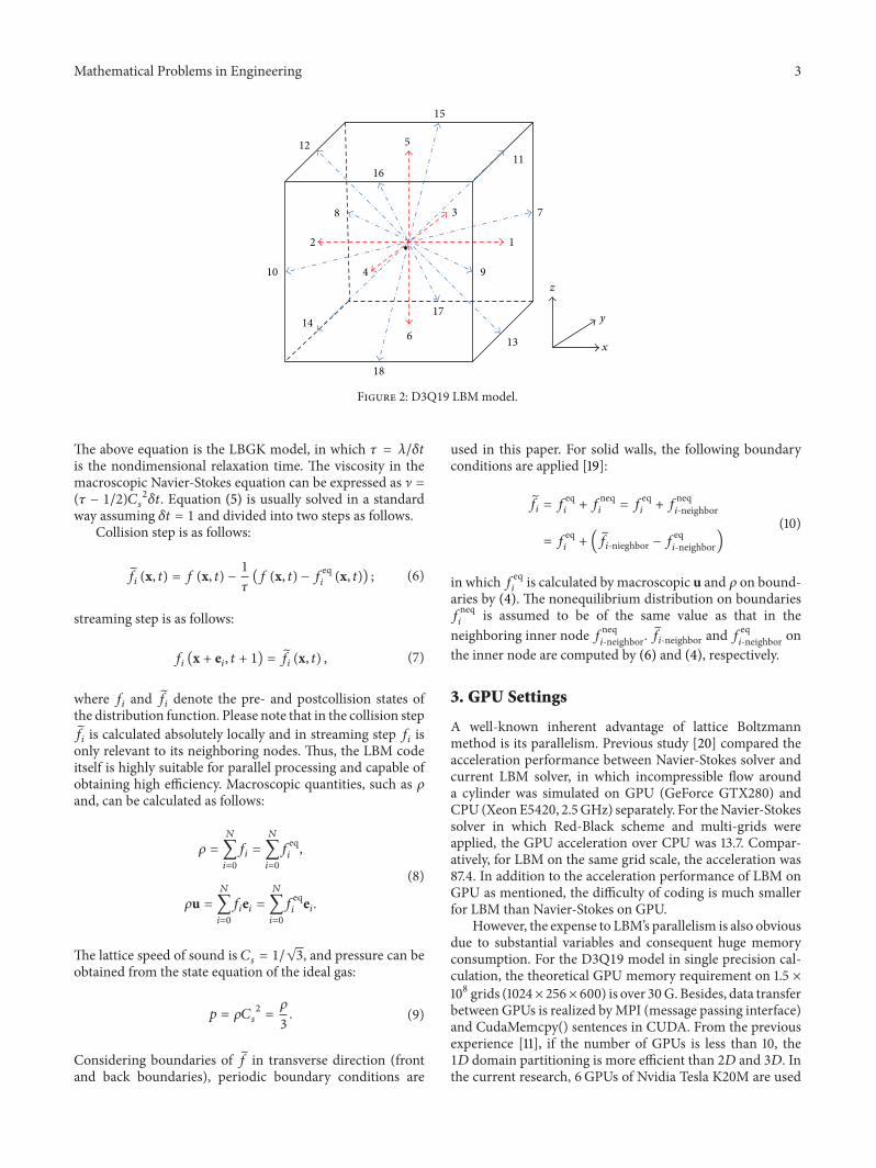
In the present paper D3Q19 scheme is used with par-ticle velocity as shown in Figure 2 119890
0(0 0 0) 119890
1(1 0 0)
1198902(minus1 0 0) 119890
3(0 1 0) 119890
4(0 minus1 0) 119890
5(0 0 1) 119890
6(0 0 minus1)
1198907(1 1 0) 119890
8(minus1 1 0) 119890
9(1 minus1 0) 119890
10(minus1 minus1 0) 119890
11(1 0 1)
11989012(minus1 0 1) 119890
13(1 0 minus1) 119890
14(minus1 0 minus1) 119890
15(0 1 1) 119890
16(0 minus1
1) 11989017(0 1 minus1) and 119890
18(0 minus1 minus1) Corresponding weighting
factors are 1206030= 13 120603
1sim 1206036= 118 and 120603
7sim 12060318= 136
If (3) is further discretized in both space 119909 and time 119905 thediscretized form can be written as
119891119894(x + e
119894120575119905 119905 + 120575119905) minus 119891
119894 (x 119905) = minus1
120591
(119891119894 (x 119905) minus 119891eq
119894(x 119905))
(5)
Mathematical Problems in Engineering 3
z
x
y
12
3
4
5
6
11
12
13
14
78
910
15
16
17
18
Figure 2 D3Q19 LBMmodel
The above equation is the LBGK model in which 120591 = 120582120575119905
is the nondimensional relaxation time The viscosity in themacroscopic Navier-Stokes equation can be expressed as ] =(120591 minus 12)119862
119904
2120575119905 Equation (5) is usually solved in a standard
way assuming 120575119905 = 1 and divided into two steps as followsCollision step is as follows
119891119894 (x 119905) = 119891 (x 119905) minus 1
120591
(119891 (x 119905) minus 119891eq119894(x 119905)) (6)
streaming step is as follows
119891119894(x + e
119894 119905 + 1) =
119891119894 (x 119905) (7)
where 119891119894and
119891119894denote the pre- and postcollision states of
the distribution function Please note that in the collision step119891119894is calculated absolutely locally and in streaming step 119891
119894is
only relevant to its neighboring nodes Thus the LBM codeitself is highly suitable for parallel processing and capable ofobtaining high efficiency Macroscopic quantities such as 120588and can be calculated as follows
120588 =
119873
sum
119894=0
119891119894=
119873
sum
119894=0
119891eq119894
120588u =119873
sum
119894=0
119891119894e119894=
119873
sum
119894=0
119891eq119894e119894
(8)
The lattice speed of sound is 119862119904= 1radic3 and pressure can be
obtained from the state equation of the ideal gas
119901 = 120588119862119904
2=
120588
3
(9)
Considering boundaries of 119891 in transverse direction (front
and back boundaries) periodic boundary conditions are
used in this paper For solid walls the following boundaryconditions are applied [19]
119891119894= 119891
eq119894+ 119891
neq119894
= 119891eq119894+ 119891
neq119894-neighbor
= 119891eq119894+ (
119891119894-nieghbor minus 119891
eq119894-neighbor)
(10)
in which 119891eq119894
is calculated by macroscopic u and 120588 on bound-aries by (4) The nonequilibrium distribution on boundaries119891neq119894
is assumed to be of the same value as that in theneighboring inner node 119891neq
119894-neighbor 119891119894-neighbor and 119891eq119894-neighbor on
the inner node are computed by (6) and (4) respectively
3 GPU Settings
A well-known inherent advantage of lattice Boltzmannmethod is its parallelism Previous study [20] compared theacceleration performance between Navier-Stokes solver andcurrent LBM solver in which incompressible flow arounda cylinder was simulated on GPU (GeForce GTX280) andCPU (XeonE5420 25GHz) separately For theNavier-Stokessolver in which Red-Black scheme and multi-grids wereapplied the GPU acceleration over CPU was 137 Compar-atively for LBM on the same grid scale the acceleration was874 In addition to the acceleration performance of LBM onGPU as mentioned the difficulty of coding is much smallerfor LBM than Navier-Stokes on GPU
However the expense to LBMrsquos parallelism is also obviousdue to substantial variables and consequent huge memoryconsumption For the D3Q19 model in single precision cal-culation the theoretical GPU memory requirement on 15 times108 grids (1024times 256times 600) is over 30G Besides data transferbetween GPUs is realized byMPI (message passing interface)and CudaMemcpy() sentences in CUDA From the previousexperience [11] if the number of GPUs is less than 10 the1119863 domain partitioning is more efficient than 2119863 and 3119863 Inthe current research 6GPUs of Nvidia Tesla K20M are used
4 Mathematical Problems in Engineering
Six processors
1024 times 256 times 100
1024 times 256 times 100
1024 times 256 times 100
Data communication MPI + CudaMemcpy
Figure 3 1D partitioning in 119911-direction
Lx
Lx1 Lx2
Ly
Lz
X
Y
Z
D
Figure 4 Physical model of jet in crossflow
20
15
10
5
10minus1
100
101
102
z+
U+
Sublayer
Turbulentcore
Figure 5 Streamwise velocity boundary layer profile
and the current 1119863 partitioning of the GPUs is illustrated inFigure 3
4 Physical and Numerical Models
The physical model of the jet in cross flow problem is shownin Figure 4 The computational domain is hexahedral inshape The mainstream flow is in 119909-direction while the jetis orthogonal to the mainstream in 119911-direction and ejectedfrom the bottom plane uniformly with diameter 119863 Originof the coordinates is located at the center of the roundjet exit The flow domain is zero-gradient in pressure and
no-slip boundary conditions are applied on the bottom planeexcluding the jet exit On transverse planes (with normalin 119910-direction) periodic boundary conditions are appliedThe inlet turbulent profile of velocity is given through acalculation procedure similar to the so-called ldquorescalingprocessrdquo as described in [21] The results presented in thispaper are based on flow parameters and boundary conditionslisted as follows
(i) Ejecting hole diameter (119863) = 75(ii) Domain length (119871119909119863 = (1198711199091+1198711199092)119863 = 5+7) = 12(iii) Domain span (119871119910119863) = 34
Mathematical Problems in Engineering 5
UUinfin
8
7
6
5
4
3
2
1
0minus04 0 04 08 12 16
LBM-DNSExperiment by Meyer et al
UUinfin
8
7
6
5
4
3
2
1
0minus04 0 04 08 12 16
WUinfin
0 08 16 24 32
8
7
6
5
4
3
2
1
0
WUinfin
0 08 16 24 32
8
7
6
5
4
3
2
1
0
LBM-DNSExperiment by Meyer et al
y = NY2
y = NY2
y = NY2
y = NY2
x = 05D
x = 3D
zD
x = 05D
x = 3D
zD
zD
zD
Figure 6 Streamwise and spanwise velocities profiles after the jet
(iv) Domain height (119871119911119863) = 64
(v) Free-stream turbulence intensity (TI) = 3
(vi) Boundary layer height (120575119863) = 02
(vii) Velocity ratio (VR = 119880119895119880infin) = 33
Reynolds number Re119895is defined based on jet velocity
119880119895and film hole diameter 119863 as Re
119895= 119880119895119863120592 The largest
Reynolds number Re119895reaches 3000 on grids (1024 times 256 times
600) and several calculations are performed with differentdimensions grids and jet locations trialed as shown inTable 1Thediscussion is based on the 1st case in the tableTheflow domain is kept in the ldquolow-speedrdquo range and velocitymagnitude is smaller than 03 times of the lattice sound speed
119862119904 Thus the LBGK model used in current study is suitable
[22]
5 Model Validation
Nondimensional time-averaged streamwise velocity 119880+
=
119880119906120591versus 119911+ = 119911119906
120591120592 is presented in Figure 5The location
is selected before the jet at 119909 = minus2119863 and 119910 = 1198731198842 toeliminate the influence from the jet A turbulent boundarylayer profile is obtained consisting of laminar sublayer andlog layer which is consistent with the Von Karman mixinglength theory
Further comparisons with experiments are made inregions where the mainstream is disturbed by the jet asshown in Figure 6 The experiments were done by Meyer
6 Mathematical Problems in Engineering
Table 1 Testing cases matrix
Jet diameter (119863) Domain (119871119909 times 119871119910 times 119871119911) Jet location (1198711199091) Mesh75 12D times 34D times 8D 26D 896 times 256 times 60075 136D times 34D times 8D 4D 1024 times 256 times 600100 10D times 5D times 8D 4D 1024 times 512 times 60075 85D times 34D times 64D 26D 640 times 256 times 48075 85D times 4D times 64D 26D 640 times 300 times 480
Etu
r10
0
10minus1
10minus2
10minus3
10minus4
10minus5
10minus6
10minus7
10minus8
100
101
102
Frequency (Hz)
minus53
x = 6D z = 4D y = NY2
Figure 7 Spectral power density of velocity fluctuations
et al [23 24] using stereoscopic PIV in a JICF problemTime-averaged streamwise and spanwise velocities (119880119880
infin
and119882119880infin) are presented in spanwise direction (with respect
to 119911119863) at locations of 119909 = 05119863 119910 = 1198731198842 and 119909 = 3119863 119910 =1198731198842 Results show good agreement with experimental dataIn current simulation a uniformly distributed velocity profileis set at the jet exit while in experiment the jet is suppliedthrough a tube and a turbulent profile has been developedinside itThus an overestimation of the jetrsquos momentum nearits boundary of the jet hole can be expected and seen inFigure 6
6 Results and Analysis
61 Energy Spectra Fast Fourier transformation (FFT) isperformed to a time series of turbulent energy 119864tur at thesample frequency of 2000 at 119909 = 6119863 119911 = 4119863 and 119910 =
1198731198842 The turbulent energy is defined as 119864tur = (12)(11990610158402+
V10158402 + 11990810158402) The corresponding turbulent power spectrum
is presented versus frequency as shown in Figure 7 Thecalculated turbulence decay rate is close to the theoreticalcanonical value of minus53 and no obvious spectrum buildupis observed which indicate the current mesh resolution isadequate
62 Velocity Field and Vorticity The 2119863 time-averagedvelocity (119880119882) and instantaneous velocity (119906 119908) fields in
the middle plane of 119910-direction (119910 = 1198731198842) are plottedin Figures 8(a) 8(b) and 8(c) respectively The correspond-ing vorticity distributions based on the time-averaged andinstantaneous velocities are also shown in the figure In Figure8(a) the vertical jet is bended toward exit by the mainstreamflow and phenomenon like flow passing a solid obstacle isobserved in the wake region As shown in the enlarging plotof flow field the approaching wall boundary layer meets withadverse pressure gradient before the jet and consequentlyseparates and forms the horseshoe vortex Considering thevorticity field negative and positive values are observed inleading edge and trailing edge along the jet trajectory andtrivial values exist in the wake region Instantaneous velocityand vorticity fields at time steps 80000 and 120000 areshown in Figures 8(b) and 8(c) respectively Generation andshedding of Kelvin-Helmholtz vortices are introduced by theshear layers between the mainstream and the jet on bothleading edge and trailing edge The shed vortices are mixingwith the mainstream and dissipated in the downstreamregion quickly In the wake region of the jet wake vortices areobserved through those nontrivial vorticity values howeverno vortex tube is directly observed in this cross section viewTo compare the time-averaged fields with their instantaneouscounterparts the Kelvin-Helmholtz vortices are not availableafter averaging which proves the shear-layer induced vorticesare inherently unsteady and periodic
Mathematical Problems in Engineering 7
Horseshoevortex
Vorticity_Y
004
003
002
0010
minus001
minus002
minus003
minus004
(a) Time-averaged
Shear-layervortices
Wakevortices
Ref vector
01
Vorticity_Y
004
003
002
0010
minus001
minus002
minus003
minus004
(b) Time step = 80000
Shear-layervortices
vorticesWake
Ref vector
01
Vorticity_Y
004
003
002
0010
minus001
minus002
minus003
minus004
(c) Time step = 120000
Figure 8 Time-averaged and instantaneous 2119863 velocity vector and vorticity at 119910 = 1198731198842 plane
The 2119863 instantaneous velocity (119906 V) and time-averagedvelocity (119880119881) fields are displayed at locations = 05119863 1119863and 2119863 respectively in Figure 9The corresponding vorticitydistributions are also displayed in the figure In Figure 9(a)the instantaneous velocity vectors and vorticity distributionsat time step 80000 are shown Separation of mainstreamoccurs near the mid-chord portion Further vortex sheddingand dissipation are observed in the downstream area Wakeregion is formed at the backside of the jet A characteristicflow pattern of the wake by the transverse jet is obtainedwhich is significantly different from that by a solid cylinder asdescribed in [1] In Figures 9(b) and 9(c) the time-averagedvelocity vectors and vorticity distributions are displayedSimilar to flow passing a solid cylinder along the stream-wise direction positive and negative values appear when
the mainstream starts to separate In downstream region thevorticity recovers to trivial values due to the dissipation ofthose periodically-shed vortices
The 2119863 time-averaged velocity (119881119882) fields are presentedin several streamwise planes at locations 119909 = 1119863 15119863and 3119863 in Figures 10(a) 10(b) and 10(c) respectively withvorticity distributions As shown in Figures 10(a) and 10(b)the CRVP system consists of two layers the upper one andthe lower one For a round hole as used in the current studythe rotating directions of the two pairs are the same Thisldquotwo-deckrdquo vortices structure is very similar to that observedin [2] by laser-induced fluorescence By comparing amongFigures 10(a) 10(b) and 10(c) it is found that when movingdownstream the vertical component (119882) of the 2119863 velocityreduces because of the jetrsquos bending At the same time
8 Mathematical Problems in Engineering
Wake vortices
Time step = 80000
Vorticity_Z
0008
0006
0004
0002
0010
minus0002
minus001
minus0004
minus0006
minus0008
(a) 119911 = 05119863
Time-averaged
Vorticity_Z
0008
0006
0004
0002
0010
minus0002
minus001
minus0004
minus0006
minus0008
(b) 119911 = 1119863
Ref vector
01
Time-averaged
Vorticity_Z
0008
0006
0004
0002
0010
minus0002
minus001
minus0004
minus0006
minus0008
(c) 119911 = 2119863
Figure 9 2119863 velocity vector and vorticity at planes of 119911 = 05119863 1119863 and 2119863
the lower layer vortices lift in vertical direction and weakenin strength Finally in far downstream region (119909 = 3119863) the119882-component is at the same level of 119881-component since thejet is almost fully bended and those two layers fully emergewith strength further weakened
63 Turbulent Statistics Reynolds stress distributions of11990610158401199081015840 11990610158401199061015840 and 119908
10158401199081015840 are plotted in the midplane of 119910-
direction (119910 = 1198731198842) in Figures 11(a) 11(b) and 11(c)respectively The shear stress component of the Reynoldsstress tensor is shown in Figure 11(a) Strong anisotropy of theflow field can be observed in the flow field Negative values of11990610158401199081015840 appear in the leading edge of the jet with positive values
in the trailing portion In the wake region both positiveand negative values exist with big nonuniformity In Figures11(b) and 11(c) the normal Reynolds stress is displayedFor both 119906
10158401199061015840 and 119908
10158401199081015840 the highest values appear in the
leading and trailing portions of the jet due to large velocitygradients Right behind the jet in the recirculation zoneboth components maintain some nontrivial values especially
11990810158401199081015840 indicating the wrapping motion around the jet by the
fluid flow
64 Coherent Structure The isosurfaces of second invariantof velocity gradient 119876 at time steps 80000 and 120000with domain height of 1198731198852 are plotted in Figure 12 Thedefinition of 119876 is given by (11) in tensor form
119876 =
1
2
(119882119894119895119882119894119895minus 119878119894119895119878119894119895) = minus
1
2
(
120597119906119895
120597119909119894
)(
120597119906119894
120597119909119895
)
119882119894119895=
120597119906119894
120597119909119895
minus
120597119906119895
120597119909119894
119878119894119895=
120597119906119894
120597119909119895
+
120597119906119895
120597119909119894
(11)
where119882119894119895and 119878119894119895denote the rate of rotation and rate of shear-
ing respectivelyThe hair-pin-shaped coherent structures areoriginated from the side and trailing edge of the ejectinghole and wrapping around the jet In the downstream regionthe hair-pin structure is weakened and dissipated into themainstream
Mathematical Problems in Engineering 9
CRVP
Vorticity_X
0008
0006
0004
00020
minus0002
minus0004
minus0006
minus0008
(a) 119909 = 1119863
CRVP
Vorticity_X
0008
0006
0004
00020
minus0002
minus0004
minus0006
minus0008
(b) 119909 = 15119863
CRVP
Ref vector
005
Vorticity_X
0008
0006
0004
00020
minus0002
minus0004
minus0006
minus0008
(c) 119909 = 3119863
Figure 10 Time-averaged 2119863 velocity vector and vorticity at planes of 119909 = 1119863 15119863 and 3119863
10 Mathematical Problems in Engineering
00015
00013
00011
00009
00007
00005
00003
00001
minus00001
minus00003
minus00005
u998400w998400
(a)
0004
00035
0003
00025
0002
00015
0001
00005
u998400u998400
(b)
00025
00023
00021
00019
00017
00015
00013
00011
00009
00007
00005
w998400w998400
(c)
Figure 11 Reynolds stress distribution at 119910 = 1198731198842 plane
(a) Time step = 80000 (b) Time step = 120000
Figure 12 Isosurfaces of second invariant of velocity gradient
7 Conclusion
A direct numerical simulation of jet in crossflow based onlattice Boltzmann method is performed on multi-GPUs Thecurrent simulation takes about 10 hours based on largest gridof 15 times 108 Several points can be summarized and concludedas follows
(1) A turbulent boundary layer is observed before the jet(119909 = minus2119863 119910 = 1198731198842) consisting of laminar sublayerand turbulent core After the jet at 119909 = 05119863 119910 =
1198731198842 and 119909 = 3119863 119910 = 1198731198842 time-averaged stream-wise and spanwise velocity components (119880119880
infinand
119882119880infin) are compared with experiments and good
agreement is obtained
Mathematical Problems in Engineering 11
(2) The turbulent energy spectrum is plotted versusfrequency at 119909 = 6119863 119911 = 4119863 and 119910 = 1198731198842 A decayrate close to the theoretical value of minus53 is observed
(3) 2119863 velocity vectors and vorticity fields are plotted in119910- 119911- and 119909-direction planes Unsteady shear-layervortices are formed and shed along the leading andtrailing side of the jet trajectory Horseshoe vortex isgenerated in the plate boundary layer before the jetTwo-deck structure of the CRVP is retained and thelower pair is observed to rise along the streamwisedirection
(4) The normal components (11990610158401199061015840 and 11990810158401199081015840) and shearcomponent (11990610158401199081015840) of the Reynolds stress are revealedin the 119910 = 1198731198842 plane Strong anisotropy is observedfor the flow field due to the shear layer and wake
(5) Coherent structure represented by the second invari-ant of velocity gradient (119876) is plotted at differenttime steps The characteristic hair-pin vortices areobserved
Conflict of Interests
The authors declare that there is no any conflict of interestsregarding the publication of this paper
Acknowledgments
The work is supported by 973 Project of China(2013CB035702) the National Natural Science Foundationof China (11302165 and 11402191) and Postdoctoral ScienceFoundation of China (2013M540741)
References
[1] T F Fric and A Roshko ldquoVortical structure in the wake of atransverse jetrdquo Journal of Fluid Mechanics vol 279 pp 1ndash471994
[2] B A Haven andMKurosaka ldquoKidney and anti-kidney vorticesin crossflow jetsrdquo Journal of FluidMechanics vol 352 pp 27ndash641997
[3] S Y Chen and G D Doolen ldquoLattice Boltzmann method forfluid flowsrdquoAnnual Review of Fluid Mechanics vol 30 pp 329ndash364 1998
[4] Y L He Y Wang and Q Li Lattice Boltzmann Method Theoryand Applications Science Press Beijing China 2009
[5] L Chen Q Kang Y Mu Y-L He and W-Q Tao ldquoA criticalreview of the pseudopotential multiphase lattice Boltzmannmodel methods and applicationsrdquo International Journal of Heatand Mass Transfer vol 76 pp 210ndash236 2014
[6] C K Aidun and J R Clausen ldquoLattice-Boltzmann method forcomplex flowsrdquo Annual Review of Fluid Mechanics vol 42 pp439ndash472 2010
[7] nVIDIA ldquoNVIDIA CUDA Compute Unified Device Architec-ture Programming Guide Version 20rdquo nVIDIA 2008
[8] I Buck T Foley and D Horn ldquoBrook for GPUs stream com-puting on graphics hardwarerdquo ACM Transactions on Graphicsvol 23 pp 777ndash786 2004
[9] J Kruger and R Westermann ldquoLinear algebra operators forGPU implementation of numerical algorithmsrdquo ACM Transac-tions on Graphics vol 22 no 3 pp 908ndash916 2003
[10] S Ogawa and T Aoki ldquoGPU Computing for 2-dimensionalincompressible-flow simulation based on multi-grid methodrdquoTransactions of JSCES Article ID 20090021 2009
[11] W Xian and A Takayuki ldquoMulti-GPU performance of incom-pressible flow computation by lattice Boltzmann method onGPUclusterrdquoParallel Computing vol 37 no 9 pp 521ndash535 2011
[12] D Rossinelli M Bergdorf G-H Cottet and P KoumoutsakosldquoGPU accelerated simulations of bluff body flows using vortexparticle methodsrdquo Journal of Computational Physics vol 229no 9 pp 3316ndash3333 2010
[13] T Shimokawabe T Aoki J Ishida K Kawano and C Muroildquo145 TFlops performance on 3990 GPUs of TSUBAME 20supercomputer for an operational weather predictionrdquo in Pro-ceedings of the 11th International Conference on ComputationalScience (ICCS rsquo11) vol 4 pp 1535ndash1544 June 2011
[14] X Wang and T Aoki ldquoHigh performance computation bymulti-node GPU cluster-TSUBAME 20 on the air flow inan urban city using lattice Boltzmann methodrdquo InternationalJournal of Aerospace and Lightweight Structures vol 2 no 1 pp77ndash86 2012
[15] T Miki X Wang T Aoki et al ldquoPatient-specific modellingof pulmonary airflow using GPU cluster for the applicationin medical practicerdquo Computer Methods in Biomechanics andBiomedical Engineering vol 15 no 7 pp 771ndash778 2012
[16] XWang Y ShangguanNOnoderaH Kobayashi andT AokildquoDirect numerical simulation and large eddy simulation on aturbulent wall-bounded flow using lattice boltzmann methodandmultiple GPUsrdquoMathematical Problems in Engineering vol2014 Article ID 742432 10 pages 2014
[17] P L Bhatnagar E P Gross andMKrook ldquoAmodel for collisionprocesses in gasesrdquo Physical Review vol 94 no 3 pp 511ndash5251954
[18] Y H Qian D DrsquoHumieres and P Lallemand ldquoLattice BGKmodels for navier-stokes equationrdquo EuroPhysics Letters vol 17no 6 pp 479ndash484 1992
[19] Z-L Guo C-G Zheng and B-C Shi ldquoNon-equilibriumextrapolation method for velocity and pressure boundary con-ditions in the lattice boltzmann methodrdquo Chinese Physics vol11 no 4 pp 366ndash374 2002
[20] D Xu G Chen X Wang and Y Li ldquoDirect numericalsimulation of the wall-bounded turbulent flow by Lattice Boltz-mannmethod based onmulti-GPUsrdquoAppliedMathematics andMechanics vol 34 no 9 pp 1ndash9 2013
[21] F Muldoon and S Acharya ldquoDirect numerical simulation ofpulsed jets-in-crossflowrdquoComputers amp Fluids vol 39 no 10 pp1745ndash1773 2010
[22] Z L Guo and C G Zheng Theory and Applications of LatticeBoltzmann Method Science Press Beijing China 2010
[23] K E Meyer O Ozcan P S Larsen and C H WestergaardldquoSteroscopic PIV measurements in a jet in crossflowrdquo in Pro-ceedings of the 2nd International Symposium on Turbulence andShear Flow Phenomena Stockholm Sweden June 2001
[24] K E Meyer O Ozcan P S Larsen and C H WestergaardldquoFlow mapping of a jet in crossflow with stereoscopic PIVrdquoJournal of Visualization vol 5 no 3 pp 225ndash231 2002
Submit your manuscripts athttpwwwhindawicom
Hindawi Publishing Corporationhttpwwwhindawicom Volume 2014
MathematicsJournal of
Hindawi Publishing Corporationhttpwwwhindawicom Volume 2014
Mathematical Problems in Engineering
Hindawi Publishing Corporationhttpwwwhindawicom
Differential EquationsInternational Journal of
Volume 2014
Applied MathematicsJournal of
Hindawi Publishing Corporationhttpwwwhindawicom Volume 2014
Probability and StatisticsHindawi Publishing Corporationhttpwwwhindawicom Volume 2014
Journal of
Hindawi Publishing Corporationhttpwwwhindawicom Volume 2014
Mathematical PhysicsAdvances in
Complex AnalysisJournal of
Hindawi Publishing Corporationhttpwwwhindawicom Volume 2014
OptimizationJournal of
Hindawi Publishing Corporationhttpwwwhindawicom Volume 2014
CombinatoricsHindawi Publishing Corporationhttpwwwhindawicom Volume 2014
International Journal of
Hindawi Publishing Corporationhttpwwwhindawicom Volume 2014
Operations ResearchAdvances in
Journal of
Hindawi Publishing Corporationhttpwwwhindawicom Volume 2014
Function Spaces
Abstract and Applied AnalysisHindawi Publishing Corporationhttpwwwhindawicom Volume 2014
International Journal of Mathematics and Mathematical Sciences
Hindawi Publishing Corporationhttpwwwhindawicom Volume 2014
The Scientific World JournalHindawi Publishing Corporation httpwwwhindawicom Volume 2014
Hindawi Publishing Corporationhttpwwwhindawicom Volume 2014
Algebra
Discrete Dynamics in Nature and Society
Hindawi Publishing Corporationhttpwwwhindawicom Volume 2014
Hindawi Publishing Corporationhttpwwwhindawicom Volume 2014
Decision SciencesAdvances in
Discrete MathematicsJournal of
Hindawi Publishing Corporationhttpwwwhindawicom
Volume 2014 Hindawi Publishing Corporationhttpwwwhindawicom Volume 2014
Stochastic AnalysisInternational Journal of

2 Mathematical Problems in Engineering
Counter-rotating vortex pair
Wake vorticesHorseshoe vortices
Jet shear-layervortices
Wall
Crossflow
Figure 1 Four vortical structures associated with the JICF as in [1]
the parallel processing with low efficiency Thus a highlyparallel scheme is extremely helpful to those large-scalesimulations of turbulent flow field
Lattice Boltzmannmethod (LBM) has been regarded as apromising candidate for years due to its major merits of fullyparallel algorithm Unlike conventional numerical schemesbased on assumption and discretizations of macroscopiccontinuum the LBM adopts microscopic models [3] Otheradvantages of LBM include (1) easy treatment of boundaryconditions and (2) easy programming As a result the LBMhas its wide application in scientific and engineering researchsuch as Biofluid and porous medium [4ndash6] However toresolve the turbulent flow LBM-based DNS and LES requirea very high grid resolution and thus huge computationresource is needed
Graphic Processing Unit (GPU) brings excellent hard-ware conditions for these simulations With the develop-ment of computing platforms for example CUDA [7] andOpenCL the use of GPU to accelerate nongraphic computa-tions has drawn much more attention [8 9] Due to its highperformance of floating-point arithmetic operation togetherwith wide memory bandwidth and good programmabilitygeneral-purpose GPU (GPGPU) has its huge advantage overCPU in turbulent flow simulation [10ndash12] and thus hasbeen applied in fields like weather prediction crystal growthprocess and air flow in the city [13ndash15]
The feasibility for LBM-based DNS has some preliminaryvalidation for turbulent flows between parallel plates [16]further verification for JICF is still empty In this paper thelattice Boltzmann based DNS on JICF model is performedusing D3Q19model in multi-GPUs With further validationof this code this paper aims to resolve the JICF flow fieldincluding the time-averaged and instantaneous velocitiesvorticities and turbulent quantities of Reynolds stress Thecharacteristic coherent hairpin structures are also revealedand discussed
2 Lattice Boltzmann Equations
Lattice Boltzmann equation is the special form of theBoltzmann-BGK equation [17] in which discretizationapplies to velocity time and space The Boltzmann equation
for the discrete velocity distribution on a discrete lattice is asfollows
120597119891119894
120597119905
+ e119894sdot nabla119891119894= Ω119894 (1)
where119891119894is the particle velocity distribution function and e
119894is
the particle velocity in the 119894th direction Here the scheme ofLBM is described as D119898Q119899 [18] ldquoD119898rdquomeans ldquo119898 dimensionrdquoand ldquoQ119899rdquo stands for ldquo119899 lattice speedsrdquo For two-dimensionalproblems D2Q9 model is most commonly used and means2119863 and 9 speeds For three-dimensional problems severalcubic models are used such as D3Q13 D3Q15 D3Q19 andD3Q27 (119899 = 13 15 19 or 27) Ω
119894is the collision operator
With Boltzmann-BGK approximation
Ω119894= minus
1
120591
(119891119894minus 119891
eq119894) (2)
Combine (1) and (2) then it changes to
120597119891119894
120597119905
+ e119894sdot nabla119891119894= minus
1
120591
(119891119894minus 119891
eq119894) (3)
where119891eq119894
is the local equilibrium and 120591 is the relaxation timeThe equilibriumdistribution formhas to be correctly adoptedto restore the Navier-Stokes equations For 3119863 models withthe 13- 15- 19- and 27-speed lattice an appropriate distribu-tion function is written as
119891eq119894= 120588120603119894[1 + 3e
119894sdot u + 9
2
(e119894sdot u)2 minus 3
2
u sdot u] (4)
In the present paper D3Q19 scheme is used with par-ticle velocity as shown in Figure 2 119890
0(0 0 0) 119890
1(1 0 0)
1198902(minus1 0 0) 119890
3(0 1 0) 119890
4(0 minus1 0) 119890
5(0 0 1) 119890
6(0 0 minus1)
1198907(1 1 0) 119890
8(minus1 1 0) 119890
9(1 minus1 0) 119890
10(minus1 minus1 0) 119890
11(1 0 1)
11989012(minus1 0 1) 119890
13(1 0 minus1) 119890
14(minus1 0 minus1) 119890
15(0 1 1) 119890
16(0 minus1
1) 11989017(0 1 minus1) and 119890
18(0 minus1 minus1) Corresponding weighting
factors are 1206030= 13 120603
1sim 1206036= 118 and 120603
7sim 12060318= 136
If (3) is further discretized in both space 119909 and time 119905 thediscretized form can be written as
119891119894(x + e
119894120575119905 119905 + 120575119905) minus 119891
119894 (x 119905) = minus1
120591
(119891119894 (x 119905) minus 119891eq
119894(x 119905))
(5)
Mathematical Problems in Engineering 3
z
x
y
12
3
4
5
6
11
12
13
14
78
910
15
16
17
18
Figure 2 D3Q19 LBMmodel
The above equation is the LBGK model in which 120591 = 120582120575119905
is the nondimensional relaxation time The viscosity in themacroscopic Navier-Stokes equation can be expressed as ] =(120591 minus 12)119862
119904
2120575119905 Equation (5) is usually solved in a standard
way assuming 120575119905 = 1 and divided into two steps as followsCollision step is as follows
119891119894 (x 119905) = 119891 (x 119905) minus 1
120591
(119891 (x 119905) minus 119891eq119894(x 119905)) (6)
streaming step is as follows
119891119894(x + e
119894 119905 + 1) =
119891119894 (x 119905) (7)
where 119891119894and
119891119894denote the pre- and postcollision states of
the distribution function Please note that in the collision step119891119894is calculated absolutely locally and in streaming step 119891
119894is
only relevant to its neighboring nodes Thus the LBM codeitself is highly suitable for parallel processing and capable ofobtaining high efficiency Macroscopic quantities such as 120588and can be calculated as follows
120588 =
119873
sum
119894=0
119891119894=
119873
sum
119894=0
119891eq119894
120588u =119873
sum
119894=0
119891119894e119894=
119873
sum
119894=0
119891eq119894e119894
(8)
The lattice speed of sound is 119862119904= 1radic3 and pressure can be
obtained from the state equation of the ideal gas
119901 = 120588119862119904
2=
120588
3
(9)
Considering boundaries of 119891 in transverse direction (front
and back boundaries) periodic boundary conditions are
used in this paper For solid walls the following boundaryconditions are applied [19]
119891119894= 119891
eq119894+ 119891
neq119894
= 119891eq119894+ 119891
neq119894-neighbor
= 119891eq119894+ (
119891119894-nieghbor minus 119891
eq119894-neighbor)
(10)
in which 119891eq119894
is calculated by macroscopic u and 120588 on bound-aries by (4) The nonequilibrium distribution on boundaries119891neq119894
is assumed to be of the same value as that in theneighboring inner node 119891neq
119894-neighbor 119891119894-neighbor and 119891eq119894-neighbor on
the inner node are computed by (6) and (4) respectively
3 GPU Settings
A well-known inherent advantage of lattice Boltzmannmethod is its parallelism Previous study [20] compared theacceleration performance between Navier-Stokes solver andcurrent LBM solver in which incompressible flow arounda cylinder was simulated on GPU (GeForce GTX280) andCPU (XeonE5420 25GHz) separately For theNavier-Stokessolver in which Red-Black scheme and multi-grids wereapplied the GPU acceleration over CPU was 137 Compar-atively for LBM on the same grid scale the acceleration was874 In addition to the acceleration performance of LBM onGPU as mentioned the difficulty of coding is much smallerfor LBM than Navier-Stokes on GPU
However the expense to LBMrsquos parallelism is also obviousdue to substantial variables and consequent huge memoryconsumption For the D3Q19 model in single precision cal-culation the theoretical GPU memory requirement on 15 times108 grids (1024times 256times 600) is over 30G Besides data transferbetween GPUs is realized byMPI (message passing interface)and CudaMemcpy() sentences in CUDA From the previousexperience [11] if the number of GPUs is less than 10 the1119863 domain partitioning is more efficient than 2119863 and 3119863 Inthe current research 6GPUs of Nvidia Tesla K20M are used
4 Mathematical Problems in Engineering
Six processors
1024 times 256 times 100
1024 times 256 times 100
1024 times 256 times 100
Data communication MPI + CudaMemcpy
Figure 3 1D partitioning in 119911-direction
Lx
Lx1 Lx2
Ly
Lz
X
Y
Z
D
Figure 4 Physical model of jet in crossflow
20
15
10
5
10minus1
100
101
102
z+
U+
Sublayer
Turbulentcore
Figure 5 Streamwise velocity boundary layer profile
and the current 1119863 partitioning of the GPUs is illustrated inFigure 3
4 Physical and Numerical Models
The physical model of the jet in cross flow problem is shownin Figure 4 The computational domain is hexahedral inshape The mainstream flow is in 119909-direction while the jetis orthogonal to the mainstream in 119911-direction and ejectedfrom the bottom plane uniformly with diameter 119863 Originof the coordinates is located at the center of the roundjet exit The flow domain is zero-gradient in pressure and
no-slip boundary conditions are applied on the bottom planeexcluding the jet exit On transverse planes (with normalin 119910-direction) periodic boundary conditions are appliedThe inlet turbulent profile of velocity is given through acalculation procedure similar to the so-called ldquorescalingprocessrdquo as described in [21] The results presented in thispaper are based on flow parameters and boundary conditionslisted as follows
(i) Ejecting hole diameter (119863) = 75(ii) Domain length (119871119909119863 = (1198711199091+1198711199092)119863 = 5+7) = 12(iii) Domain span (119871119910119863) = 34
Mathematical Problems in Engineering 5
UUinfin
8
7
6
5
4
3
2
1
0minus04 0 04 08 12 16
LBM-DNSExperiment by Meyer et al
UUinfin
8
7
6
5
4
3
2
1
0minus04 0 04 08 12 16
WUinfin
0 08 16 24 32
8
7
6
5
4
3
2
1
0
WUinfin
0 08 16 24 32
8
7
6
5
4
3
2
1
0
LBM-DNSExperiment by Meyer et al
y = NY2
y = NY2
y = NY2
y = NY2
x = 05D
x = 3D
zD
x = 05D
x = 3D
zD
zD
zD
Figure 6 Streamwise and spanwise velocities profiles after the jet
(iv) Domain height (119871119911119863) = 64
(v) Free-stream turbulence intensity (TI) = 3
(vi) Boundary layer height (120575119863) = 02
(vii) Velocity ratio (VR = 119880119895119880infin) = 33
Reynolds number Re119895is defined based on jet velocity
119880119895and film hole diameter 119863 as Re
119895= 119880119895119863120592 The largest
Reynolds number Re119895reaches 3000 on grids (1024 times 256 times
600) and several calculations are performed with differentdimensions grids and jet locations trialed as shown inTable 1Thediscussion is based on the 1st case in the tableTheflow domain is kept in the ldquolow-speedrdquo range and velocitymagnitude is smaller than 03 times of the lattice sound speed
119862119904 Thus the LBGK model used in current study is suitable
[22]
5 Model Validation
Nondimensional time-averaged streamwise velocity 119880+
=
119880119906120591versus 119911+ = 119911119906
120591120592 is presented in Figure 5The location
is selected before the jet at 119909 = minus2119863 and 119910 = 1198731198842 toeliminate the influence from the jet A turbulent boundarylayer profile is obtained consisting of laminar sublayer andlog layer which is consistent with the Von Karman mixinglength theory
Further comparisons with experiments are made inregions where the mainstream is disturbed by the jet asshown in Figure 6 The experiments were done by Meyer
6 Mathematical Problems in Engineering
Table 1 Testing cases matrix
Jet diameter (119863) Domain (119871119909 times 119871119910 times 119871119911) Jet location (1198711199091) Mesh75 12D times 34D times 8D 26D 896 times 256 times 60075 136D times 34D times 8D 4D 1024 times 256 times 600100 10D times 5D times 8D 4D 1024 times 512 times 60075 85D times 34D times 64D 26D 640 times 256 times 48075 85D times 4D times 64D 26D 640 times 300 times 480
Etu
r10
0
10minus1
10minus2
10minus3
10minus4
10minus5
10minus6
10minus7
10minus8
100
101
102
Frequency (Hz)
minus53
x = 6D z = 4D y = NY2
Figure 7 Spectral power density of velocity fluctuations
et al [23 24] using stereoscopic PIV in a JICF problemTime-averaged streamwise and spanwise velocities (119880119880
infin
and119882119880infin) are presented in spanwise direction (with respect
to 119911119863) at locations of 119909 = 05119863 119910 = 1198731198842 and 119909 = 3119863 119910 =1198731198842 Results show good agreement with experimental dataIn current simulation a uniformly distributed velocity profileis set at the jet exit while in experiment the jet is suppliedthrough a tube and a turbulent profile has been developedinside itThus an overestimation of the jetrsquos momentum nearits boundary of the jet hole can be expected and seen inFigure 6
6 Results and Analysis
61 Energy Spectra Fast Fourier transformation (FFT) isperformed to a time series of turbulent energy 119864tur at thesample frequency of 2000 at 119909 = 6119863 119911 = 4119863 and 119910 =
1198731198842 The turbulent energy is defined as 119864tur = (12)(11990610158402+
V10158402 + 11990810158402) The corresponding turbulent power spectrum
is presented versus frequency as shown in Figure 7 Thecalculated turbulence decay rate is close to the theoreticalcanonical value of minus53 and no obvious spectrum buildupis observed which indicate the current mesh resolution isadequate
62 Velocity Field and Vorticity The 2119863 time-averagedvelocity (119880119882) and instantaneous velocity (119906 119908) fields in
the middle plane of 119910-direction (119910 = 1198731198842) are plottedin Figures 8(a) 8(b) and 8(c) respectively The correspond-ing vorticity distributions based on the time-averaged andinstantaneous velocities are also shown in the figure In Figure8(a) the vertical jet is bended toward exit by the mainstreamflow and phenomenon like flow passing a solid obstacle isobserved in the wake region As shown in the enlarging plotof flow field the approaching wall boundary layer meets withadverse pressure gradient before the jet and consequentlyseparates and forms the horseshoe vortex Considering thevorticity field negative and positive values are observed inleading edge and trailing edge along the jet trajectory andtrivial values exist in the wake region Instantaneous velocityand vorticity fields at time steps 80000 and 120000 areshown in Figures 8(b) and 8(c) respectively Generation andshedding of Kelvin-Helmholtz vortices are introduced by theshear layers between the mainstream and the jet on bothleading edge and trailing edge The shed vortices are mixingwith the mainstream and dissipated in the downstreamregion quickly In the wake region of the jet wake vortices areobserved through those nontrivial vorticity values howeverno vortex tube is directly observed in this cross section viewTo compare the time-averaged fields with their instantaneouscounterparts the Kelvin-Helmholtz vortices are not availableafter averaging which proves the shear-layer induced vorticesare inherently unsteady and periodic
Mathematical Problems in Engineering 7
Horseshoevortex
Vorticity_Y
004
003
002
0010
minus001
minus002
minus003
minus004
(a) Time-averaged
Shear-layervortices
Wakevortices
Ref vector
01
Vorticity_Y
004
003
002
0010
minus001
minus002
minus003
minus004
(b) Time step = 80000
Shear-layervortices
vorticesWake
Ref vector
01
Vorticity_Y
004
003
002
0010
minus001
minus002
minus003
minus004
(c) Time step = 120000
Figure 8 Time-averaged and instantaneous 2119863 velocity vector and vorticity at 119910 = 1198731198842 plane
The 2119863 instantaneous velocity (119906 V) and time-averagedvelocity (119880119881) fields are displayed at locations = 05119863 1119863and 2119863 respectively in Figure 9The corresponding vorticitydistributions are also displayed in the figure In Figure 9(a)the instantaneous velocity vectors and vorticity distributionsat time step 80000 are shown Separation of mainstreamoccurs near the mid-chord portion Further vortex sheddingand dissipation are observed in the downstream area Wakeregion is formed at the backside of the jet A characteristicflow pattern of the wake by the transverse jet is obtainedwhich is significantly different from that by a solid cylinder asdescribed in [1] In Figures 9(b) and 9(c) the time-averagedvelocity vectors and vorticity distributions are displayedSimilar to flow passing a solid cylinder along the stream-wise direction positive and negative values appear when
the mainstream starts to separate In downstream region thevorticity recovers to trivial values due to the dissipation ofthose periodically-shed vortices
The 2119863 time-averaged velocity (119881119882) fields are presentedin several streamwise planes at locations 119909 = 1119863 15119863and 3119863 in Figures 10(a) 10(b) and 10(c) respectively withvorticity distributions As shown in Figures 10(a) and 10(b)the CRVP system consists of two layers the upper one andthe lower one For a round hole as used in the current studythe rotating directions of the two pairs are the same Thisldquotwo-deckrdquo vortices structure is very similar to that observedin [2] by laser-induced fluorescence By comparing amongFigures 10(a) 10(b) and 10(c) it is found that when movingdownstream the vertical component (119882) of the 2119863 velocityreduces because of the jetrsquos bending At the same time
8 Mathematical Problems in Engineering
Wake vortices
Time step = 80000
Vorticity_Z
0008
0006
0004
0002
0010
minus0002
minus001
minus0004
minus0006
minus0008
(a) 119911 = 05119863
Time-averaged
Vorticity_Z
0008
0006
0004
0002
0010
minus0002
minus001
minus0004
minus0006
minus0008
(b) 119911 = 1119863
Ref vector
01
Time-averaged
Vorticity_Z
0008
0006
0004
0002
0010
minus0002
minus001
minus0004
minus0006
minus0008
(c) 119911 = 2119863
Figure 9 2119863 velocity vector and vorticity at planes of 119911 = 05119863 1119863 and 2119863
the lower layer vortices lift in vertical direction and weakenin strength Finally in far downstream region (119909 = 3119863) the119882-component is at the same level of 119881-component since thejet is almost fully bended and those two layers fully emergewith strength further weakened
63 Turbulent Statistics Reynolds stress distributions of11990610158401199081015840 11990610158401199061015840 and 119908
10158401199081015840 are plotted in the midplane of 119910-
direction (119910 = 1198731198842) in Figures 11(a) 11(b) and 11(c)respectively The shear stress component of the Reynoldsstress tensor is shown in Figure 11(a) Strong anisotropy of theflow field can be observed in the flow field Negative values of11990610158401199081015840 appear in the leading edge of the jet with positive values
in the trailing portion In the wake region both positiveand negative values exist with big nonuniformity In Figures11(b) and 11(c) the normal Reynolds stress is displayedFor both 119906
10158401199061015840 and 119908
10158401199081015840 the highest values appear in the
leading and trailing portions of the jet due to large velocitygradients Right behind the jet in the recirculation zoneboth components maintain some nontrivial values especially
11990810158401199081015840 indicating the wrapping motion around the jet by the
fluid flow
64 Coherent Structure The isosurfaces of second invariantof velocity gradient 119876 at time steps 80000 and 120000with domain height of 1198731198852 are plotted in Figure 12 Thedefinition of 119876 is given by (11) in tensor form
119876 =
1
2
(119882119894119895119882119894119895minus 119878119894119895119878119894119895) = minus
1
2
(
120597119906119895
120597119909119894
)(
120597119906119894
120597119909119895
)
119882119894119895=
120597119906119894
120597119909119895
minus
120597119906119895
120597119909119894
119878119894119895=
120597119906119894
120597119909119895
+
120597119906119895
120597119909119894
(11)
where119882119894119895and 119878119894119895denote the rate of rotation and rate of shear-
ing respectivelyThe hair-pin-shaped coherent structures areoriginated from the side and trailing edge of the ejectinghole and wrapping around the jet In the downstream regionthe hair-pin structure is weakened and dissipated into themainstream
Mathematical Problems in Engineering 9
CRVP
Vorticity_X
0008
0006
0004
00020
minus0002
minus0004
minus0006
minus0008
(a) 119909 = 1119863
CRVP
Vorticity_X
0008
0006
0004
00020
minus0002
minus0004
minus0006
minus0008
(b) 119909 = 15119863
CRVP
Ref vector
005
Vorticity_X
0008
0006
0004
00020
minus0002
minus0004
minus0006
minus0008
(c) 119909 = 3119863
Figure 10 Time-averaged 2119863 velocity vector and vorticity at planes of 119909 = 1119863 15119863 and 3119863
10 Mathematical Problems in Engineering
00015
00013
00011
00009
00007
00005
00003
00001
minus00001
minus00003
minus00005
u998400w998400
(a)
0004
00035
0003
00025
0002
00015
0001
00005
u998400u998400
(b)
00025
00023
00021
00019
00017
00015
00013
00011
00009
00007
00005
w998400w998400
(c)
Figure 11 Reynolds stress distribution at 119910 = 1198731198842 plane
(a) Time step = 80000 (b) Time step = 120000
Figure 12 Isosurfaces of second invariant of velocity gradient
7 Conclusion
A direct numerical simulation of jet in crossflow based onlattice Boltzmann method is performed on multi-GPUs Thecurrent simulation takes about 10 hours based on largest gridof 15 times 108 Several points can be summarized and concludedas follows
(1) A turbulent boundary layer is observed before the jet(119909 = minus2119863 119910 = 1198731198842) consisting of laminar sublayerand turbulent core After the jet at 119909 = 05119863 119910 =
1198731198842 and 119909 = 3119863 119910 = 1198731198842 time-averaged stream-wise and spanwise velocity components (119880119880
infinand
119882119880infin) are compared with experiments and good
agreement is obtained
Mathematical Problems in Engineering 11
(2) The turbulent energy spectrum is plotted versusfrequency at 119909 = 6119863 119911 = 4119863 and 119910 = 1198731198842 A decayrate close to the theoretical value of minus53 is observed
(3) 2119863 velocity vectors and vorticity fields are plotted in119910- 119911- and 119909-direction planes Unsteady shear-layervortices are formed and shed along the leading andtrailing side of the jet trajectory Horseshoe vortex isgenerated in the plate boundary layer before the jetTwo-deck structure of the CRVP is retained and thelower pair is observed to rise along the streamwisedirection
(4) The normal components (11990610158401199061015840 and 11990810158401199081015840) and shearcomponent (11990610158401199081015840) of the Reynolds stress are revealedin the 119910 = 1198731198842 plane Strong anisotropy is observedfor the flow field due to the shear layer and wake
(5) Coherent structure represented by the second invari-ant of velocity gradient (119876) is plotted at differenttime steps The characteristic hair-pin vortices areobserved
Conflict of Interests
The authors declare that there is no any conflict of interestsregarding the publication of this paper
Acknowledgments
The work is supported by 973 Project of China(2013CB035702) the National Natural Science Foundationof China (11302165 and 11402191) and Postdoctoral ScienceFoundation of China (2013M540741)
References
[1] T F Fric and A Roshko ldquoVortical structure in the wake of atransverse jetrdquo Journal of Fluid Mechanics vol 279 pp 1ndash471994
[2] B A Haven andMKurosaka ldquoKidney and anti-kidney vorticesin crossflow jetsrdquo Journal of FluidMechanics vol 352 pp 27ndash641997
[3] S Y Chen and G D Doolen ldquoLattice Boltzmann method forfluid flowsrdquoAnnual Review of Fluid Mechanics vol 30 pp 329ndash364 1998
[4] Y L He Y Wang and Q Li Lattice Boltzmann Method Theoryand Applications Science Press Beijing China 2009
[5] L Chen Q Kang Y Mu Y-L He and W-Q Tao ldquoA criticalreview of the pseudopotential multiphase lattice Boltzmannmodel methods and applicationsrdquo International Journal of Heatand Mass Transfer vol 76 pp 210ndash236 2014
[6] C K Aidun and J R Clausen ldquoLattice-Boltzmann method forcomplex flowsrdquo Annual Review of Fluid Mechanics vol 42 pp439ndash472 2010
[7] nVIDIA ldquoNVIDIA CUDA Compute Unified Device Architec-ture Programming Guide Version 20rdquo nVIDIA 2008
[8] I Buck T Foley and D Horn ldquoBrook for GPUs stream com-puting on graphics hardwarerdquo ACM Transactions on Graphicsvol 23 pp 777ndash786 2004
[9] J Kruger and R Westermann ldquoLinear algebra operators forGPU implementation of numerical algorithmsrdquo ACM Transac-tions on Graphics vol 22 no 3 pp 908ndash916 2003
[10] S Ogawa and T Aoki ldquoGPU Computing for 2-dimensionalincompressible-flow simulation based on multi-grid methodrdquoTransactions of JSCES Article ID 20090021 2009
[11] W Xian and A Takayuki ldquoMulti-GPU performance of incom-pressible flow computation by lattice Boltzmann method onGPUclusterrdquoParallel Computing vol 37 no 9 pp 521ndash535 2011
[12] D Rossinelli M Bergdorf G-H Cottet and P KoumoutsakosldquoGPU accelerated simulations of bluff body flows using vortexparticle methodsrdquo Journal of Computational Physics vol 229no 9 pp 3316ndash3333 2010
[13] T Shimokawabe T Aoki J Ishida K Kawano and C Muroildquo145 TFlops performance on 3990 GPUs of TSUBAME 20supercomputer for an operational weather predictionrdquo in Pro-ceedings of the 11th International Conference on ComputationalScience (ICCS rsquo11) vol 4 pp 1535ndash1544 June 2011
[14] X Wang and T Aoki ldquoHigh performance computation bymulti-node GPU cluster-TSUBAME 20 on the air flow inan urban city using lattice Boltzmann methodrdquo InternationalJournal of Aerospace and Lightweight Structures vol 2 no 1 pp77ndash86 2012
[15] T Miki X Wang T Aoki et al ldquoPatient-specific modellingof pulmonary airflow using GPU cluster for the applicationin medical practicerdquo Computer Methods in Biomechanics andBiomedical Engineering vol 15 no 7 pp 771ndash778 2012
[16] XWang Y ShangguanNOnoderaH Kobayashi andT AokildquoDirect numerical simulation and large eddy simulation on aturbulent wall-bounded flow using lattice boltzmann methodandmultiple GPUsrdquoMathematical Problems in Engineering vol2014 Article ID 742432 10 pages 2014
[17] P L Bhatnagar E P Gross andMKrook ldquoAmodel for collisionprocesses in gasesrdquo Physical Review vol 94 no 3 pp 511ndash5251954
[18] Y H Qian D DrsquoHumieres and P Lallemand ldquoLattice BGKmodels for navier-stokes equationrdquo EuroPhysics Letters vol 17no 6 pp 479ndash484 1992
[19] Z-L Guo C-G Zheng and B-C Shi ldquoNon-equilibriumextrapolation method for velocity and pressure boundary con-ditions in the lattice boltzmann methodrdquo Chinese Physics vol11 no 4 pp 366ndash374 2002
[20] D Xu G Chen X Wang and Y Li ldquoDirect numericalsimulation of the wall-bounded turbulent flow by Lattice Boltz-mannmethod based onmulti-GPUsrdquoAppliedMathematics andMechanics vol 34 no 9 pp 1ndash9 2013
[21] F Muldoon and S Acharya ldquoDirect numerical simulation ofpulsed jets-in-crossflowrdquoComputers amp Fluids vol 39 no 10 pp1745ndash1773 2010
[22] Z L Guo and C G Zheng Theory and Applications of LatticeBoltzmann Method Science Press Beijing China 2010
[23] K E Meyer O Ozcan P S Larsen and C H WestergaardldquoSteroscopic PIV measurements in a jet in crossflowrdquo in Pro-ceedings of the 2nd International Symposium on Turbulence andShear Flow Phenomena Stockholm Sweden June 2001
[24] K E Meyer O Ozcan P S Larsen and C H WestergaardldquoFlow mapping of a jet in crossflow with stereoscopic PIVrdquoJournal of Visualization vol 5 no 3 pp 225ndash231 2002
Submit your manuscripts athttpwwwhindawicom
Hindawi Publishing Corporationhttpwwwhindawicom Volume 2014
MathematicsJournal of
Hindawi Publishing Corporationhttpwwwhindawicom Volume 2014
Mathematical Problems in Engineering
Hindawi Publishing Corporationhttpwwwhindawicom
Differential EquationsInternational Journal of
Volume 2014
Applied MathematicsJournal of
Hindawi Publishing Corporationhttpwwwhindawicom Volume 2014
Probability and StatisticsHindawi Publishing Corporationhttpwwwhindawicom Volume 2014
Journal of
Hindawi Publishing Corporationhttpwwwhindawicom Volume 2014
Mathematical PhysicsAdvances in
Complex AnalysisJournal of
Hindawi Publishing Corporationhttpwwwhindawicom Volume 2014
OptimizationJournal of
Hindawi Publishing Corporationhttpwwwhindawicom Volume 2014
CombinatoricsHindawi Publishing Corporationhttpwwwhindawicom Volume 2014
International Journal of
Hindawi Publishing Corporationhttpwwwhindawicom Volume 2014
Operations ResearchAdvances in
Journal of
Hindawi Publishing Corporationhttpwwwhindawicom Volume 2014
Function Spaces
Abstract and Applied AnalysisHindawi Publishing Corporationhttpwwwhindawicom Volume 2014
International Journal of Mathematics and Mathematical Sciences
Hindawi Publishing Corporationhttpwwwhindawicom Volume 2014
The Scientific World JournalHindawi Publishing Corporation httpwwwhindawicom Volume 2014
Hindawi Publishing Corporationhttpwwwhindawicom Volume 2014
Algebra
Discrete Dynamics in Nature and Society
Hindawi Publishing Corporationhttpwwwhindawicom Volume 2014
Hindawi Publishing Corporationhttpwwwhindawicom Volume 2014
Decision SciencesAdvances in
Discrete MathematicsJournal of
Hindawi Publishing Corporationhttpwwwhindawicom
Volume 2014 Hindawi Publishing Corporationhttpwwwhindawicom Volume 2014
Stochastic AnalysisInternational Journal of
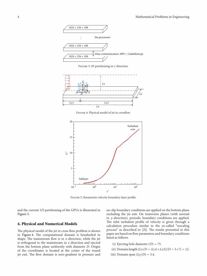
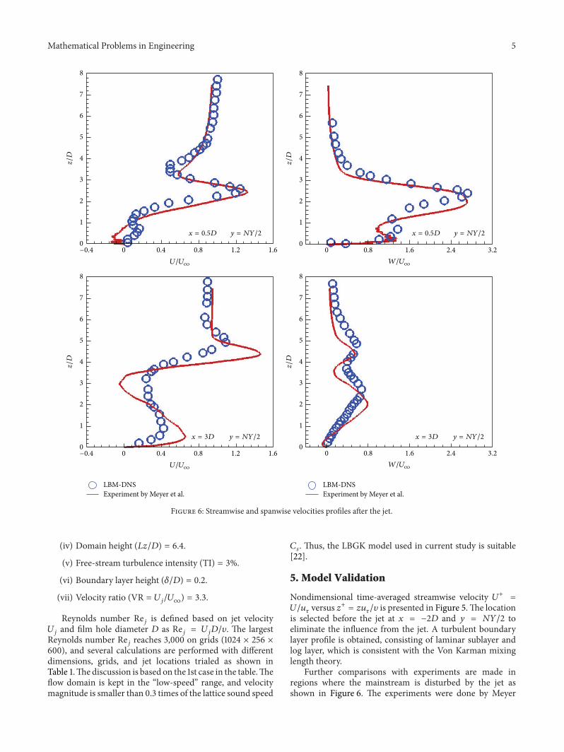
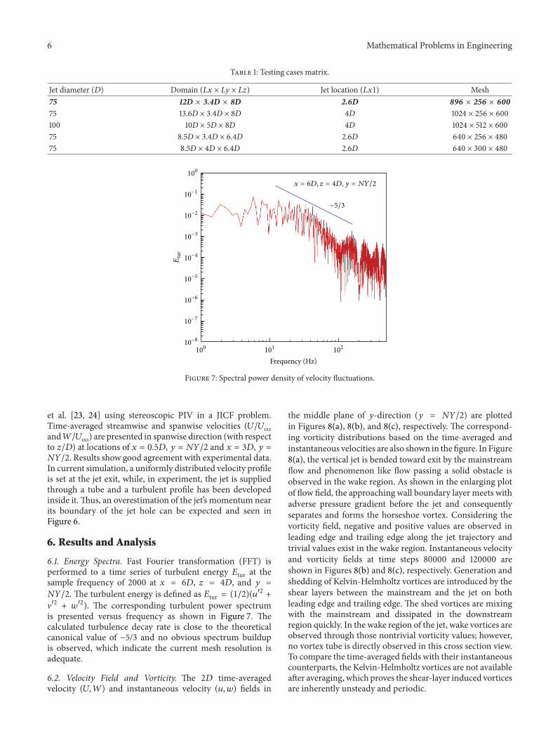
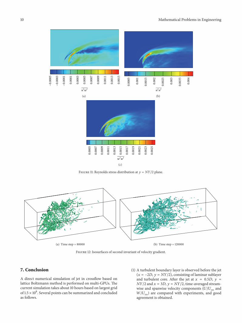
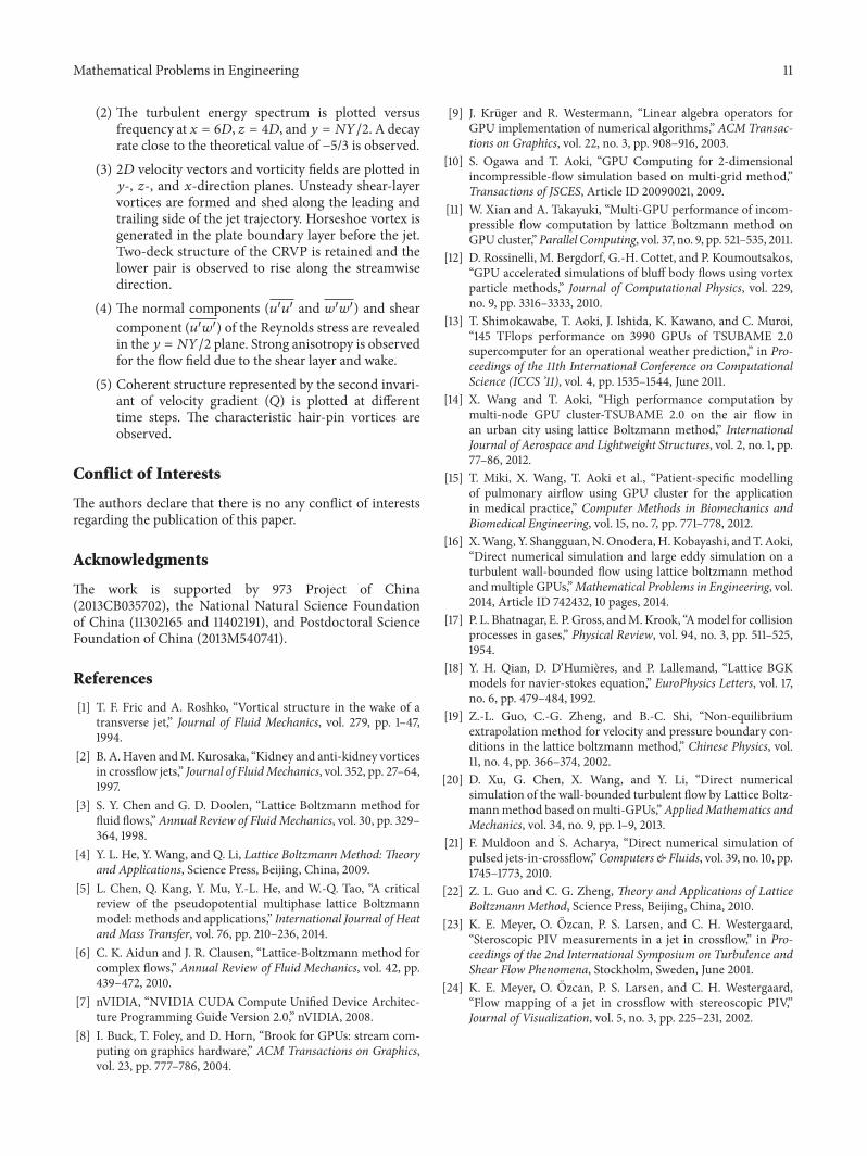