Research Article Effect of Impeller Inlet Geometry on Cavitation...
10
Research Article Effect of Impeller Inlet Geometry on Cavitation Performance of Centrifugal Pumps Based on Radial Basis Function Shuwei Zhang, Renhui Zhang, Sidai Zhang, and Junhu Yang School of Energy and Power Engineering, Lanzhou University of Technology, Lanzhou 730050, China Correspondence should be addressed to Renhui Zhang; [email protected] Received 12 August 2016; Revised 19 October 2016; Accepted 3 November 2016 Academic Editor: Ryoichi Samuel Amano Copyright © 2016 Shuwei Zhang et al. is is an open access article distributed under the Creative Commons Attribution License, which permits unrestricted use, distribution, and reproduction in any medium, provided the original work is properly cited. Aiming at the cavitation problem, the blade leading edge shape has been changed to analyze its impact on the cavitation performance for centrifugal pumps. And the response model has been established based on the Radial Basis Function. e calculation case results show that the leading edge extending forward along the shroud can improve the inlet flow condition and cavitation performance. But the cavitation performance has been reduced immensely when the leading edge extends backward along the shroud. Along with the leading edge which extends forward along the hub, the cavitation performance increases at first and then decreases. A better cavitation performance for centrifugal pumps has lower load of blade inlet and higher pressure of blade suction side. e pressure pulsation is affected by the vortex out of the impeller and the falling-off and collapsing of the cavitation bubbles. e lower the pressure pulsation for blade passing frequency and the second harmonics of the samples is, the better the cavitation performance is. A relatively accurate response model based on the Radial Basis Function has been established to predict the effect of the shape of blade leading edge on the cavitation performance of centrifugal pumps. 1. Introduction Cavitation is very complicated phenomenon that usually appears in the hydraulic machinery. It has serious impact on hydraulic performance and stability of pump. Cavitation will occur when the local pressure of liquid is lower than the vapor pressure. At that time, the vapor bubbles appear, develop, and collapse at high pressure area along with the motion of liquid [1]. In hydraulic machinery, the cavitation is very harmful. It will result in the vibration [2], noise [3, 4], corrosion and damage [5] of flow passage components, performance decline [6] of hydraulic machinery, and so on. In hydraulic machinery, there are many factors affecting the cavitation performance such as impeller inlet diameter, impeller hub diameter, blade inlet angles, shape of blade leading edge, blade passage throat area, blade thickness and number, blade surface roughness, suction chamber passage shape, and inducer shape. At present, aiming at these factors, many meaningful works have been done by researchers of this field. Schiavello and Visser [7] analyzed synthetically all these effect factors on the cavitation of pump and proposed a method to judge the standard of cavitation strength and control the development of bubbles. Wei et al. [8] considered the geometrical parameters of impeller and concluded a practical method to improve the cavitation performance of centrifugal pump. Acosta et al. [9] and Bakir et al. [10] contrasted different sweep angle of inducer blade leading edge and got the inducer blade leading edge with high cavitation performance, though analyzing the appearing and development of different type of cavitation. Balasubramanian et al. [11] contrasted different shape of blade leading edge and proposed that the parabolic blade leading edge will improve the cavitation performance and extend the life expectancy of impeller. Fan et al. [12] concluded that the bulge of blade leading edge towards the entrance direction of impeller is larger, and the cavitation performance of centrifugal pumps is worse. Yang et al. [13] proposed that appropriate extending of blade leading edge towards flow direction can improve the cavitation performance of double suction centrifugal pump effectively. Luo et al. [14] proposed that the flow uniformity of impeller inlet can effectively improve the cavitation performance of centrifugal pump through extend- ing the blade leading edge and increasing the blade inlet angle. Hindawi Publishing Corporation International Journal of Rotating Machinery Volume 2016, Article ID 6048263, 9 pages http://dx.doi.org/10.1155/2016/6048263
-
Upload
truonghuong -
Category
Documents
-
view
219 -
download
0
Transcript of Research Article Effect of Impeller Inlet Geometry on Cavitation...

Research ArticleEffect of Impeller Inlet Geometry on Cavitation Performance ofCentrifugal Pumps Based on Radial Basis Function
Shuwei Zhang Renhui Zhang Sidai Zhang and Junhu Yang
School of Energy and Power Engineering Lanzhou University of Technology Lanzhou 730050 China
Correspondence should be addressed to Renhui Zhang zhangrhlut163com
Received 12 August 2016 Revised 19 October 2016 Accepted 3 November 2016
Academic Editor Ryoichi Samuel Amano
Copyright copy 2016 Shuwei Zhang et al This is an open access article distributed under the Creative Commons Attribution Licensewhich permits unrestricted use distribution and reproduction in any medium provided the original work is properly cited
Aiming at the cavitation problem the blade leading edge shape has been changed to analyze its impact on the cavitation performancefor centrifugal pumps And the responsemodel has been established based on the Radial Basis FunctionThe calculation case resultsshow that the leading edge extending forward along the shroud can improve the inlet flow condition and cavitation performanceBut the cavitation performance has been reduced immensely when the leading edge extends backward along the shroud Alongwiththe leading edge which extends forward along the hub the cavitation performance increases at first and then decreases A bettercavitation performance for centrifugal pumps has lower load of blade inlet and higher pressure of blade suction side The pressurepulsation is affected by the vortex out of the impeller and the falling-off and collapsing of the cavitation bubbles The lower thepressure pulsation for blade passing frequency and the second harmonics of the samples is the better the cavitation performanceis A relatively accurate response model based on the Radial Basis Function has been established to predict the effect of the shapeof blade leading edge on the cavitation performance of centrifugal pumps
1 Introduction
Cavitation is very complicated phenomenon that usuallyappears in the hydraulic machinery It has serious impact onhydraulic performance and stability of pump Cavitation willoccurwhen the local pressure of liquid is lower than the vaporpressure At that time the vapor bubbles appear develop andcollapse at high pressure area along with the motion of liquid[1] In hydraulic machinery the cavitation is very harmfulIt will result in the vibration [2] noise [3 4] corrosion anddamage [5] of flow passage components performance decline[6] of hydraulic machinery and so on
In hydraulic machinery there are many factors affectingthe cavitation performance such as impeller inlet diameterimpeller hub diameter blade inlet angles shape of bladeleading edge blade passage throat area blade thickness andnumber blade surface roughness suction chamber passageshape and inducer shape At present aiming at these factorsmany meaningful works have been done by researchers ofthis field Schiavello and Visser [7] analyzed synthetically allthese effect factors on the cavitation of pump and proposeda method to judge the standard of cavitation strength and
control the development of bubbles Wei et al [8] consideredthe geometrical parameters of impeller and concluded apractical method to improve the cavitation performance ofcentrifugal pump Acosta et al [9] and Bakir et al [10]contrasted different sweep angle of inducer blade leadingedge and got the inducer blade leading edge with highcavitation performance though analyzing the appearing anddevelopment of different type of cavitation Balasubramanianet al [11] contrasted different shape of blade leading edge andproposed that the parabolic blade leading edge will improvethe cavitation performance and extend the life expectancyof impeller Fan et al [12] concluded that the bulge of bladeleading edge towards the entrance direction of impeller islarger and the cavitation performance of centrifugal pumpsis worse Yang et al [13] proposed that appropriate extendingof blade leading edge towards flow direction can improvethe cavitation performance of double suction centrifugalpump effectively Luo et al [14] proposed that the flowuniformity of impeller inlet can effectively improve thecavitation performance of centrifugal pump through extend-ing the blade leading edge and increasing the blade inletangle
Hindawi Publishing CorporationInternational Journal of Rotating MachineryVolume 2016 Article ID 6048263 9 pageshttpdxdoiorg10115520166048263
2 International Journal of Rotating Machinery
The shape of blade leading edge has great effect on thecavitation performance of centrifugal pump In this researchthe response model based on the Radial Basis Function(RBF) method has been proposed to predict the effect ofshape of blade leading edge on the cavitation performanceof centrifugal pump The cavitation flow in the centrifugalpumps is simulatedwith steady andunsteady flowThebubbledistribution in the impeller blade load and the character ofpressure fluctuation in different area of volute are analyzed forthe design of experiments (DOE) samples The approximatemodel between cavitation performance of centrifugal pumpsand the shape of blade leading edge is established using theRadial Basis Function method
2 Radial Basis Function Technology
21 Overview of the RBF TheRadial Basis Function is a kindof approximate interpolation method In 1982 Franke [15]innovatively proposed to interpolate the random points onthe dimensional surface by the RBF method and proved thereliability and accuracy of interpolation Turk and Orsquobrien[16] realized the reconstruction of complicated dimensionalsurface by interpolating the random points and selectingconstraint points reasonably Buhmann [17] proved the con-vergence of the approximate process of RBF method and theuniqueness of approximate solution existence and researchedsome new practical applications
As a kind of interpolation method the essence of RBF isto achieve the new datum fitting by learning from the existingdatum The stability and accuracy have been proved well Ithas strong adaptation facing the complicated problems likehigh dimensions multivariate nonlinear huge amount ofdatum and so on At present the RBF method has been usedin many fields such as surface reconstruction [18ndash21] meshdeformation [22ndash24] optimizationmethod [25 26] and fluidstructure interaction [27]
22 Algorithm of the RBF The formula of RBF is as follows
119891 (119909) =119899
sum119894=1
120582119894120601 (1003817100381710038171003817119909 minus 1199091198941003817100381710038171003817) (1)
where 119899 is the amount of sample points 119909 is the vector ofdesign variable 119909
119894is the vector of design variable at the 119894th
sample point 120601(119903) is the Radial Basis Function 120582119894is the
coefficient at the 119894th Radial Basis Function and 119909minus119909119894 is the
Euclidean norm which is the Euclidean distance between thedesign variable and sample point For the three-dimensionspace it can be expressed as follows
119903 = 1003817100381710038171003817119909 minus 1199091198941003817100381710038171003817 = radic(119909 minus 119909119894)2 + (119910 minus 119910
119894)2 + (119911 minus 119911
119894)2 (2)
The common forms of Radial Basis Function are linear(120601(119903) = 119903) cubic (120601(119903) = 1199033) thin-plate spline (120601(119903) =1199032 ln(119888119903)) Gaussian (120601(119903) = 119890minus1198881199032) inverse multiquadric(120601(119903) = 1radic1199032 + 1198882) and so on
In general the Radial Basis Function can be divided intothree forms global local and compact function [28] The
Table 1 Hydraulic performance parameters
Flowm3h
Headm
Rotate speedrmin
Efficiency
NPSHrm
120 6109 2900 73 486200 5235 2900 824 451240 4534 2900 797 532
Gaussian form belongs to the global function that the inter-polation is dependent on all data points And it is the strongnonlinear function which has a strong generalization abilityand can adapt nonlinear problem perfectly The advantage ofthe Gaussian has been proved in the interpolation of complexsurface [29] So the Gaussian has been used in this researchof which expression is
120601 (119903) = 119890minus1198881199032 (3)
where 119888 is a positive real number and 0 le 119888 le 1At first a group of sample points 119883 = 119883
1 1198832 119883
119899
have been given in the Euclidean space The correspondingfunction solutions are 119891(119909) = 119891
1 1198912 119891
119899 The corre-
sponding RBF coefficients 120582119894= 120582
1 1205822 120582
119899 at every
sample points can be got by (1) Then the datum in the rangeof existing space can be predicted by interpolating the datumbetween every sample points according to (1)
The error must be considered in the response model andthe adjusted coefficient of multiple determinations 1198772adj andthe root mean square error RMSE are taken as the importantreference where the range of 1198772adj is from 0 to 1 and the fittingaccuracy is higher when 1198772adj is close to 1
3 Design of Experiments andthe Numerical Simulation
31 Design of Experiments In this paper the investigatedprototype pump is M128ndash200 single-stage and single-suctioncentrifugal pumpThe hydraulic performance parameters aregiven in Table 1
In order to investigate the effect of the shape of bladeleading edge on the cavitation performance the blade leadingedge is parameterized to get design of experiments sampleswhile the meridian shape of impeller remains unchanged
In the meridian plane the blade leading edge is extendedalong the shroud towards the direction of impeller entrancewhich is called the blade leading edge forward-sweep (FS)along the shroud And the blade leading edge is extendedalong the shroud towards the direction of impeller exit whichis called the blade leading edge back-sweep (BS) along theshroud So the other two situations are respectively calledthe blade leading edge FS along the hub and the blade leadingedge BS along the hub The specific details are given inFigure 1
In this research the shape of the blade leading edge isparameterized by introducing the perturbation of the controlvariable FS and BS on shroud and hub These perturba-tions are based on the prototype design The parameter
International Journal of Rotating Machinery 3
Shroud
BS along the shroud
FS along the shroud
Origin leading edge
Hub
BS along the hub
FS along the hub
Figure 1 Sketch of blade leading edge positionrsquos change
set (plusmn119904ℎ119903119900119906119889 plusmnℎ119906119887) is used to parameterize the centrifugalpump blade leading edge In this set shroud and hub rep-resent respectively the angle of blade leading edge movingalong the shroud and hub The positive and negative repre-sent respectively the FS andBSThe central composite designis implemented according to the parameter set The designof experiments is as follows (0∘ 0∘) (plusmn10∘ 0∘) (plusmn20∘ 0∘)(0∘ plusmn10∘) and (0∘ plusmn20∘)
32 Numerical Simulation The volumetric and disc fric-tion losses are estimated using the experiential methodThe computational domain includes section pipe impellervolute and discharge pipe Every computational domain isdiscretized and the grids are closed at near wall area Thegrid independency test which makes the change of hydraulicperformance parameters within 05 is implemented and thegrid number is 15 million
The pump internal flow field is simulated using commer-cial software Fluent The velocity and pressure are coupledby using SIMPLEC algorithm The SST 120581-120596 turbulent modeland the Zwart-Gerber-Belamri cavitation model are usedThe average cavitation bubble diameter is 2 times 10minus6m and thesaturated vapor pressure is 3540 Pa
Firstly the noncavitation flow in centrifugal pump issimulated and then the steady cavitation simulation is on thebasis of that result The cavitation flow in centrifugal pumpis simulated by reducing the pressure at pump inlet Alongwith the decrease of inlet pressure cavitation is aggravatedin centrifugal pump and that leads to the decrease of everyhydraulic performance parameterThe corresponding cavita-tionmarginNPSHa is taken as the required cavitationmarginNPSHrwhen the head declines about 3The results of steadynumerical simulation are taken as the initial value of unsteadynumerical simulation Time of centrifugal pump impellerrotating a circle is assumed as TThe time of impeller rotating3∘ is taken as a time step so Δ119879 = 119879120 = 000017241 s
The hydraulic performance comparison between exper-iment and CFD result is presented in Figure 2 They matchpreferably
4 Results and Discussion
41 Analysis of Impeller Internal Flow Field Along with thedecrease of pressure cavitation appears and is aggravated
50
60
70
Requ
ired
cavi
tatio
n m
argi
n (m
)
Effici
ency
()80
90
9
12
15
120 140 160 180 200 220 24030
40
Hea
d (m
)
60
70
0
3
6
Flow (m3h)
NPSHrCFD
120578CFD
HCFD NPSHrexperiment
120578experiment
Hexperiment
Figure 2 Hydraulic performance comparison between experimentand numerical simulation
gradually in centrifugal pumpThe cavitation bubbles initiallyappear at low pressure area of impeller which locates theblade suction side leading edge near shroud When thecavitation is aggravated bubbles extend gradually towardsimpeller outlet along the blade The range of cavitation areabecomes wider and extends towards blade pressure sideTherefore the impeller passageway is blocked partly thatmakes the fluid get through the cavitation area quickly Dueto the enlarging of passageway behind the cavitation areathe velocity of fluid declines and results in that vortex formsat this area In addition the pressure difference betweenpressure side and suction side makes the vortex area stableThe cavitation performance curves of the blade samples areshown in Figure 3
In Figure 3 when the inlet pressure is high that is thenoncavitation state and the head is unaffected Along withthe decrease of pressure cavitation appears and is aggravatedgradually in centrifugal pump which leads to the decrease ofthe headWhen the inlet pressure is lower enough completelycavitation state is in the centrifugal pump and the head dropssteeply
Blade FS along the shroud can promote the head andefficiency slightly and get better cavitation performanceThenblade BS along the shroud reduces the head efficiency andcavitation performance all But the blades FS and BS alongthe hub can respectively promote and reduce the head andefficiency and they all have slight effect on the cavitationperformance
When the angle of blades FS and BS along the shroud andhub is different the corresponding cavitation performance isrelatively differentThedistribution of bubbles at themidspanis shown in Figure 4 when NPSHa is 331m
As shown in Figure 4 the cavitation performance ofcentrifugal pump is greatly affected when the position ofblade leading edge changes at the shroudThe blade FS alongthe shroud can observably reduce the range of cavitation areain impeller Because pressure at blade suction side leadingedge near the shroud is low relatively the bubbles appearat that area The fluid entering impeller gets the energyfrom blade when the blade leading edge is FS along the
4 International Journal of Rotating Machinery
52
2 4 6 8 10 12 1442
44
46
48
50
Hea
d (m
)
NPSHa (m)
(0∘ 0∘)(minus10∘ 0∘)(minus20∘ 0∘)
(10∘ 0∘)(20∘ 0∘)
(a) Shroud
50
52
2 4 6 8 10 12 14
38
40
42
44
46
48
Hea
d (m
)
NPSHa (m)
(0∘ 0∘)(0∘ minus10∘)(0∘ minus20∘)
(0∘ 10∘)(0∘ 20∘)
(b) Hub
Figure 3 Cavitation performance curves of blade samples
(20∘ 0∘)(10∘ 0∘)(minus20∘ 0∘) (minus10∘ 0∘) (0∘ 0∘)
(0∘ 20∘)(0∘ 10∘)(0∘ minus20∘) (0∘ minus10∘) (0∘ 0∘)
0000e + 0006764e minus 0021353e minus 0012029e minus 0012706e minus 0013382e minus 0014058e minus 0014735e minus 0015411e minus 0016088e minus 0016764e minus 0017440e minus 0018117e minus 0018793e minus 0019470e minus 001
Wat
er v
apor
vol
ume f
ract
ion
0000e + 0006764e minus 0021353e minus 0012029e minus 0012706e minus 0013382e minus 0014058e minus 0014735e minus 0015411e minus 0016088e minus 0016764e minus 0017440e minus 0018117e minus 0018793e minus 0019470e minus 001
Wat
er v
apor
vol
ume f
ract
ion
Figure 4 Distribution of bubbles at midspan when NPSHa is 331m
shroud The pressure at this area is promoted and the flowcondition is improved at impeller entrance So the cavitationperformance is promoted On the contrary the blade BSalong the shroud reduces cavitation performance greatlyHowever the position of blade leading edge near the hubhas slight effect on the cavitation performance of centrifugalpump The distribution of bubbles at midspan changes littlewhen the FS angle is small But the bubbles area is enlargedapparently when the FS angle is large as the impeller entrancepassageway is blocked seriously by the oversize blade FS anglealong the hub The flow uniformity is destroyed that leadsthe decline of cavitation performance while the blade BSalong the hub has slight effect on the distribution of bubblesat midspan and the distribution area of bubbles is enlargedalong with the increase of BS angle
In addition due to the asymmetry of volute passage-way the coupling between impeller and volute makes the
asymmetry of blade surface pressure distribution Conse-quently the distribution of bubbles in each impeller passage-way is asymmetric which is related to the relative positionbetween blade and the tongue
42 Analysis of Blade Load Distribution The pressurebetween pressure side (PS) and suction side (SS) of sameblade at same radius is taken as the blade load The bladeload distribution of different blade leading edge at midspanis shown in Figure 5
The original blade load distribution is shown in Fig-ure 5(a) The pressure change of pressure side is complicatedThere is a pressure minimum at relative position 008 behindthe blade entrance It can be interpreted as that the boundarylayer separation occurs around that place [30] The pressureof suction side increases gradually Along with the declineof inlet pressure the pressure of pressure and suction side
International Journal of Rotating Machinery 5
Noncavitation PSNoncavitation SS
02 04 06 08 1000xX
0
1
2
3
4
5
6p
(105
Pa)
NPSHa = 576m PS
NPSHa = 576m SSNPSHa = 331m PSNPSHa = 331m SS
(a) Original blade
02 04 06 08 1000xX
0
1
2
3
4
5
6
p(105
Pa)
(0∘ 0∘) PS(0∘ 0∘) SS (minus20∘ 0∘) PS
(minus20∘ 0∘) SS(20∘ 0∘) PS
(20∘ 0∘) SS
(b) Blades FS and BS 20∘ along the shroud at noncavitation state
02 04 06 08 1000xX
0
1
2
3
4
5
6
p(105
Pa)
(0∘ 0∘) PS(0∘ 0∘) SS(0∘ 20∘) PS
(0∘ 20∘) SS(0∘ minus20∘) PS(0∘ minus20∘) SS
(c) Blades FS and BS 20∘ along the hub at noncavitation state
02 04 06 08 1000xX
0
1
2
3
4
5
6p
(105
Pa)
(0∘ 0∘) PS(0∘ 0∘) SS(0∘ 10∘) PS
(0∘ 10∘) SS(0∘ 20∘) PS(0∘ 20∘) SS
(d) Blade FS along the hub at noncavitation state
Figure 5 Blade load distribution of different blade leading edge at midspan
declines The pressure at the area which is covered bycavitation bubbles is almost zero So the degree of cavitationon the blade can be judged by the distribution of bladeload
As shown in Figure 5(b) the blade FS along the shroudleads to the decline of pressure on pressure side and thedecline degree is larger at front and central part of bladeComparing with the original blade the pressure on suctionside is lower partially at central and rear part of blade butis higher at the entrance When the pressure at centrifugalpump entrance declines the probability of bubbles generatingon the original blade is higher than the FS blade alongthe shroud So the cavitation performance of centrifugal isimproved greatly The pressure on pressure side is almost thesame at the front of blade and low at the central and rear of
blade when the blade is BF along the shroudThe pressure onthe suction side declines apparently especially at the entrancethat leads to a bad cavitation performance
In Figure 5(c) the pressure on the pressure side at thefront and central part of blade declines apparently but it isalmost the same at the rear of blade when the blade is FSalong the hub So the change of cavitation performance is notobvious When the blade is BS along the hub the pressureon the suction side at the entrance is lower than the originalblade So the cavitation performance of it is bad As shown inFigure 5(d) appropriate FS angle along the hub can improvethe cavitation performance slightly
Therefore the cavitation performance can be judgedby the blade load distribution at midspan in the state ofnoncavitation
6 International Journal of Rotating Machinery
P1
P2
P3
P4
P5
P6
P7
P8P9
P10
Figure 6 Distribution of monitoring points in the volute
P1 P2 P3 P4 P5 P6 P7 P8 P9 P10
Point
125000
100000
75000
50000
25000
0
Am
plitu
de (P
a)
Figure 7 Pressure pulsation amplitude of points in volute
43 Analysis of Pressure Pulsation in Volute The pressurepulsation generates in centrifugal pump because of the asym-metry of volute passageway and the rotor-stator interactionsbetween impeller and volute In the state of cavitation thedevelopment and collapse of cavitation bubbles have effect onthe pressure pulsation in the centrifugal pump
10 monitoring points are set up to monitor the pressurepulsation in the flow field of volute as shown in Figure 6Thepressure pulsation amplitude of points in volute is shown inFigure 7 which presents that the tongue (Point 119875
9) has great
effect on the pressure pulsation of the voluteThemaximum pressure pulsation amplitude is 100726 Pa
which occurred at the tongue The strength of pressurepulsation is related to the relative distance of tongue Thepressure pulsation near the tongue is stronger than otherareas because of the asymmetry of volute passageway So therotor-stator interaction is most intensive and the fluid is mostrestricted at the tongue Excitation produced by pressurepulsation at the tongue has great effect on the vibration andnoise of centrifugal pump and along with the developmentof cavitation degree the effect is conspicuous [31] Thereforein this paper the pressure pulsation at the tongue (Point 119875
9)
is considered when NPSHa is 331m
Table 2 Maximum pressure pulsation amplitude of different bladesamples at 119875
9
Blade samples Maximum pressurepulsation (Pa)
Reduction()
(0∘ 0∘) 100726(minus10∘ 0∘) 104695 minus394(minus20∘ 0∘) 327479 minus22512(+10∘ 0∘) 81347 1924(+20∘ 0∘) 74595 2594
The FS and BS blades along the shroud have greaterinfluence on the pressure pulsation than the FS and BS bladesalong the hubThe influence is shown inTable 2That presentsthat the FS blade along the shroud can obviously reduce themaximum pressure pulsation amplitude at the tongue
The pressure pulsation at 1198759of different samples is
converted to the pressure signal in the frequency domain bythe Fast Fourier Transform as is shown in Figure 8There arespikes of the pressure pulsation amplitude which are affectedby the times of rotation frequency blade passing frequencyand their harmonic frequenciesThe blade passing frequencyis 290Hz as the rotate speed of impeller is 2900 rmin and theblade number is 6 As shown in Figure 8 the blade passingfrequency is the main factor to affect the pressure pulsationAnd along with the aggravating of the cavitation degree thepressure pulsation amplitude of blade passing frequency andsecond harmonics of the blade frequency also increases
As shown in Figure 8(a) comparing to the original bladethe pressure pulsation amplitude of the FS blade along theshroud is lower that gets a stable cavitation performanceOn the contrary along with the increase of BS angle alongthe shroud the pressure pulsation is more aggravated WhenNPSHa is 331m internal centrifugal pump is on the full-cavitation conditionThe bubbles range is wide therefore thepassageway is blocked and the fluid is disturbed in impellerSo the flow state is chaos from blade leading edge to thetrailing edge That can obviously affect the fluid enteringthe volute and lead to the generation of vortex So that haseffect on the pressure pulsation in volute And the normalpressure pulsation in centrifugal pump is also disturbed bythe falling-off and collapsing of bubbles So these two reasonsmake the difference between the pressure pulsations of thesesamplesThe FS and BS blades along the shroud have obviouseffect on the pulsation pressure in volute So the (0∘ 0∘) and(plusmn20∘ 0∘) samples are compared emphatically The vorticitydistributions of the 3 samples are presented in Figure 9 Thevortex can be reflected by the strength of vorticity whichpresents the rotation of fluid velocity vector The (+20∘ 0∘)sample can obviously reduce the strength of vorticity nearthe tongue as shown in Figure 9 So the FS blade along theshroud can make a lower pressure pulsation and get a bettercavitation performance than other samples
Similar to Figure 8(a) Figure 8(b) also shows that theamplitude of the pressure pulsation can reflect the cavitationperformance Along with the increasing of FS angle alongthe hub the pressure pulsation amplitude firstly reduces and
International Journal of Rotating Machinery 7
(0∘ 0∘)(minus10∘ 0∘)
(minus20∘ 0∘)
(10∘ 0∘)(20∘ 0∘)
100
80
60
40
20
0
p(k
Pa)
0 300 600
f (Hz)900 1200 1500
(a) The blades FS and BS along the shroud
(0∘ 0∘)(0∘ minus10∘)
(0∘ minus20∘)
(0∘ 10∘)(0∘ 20∘)
100
80
60
40
20
0
p(k
Pa)
0 300 600
f (Hz)900 1200 1500
(b) The blades FS and BS along the hub
Figure 8 Frequency domain of pressure pulsation at 1198759when NPSHa is 331m
0000e + 000
3448e + 002
6897e + 002
1034e + 003
1379e + 003
1724e + 003
2069e + 003
2414e + 003
2759e + 003
3103e + 003
3448e + 003
3793e + 003
4138e + 003
4483e + 003
4828e + 003
Vort
icity
(sminus1)
(+20∘ 0∘)(0∘ 0∘)(minus20∘ 0∘)
Figure 9 Vorticity distributions of the pump at midspan when NPSHa is 331m
then rises Because the FS and BS along the hub have slighteffect on the flow state at impeller entrance the distributionof vortex is almost the same with the (0∘ 0∘) sample So thecavitation performance is slightly affected by the positionalong the hub
5 The Radial Basis Function Response Modelfor Cavitation Performance
In this research the effect of blade leading edge shapeon cavitation performance is predicted by the Radial BasisFunction Within a certain range the more the samples arethe more accurate the response model is The sweep anglealong the shroud and the hub is taken as the design variableand the required cavitation margin NPSHr of centrifugalpump is taken as the response value The RBF method andthe DOE are introduced in detail in Sections 2 and 3 TheRadial Basis Function response model is constructed usingMATLAB code The results of response model are shown inFigure 10
To verify the accuracy of the approximate model thecomparison of the Radial Basis Function response resultswith the CFD results is shown in Table 3
5
4
3
2
NPS
Hr (
m)
minus20
minus10
0 0
10
20 minus20
minus10
10
20
Shroud ( ∘) Hub (∘ )
Figure 10 Cavitation performance response model by Radial BasisFunction
As shown in Table 3 the maximal relative predicted erroris 6888The adjusted coefficient of multiple determination1198772adj = 08269 and the root mean square error RMSE =
8 International Journal of Rotating Machinery
Table 3 Comparisons of RBF response model results and CFDresults
Predictedpoint
CFD resultm
RBF responsemodel result
m
Error
(5∘ minus5∘) 29498 27741 5896(minus5∘ 5∘) 32061 31243 2551(15∘ 5∘) 26011 24223 6874(5∘ 15∘) 28893 29698 2786(minus15∘ minus5∘) 38245 39569 3462(minus10∘ minus20∘) 40259 43032 6888
01306 The proposed RBF response model is relativelyaccurate and the effect of blade leading edge position on thecavitation performance for centrifugal pump can be reflectedaccurately
6 Conclusions
(i) In this research the effect of the different blade lead-ing edge shape on pump cavitation performance isinvestigated The flow entering impeller has receivedthe energy in advance due to the FS blade along theshroud The flow state at the impeller entrance isimproved so the cavitation performance is improvedThe position of blade leading edge along the hubhas slight effect on cavitation performance of cen-trifugal pump The appropriate FS angle along thehub can improve the cavitation performance slightlybut when the FS angle along the hub is oversizethe entrance is blocked seriously and the cavitationperformance is reduced
(ii) The cavitation performance can be judged by theblade load distributionThe lower the blade load nearthe inlet is and the higher the pressure at the suctionside is the better the cavitation performance is
(iii) Along with the decrease of the cavitation perfor-mance the blade passing frequency and the secondharmonics of blade passing frequency in volute aremore drastic due to the vortex out of the impeller andthe falling-off and collapsing of the bubbles The stateof the cavitation can be reflected by the strength ofthe pressure pulsationThe FS blade along the shroudhas low strength of vorticity and low amplitude ofthe pressure pulsation in volute which has bettercavitation performance than other blade samples
(iv) The cavitation performance response model based onthe Radial Basis Function is established The sweepangle along the shroud and the hub is taken as thedesign variable and the required cavitation marginNPSHr of centrifugal pump is taken as the responsevalue The response model is relative accurate Theeffect of the shape of blade leading edge on thecavitation performance of centrifugal pump can beaccurately predicted
Competing Interests
The authors declare that they have no competing interests
Acknowledgments
The research is supported by National Natural ScienceFund of China (Grant no 51469014) and National KeyResearch and Development Program of China (Grant no20016YFB0200901) The supports are gratefully acknowl-edged
References
[1] C E BrennenHydrodynamics of Pumps Cambridge UniversityPress New York NY USA 2011
[2] T Rus M Dular B Sirok M Hocevar and I Kern ldquoAninvestigation of the relationship between acoustic emissionvibration noise and cavitation structures on a Kaplan turbinerdquoJournal of Fluids Engineering vol 129 no 9 pp 1112ndash1122 2007
[3] S F Chini H Rahimzadeh and M Bahrami ldquoCavitationdetection of a centrifugal pump using noise spectrumrdquo in Pro-ceedings of the ASME International Design Engineering TechnicalConferences and Computers and Information in EngineeringConference (DETC rsquo05) pp 13ndash19 American Society ofMechan-ical Engineers Long Beach Calif USA September 2005
[4] S Christopher and S Kumaraswamy ldquoIdentification of criticalnet positive suction head from noise and vibration in a radialflow pump for different leading edge profiles of the vanerdquoJournal of Fluids Engineering vol 135 no 12 Article ID 1213012013
[5] C E Brennen ldquoA review of the dynamics of cavitating pumpsrdquoJournal of Fluids Engineering Transactions of the ASME vol 135no 6 Article ID 061301 2013
[6] Y A Bouziad Physical Modelling of Leading Edge CavitationComputational Methodologies and Application to HydraulicMachinery Universite Paris VI Paris France 2006
[7] B Schiavello and F C Visser ldquoPump cavitationmdashvariousNPSHr criteria NPSHa margins and impeller life expectancyrdquoin Proceedings of the 25th International Pump Users SymposiumTurbomachinery Laboratory Texas AampM University CollegeStation pp 113ndash144 Houston Tex USA February 2009
[8] Z P Wei H P Wan S J Xu et al ldquoThe analysis of effect fac-tors on cavitation performance for centrifugal pumprdquo GeneralMachinery no 4 pp 86ndash88 2011
[9] A J Acosta Y Tsujimoto Y Yoshida S Azuma and P CooperldquoEffects of leading edge sweep on the cavitating characteristicsof inducer pumpsrdquo International Journal of Rotating Machineryvol 7 no 6 pp 397ndash404 2001
[10] F Bakir S Kouidri R Noguera and R Rey ldquoExperimentalanalysis of an axial inducer influence of the shape of the bladeleading edge on the performances in cavitating regimerdquo Journalof Fluids Engineering vol 125 no 2 pp 293ndash301 2003
[11] R Balasubramanian S Bradshaw and E Sabini ldquoInfluenceof impeller leading edge profiles on cavitation and suctionperformancerdquo in Proceedings of the 27th International PumpUsers Symposium pp 12ndash15 Houston Tex USA September2011
[12] Z L Fan W G Li and J X Xue ldquoThe influence of the shapeof blade inlet edge on NPSH of centrifugal pumprdquo Journal ofGansu University of Technology vol 20 no 1 pp 44ndash47 1994
International Journal of Rotating Machinery 9
[13] J H Yang Y Wang B Guo et al ldquoResearch on influenceof blade inlet position of double-suction pump performancerdquoFluid Machinery vol 41 no 1 pp 49ndash52 2013
[14] X W Luo Y Zhang J Peng H Xu and W Yu ldquoImpeller inletgeometry effect on performance improvement for centrifugalpumpsrdquo Journal of Mechanical Science and Technology vol 22no 10 pp 1971ndash1976 2008
[15] R Franke ldquoScattered data interpolation tests of somemethodsrdquoMathematics of Computation vol 38 no 157 pp 181ndash200 1982
[16] G Turk and J F Orsquobrien Variational Implicit Surface GeorgiaInstitute of Technology 1999
[17] M D Buhmann ldquoRadial basis functionsrdquo Acta Numerica vol9 pp 1ndash38 2000
[18] B S Morse T S Yoo P Rheingans et al ldquoInterpolating implicitsurfaces from scattered surface data using compactly supportedradial basis functionsrdquo in Proceedings of the InternationalConference on Shape Modeling and Applications pp 89ndash98Cambridge Mass USA June 2005
[19] R J Pan X X Meng and T K Whangbo ldquoHermite variationalimplicit surface reconstructionrdquo Science in China Series FInformation Sciences vol 52 no 2 pp 308ndash315 2009
[20] N Kojekine V Savchenko and I Hagiwara ldquoSurface recon-struction based on compactly supported radial basis functionsrdquoin Geometric Modeling Techniques Applications Systems andTools pp 217ndash231 Springer Amsterdam The Netherlands2004
[21] S J Liu and X R Liu ldquoFast Hermite radial basis functionsurface reconstructionrdquo Science China vol 44 no 11 pp 1409ndash1421 2014
[22] Y Sun X G Deng G X Wang Y Wang and M MaoldquoImprovement on Delaunay graph mapping dynamic gridmethod based on radial basis functionsrdquo Acta Aeronautica etAstronautica Sinica vol 35 no 3 pp 727ndash735 2014
[23] L Xie M Xu B Zhang and X-M An ldquoSpace points reductionin grid deforming method based on radial basis functionsrdquoJournal of Vibration and Shock vol 32 no 10 pp 141ndash145 2013
[24] G Wang B Q Lei and Z Y Ye ldquoAn efficient deformationtechnique for hybrid unstructured grid using radial basisfunctionsrdquo Journal of Northwestern Polytechnical University vol29 no 5 pp 783ndash788 2011
[25] E Acar ldquoOptimizing the shape parameters of radial basisfunctions an application to automobile crashworthinessrdquo Pro-ceedings of the Institution of Mechanical Engineers Part DJournal of Automobile Engineering vol 224 no 12 pp 1541ndash1553 2010
[26] S B YaoD LGuo andGWYang ldquoAerodynamic optimizationof high-speed train based on RBF mesh deformationrdquo ChineseJournal of Theoretical and Applied Mechanics vol 45 no 6 pp982ndash986 2013
[27] B Su Q-Y Shi and R-J Qian ldquoPreliminary study on the useof radial basis function in fluid-structure interaction analysisrdquoEngineering Mechanics vol 30 no 1 pp 59ndash63 2013
[28] Y Z Lin B Chen and X Xu ldquoNumerical method of aeroelas-ticity based on radial basis function interpolationrdquo Journal ofBeijing University of Aeronautics and Astronautics vol 40 no 7pp 953ndash958 2014
[29] H B Fang and M F Horstemeyer ldquoGlobal response approxi-mation with radial basis functionsrdquo Engineering Optimizationvol 38 no 4 pp 407ndash424 2006
[30] Y Wang H L Liu S Q Yuan M Tan and K Wang ldquoCFDsimulation on cavitation characteristics in centrifugal pumprdquo
Journal of Drainage and Irrigation Machinery Engineering vol29 no 2 pp 99ndash103 2011
[31] B Gao X Sun M Yang and N Zhang ldquoCharacteristics ofunsteady excitation induced by cavitating flow in centrifugalpumpsrdquo Journal of Mechanical Engineering vol 50 no 16 pp199ndash205 2014
International Journal of
AerospaceEngineeringHindawi Publishing Corporationhttpwwwhindawicom Volume 2014
RoboticsJournal of
Hindawi Publishing Corporationhttpwwwhindawicom Volume 2014
Hindawi Publishing Corporationhttpwwwhindawicom Volume 2014
Active and Passive Electronic Components
Control Scienceand Engineering
Journal of
Hindawi Publishing Corporationhttpwwwhindawicom Volume 2014
International Journal of
RotatingMachinery
Hindawi Publishing Corporationhttpwwwhindawicom Volume 2014
Hindawi Publishing Corporation httpwwwhindawicom
Journal ofEngineeringVolume 2014
Submit your manuscripts athttpwwwhindawicom
VLSI Design
Hindawi Publishing Corporationhttpwwwhindawicom Volume 2014
Hindawi Publishing Corporationhttpwwwhindawicom Volume 2014
Shock and Vibration
Hindawi Publishing Corporationhttpwwwhindawicom Volume 2014
Civil EngineeringAdvances in
Acoustics and VibrationAdvances in
Hindawi Publishing Corporationhttpwwwhindawicom Volume 2014
Hindawi Publishing Corporationhttpwwwhindawicom Volume 2014
Electrical and Computer Engineering
Journal of
Advances inOptoElectronics
Hindawi Publishing Corporation httpwwwhindawicom
Volume 2014
The Scientific World JournalHindawi Publishing Corporation httpwwwhindawicom Volume 2014
SensorsJournal of
Hindawi Publishing Corporationhttpwwwhindawicom Volume 2014
Modelling amp Simulation in EngineeringHindawi Publishing Corporation httpwwwhindawicom Volume 2014
Hindawi Publishing Corporationhttpwwwhindawicom Volume 2014
Chemical EngineeringInternational Journal of Antennas and
Propagation
International Journal of
Hindawi Publishing Corporationhttpwwwhindawicom Volume 2014
Hindawi Publishing Corporationhttpwwwhindawicom Volume 2014
Navigation and Observation
International Journal of
Hindawi Publishing Corporationhttpwwwhindawicom Volume 2014
DistributedSensor Networks
International Journal of
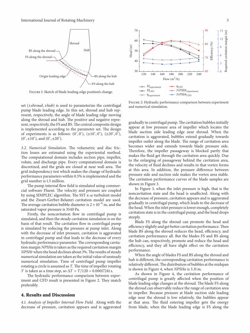
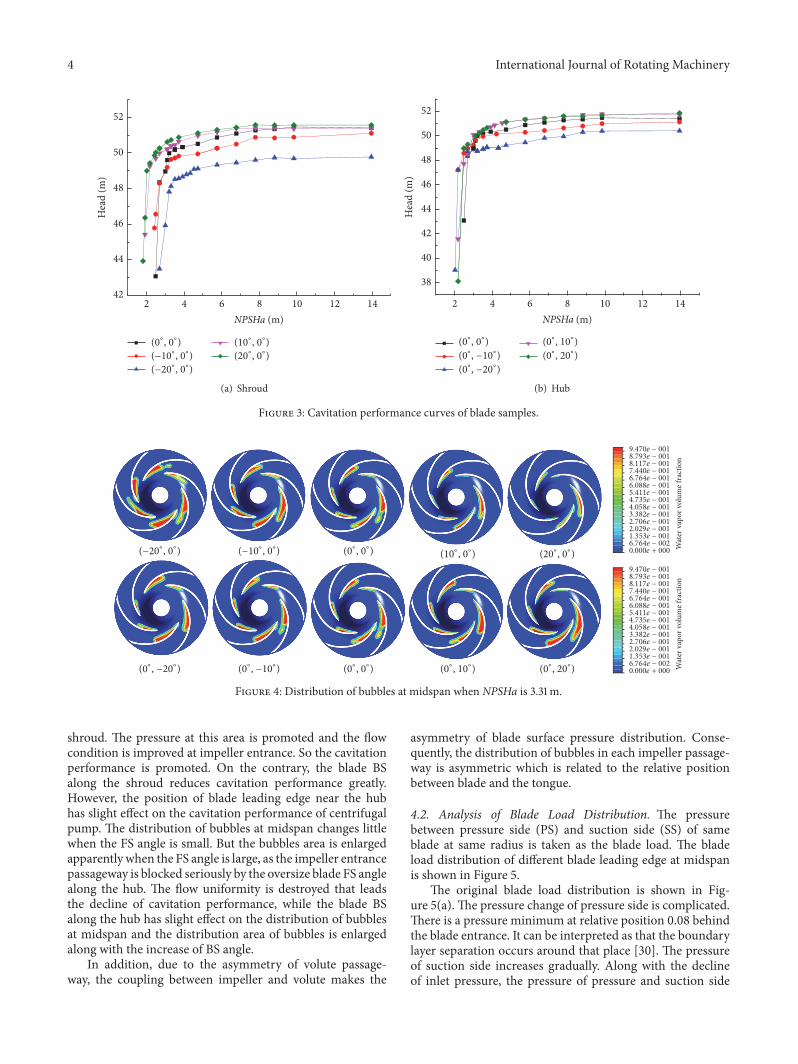
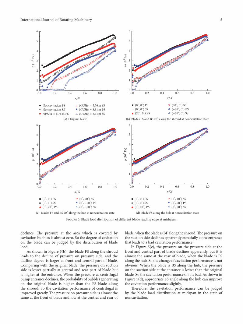
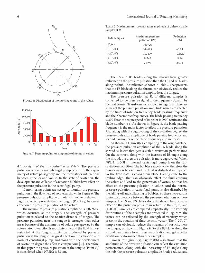
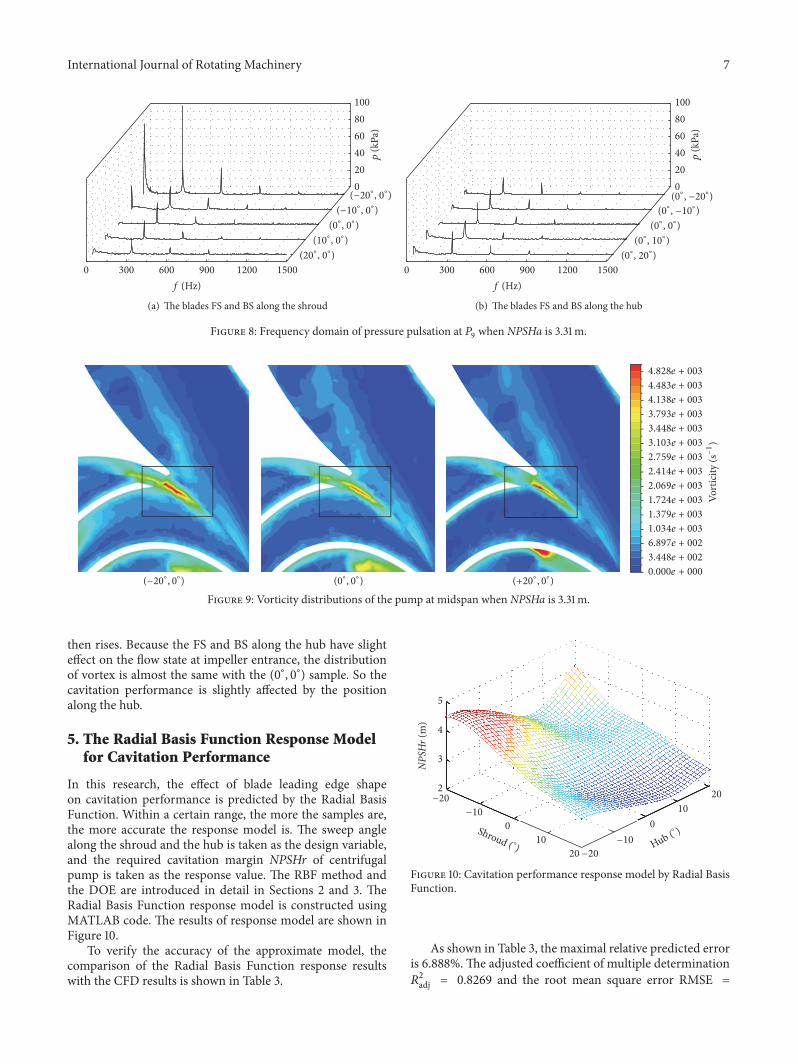

International Journal of
AerospaceEngineeringHindawi Publishing Corporationhttpwwwhindawicom Volume 2014
RoboticsJournal of
Hindawi Publishing Corporationhttpwwwhindawicom Volume 2014
Hindawi Publishing Corporationhttpwwwhindawicom Volume 2014
Active and Passive Electronic Components
Control Scienceand Engineering
Journal of
Hindawi Publishing Corporationhttpwwwhindawicom Volume 2014
International Journal of
RotatingMachinery
Hindawi Publishing Corporationhttpwwwhindawicom Volume 2014
Hindawi Publishing Corporation httpwwwhindawicom
Journal ofEngineeringVolume 2014
Submit your manuscripts athttpwwwhindawicom
VLSI Design
Hindawi Publishing Corporationhttpwwwhindawicom Volume 2014
Hindawi Publishing Corporationhttpwwwhindawicom Volume 2014
Shock and Vibration
Hindawi Publishing Corporationhttpwwwhindawicom Volume 2014
Civil EngineeringAdvances in
Acoustics and VibrationAdvances in
Hindawi Publishing Corporationhttpwwwhindawicom Volume 2014
Hindawi Publishing Corporationhttpwwwhindawicom Volume 2014
Electrical and Computer Engineering
Journal of
Advances inOptoElectronics
Hindawi Publishing Corporation httpwwwhindawicom
Volume 2014
The Scientific World JournalHindawi Publishing Corporation httpwwwhindawicom Volume 2014
SensorsJournal of
Hindawi Publishing Corporationhttpwwwhindawicom Volume 2014
Modelling amp Simulation in EngineeringHindawi Publishing Corporation httpwwwhindawicom Volume 2014
Hindawi Publishing Corporationhttpwwwhindawicom Volume 2014
Chemical EngineeringInternational Journal of Antennas and
Propagation
International Journal of
Hindawi Publishing Corporationhttpwwwhindawicom Volume 2014
Hindawi Publishing Corporationhttpwwwhindawicom Volume 2014
Navigation and Observation
International Journal of
Hindawi Publishing Corporationhttpwwwhindawicom Volume 2014
DistributedSensor Networks
International Journal of