Research Article Dynamic Characteristics and Experimental ...
12
Research Article Dynamic Characteristics and Experimental Research of Dual-Rotor System with Rub-Impact Fault Hongzhi Xu, Nanfei Wang, Dongxiang Jiang, Te Han, and Dewang Li State Key Laboratory of Control and Simulation of Power System and Generation Equipment, Department of ermal Engineering, Tsinghua University, Beijing 100084, China Correspondence should be addressed to Nanfei Wang; [email protected] Received 13 June 2016; Accepted 1 August 2016 Academic Editor: Nuno M. Maia Copyright © 2016 Hongzhi Xu et al. is is an open access article distributed under the Creative Commons Attribution License, which permits unrestricted use, distribution, and reproduction in any medium, provided the original work is properly cited. Rub-impact fault model for dual-rotor system was further developed, in which rubbing board is regarded as elastic sheet. Sheet elastic deformation, contact penetration, and elastic damping support during rubbing of sheet and wheel disk were considered. Collision force and friction were calculated by utilizing Hertz contact theory and Coulomb model and introducing nonlinear spring damping model and friction coefficient. en kinetic differential equations of rub-impact under dry rubbing condition were established. Based on one-dimensional finite element model of dual-rotor system, dynamic transient response of overall structure under rub-impact existing between rotor wheel and sheet was obtained. Meanwhile, fault dynamic characteristics and impact of rubbing clearance on rotor vibration were analyzed. e results show that, during the process of rub-impact, the spectrums of rotor vibration are complicated and multiple combined frequency components of inner and outer rotor fundamental frequencies are typical characteristic of rub-impact fault for dual-rotor system. It also can be seen from rotor vibration response that the rubbing rotor’s fundamental frequency is modulated by normal rotor double frequency. 1. Introduction In aero-engine and gas turbine, in order to improve the energy efficiency, reduction of the clearance between the rotor and stator has been widely used. Nevertheless, as the clearance reduces, the physical impact of the rotor on the stationary elements of a rotating machine and the subsequent rubbing at the contact area may happen, which causes complicated vibration that may lead to catastrophic failure. e rotor-to-stator rub-impact results in changes in the system force balance and its dynamic behaviour. Because of the complexity of the rubbing phenomenon, lots of researches carried out the studies on the rubbing mechanism and dynamic characteristics using numerical simulation or experimental method. Muszynska [1] presented a literature review work on rotor rub related phenomenon and the vibration response in detail, such as impacting, friction, stiffness, and coupling effects. Ahmad [2] reported the rotor-casing contact phenomenon from the perspective of rotor dynamics and described the influences of different sys- tem variables such as damping, stiffness, Coulomb friction, and disk flexibility. Beatty [3] proposed a widely accepted mathematical model for rub-impact forces and a detailed response format of diagnostic data in actual cases. Zhang et al. [4] studied dynamic characteristics of micro-rotor system under rub-impact condition with scale-dependent friction model and analysed the effects of control parameters, such as rotating speed, imbalance, damping coefficient, scale length, and fractal dimension. Chen and Zhang [5] presented an overview of the researches on the dynamics of complete aero-engine systems in recent years including the dynamic characteristics analysis of the rubbing of the rotor-casing system. Based on a numerical model and an experimental set- up, Torkhani et al. [6] studied the partial rub of a rotor when rub-impact occurred between the rotor and the nonrotating obstacle under partial light, medium, and severe rub condi- tions. Abuzaid et al. [7] obtained the vibration responses of a partial rotor-to-stator rubbing by using experimental and analytical methods. eir results demonstrate that vibrations caused by light rubbing are characterized by the integral multiple rotational frequency and serious rubbing by frac- tional multiple rotational frequency, such as 1/3 and 2/3. Hindawi Publishing Corporation Shock and Vibration Volume 2016, Article ID 6239281, 11 pages http://dx.doi.org/10.1155/2016/6239281
Transcript of Research Article Dynamic Characteristics and Experimental ...

Research ArticleDynamic Characteristics and Experimental Research ofDual-Rotor System with Rub-Impact Fault
Hongzhi Xu Nanfei Wang Dongxiang Jiang Te Han and Dewang Li
State Key Laboratory of Control and Simulation of Power System and Generation EquipmentDepartment of Thermal Engineering Tsinghua University Beijing 100084 China
Correspondence should be addressed to Nanfei Wang wnf14mailstsinghuaeducn
Received 13 June 2016 Accepted 1 August 2016
Academic Editor Nuno M Maia
Copyright copy 2016 Hongzhi Xu et al This is an open access article distributed under the Creative Commons Attribution Licensewhich permits unrestricted use distribution and reproduction in any medium provided the original work is properly cited
Rub-impact fault model for dual-rotor system was further developed in which rubbing board is regarded as elastic sheet Sheetelastic deformation contact penetration and elastic damping support during rubbing of sheet and wheel disk were consideredCollision force and friction were calculated by utilizing Hertz contact theory and Coulomb model and introducing nonlinearspring dampingmodel and friction coefficientThen kinetic differential equations of rub-impact under dry rubbing condition wereestablished Based on one-dimensional finite element model of dual-rotor system dynamic transient response of overall structureunder rub-impact existing between rotor wheel and sheet was obtained Meanwhile fault dynamic characteristics and impact ofrubbing clearance on rotor vibration were analyzedThe results show that during the process of rub-impact the spectrums of rotorvibration are complicated and multiple combined frequency components of inner and outer rotor fundamental frequencies aretypical characteristic of rub-impact fault for dual-rotor system It also can be seen from rotor vibration response that the rubbingrotorrsquos fundamental frequency is modulated by normal rotor double frequency
1 Introduction
In aero-engine and gas turbine in order to improve theenergy efficiency reduction of the clearance between therotor and stator has been widely used Nevertheless as theclearance reduces the physical impact of the rotor on thestationary elements of a rotatingmachine and the subsequentrubbing at the contact area may happen which causescomplicated vibration that may lead to catastrophic failureThe rotor-to-stator rub-impact results in changes in thesystem force balance and its dynamic behaviour
Because of the complexity of the rubbing phenomenonlots of researches carried out the studies on the rubbingmechanism and dynamic characteristics using numericalsimulation or experimentalmethodMuszynska [1] presenteda literature review work on rotor rub related phenomenonand the vibration response in detail such as impactingfriction stiffness and coupling effects Ahmad [2] reportedthe rotor-casing contact phenomenon from the perspective ofrotor dynamics and described the influences of different sys-tem variables such as damping stiffness Coulomb friction
and disk flexibility Beatty [3] proposed a widely acceptedmathematical model for rub-impact forces and a detailedresponse format of diagnostic data in actual cases Zhanget al [4] studied dynamic characteristics of micro-rotorsystem under rub-impact condition with scale-dependentfrictionmodel and analysed the effects of control parameterssuch as rotating speed imbalance damping coefficient scalelength and fractal dimension Chen and Zhang [5] presentedan overview of the researches on the dynamics of completeaero-engine systems in recent years including the dynamiccharacteristics analysis of the rubbing of the rotor-casingsystem Based on a numericalmodel and an experimental set-up Torkhani et al [6] studied the partial rub of a rotor whenrub-impact occurred between the rotor and the nonrotatingobstacle under partial light medium and severe rub condi-tions Abuzaid et al [7] obtained the vibration responses ofa partial rotor-to-stator rubbing by using experimental andanalytical methods Their results demonstrate that vibrationscaused by light rubbing are characterized by the integralmultiple rotational frequency and serious rubbing by frac-tional multiple rotational frequency such as 13 and 23
Hindawi Publishing CorporationShock and VibrationVolume 2016 Article ID 6239281 11 pageshttpdxdoiorg10115520166239281
2 Shock and Vibration
Choi [8] investigated the partial rotor rub experimentallyand analytically to understand the rubbing mechanism Patelet al [9] proposed a mathematic model composed of rotorand stator and investigated the nonlinear lateral-torsionalvibration characteristics of a rotor under rub-impact witha viscoelastically suspended stator The nonlinear vibrationof a rub-impact rotor system was studied by utilizing aspecial structure of stator and various periodic and chaoticvibrations were observed in [10]
Because of the complex characteristics of contact phe-nomena experimental and empirical methods have beenwidely used to study the rub-impact mechanism betweenthe stator and rotor Based on the structural features ofturbine casing of aero-engine the local rub-impact stiffnesswas simulated in a test rig and vibration characteristics oflocal rub-impact were analysed by Wang et al [11] A generalmodel of a Jeffcottmicro-rotor was considered as the researchobject and the stability of the rub solutions of the rotorsystem at a high rotating speed were investigated in [12]The casing was considered as an arc structure with specificangle and the relationship between embedding quantity andnormal contact force was established by Ahrens et al [13]Chen et al [14] proposed a novel ball bearing-rotor-statorcoupling dynamic model and the dynamic characteristics ofrotor and stator under rub-impact condition are analysedExtensive experiments on a sophisticate ldquospin-pitrdquo equipmentwere carried out by Padova et al [15] and controlled blade-tipcasing interaction and their interpretation are obtainedWang et al [16] presented the influences of different physicalparameters including rotating speeds embedding quantitiesand casing materials upon the rubbing force when theblade-casing rub-impact occurred Choy and Padovan [17]discussed the effects of different system variables on contactforces and transient responses of a rub-impact rotor systemThe blade-casing rub-impact phenomena were simulatedin an underground rotating test-bed in literature [18] Athree-dimensional finite element model was put forward byBachschmid et al [19] to simulate the spiral vibration ofrub-impact rotor which were in good accordance with theexperiment results Jacquet-Richardet et al [20] provideda literature review and checked existing numerical modelsand experimental equipment utilized for highlighting thephenomena related to different rotor and stator rub-impactconfigurations
In this paper the rub-impact model is proposed todescribe the contact force for the impact analysis of the dual-rotor system in which rubbing board is treated as elasticsheet In order to describe the characteristics of rub-impactphysically sheet elastic deformation contact penetrationand elastic damping support during rubbing of sheet andwheel disk are fully considered Collision force and frictionare respectively calculated by using Hertz contact theoryand Coulomb model and nonlinear spring damping modeland friction coefficient are employed to describe the energyloss during the process of impact Then kinetic differentialequations of rub-impact under dry rubbing condition arederived Based on one-dimensional finite element modelof dual-rotor system dynamic transient response of overall
structure under rub-impact occurring between rotor wheeland sheet is obtained
Meanwhile fault dynamic characteristics and the impactof rub-impact clearance on rotor vibration are analysed Theresults show that under rub-impact condition the spectrumsof rotor vibration are complicated and multiple combinedfrequency components of inner and outer rotor fundamentalfrequencies are typical characteristic of rub-impact fault fordual-rotor system It also can be seen from rotor vibrationresponse that the rubbing rotorrsquos fundamental frequency ismodulated by normal rotor double frequency
2 Mathematical Model of Rub-ImpactFault for Dual-Rotor System
21 Introduction to the Dual-Rotor Experiment Rig Figure 1shows the mechanical structure of the considered dual-rotorsystem The inner rotor (1) passing though the outer rotor(2) is connected to a flexible coupling that is driven by ahigh-speed motor the outer rotor is driven by a high-speedmotor with a belt Every bearing is supported on one pedestal(13) which is fixed on the foundation by several bolts Thebearing pedestal andmembrane coupling (12) can reduce theinfluence of transverse force due to belt driven The innerrotor and outer rotor are respectively installed wheel disksto simulate the compressor and turbine load Both ends ofinner rotor are supported by deep groove ball bearing (4)
and roller bearing (5) respectively one end of outer rotoris supported by deep groove ball bearing (6) and the otherend is supported on the inner rotor by means of squirrel cageelastic support and roller bearing (7) Two wheel disks (8 9)are mounted on the inner rotor and there are three wheeldisks (10 11 and 12) installed on the outer rotor The elasticsupport is installed on the wheel disk the number of whichis (11)
One dimensional finite element model of dual-rotorsystem (excluding pedestal) is built based on Timoshenkobeam element as presented in Figure 2 which is composed ofthe inner rotor (node 1 to node 13) with the outer rotor (node14 to node 20) There are total of four bearings in the modelwhich are respectively located at node 1 node 14 node 9and node 13 where node 1 and node 13 denote the inter-shaftbearings The disks located respectively at node 16 node 18node 3 and node 11 represent the concentrations of high-pressure compressor disks high-pressure turbine disks low-pressure compressor disks and low-pressure turbine disks
22 The Description of Rub-Impact Fault In aero-enginethe disks installed with multistage blades of compressor andturbine are usually mounted on the rotor system Aero-engine rotors are supported on stator casing by utilizingball bearings and the casing is supported on a base Ingenerally the casing is relatively thin In order to provide thereductions in fuel consumption and improve the structuralefficiency reduction of the tip clearance between the rotatingblade and the casing has been widely used However as theclearance reduces the probability of the rubbing occurringunder some operational conditions also increases In the
Shock and Vibration 3
(a) Dual-rotor system test rig
(3) (5) (8)(7) (10)(11)(2) (6) (12) (13) (4) (1)(9)(12)
(b) Structure elevation of dual-rotor experiment setup
Figure 1 Dual-rotor system test rig and structure diagram
1 2 3 4 5 6 7 8 9 10 11 12 13
1415
1617
1819
20
Figure 2 The node map of one dimensional finite element model of dual-rotor system
initial period of rubbing the rub-impact occurs betweenblades and soft coating painted on the casing With therubbing fault becomingmore serious the rub-impact existingbetween blades and casing directly happens whichmay causesafety risk and subsequent economic loss
Based on the rub-impact characteristics it is assumed thatthe rub-impact between blades and casing is simplified aspoint rubbing or local rubbing For convenience of study thecasing is considered as elastic support plate (hereafter referredto as rubbing plate) and only the rub-impact between diskand rubbing plate is taken into account in the paper as shownin Figure 3
When the amplitude of disk is greater than the clearancebetween the disk and the rubbing plate the rub-impact willhappen Rubbing fault not only results in the overall vibrationof rubbing plate but also causes bending deformation of theplate under elastic support With the rubbing fault becomingmore serious the contact-penetration phenomenon appearsin the local rubbing area It is supposed that the rub-impactbetween disk and rubbing plate is considered as dry frictionand the rubbing plate is affected by both normal collisionforce and tangential friction force The rub-impact may leadto complicated vibration and deformation of rubbing plateAs for aero-engine only the acceleration vibration signals can
Elastic support plate
The disk
O X
Y
Figure 3 The schematic diagram of rub-impact between rotor diskand plate
4 Shock and Vibration
Y
O
X
120579
Ω998400998400
minusFnr
r
P1
P9984001
minusFtrN
ΔSx
A998400
Fn
B998400
Ω998400
Kt
Ct
T
ℎ Ft
P9984009984002
B998400998400
Ftr
ΔSy
1205751
1205752
Kn
CnFnr
(Zx1 Zy1)
Z998400x1 Z998400
y1
P9984009984001 (Z998400998400
x1 Z998400998400y1)
)
P9984002 (Z998400
t1 Z998400n1)
(Z998400998400t2 Z998400998400
n2)
(
Figure 4 The dynamic model of rub-impact between rotor disk and elastic plate
be obtained by using the sensors fixed on the casing and itis relatively to collect the displacement vibration signals ofrotors Because of the complexity of rub-impact phenomenonand strong noise the acceleration vibration signals picked upfrom the casing is complicated whichmakes it challenging toextract fault features Hence in order to study the rub-impactmechanism it is of significance to build a perfect dynamicmodel describing the characteristics of rub-impact betweendisk and rubbing plate
23 The Dynamic Model of Rub-Impact The deformation ofrubbing plate caused by rub-impact between the disk andrubbing plate is supposed to be elastic and rubbing plateonly does motion in normal and tangential directions Underrub-impact status the contact between disk and rubbingplate is considered to be tight and contact deformationand penetration exist in the local rubbing area The overall
elastic support of rubbing plate is simplified as normaland tangential linear spring damping support The dynamicmodel of rub-impact between disk and rubbing plate isillustrated in Figure 4
It can be seen from Figure 4 that 120579 denotes the angle ofrubbing plate normal direction and 119909-axis 119875
1 11987510158401 and 11987510158401015840
1
represent the centre of the disk in different times namelybefore rubbing and rubbing contact moment and in theprocess of rubbing respectively 1198751015840
2and 11987510158401015840
2represent the
rubbing platersquos centre of gravity in contact moment and inthe course of rubbing respectivelyThe bending deformationof rubbing plate caused by rub-impact is supposed to beelastic 1198601015840 denotes the location where disk contacts withrubbing plate in contact moment 11986110158401015840 represents the locationwhere disk contacts with rubbing plate at some point in theprocess of rubbing Δ119878
119909and Δ119878
119910are the motion distance of
rubbing plate and also can be seen as spring compressionor tension distance in normal and tangential directions at
Shock and Vibration 5
some point in the course of rubbing respectively 1205751denotes
the deflection displacement of contact point when bendingdeformation of rubbing plate occurs 120575
2denotes contact
deformation displacement occurring between rubbing plateand disk in the local contact area 119865
119899and 119865
119905stand for normal
force and tangential force exerted on the disk by the elasticdamping support respectively 119865
119899119903and 119865119905119903denote the normal
contact pressure and the tangential friction force exertedon the rubbing plate by the disk respectively When therelative motion exists between the disk and rubbing plate intangential direction 119865
119905119903is defined as dynamic friction force
otherwise known as static friction force Correspondinglyminus119865119899and minus119865
119905are defined as normal force and tangential force
exerted on the disk by the rubbing plateFor convenience of study two coordinate frames are
established 119883119884 coordinate system is set up by using thecentre of disk at rest as the origin as shown in Figure 4119873119879 coordinate system is built by using the rubbing platersquoscentre of gravity as the origin and two axes are defined as thenormal and tangential directions of rubbing plate as shownin Figure 4 The two coordinate systems transformationrelations can be expressed as follows
[1199091015840
1199101015840]
119883119884
= [1199090
1199100
]
119883119884
+ [minus sin 120579 minus cos 120579cos 120579 minus sin 120579
] [119909
119910]
119873119879
(1)
[1199090 1199100]119879 denotes the rubbing platersquos centre of gravity
in coordinate frame 119883119884 [119909 119910]119879119873119879
represents some point incoordinate system 119873119879 and [1199091015840 1199101015840]
119879
119873119879is the corresponding
point of [119909 119910]119879119873119879
in coordinate system 119883119884 120579 stands for theangle of rubbing platersquos normal direction and 119909 axis [119909 119910]119879
119873119879
in coordinate system 119873119879 corresponding to [1199091015840 1199101015840]119879
119873119879in
coordinate system 119883119884 can be written as
[119909
119910]
119873119879
= [minus sin 120579 cos 120579minus cos 120579 minus sin 120579
][1199091015840 minus 119909
0
1199101015840 minus 1199100
]
119883119884
(2)
1198651015840
119899119903denotes the force exerted by the disk which causes the
bending deformation of rubbing plate Assume that119865119899119903can be
further expressed as follows in the course of rub-impact
119865119899119903
= 1198651015840
119899119903 (3)
Since the rub-impact area and the bending deformationare relatively small it is supposed that the bending doesnot affect the position of the rubbing platersquos centre ofgravity Therefore the overall motion of rubbing plate canbe described by motion of its centre of gravity The normaldisplacement of the disk consists of three parts namely platersquosnormal displacement the deflection displacement of bendingdeformation and contact deformation of rubbing plate Thedisplacement relationship can be obtained as
1003816100381610038161003816100381611987510158401015840
11198751015840
1
10038161003816100381610038161003816119873=
1003816100381610038161003816100381611986110158401015840119861101584010038161003816100381610038161003816119873
= Δ119878119910+ 1205751+ 1205752 (4)
Here |11987510158401015840211987510158402|119873
= Δ119878119910 |11986110158401198751015840
1|119873
= 119903
Based upon the geometrical relationship the followingexpression can be obtained
1003816100381610038161003816100381611987510158401015840
211987510158401015840
1
10038161003816100381610038161003816119873=
1003816100381610038161003816100381611987510158401015840
21198751015840
2
10038161003816100381610038161003816119873+1003816100381610038161003816100381611986110158401198751015840
1
10038161003816100381610038161003816119873minus1003816100381610038161003816100381611987510158401015840
11198751015840
1
10038161003816100381610038161003816119873+
ℎ
2
=ℎ
2+ 119903 minus 120575
2minus 1205751
(5)
where 119903 is the radius of disk and ℎ is the thickness of rubbingplate In addition the criteria of rubbing are demonstrated asfollows
120575 = 1205751+ 1205752
=
gt 0 No rubbing
= 0 Rubbing moment
lt 0 Bending and contact deformation of rubbing plate
(6)
Considering the influences of rub-impact and the exter-nal forces on the system vibration the differential equation ofmotion of rubbing plate in the coordinate frame 119873119879 can bewritten as follows
M119903119905+ C119905119905+ K119905119909119905= F119905119903
M119903119899+ C119899119899+ K119899119910119899= F119899119903
(7)
Here 119865119899119903
= 119867(120575) sdot 119865119899119903
= 119867(120575) sdot (1198701198991199031205752
15+ 1198881198701198991199031205752
15) =
119867(120575) sdot (119888 + 1)119870119899119903[120575 minus 119882(120585 120578)]
15
119865119905119903
=
minus120583119889
10038161003816100381610038161198651198991199031003816100381610038161003816 sign (V) 120583
119904
10038161003816100381610038161198651198991199031003816100381610038161003816 gt 119865max
le 120583119904
10038161003816100381610038161198651198991199031003816100381610038161003816 sign (V1015840) 120583
119904
10038161003816100381610038161198651198991199031003816100381610038161003816 le 119865max
(8)
119882(120585 120578) is the deflection displacement of rubbing plate in thecontact point (120585 120578) which can be denoted by 120575
1
119867(120575) =
1 120575 lt 0
0 120575 ge 0(9)
When the edges of rubbing plate are simply supportedthe following expression can be obtained by using 119865
119899119903= 1198651015840119899119903
(119888 + 1)119870119899119903
[120575 minus 119908 (120585 120578)]15
= 119882(120585 120578) 1205874119886119887119863
sdot [4
infin
sum119898=1
infin
sum119899=1
sin (119898120587120585119886) sin (119899120587120578119887)
(11989821198862 + 11989921198872)2
sin 119898120587119909
119886
sdot sin119899120587119910
119887]
minus1
(10)
When one edge of rubbing plate is fixed and other edgesare free the following equation can be acquired
(119888 + 1)119870119899119903
[120575 minus 119882(120585 120578)]15
= 1198860119882(120585 120578) minus 119887
0 (11)
Here 1198860and 119887
0are the fitting coefficients of deflection
formula
6 Shock and Vibration
Start
Initialization of parameters
End
Calculation of contact stiffness and damping
Calculation of the size of bending deformation the penetration depth and the normal contact force
Calculation of the friction force by using Coulomb friction model
Sliding friction
Calculation finished
Update matrix F and compute the motion of rotor and rubbing plate
Yes
No
NoYes
YesNo
Clearance 120575 lt 0
120583 dynamic friction coefficientcoefficient
120583 static friction
and compute the motion of rotor
and rubbing plate
Update matrix F
Figure 5 The simulation flow chart of dual-rotor system with rub-impact fault
Only 119882(120585 120578) is an unknown parameter in (10) and(11) and the solution can be solved by means of nonlinearequations or numerical method
Under rub-impact status the force vector exerted on thenode of rotor is defined as F
119871= [119865119909 119865119910]119879 where
119865119909=
119865119899cos 120579 + 119865
119905sin 120579 120575 lt 0
0 120575 ge 0
119865119910=
119865119899sin 120579 minus 119865
119905cos 120579 120575 lt 0
0 120575 ge 0
(12)
One dimensional finite element model with four degreesof freedom is utilized in the dual-rotor system andNewmark-120573 algorithm is applied to carry out fault simu-lation The governing equation of motion described to theoverall system can be obtained as follows
(M119879+M119877) + (ΩG + C) + K
119861120575 = F (119905) + F
119871 (13)
3 The Simulation Calculation ofthe Model and Comparison Analysis withExperimental Results
31 The Simulation Calculation of Rub-Impact Consideringthe elastic deformation contact-penetration and the motionof rubbing plate the theoretical model with rub-impact faultof dual-rotor system is derived based on Coulomb frictionlaw and nonlinear contact model The next step is to solvethe governing equations numerically and the implementedprocedure is listed in Figure 5
The dynamic characteristics of 18th node located inouter rotor under rub-impact status are simulated and thevibration displacement signals of 14th node are obtainedTherotating speeds of inner rotor and outer rotor are respectivelyset to 4200 rpm (70Hz) and 5400 rpm (90Hz) when thesimulation calculation is carried out
The time waveform of inner rotor and outer rotor withrub-impact is shown in Figure 6 It can be observed from
Shock and Vibration 7
0
2
minus2
minus4
4A
mp
(120583m
)
246 248 25 252 254 256 258244Time (s)
(a) 119883-direction vibration of inner rotor (13th node)
minus4
minus2
0
2
4
Am
p (120583
m)
246 248 25 252 254 256 258244Time (s)
(b) 119884-direction vibration of outer rotor (13th node)
minus100
minus50
0
50
100
Am
p (120583
m)
246 248 25 252 254 256 258244Time (s)
(c) 119883-direction vibration of inner rotor (14th node)
Am
p (120583
m)
246 248 25 252 254 256 258244Time (s)
minus100
minus50
0
50
100
(d) 119884-direction vibration of outer rotor (14th node)
Figure 6 The vibration displacement waveform of inner and outer rotors (rubbing location outer rotor disc)
Figure 6 that the inner rotorrsquos waveforms in 119883 and 119884
directions have not significantly changed but the outer rotorrsquoswaveforms in119883 and119884directions present some characteristicsand phenomena such as waveform cutting and distortionwhich may result in complicated spectrum composition
It should be noted that vibration spectrum only containsfundamental frequencies of inner and outer rotor undernormal status namely 70Hz and 90Hz In order to extractthe rub-impact features the spectrum of time waveformshown in Figure 6 is presented in Figure 7 It can be seen fromFigure 7 that the amplitudes of fundamental frequencies basi-cally remain unchanged but some frequency componentsare increased at low and high frequency parts Especiallyin high frequency part the combination frequency andmultiple frequency components of fundamental frequenciesare obvious In order to make further observations thespectrums of inner and outer rotorsrsquo waveforms in 119883- and119884-directions under rub-impact status are demonstrated inFigure 8 respectively
It can be observed from Figure 8 that the spectrumscontain other frequency components in addition to thefundamental frequencies of inner and outer rotors Theadditional frequency components and amplitudes are less inspectrums of inner rotor when the rubbing location is set tothe outer rotor disk however the additional frequency com-ponents are more and amplitudes are larger in the spectrumsof outer rotor especially the spectrum in 119884-direction In thenext section the outer rotor spectrum in 119884-direction is usedas object to analyse the frequency components
According to a preliminary judgment other than thefundamental frequencies of inner and outer rotors (6958Hz
9033Hz) combined frequencies and super-harmonic fre-quencies components also have larger amplitudes Com-paring with other frequency components it can be clearlyseen that the sum frequency of inner and outer rotorsrsquofundamental frequencies and 2119891
119867(119891119871and 119891
119867represent the
fundamental frequencies of inner and outer rotor resp) aremore obvious Some special frequency components are listedin Table 1
From Table 1 besides the fundamental frequencies ofinner and outer rotor sometimes sum frequency and dif-ference frequency and superharmonic frequencies (such as2119891119871 2119891119867 3119891119867 4119891119867 and 5119891
119867) are presented In addition
the spectrums also contain combined frequencies of funda-mental frequencies of inner and outer rotor namely 119898119891
119867plusmn
119899119891119871 (119898 119899 = 1 2 )It can be observed from Figure 9 that the axis trajectory
of outer rotor shows the disorder characteristics with vortexmotion and the axis trajectory of inner rotor reflects a slightchange which has obvious contraction in rubbing location
32 Experimental Verification In order to verify the effec-tiveness of the rub-impact model rubbing experiments arecarried out to simulate the rubbing fault occurring in theouter rotor The rubbing diagram of dual-rotor system isillustrated in Figure 10 The rubbing disk is located in theouter rotor The rotating speeds of inner and outer rotorsare designed as 4200 rpm (70Hz) and 5400 rpm (90Hz)respectively Fast Fourier Transform (FFT) is performed andspectrums of corresponding modelrsquos nodes are obtained asshown in Figure 11 (black solid line denotes the normal stateand the blue dotted line represents the rubbing fault) Because
8 Shock and Vibration
0 200 400 6000
1
2
Frequency (Hz)
NormalRubbing
15996958
9033
Am
p (120583
m)
(a) 119883-direction spectrum of inner rotor (13th node)
6958
1599 1794
9033
0
1
2
Am
p (120583
m)
200 400 6000Frequency (Hz)
NormalRubbing
(b) 119884-direction spectrum of inner rotor (13th node)
0
10
20
30
6958
9033
33941953
1599
17942002
25022698
1099
1404Am
p (120583
m)
NormalRubbing
200 400 6000Frequency (Hz)
(c) 119883-direction spectrum of outer rotor (14th node)
0
10
206958
9033
1953 2002
15991794
2197
25023601
26983796 4297 520
1404
1099Am
p (120583
m)
200 400 6000Frequency (Hz)
NormalRubbing
(d) 119884-direction spectrum of outer rotor (14th node)
Figure 7 The vibration displacement spectrum of inner and outer rotors (rubbing location outer rotor disc)
9033
6958
19531294
1501
1599 1794 250226981099
0
05
1
15
2
25
Am
p (120583
m)
100 200 300 400 500 6000Frequency (Hz)
(a) 119883-direction spectrum of inner rotor (13th node)
6958
9033
14041514
15981807
2502 26983394 3601
0
05
1
15
2
25
Am
p (120583
m)
100 200 300 400 500 6000Frequency (Hz)
(b) 119884-direction spectrum of inner rotor (13th node)
6958
9033
1953
1099
13061807 2197
1404
2002 25022698
29053601
379634063198
1599
1501
42974102
520470
100 200 300 400 500 6000Frequency (Hz)
05
1015202530
Am
p (120583
m)
(c) 119883-direction spectrum of outer rotor (14th node)
1099
1306
1404
15011599
1953
6958
1794 21972295
20022502
26982905 3394
31983601
37964102
42974504
470500 520 5908
0
5
10
15
20
25
Am
p (120583
m)
100 200 300 400 500 6000Frequency (Hz)
9033
(d) 119884-direction spectrum of outer rotor (14th node)
Figure 8 The vibration displacement spectrum of rotors (rubbing location outer rotor disc)
Shock and Vibration 9
NormalRubbing
1minus1 0 2 3minus2minus3
X (120583m)
minus4
minus3
minus2
minus1
0
1
2
3
4
Y(120583
m)
(a) Axis orbit of inner rotor (13th node)
minus60
minus40
minus20
0
20
40
60
Y(120583
m)
0 20 40minus20minus40minus60
X (120583m)
NormalRubbing
(b) Axis orbit of outer rotor (14th node)
Figure 9 The axis trajectory of rotor (rubbing location outer rotor disc)
Figure 10 The rubbing diagram of dual-rotor system
of the small influence of rubbing on themotions of rotors theordinate in the spectrum is expressed by using logarithmic inorder to facilitate comparison
Comparing with the normal state it can be seen fromFigure 11 that the spectrums of inner and outer rotors underrubbing condition aremore abundantMeanwhile the ampli-tudes in inner rotorrsquos 119883-direction spectrum are bigger whenthe frequency components are greater than 3119891
119871(119891119871denotes
the fundamental frequency of inner rotor and 119891119867represents
the fundamental frequency of outer rotor) As for the outerrotor the amplitudes aremore prominentwhen the frequencycomponents are greater than 2119891
119867 Since it is difficult to
adjust the dual-rotor experimental test rig to the ideal statethere are always some minor faults in the initial periodsuch as misalignment and pedestal looseness Under theinfluence of these factors the spectrums of inner and outer
Table 1 The vibration frequency spectrum component analysis ofouter rotor
Frequency (Hz) Component1953 119891
119867minus 119891119871
1099 2119891119867
minus 119891119871
1306 3119891119867
minus 2119891119871
1404 2119891119871
1501 4119891119867
minus 3119891119871
1599 119891119867
+ 119891119871
1794 2119891119867
2002 3119891119867
minus 119891119871
2197 4119891119867
minus 2119891119871
2307 119891119867
+ 2119891119871
2502 2119891119867
+ 119891119871
2692 3119891119867
2905 4119891119867
minus 119891119871
3195 2119891119867
+ 2119891119871
3394 3119891119867
+ 119891119871
3601 4119891119867
3796 5119891119867
minus 119891119871
4102 3119891119867
+ 2119891119871
4292 4119891119867
+ 119891119871
4501 5119891119867
470 6119891119867
minus 119891119871
500 4119891119867
+ 2119891119871
520 5119891119867
+ 2119891119871
5908 5119891119867
+ 2119891119871
rotors under normal state also may have many frequencycomponents with small amplitudes By comparison the newfrequency components or the frequency components with
10 Shock and Vibration
NormalFault
5249708
9033
21361953
2319
25022661
28441831 1086 1245 1416 1794
1616
50 100 150 200 250 3000Frequency (Hz)
10minus2
100
102
104
Am
p (120583
m)
(a) 119883-direction spectrum of inner rotor
1831 5249708
1575 17949033
268628441416 2136 2319 2502
10minus5
100
105
Am
p (120583
m)
50 100 150 200 250 3000Frequency (Hz)
NormalFault(b) 119884-direction spectrum of inner rotor
14161953 2661 2844250221361831
5249708 9033
23191599
10minus4
10minus2
100
102
104
Am
p (120583
m)
50 100 150 200 250 3000Frequency (Hz)
NormalFault(c) 119883-direction spectrum of outer rotor
213618315249 9033708
1416 16111978 2319 2686
28442502
10minus4
10minus2
100
102
Am
p (120583
m)
50 100 150 200 250 3000Frequency (Hz)
NormalFault(d) 119884-direction spectrum of outer rotor
Figure 11 The vibration displacement spectrums of 119883 direction and 119884 direction
Table 2 The vibration frequency spectrum component analysis of inner and outer rotor
Frequency (Hz) (inner rotor) Component Frequency (Hz) (outer rotor) Component1831 119891
119867minus 119891119871
1831 119891119867
minus 119891119871
1416 2119891119871
1416 2119891119871
1953 119891119867
+ 31198911198712 1599 119891
119867+ 119891119871
2136 3119891119871
1953 119891119867
+ 31198911198712
2316 119891119867
+ 2119891119871
2136 3119891119871
2502 2119891119867
+ 119891119871
2316 119891119867
+ 2119891119871
2811 4119891119871
2502 2119891119867
+ 119891119871
2661 3119891119867
2844 4119891119871
large amplitude change are listed (not including 119891119871and 119891
119867)
as shown in Table 2
4 Conclusions
In the study the rubbing fault is simulated by using dynamicmodel and dual-rotor experimental rig The experimentalresults are in accordance with the theoretical simulationresults The results are summarized as follows
(1) The vibration displacement waveforms of rotorsexhibit the ldquowaveform cuttingrdquo characteristics
The axis trajectory of rotors presents the obviouscontraction in rubbing location Comparing with thedynamic simulation results the axis trajectory ofouter rotor is more stable
(2) The spectrums of vibration displacement under rub-bing status not only contain the fundamental frequen-cies of inner and outer rotor sometimes differencefrequency and superharmonic frequency (such as2119891119871 2119891119867 3119891119867 4119891119867 and 5119891
119867) but also contain
combined frequencies of fundamental frequencies ofinner and outer rotor namely 119898119891
119867plusmn 119899119891119871 (119898 119899 =
1 2 ) However by comparison it can be found thatthe spectrums of experimental results also contain thecombined frequency components of outer rotor mul-tiple harmonic components and inner rotor fractionalharmonic components namely 119898119891
119867+ 119899119891119871 (119898 =
1 2 119899 denotes fractional number)
(3) The single or multiple rubbing contact is conductedin rubbing experiments which is in accordance withthe dynamic simulation
Shock and Vibration 11
Competing Interests
There is no conflict of interests regarding the publication ofthe paper
Acknowledgments
The project is supported by the National Natural ScienceFoundations of China (no 11572167)
References
[1] A Muszynska ldquoRotor-to-stationary element rub-related vibra-tion phenomena in rotating machinerymdashliterature suryeyrdquoShock amp Vibration Digest vol 21 no 3 pp 3ndash11 1989
[2] S Ahmad ldquoRotor casing contact phenomenon in rotordynamicsmdashliterature surveyrdquo Journal of Vibration amp Controlvol 16 no 9 pp 1369ndash1377 2010
[3] R F Beatty ldquoDifferentiating rotor response due to radialrubbingrdquo Journal of Vibration amp Acoustics vol 107 no 2 pp151ndash160 1985
[4] W-M Zhang G Meng D Chen J-B Zhou and J-Y ChenldquoNonlinear dynamics of a rub-impact micro-rotor systemwith scale-dependent friction modelrdquo Journal of Sound andVibration vol 309 no 3ndash5 pp 756ndash777 2008
[5] Y Chen andH Zhang ldquoReview and prospect on the research ofdynamics of complete aero-engine systemsrdquo Acta Aeronauticaet Astronautica Sinica vol 32 no 8 pp 1371ndash1391 2011
[6] M Torkhani L May and P Voinis ldquoLight medium and heavypartial rubs during speed transients of rotating machinesnumerical simulation and experimental observationrdquoMechan-ical Systems amp Signal Processing vol 29 no 29 pp 45ndash66 2012
[7] M A Abuzaid M E Eleshaky and M G Zedan ldquoEffectof partial rotor-to-stator rub on shaft vibrationrdquo Journal ofMechanical Science amp Technology vol 23 no 1 pp 170ndash1822009
[8] Y-S Choi ldquoOn the contact of partial rotor rub with experimen-tal observationsrdquoKSME International Journal vol 15 no 12 pp1630ndash1638 2001
[9] T H Patel M J Zuo and X Zhao ldquoNonlinear lateral-torsional coupledmotion of a rotor contacting a viscoelasticallysuspended statorrdquoNonlinear Dynamics vol 69 no 1-2 pp 325ndash339 2012
[10] F Chu and W Lu ldquoExperimental observation of nonlinearvibrations in a rub-impact rotor systemrdquo Journal of Sound andVibration vol 283 no 3ndash5 pp 621ndash643 2005
[11] S-J Wang M-F Liao Y-F Jiang and X-F Ding ldquoExperimen-tal study on local rub-impact fault of counter-rotating dual-rotorrdquo Journal of Propulsion Technology vol 34 no 1 pp 31ndash362013
[12] W M Zhang and G Meng ldquoStability bifurcation and chaosof a high-speed rub-impact rotor system in MEMSrdquo Sensors ampActuators A Physical vol 127 no 1 pp 163ndash178 2006
[13] Ahrens J Ulbrich H Ahaus et al ldquoMeasurement of contactforces during blade rubbingrdquoOpenAccess Fund at theUniversityof Kansas vol 8 no 12 Article ID e1003155 2012
[14] G Chen C G Li andD YWang ldquoNonlinear dynamic analysisand experiment verification of rotor-ball bearings-support-stator coupling system for aeroengine with rubbing couplingfaultsrdquo Journal of Engineering for Gas Turbines amp Power vol 132no 2 Article ID 022501 2010
[15] C Padova J Barton M G Dunn and S Manwaring ldquoExperi-mental results from controlled blade tipshroud rubs at enginespeedrdquo ASME Journal of Turbomachinery vol 129 no 4 pp713ndash723 2007
[16] B Wang J Zheng and G Lu ldquoRubbing contact betweenrotating blade and casing plate part 1mdashexperimental studyrdquoKeyEngineering Materials vol 233ndash236 pp 725ndash730 2003
[17] F K Choy and J Padovan ldquoNon-linear transient analysis ofrotor-casing rub eventsrdquo Journal of Sound and Vibration vol113 no 3 pp 529ndash545 1987
[18] C Padova J Barton M G Dunn et al ldquoDevelopment of anexperimental capability to produce controlled blade tipshroudrubs at engine speedrdquo Journal of Turbomachinery vol 127 no 4pp 726ndash735 2005
[19] N Bachschmid P Pennacchi and A Vania ldquoThermallyinduced vibrations due to rub in real rotorsrdquo Journal of Soundand Vibration vol 299 no 4-5 pp 683ndash719 2007
[20] G Jacquet-Richardet M Torkhani P Cartraud et al ldquoRotorto stator contacts in turbomachines Review and applicationrdquoMechanical Systems amp Signal Processing vol 40 no 2 pp 401ndash420 2013
International Journal of
AerospaceEngineeringHindawi Publishing Corporationhttpwwwhindawicom Volume 2014
RoboticsJournal of
Hindawi Publishing Corporationhttpwwwhindawicom Volume 2014
Hindawi Publishing Corporationhttpwwwhindawicom Volume 2014
Active and Passive Electronic Components
Control Scienceand Engineering
Journal of
Hindawi Publishing Corporationhttpwwwhindawicom Volume 2014
International Journal of
RotatingMachinery
Hindawi Publishing Corporationhttpwwwhindawicom Volume 2014
Hindawi Publishing Corporation httpwwwhindawicom
Journal ofEngineeringVolume 2014
Submit your manuscripts athttpwwwhindawicom
VLSI Design
Hindawi Publishing Corporationhttpwwwhindawicom Volume 2014
Hindawi Publishing Corporationhttpwwwhindawicom Volume 2014
Shock and Vibration
Hindawi Publishing Corporationhttpwwwhindawicom Volume 2014
Civil EngineeringAdvances in
Acoustics and VibrationAdvances in
Hindawi Publishing Corporationhttpwwwhindawicom Volume 2014
Hindawi Publishing Corporationhttpwwwhindawicom Volume 2014
Electrical and Computer Engineering
Journal of
Advances inOptoElectronics
Hindawi Publishing Corporation httpwwwhindawicom
Volume 2014
The Scientific World JournalHindawi Publishing Corporation httpwwwhindawicom Volume 2014
SensorsJournal of
Hindawi Publishing Corporationhttpwwwhindawicom Volume 2014
Modelling amp Simulation in EngineeringHindawi Publishing Corporation httpwwwhindawicom Volume 2014
Hindawi Publishing Corporationhttpwwwhindawicom Volume 2014
Chemical EngineeringInternational Journal of Antennas and
Propagation
International Journal of
Hindawi Publishing Corporationhttpwwwhindawicom Volume 2014
Hindawi Publishing Corporationhttpwwwhindawicom Volume 2014
Navigation and Observation
International Journal of
Hindawi Publishing Corporationhttpwwwhindawicom Volume 2014
DistributedSensor Networks
International Journal of
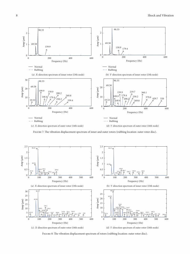
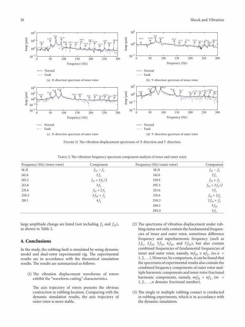

International Journal of
AerospaceEngineeringHindawi Publishing Corporationhttpwwwhindawicom Volume 2014
RoboticsJournal of
Hindawi Publishing Corporationhttpwwwhindawicom Volume 2014
Hindawi Publishing Corporationhttpwwwhindawicom Volume 2014
Active and Passive Electronic Components
Control Scienceand Engineering
Journal of
Hindawi Publishing Corporationhttpwwwhindawicom Volume 2014
International Journal of
RotatingMachinery
Hindawi Publishing Corporationhttpwwwhindawicom Volume 2014
Hindawi Publishing Corporation httpwwwhindawicom
Journal ofEngineeringVolume 2014
Submit your manuscripts athttpwwwhindawicom
VLSI Design
Hindawi Publishing Corporationhttpwwwhindawicom Volume 2014
Hindawi Publishing Corporationhttpwwwhindawicom Volume 2014
Shock and Vibration
Hindawi Publishing Corporationhttpwwwhindawicom Volume 2014
Civil EngineeringAdvances in
Acoustics and VibrationAdvances in
Hindawi Publishing Corporationhttpwwwhindawicom Volume 2014
Hindawi Publishing Corporationhttpwwwhindawicom Volume 2014
Electrical and Computer Engineering
Journal of
Advances inOptoElectronics
Hindawi Publishing Corporation httpwwwhindawicom
Volume 2014
The Scientific World JournalHindawi Publishing Corporation httpwwwhindawicom Volume 2014
SensorsJournal of
Hindawi Publishing Corporationhttpwwwhindawicom Volume 2014
Modelling amp Simulation in EngineeringHindawi Publishing Corporation httpwwwhindawicom Volume 2014
Hindawi Publishing Corporationhttpwwwhindawicom Volume 2014
Chemical EngineeringInternational Journal of Antennas and
Propagation
International Journal of
Hindawi Publishing Corporationhttpwwwhindawicom Volume 2014
Hindawi Publishing Corporationhttpwwwhindawicom Volume 2014
Navigation and Observation
International Journal of
Hindawi Publishing Corporationhttpwwwhindawicom Volume 2014
DistributedSensor Networks
International Journal of