Research Article Dielectric Behavior of Low Microwave Loss...
7
Research Article Dielectric Behavior of Low Microwave Loss Unit Cell for All Dielectric Metamaterial Tianhuan Luo, 1 Bo Li, 1 Qian Zhao, 2 and Ji Zhou 3 1 Advanced Materials Institute, Shenzhen Graduate School, Tsinghua University, Shenzhen 518055, China 2 State Key Lab of Tribology, Department of Mechanical Engineering, Tsinghua University, Beijing 100084, China 3 State Key Lab of New Ceramics and Fine Processing, Department of Materials Science and Engineering, Tsinghua University, Beijing 100084, China Correspondence should be addressed to Bo Li; [email protected] and Qian Zhao; [email protected] Received 9 December 2014; Accepted 29 January 2015 Academic Editor: Roman E. Noskov Copyright © 2015 Tianhuan Luo et al. is is an open access article distributed under the Creative Commons Attribution License, which permits unrestricted use, distribution, and reproduction in any medium, provided the original work is properly cited. With a deep study of the metamaterial, its unit cells have been widely extended from metals to dielectrics. e dielectric based unit cells attract much attention because of the advantage of easy preparation, tunability, and higher frequency response, and so forth. Using the conventional solid state method, we prepared a kind of incipient ferroelectrics (calcium titanate, CaTiO 3 ) with higher microwave permittivity and lower loss, which can be successfully used to construct metamaterials. e temperature and frequency dependence of dielectric constant are also measured under different sintering temperatures. e dielectric spectra showed a slight permittivity decrease with the increase of temperature and exhibited a loss of 0.0005, combined with a higher microwave dielectric constant of ∼167 and quality factor Q of 2049. erefore, CaTiO 3 is a kind of versatile and potential metamaterial unit cell. e permittivity of CaTiO 3 at higher microwave frequency was also examined in the rectangular waveguide and we got the permittivity of 165, creating a new method to test permittivity at higher microwave frequency. 1. Introduction Since increasing attention has been paid to metamaterials due to their novel physical behaviors and versatile applications, such as leſt-handed metamaterials (LHMs) using split ring resonators (SRRs) and metal wire arrays to produce negative effective permeability and negative permittivity, respectively [1, 2], more and more outstanding ceramic materials such as Ba Sr 1− TiO 3 (BST) are being developed and utilized to build some supernormal materials and structures, such as ferromagnetic/ferroelectric composite metamaterial (CMM) with BST rods [3], Mie resonance structures using dielectric BST particles [4, 5], the prism of negative refraction in BST columns [6], and artificial magnetic conductor with high dielectric BST arrays applied in antenna and radar [7], opening a better and more potential approach to construct various isotropic metamaterials, suitable for higher oper- ating frequencies [4]. Although BST has been successfully applied to construct metamaterials, its higher dielectric loss of 0.001 [8] limits its realization of further novel properties. erefore, a substitute of the dielectric material needs to be developed and studied. To verify its excellent dielectric properties, systemic research on CaTiO 3 was accomplished, mainly in two different ways including variation of dielectric constant against frequency in operating frequency range (10 6 Hz∼10 10 Hz) and against temperature within −65 ∘ C∼ 120 ∘ C, respectively. 2. Experimental Details To gain simplification, CaTiO 3 ceramic was synthesized through conventional solid state method. All the raw powders were mixed by ball milling with zirconia media in deionized water for 30 h. e powders were pestled in agate mortar aſter drying, sieved through 50 or 60 mesh sieve. en, PVA (polyvinyl alcohol, 5 wt%) was added to the sieved powders as organic binder to make the formation of the cylinder of 10 mm in diameter and 1–6 mm in height by uniaxial compression at 4 MPa with the customized mould. Finally Hindawi Publishing Corporation International Journal of Antennas and Propagation Volume 2015, Article ID 291234, 6 pages http://dx.doi.org/10.1155/2015/291234
Transcript of Research Article Dielectric Behavior of Low Microwave Loss...
Research ArticleDielectric Behavior of Low Microwave Loss Unit Cell forAll Dielectric Metamaterial
Tianhuan Luo,1 Bo Li,1 Qian Zhao,2 and Ji Zhou3
1Advanced Materials Institute, Shenzhen Graduate School, Tsinghua University, Shenzhen 518055, China2State Key Lab of Tribology, Department of Mechanical Engineering, Tsinghua University, Beijing 100084, China3State Key Lab of New Ceramics and Fine Processing, Department of Materials Science and Engineering, Tsinghua University,Beijing 100084, China
Correspondence should be addressed to Bo Li; [email protected] and Qian Zhao; [email protected]
Received 9 December 2014; Accepted 29 January 2015
Academic Editor: Roman E. Noskov
Copyright © 2015 Tianhuan Luo et al. This is an open access article distributed under the Creative Commons Attribution License,which permits unrestricted use, distribution, and reproduction in any medium, provided the original work is properly cited.
With a deep study of the metamaterial, its unit cells have been widely extended frommetals to dielectrics. The dielectric based unitcells attract much attention because of the advantage of easy preparation, tunability, and higher frequency response, and so forth.Using the conventional solid state method, we prepared a kind of incipient ferroelectrics (calcium titanate, CaTiO
3) with higher
microwave permittivity and lower loss, which can be successfully used to construct metamaterials. The temperature and frequencydependence of dielectric constant are also measured under different sintering temperatures. The dielectric spectra showed a slightpermittivity decrease with the increase of temperature and exhibited a loss of 0.0005, combined with a higher microwave dielectricconstant of ∼167 and quality factor Q of 2049. Therefore, CaTiO
3is a kind of versatile and potential metamaterial unit cell. The
permittivity of CaTiO3at higher microwave frequency was also examined in the rectangular waveguide and we got the permittivity
of 165, creating a new method to test permittivity at higher microwave frequency.
1. Introduction
Since increasing attention has been paid tometamaterials dueto their novel physical behaviors and versatile applications,such as left-handed metamaterials (LHMs) using split ringresonators (SRRs) and metal wire arrays to produce negativeeffective permeability and negative permittivity, respectively[1, 2], more and more outstanding ceramic materials suchas Ba𝑥Sr1−𝑥
TiO3(BST) are being developed and utilized to
build some supernormal materials and structures, such asferromagnetic/ferroelectric composite metamaterial (CMM)with BST rods [3], Mie resonance structures using dielectricBST particles [4, 5], the prism of negative refraction inBST columns [6], and artificial magnetic conductor withhigh dielectric BST arrays applied in antenna and radar [7],opening a better and more potential approach to constructvarious isotropic metamaterials, suitable for higher oper-ating frequencies [4]. Although BST has been successfullyapplied to construct metamaterials, its higher dielectric lossof 0.001 [8] limits its realization of further novel properties.
Therefore, a substitute of the dielectric material needs tobe developed and studied. To verify its excellent dielectricproperties, systemic research on CaTiO
3was accomplished,
mainly in two different ways including variation of dielectricconstant against frequency in operating frequency range(106Hz∼1010Hz) and against temperature within −65∘C∼120∘C, respectively.
2. Experimental Details
To gain simplification, CaTiO3ceramic was synthesized
through conventional solid statemethod.All the rawpowderswere mixed by ball milling with zirconia media in deionizedwater for 30 h. The powders were pestled in agate mortarafter drying, sieved through 50 or 60 mesh sieve. Then, PVA(polyvinyl alcohol, 5 wt%) was added to the sieved powdersas organic binder to make the formation of the cylinderof 10mm in diameter and 1–6mm in height by uniaxialcompression at 4MPa with the customized mould. Finally
Hindawi Publishing CorporationInternational Journal of Antennas and PropagationVolume 2015, Article ID 291234, 6 pageshttp://dx.doi.org/10.1155/2015/291234

2 International Journal of Antennas and Propagation
the cylinders were sintered at 5 or 6 kinds of temperature inthe range from 1250∘C to 1400∘C after PVA was volatilizedat 600∘C, the temperature increasing rate of which is around3∘C/min.
To catch the knowledge of density variation, Archimedesdrainage method was taken, to measure the size and weightof specimen as well. To explore the phase structure, X-raydiffraction (XRD-7000 X, SHIMADZU) analysis with Cu-K𝛼 radiation was available and accessible. The morphol-ogy and microstructure were evaluated by scanning elec-tron microscopy (SEM) with energy dispersive spectroscopy(EDS) (JSM-7001F, JEOL) on the as-sintered and fracturedsurfaces. To make the microstructure much more persuasive,the JSM-6460LV, JEOL (SEM), were also utilized to verify theprevious pictures. The dielectric properties were measuredusing the impendence analyzers Agilent HP 4192A (5Hz∼13MHz), and Agilent E4991A (1MHz∼3GHz). The 4192Ameasurements were performed at temperatures ranging from−65∘C to 120∘C and at the same time loaded with six differentfrequencies containing 10 kHz, 100 kHz, 200 kHz, 500 kHz,800 kHz, and 1MHz. The higher frequency dielectric prop-erties were tested by an Agilent HP 8720ES S-Parameternetwork analyzer (50MHz∼20GHz) using the Hakki andColeman dielectric resonator method [9] with the TE
011[10]
and TE01𝛿
[11] resonant mode of dielectric resonators excited,measuring the permittivity (including resonant frequency𝑓) and unloaded 𝑄 factor (containing 𝑄 ∗ 𝑓), respectively.Besides, to gain more understanding of higher microwavefrequency behavior, as depicted in Figure 1, we simulatedthe S-parameter of transmission (S
21) and reflection (S
11)
of the dielectric cube with Perfect Electric (PE) and Per-fect Magnetic (PM) boundary conditions along 𝑥 and 𝑦directions, respectively. And the propagation direction ofelectromagnetic wave should be along 𝑧 direction. Finally theprepared single cube CaTiO
3in 2 × 2 × 2mm was examined
in a rectangular waveguide by the network analyzer.Throughcomparing the simulation and experiment results, we cancapture the permittivity of the dielectric ceramic, which hasprovided a newmethod to examine the dielectric constant onhigher microwave frequency.
3. Results and Discussion
3.1. XRD Plots. Each dielectric ceramic sample has its ownstructure and lattice information through series of X-raydiffraction experiments of different sintering temperatures.To determine the phase of the synthesized samples, the X-ray diffraction patterns are measured and shown in Figure 2,which clearly shows orthorhombic structure for CaTiO
3in
incipient ferroelectric phase [12]. It has been proved thatCaTiO
3sintered at 1350∘C has the same lattice structure as
the unsintered ones (JCPDS number 42-0423, Pnma(62), a =5.442 A, b = 7.642 A, c = 5.381 A), while being different fromthe other ceramics sintered at 1250∘C, 1300∘C, and 1400∘C(JCPDS number 22-0153, Pnma(62), a = 5.440 A, b = 7.644 A,c = 5.381 A). The alteration of lattice parameters would beprobably related to the appearance of defects due to thedistortion in the CaTiO
3lattice [13].The red line (1350∘C) and
0 10 20
Y
Z
X
(mm)
Figure 1:The simulationmodel of dielectric ceramic cube by 2 × 2 ×2mm.
1250∘C
1300∘C
1350∘C
1400∘CIn
tens
ity (c
ount
s)
0 10 20 30 40 50 60 70 80 90 100
2𝜃 (∘)
Unsintered
(440
)(333
)(134
)
(044
)
(313
)(341
)(152
)
(161
)
(242
)
(142
)(051
)(331
)(042
)(311
)(141
)(212
)(040
)(122
)(022
)(131
)
(210
)(102
)(031
)
(12
1)
(111
)(101
)
(132)
Figure 2: XRD patterns of CaTiO3ceramics fabricated under differ-
ent sintering conditions, with respect to unsintered ones, 1250∘C,1300∘C, 1350∘C, and 1400∘C, respectively.
black line (unsintered) have the similar diffraction situation,distinguishing from the rest sintering temperatures withslopes for the small diffraction degree.
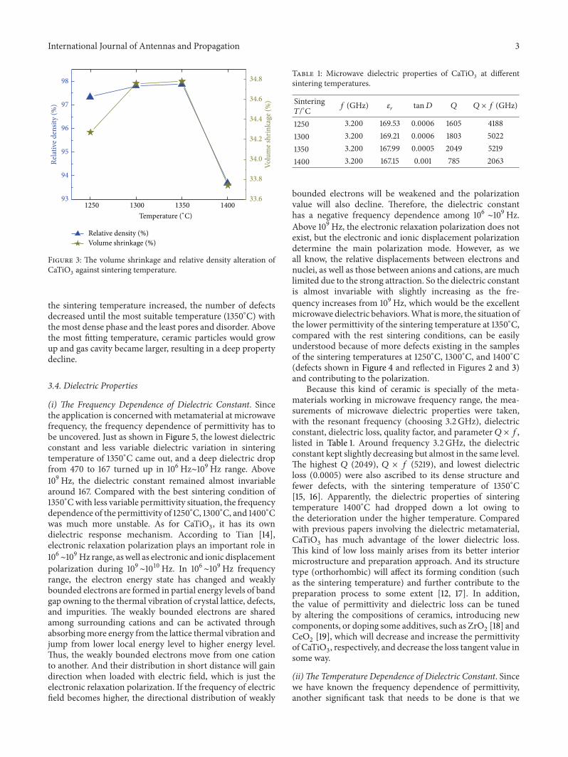
3.2. Basic Physical Properties. To make sure the preparationprocess was excellent and the macrostructure was denseenough, the volume shrinkage and relative density measure-mentwere applied to those samples of different sintering tem-peratures. Because the ceramic particles were combined withadhesive PVA, the volume anddensitywould be changed afterthe sintering process.Themost dense structure correspondedto best sintering temperature. As Figure 3 revealed, in thisexperiment, the best sintering temperature was 1350∘C, atwhich the CaTiO
3captured the largest volume shrinkage of
34.78% and the highest relative density of 97.88%.
3.3. SEM. Not only the macrostructure should be denseenough, but also the microstructure should have less defectsto win a better dielectric behavior. Figure 4 shows themicrostructures of CaTiO
3ceramics on surface and section
parts. From the surface and section, the most dense one wasallied with Figure 4(c) occupying an average particle size of3 𝜇m. More pores had the presence in the phase in Figures4(a) and 4(b), with a larger particle size in Figure 4(d). As
International Journal of Antennas and Propagation 3
1250 1300 1350 140093
94
95
96
97
98
33.6
33.8
34.0
34.2
34.4
34.6
34.8
Relat
ive d
ensit
y (%
)
Relative density (%)
Volu
me s
hrin
kage
(%)
Volume shrinkage (%)
Temperature (∘C)
Figure 3: The volume shrinkage and relative density alteration ofCaTiO
3against sintering temperature.
the sintering temperature increased, the number of defectsdecreased until the most suitable temperature (1350∘C) withthe most dense phase and the least pores and disorder. Abovethe most fitting temperature, ceramic particles would growup and gas cavity became larger, resulting in a deep propertydecline.
3.4. Dielectric Properties
(i) The Frequency Dependence of Dielectric Constant. Sincethe application is concerned with metamaterial at microwavefrequency, the frequency dependence of permittivity has tobe uncovered. Just as shown in Figure 5, the lowest dielectricconstant and less variable dielectric variation in sinteringtemperature of 1350∘C came out, and a deep dielectric dropfrom 470 to 167 turned up in 106Hz∼109Hz range. Above109Hz, the dielectric constant remained almost invariablearound 167. Compared with the best sintering condition of1350∘Cwith less variable permittivity situation, the frequencydependence of the permittivity of 1250∘C, 1300∘C, and 1400∘Cwas much more unstable. As for CaTiO
3, it has its own
dielectric response mechanism. According to Tian [14],electronic relaxation polarization plays an important role in106∼109Hz range, aswell as electronic and ionic displacementpolarization during 109∼1010Hz. In 106∼109Hz frequencyrange, the electron energy state has changed and weaklybounded electrons are formed in partial energy levels of bandgap owning to the thermal vibration of crystal lattice, defects,and impurities. The weakly bounded electrons are sharedamong surrounding cations and can be activated throughabsorbingmore energy from the lattice thermal vibration andjump from lower local energy level to higher energy level.Thus, the weakly bounded electrons move from one cationto another. And their distribution in short distance will gaindirection when loaded with electric field, which is just theelectronic relaxation polarization. If the frequency of electricfield becomes higher, the directional distribution of weakly
Table 1: Microwave dielectric properties of CaTiO3 at differentsintering temperatures.
Sintering𝑇/∘C 𝑓 (GHz) 𝜀
𝑟tan𝐷 𝑄 𝑄 × 𝑓 (GHz)
1250 3.200 169.53 0.0006 1605 41881300 3.200 169.21 0.0006 1803 50221350 3.200 167.99 0.0005 2049 52191400 3.200 167.15 0.001 785 2063
bounded electrons will be weakened and the polarizationvalue will also decline. Therefore, the dielectric constanthas a negative frequency dependence among 106 ∼109Hz.Above 109Hz, the electronic relaxation polarization does notexist, but the electronic and ionic displacement polarizationdetermine the main polarization mode. However, as weall know, the relative displacements between electrons andnuclei, as well as those between anions and cations, are muchlimited due to the strong attraction. So the dielectric constantis almost invariable with slightly increasing as the fre-quency increases from 109Hz, which would be the excellentmicrowave dielectric behaviors.What ismore, the situation ofthe lower permittivity of the sintering temperature at 1350∘C,compared with the rest sintering conditions, can be easilyunderstood because of more defects existing in the samplesof the sintering temperatures at 1250∘C, 1300∘C, and 1400∘C(defects shown in Figure 4 and reflected in Figures 2 and 3)and contributing to the polarization.
Because this kind of ceramic is specially of the meta-materials working in microwave frequency range, the mea-surements of microwave dielectric properties were taken,with the resonant frequency (choosing 3.2 GHz), dielectricconstant, dielectric loss, quality factor, and parameter 𝑄 × 𝑓,listed in Table 1. Around frequency 3.2GHz, the dielectricconstant kept slightly decreasing but almost in the same level.The highest 𝑄 (2049), 𝑄 × 𝑓 (5219), and lowest dielectricloss (0.0005) were also ascribed to its dense structure andfewer defects, with the sintering temperature of 1350∘C[15, 16]. Apparently, the dielectric properties of sinteringtemperature 1400∘C had dropped down a lot owing tothe deterioration under the higher temperature. Comparedwith previous papers involving the dielectric metamaterial,CaTiO
3has much advantage of the lower dielectric loss.
This kind of low loss mainly arises from its better interiormicrostructure and preparation approach. And its structuretype (orthorhombic) will affect its forming condition (suchas the sintering temperature) and further contribute to thepreparation process to some extent [12, 17]. In addition,the value of permittivity and dielectric loss can be tunedby altering the compositions of ceramics, introducing newcomponents, or doping some additives, such as ZrO
2[18] and
CeO2[19], which will decrease and increase the permittivity
of CaTiO3, respectively, and decrease the loss tangent value in
some way.
(ii) The Temperature Dependence of Dielectric Constant. Sincewe have known the frequency dependence of permittivity,another significant task that needs to be done is that we

4 International Journal of Antennas and Propagation
Surface
Section
10𝜇m
5𝜇m
(a)
Surface
Section
10𝜇m
5𝜇m
(b)
Surface
Section
10𝜇m
5𝜇m
(c)
Surface
Section
10𝜇m
5𝜇m
(d)
Figure 4: Images of Scanning Electron Microscope at different sintering temperatures for CaTiO3at (a) 1250∘C, (b) 1300∘C, (c) 1350∘C, and
(d) 1400∘C by surface and section.
106 107 108 109 1010
200
300
400
500
600
700
lg d
iele
ctric
cons
tant
lg frequency (Hz)
1250∘C1300∘C
1350∘C1400∘C
Figure 5: Dielectric constant variation against frequency at 25∘C forCaTiO
3sintered at 1250∘C, 1300∘C, 1350∘C, and 1400∘C, respectively.
should study the temperature dependence of permittivityto reveal the variation of dielectric constant. The similarsituations for each sintering temperature are displayed inFigure 6, where the decreasing dielectric constant existedwhen the temperature increased. This should be interpretedby the theory of Bosman and Havinga [20, 21], improvedby Bartels and Smith [22], saying that the temperaturedependence of permittivity is negative when 𝜀
𝑟> 20. Fur-
thermore, the sintering temperature of 1350∘C made CaTiO3
occupy a slight dielectric constant descending around 475.The phenomenon of possessing larger dielectric constant inthe sintering temperatures of 1250∘C, 1300∘C, and 1400∘C
0 30 60 90 120 150450
500
550
600
650
700
Die
lect
ric co
nsta
nt
−90 −60 −30
1300∘C1350∘C1400∘C
1250∘C
Temperature (∘C)
Figure 6: Dielectric constant variation against temperature at500 kHz for CaTiO
3, sintered at 1250∘C, 1300∘C, 1350∘C, and 1400∘C,
respectively.
would also be attributed to the defects, contributing effectiveelectric charge, adding the polarization possibility, and finallyresulting in improved permittivity.
3.5. Permittivity Tested at Higher Microwave Frequency. Toget further comprehension of the higher frequency resonanceof CaTiO
3, a method was utilized to examine and retrieve
the permittivity, based on the fact that the limited measuringtechnology and fewer methods could test the dielectricconstant around or above 1010Hz. The new method is to put

International Journal of Antennas and Propagation 5
8 9 10 11 12 13
0
10
Experiments Simulations
Frequency (GHz)
−80
−70
−60
−50
−40
−30
−20
−10
Refle
ctio
n an
d tr
ansm
issio
n (d
B)
S11S21
S11S21
Figure 7: CaTiO3cube by 2 × 2 × 2mm was tested in waveguide
with the magnitude of S parameter: S21of transmission and S
11of
reflection, including the comparison of simulations and experimentson S11and S
21.
the single cube of 2 × 2 × 2mm specimen into a rectangu-lar waveguide and measure the microwave S-Parameter oftransmission (S
21) and reflection (S
11) and phase of S
21by
an HP8720ES network analyzer. As mentioned in [4], thefirst resonance frequency is completely determined by dielec-tric constant. We can get the permittivity of the dielectricceramics through comparing the computer simulation usingthe finite-difference time domain solver and experimentalresults from the testing in the rectangular waveguide. Asdemonstrated in Figure 7, the experiments and simulations ofthe S-Parameter have a great correspondence and consistencyin the range from 8GHz to 13GHz. Around 9.8GHz, −3.3 dBfor S11
simulated and −3.6 dB for S11
in experiment wereobserved, as well as −11 dB for S
21simulated and −5.6 dB
for S21
in experiment. Finally, we have got the permittivityof CaTiO
3for around 165, which is extremely close to the
microwave testing result.
4. Conclusion
Through systemic experiments, CaTiO3was fabricated by
solid state method under better suitable sintering tempera-ture of 1350∘C with a volume shrinkage of 34.78%, relativedensity of 97.88%, which is better than the value of 95%[12]. The X-ray diffraction and SEM had shown a perovskiteorthorhombic structure and a dense crystal microstructure.The dielectric spectra revealed a deep dielectric drop from470 to 167 in the range 106Hz∼109Hz and exhibited alower microwave loss of 0.0005, combined with a highermicrowave dielectric constant of ∼167 andmicrowave qualityfactor 𝑄 of 2049 and 𝑄 × 𝑓 of 5219GHz, respectively. Alsoslight decrease versus temperature for the permittivity wasinvestigated systemically. The single cube CaTiO
3with a size
of 2 × 2 × 2mm was examined in a rectangular waveguidefrom 8GHz to 13GHz, with a resonant frequency of 9.8GHz,which agrees with the simulation. We got the permittivityof 165 for CaTiO
3at higher microwave frequency, very close
to the microwave result of ∼167. Therefore, CaTiO3is a kind
of versatile and potential metamaterial unit cell and a newdielectric examination method is created.
Conflict of Interests
The authors declare that there is no conflict of interestsregarding the publication of this paper.
Acknowledgments
This work is supported by the National High TechnologyResearch and Development Program of China (Grant no.2012AA030403), the National Natural Science Foundationof China (Grant nos. 61275176 and 51032003), and theScience and Technology Plan of Shenzhen City of China(Grant nos. JCYJ20120619152711509 and JC201105180802A).Acknowledgment also goes to Professor Fuli Zhang for hishelpful guidance and corrections of the paper. The apprecia-tion of assisting in experiments is attributed to Hongya Wu,Xiaoming Liu, and Chuwen Lan, and so forth.
References
[1] J. B. Pendry, A. J. Holden, W. J. Stewart, and I. Youngs,“Extremely low frequency plasmons in metallic mesostruc-tures,” Physical Review Letters, vol. 76, no. 25, pp. 4773–4776,1996.
[2] J. B. Pendry, A. J. Holden, D. J. Robbins, andW. J. Stewart, “Mag-netism from conductors and enhanced nonlinear phenomena,”IEEE Transactions onMicrowaveTheory and Techniques, vol. 47,no. 11, pp. 2075–2084, 1999.
[3] H. J. Zhao, L. Kang, J. Zhou et al., “Experimental demonstrationof tunable negative phase velocity and negative refraction ina ferromagnetic/ferroelectric composite metamaterial,” AppliedPhysics Letters, vol. 93, no. 20, Article ID 201106, 2008.
[4] Q. Zhao, J. Zhou, F. L. Zhang, and D. Lippens, “Mie resonance-based dielectric metamaterials,”Materials Today, vol. 12, no. 12,pp. 60–69, 2009.
[5] Q. Zhao, L. Kang, B. Du et al., “Experimental demonstration ofisotropic negative permeability in a three-dimensional dielec-tric composite,” Physical Review Letters, vol. 101, no. 2, ArticleID 027402, 2008.
[6] Y. Z. Sun, Y. F. Sun, L. X. Ran, W. G. Wang, L. Peng, and Q. L.Chen, “Experimental verification onnegative refraction of BST,”Scientia Sinica Physica, Mechanica & Astronomica, vol. 40, no.12, pp. 1476–1481, 2010.
[7] F. L. Zhang, D. Lippens, and A. L. Borja, “Low profile smallantenna using ferroelectrics cube based artificial magneticconductor,” in Proceedings of the 4th European Conference onAntennas and Propagation (EuCAP ’10), April 2010.
[8] L. C. Sengupta and S. Sengupta, “Breakthrough advancesin low loss, tunable dielectric materials,” Materials ResearchInnovations, vol. 2, no. 5, pp. 278–282, 1999.
[9] B. W. Hakki and P. D. Coleman, “A dielectric resonator methodof measuring inductive capacities in the millimeter range,” RE

6 International Journal of Antennas and Propagation
Transactions on MicrowaveTheory and Techniques, vol. 8, no. 4,pp. 402–410, 1960.
[10] W. E. Courtney, “Analysis and evaluation of a method of mea-suring the complex permittivity and permeability microwaveinsulators,” IEEE Transactions on Microwave Theory and Tech-niques, vol. 18, no. 8, pp. 476–485, 1970.
[11] J. Krupka, K. Derzakowski, B. Riddle, and J. B. Jarvis, “Adielectric resonator for measurements of complex permittivityof low loss dielectric materials as a function of temperature,”Measurement Science and Technology, vol. 9, no. 10, pp. 1751–1756, 1998.
[12] V. V. Lemanov, A. V. Sotnikov, E. P. Smirnova, M. Weihnacht,and R. Kunze, “Perovskite CaTiO
3as an incipient ferroelectric,”
Solid State Communications, vol. 110, no. 11, pp. 611–614, 1999.[13] L. S. Cavalcante, V. S.Marques, J. C. Sczancoski et al., “Synthesis,
structural refinement and optical behavior of CaTiO3powders:
a comparative study of processing in different furnaces,” Chem-ical Engineering Journal, vol. 143, no. 1–3, pp. 299–307, 2008.
[14] S. Tian, Physical Properties of Materials, Beihang UniversityPress, Beijing, China, 2001.
[15] A. Pashkin, S. Kamba,M. Berta et al., “High frequency dielectricproperties of CaTiO
3-based microwave ceramics,” Journal of
Physics D: Applied Physics, vol. 38, no. 5, pp. 741–748, 2005.[16] H. F. Kay and P. C. Bailey, “Structure and properties of CaTiO
3,”
Acta Crystallographica, vol. 10, no. 3, pp. 219–226, 1957.[17] H. K. Zhu, M. Liu, and H. Q. Zhou, “Effects of additives on
CaTiO3properties,” Electronic Components &Materials, vol. 24,
no. 7, 2005.[18] H. Y. Wu, J. Zhou, C. W. Lan, Y. S. Guo, and K. Bi, “Microwave
memristive-like nonlinearity in a dielectric metamaterial,” Sci-entific Reports, vol. 4, p. 5499, 2014.
[19] E. R. Kipkoech, F. Azough, and R. Freer, “The effect of CeO2on
the microstructure and dielectric properties of CaTiO3-based
ceramics,” European Ceramic Society, vol. 206, no. 2, pp. 2213–2216, 2002.
[20] E. E. Havinga, “The temperature dependence of dielectric con-stants,” Journal of Physics and Chemistry of Solids, vol. 18, no.2-3, pp. 253–255, 1961.
[21] A. J. Bosman and E. E. Havinga, “Temperature dependence ofdielectric constants of cubic ionic compounds,” Physical Review,vol. 129, no. 4, pp. 1593–1600, 1963.
[22] R. A. Bartels and P. A. Smith, “Pressure and temperaturedependence of the static dielectric constants of KCl, NaCl, LiF,and MgO,” Physical Review B, vol. 7, no. 8, pp. 3885–3892, 1973.

International Journal of
AerospaceEngineeringHindawi Publishing Corporationhttp://www.hindawi.com Volume 2014
RoboticsJournal of
Hindawi Publishing Corporationhttp://www.hindawi.com Volume 2014
Hindawi Publishing Corporationhttp://www.hindawi.com Volume 2014
Active and Passive Electronic Components
Control Scienceand Engineering
Journal of
Hindawi Publishing Corporationhttp://www.hindawi.com Volume 2014
International Journal of
RotatingMachinery
Hindawi Publishing Corporationhttp://www.hindawi.com Volume 2014
Hindawi Publishing Corporation http://www.hindawi.com
Journal ofEngineeringVolume 2014
Submit your manuscripts athttp://www.hindawi.com
VLSI Design
Hindawi Publishing Corporationhttp://www.hindawi.com Volume 2014
Hindawi Publishing Corporationhttp://www.hindawi.com Volume 2014
Shock and Vibration
Hindawi Publishing Corporationhttp://www.hindawi.com Volume 2014
Civil EngineeringAdvances in
Acoustics and VibrationAdvances in
Hindawi Publishing Corporationhttp://www.hindawi.com Volume 2014
Hindawi Publishing Corporationhttp://www.hindawi.com Volume 2014
Electrical and Computer Engineering
Journal of
Advances inOptoElectronics
Hindawi Publishing Corporation http://www.hindawi.com
Volume 2014
The Scientific World JournalHindawi Publishing Corporation http://www.hindawi.com Volume 2014
SensorsJournal of
Hindawi Publishing Corporationhttp://www.hindawi.com Volume 2014
Modelling & Simulation in EngineeringHindawi Publishing Corporation http://www.hindawi.com Volume 2014
Hindawi Publishing Corporationhttp://www.hindawi.com Volume 2014
Chemical EngineeringInternational Journal of Antennas and
Propagation
International Journal of
Hindawi Publishing Corporationhttp://www.hindawi.com Volume 2014
Hindawi Publishing Corporationhttp://www.hindawi.com Volume 2014
Navigation and Observation
International Journal of
Hindawi Publishing Corporationhttp://www.hindawi.com Volume 2014
DistributedSensor Networks
International Journal of


![Dielectric characterization of microwave sintered lead ...cdmf.org.br/wp-content/uploads/2016/11/Goncalves-2016-Dielectric... · ceramics by microwave radiation [12]. Since the first](https://static.fdocuments.us/doc/165x107/5fc1c8c131fd0b11cc286f9d/dielectric-characterization-of-microwave-sintered-lead-cdmforgbrwp-contentuploads201611goncalves-2016-dielectric.jpg)