RESEARCH ARTICLE Dexin MA Novel casting processes for … · investment casting process remains the...
14
RESEARCH ARTICLE Dexin MA Novel casting processes for single-crystal turbine blades of superalloys © The Author(s) 2018. This article is published with open access at link.springer.com and journal.hep.com.cn Abstract This paper presents a brief review of the current casting techniques for single-crystal (SC) blades, as well as an analysis of the solidification process in complex turbine blades. A series of novel casting methods based on the Bridgman process were presented to illustrate the development in the production of SC blades from super- alloys. The grain continuator and the heat conductor techniques were developed to remove geometry-related grain defects. In these techniques, the heat barrier that hinders lateral SC growth from the blade airfoil into the extremities of the platform is minimized. The parallel heating and cooling system was developed to achieve symmetric thermal conditions for SC solidification in blade clusters, thus considerably decreasing the negative shadow effect and its related defects in the current Bridgman process. The dipping and heaving technique, in which thin- shell molds are utilized, was developed to enable the establishment of a high temperature gradient for SC growth and the freckle-free solidification of superalloy castings. Moreover, by applying the targeted cooling and heating technique, a novel concept for the three-dimen- sional and precise control of SC growth, a proper thermal arrangement may be dynamically established for the microscopic control of SC growth in the critical areas of large industrial gas turbine blades. Keywords superalloy, investment casting, Bridgman process, directional solidification, single crystal, turbine blade 1 Introduction Turbine blades fabricated from Ni-based superalloys are widely used in aero-engines and industrial gas turbines (IGT). From a material property perspective, the limiting component of a gas turbine is the first-stage blade, which is under the highest gas-temperature stresses (Fig. 1). Ni- based superalloys are the preferred material for turbine blades given their high temperature strength, microstruc- tural stability, and corrosion resistance. Improvements in casting methods and the chemical composition of alloys used for the production of rotor blades have directly increased rotor inlet temperature, subsequently increasing efficiency. Casting methods have been improved from conventional investment casting, which produces an equiaxed (EQ)-grain structure, to directional solidification (DS), which produces columnar-grain (CG) and single- crystal (SC) structures. Although polycrystalline Ni-based superalloys are inherently strong, their properties can be further improved through processing. In the case of rotor blades where the primary stress axis is along the length of the blade, aligning grains along the stress direction can improve creep rupture life, creep rupture ductility, and thermal fatigue resistance [1–3]. DS is used to produce oriented CG or SC structures to align or completely eliminate grain boundaries. Developments in chemical composition and advanced processing have enabled the fabrication of Ni-based superalloys with capabilities far beyond that imagined at the beginning of superalloy development. Advancements in alloy composition have resulted from modifying different casting techniques, as well as generational developments, and have subsequently improved the high-temperature capabilities of alloys. SC superalloys are currently used in increasing quantities in gas turbine engines (Fig. 1), although the use of castings in the columnar and EQ forms remains practical in many instances. Turbine blades are typically produced in an investment casting process, which has also been called lost wax and precision casting. This method is especially suitable for casting components with complex and near-net shape geometry. Casting begins with the preparation of the wax pattern of the final component by injecting molten wax into Received April 4, 2017; accepted July 3, 2017 Dexin MA (✉) Wedge Central South Research Institute, Shenzhen 518045, China E-mail: [email protected] Front. Mech. Eng. 2018, 13(1): 3–16 https://doi.org/10.1007/s11465-018-0475-0
Transcript of RESEARCH ARTICLE Dexin MA Novel casting processes for … · investment casting process remains the...
RESEARCH ARTICLE
Dexin MA
Novel casting processes for single-crystal turbine blades ofsuperalloys
© The Author(s) 2018. This article is published with open access at link.springer.com and journal.hep.com.cn
Abstract This paper presents a brief review of thecurrent casting techniques for single-crystal (SC) blades, aswell as an analysis of the solidification process in complexturbine blades. A series of novel casting methods based onthe Bridgman process were presented to illustrate thedevelopment in the production of SC blades from super-alloys. The grain continuator and the heat conductortechniques were developed to remove geometry-relatedgrain defects. In these techniques, the heat barrier thathinders lateral SC growth from the blade airfoil into theextremities of the platform is minimized. The parallelheating and cooling system was developed to achievesymmetric thermal conditions for SC solidification in bladeclusters, thus considerably decreasing the negative shadoweffect and its related defects in the current Bridgmanprocess. The dipping and heaving technique, in which thin-shell molds are utilized, was developed to enable theestablishment of a high temperature gradient for SCgrowth and the freckle-free solidification of superalloycastings. Moreover, by applying the targeted cooling andheating technique, a novel concept for the three-dimen-sional and precise control of SC growth, a proper thermalarrangement may be dynamically established for themicroscopic control of SC growth in the critical areas oflarge industrial gas turbine blades.
Keywords superalloy, investment casting, Bridgmanprocess, directional solidification, single crystal, turbineblade
1 Introduction
Turbine blades fabricated from Ni-based superalloys are
widely used in aero-engines and industrial gas turbines(IGT). From a material property perspective, the limitingcomponent of a gas turbine is the first-stage blade, which isunder the highest gas-temperature stresses (Fig. 1). Ni-based superalloys are the preferred material for turbineblades given their high temperature strength, microstruc-tural stability, and corrosion resistance. Improvements incasting methods and the chemical composition of alloysused for the production of rotor blades have directlyincreased rotor inlet temperature, subsequently increasingefficiency. Casting methods have been improved fromconventional investment casting, which produces anequiaxed (EQ)-grain structure, to directional solidification(DS), which produces columnar-grain (CG) and single-crystal (SC) structures. Although polycrystalline Ni-basedsuperalloys are inherently strong, their properties can befurther improved through processing. In the case of rotorblades where the primary stress axis is along the length ofthe blade, aligning grains along the stress direction canimprove creep rupture life, creep rupture ductility, andthermal fatigue resistance [1–3]. DS is used to produceoriented CG or SC structures to align or completelyeliminate grain boundaries. Developments in chemicalcomposition and advanced processing have enabled thefabrication of Ni-based superalloys with capabilities farbeyond that imagined at the beginning of superalloydevelopment. Advancements in alloy composition haveresulted from modifying different casting techniques, aswell as generational developments, and have subsequentlyimproved the high-temperature capabilities of alloys. SCsuperalloys are currently used in increasing quantities ingas turbine engines (Fig. 1), although the use of castings inthe columnar and EQ forms remains practical in manyinstances.Turbine blades are typically produced in an investment
casting process, which has also been called lost wax andprecision casting. This method is especially suitable forcasting components with complex and near-net shapegeometry. Casting begins with the preparation of the waxpattern of the final component by injecting molten wax into
Received April 4, 2017; accepted July 3, 2017
Dexin MA (✉)Wedge Central South Research Institute, Shenzhen 518045, ChinaE-mail: [email protected]
Front. Mech. Eng. 2018, 13(1): 3–16https://doi.org/10.1007/s11465-018-0475-0

a metallic die with a ceramic core, which is a replica of therequired cooling passages in hollow blades. To produce SCblades, the wax patterns should be welded with grainselectors at their bottom. Large blade patterns for IGT aregenerally set up and processed individually. By contrast,small- and medium-sized patterns, such as those for theproduction of aero-engines, are usually assembled intocluster configurations, as shown in Fig. 2(a). Thisconfiguration produces several blades in a single castingcluster. The wax assembly is then repeatedly coated bydipping into ceramic slurries, followed by stuccoing withceramic sands to build a ceramic shell mold around thewax pattern. The shell mold is de-waxed in a steamautoclave after the desired shell-wall thickness is attained(Fig. 2(b)). Prior to casting, the shell is fired in a heatingfurnace to develop the strength required to contain themolten metal.Over the past years, rapid prototyping (RP) systems
have been increasingly applied in wax-pattern manufactur-ing to reduce production time and costs [4–7]. However,owing to the “step effect” generated with the layer stackingand the surface roughness of the fabricated parts, RPtechnology remains limited to the production of singlecasting or small production units. The conventionalinvestment casting process remains the only availableoption for the mass production of gas turbine blades withexcellent surface finish. This process, however, suffersfrom long lead time and high tooling costs.The SC blades of superalloys are currently produced
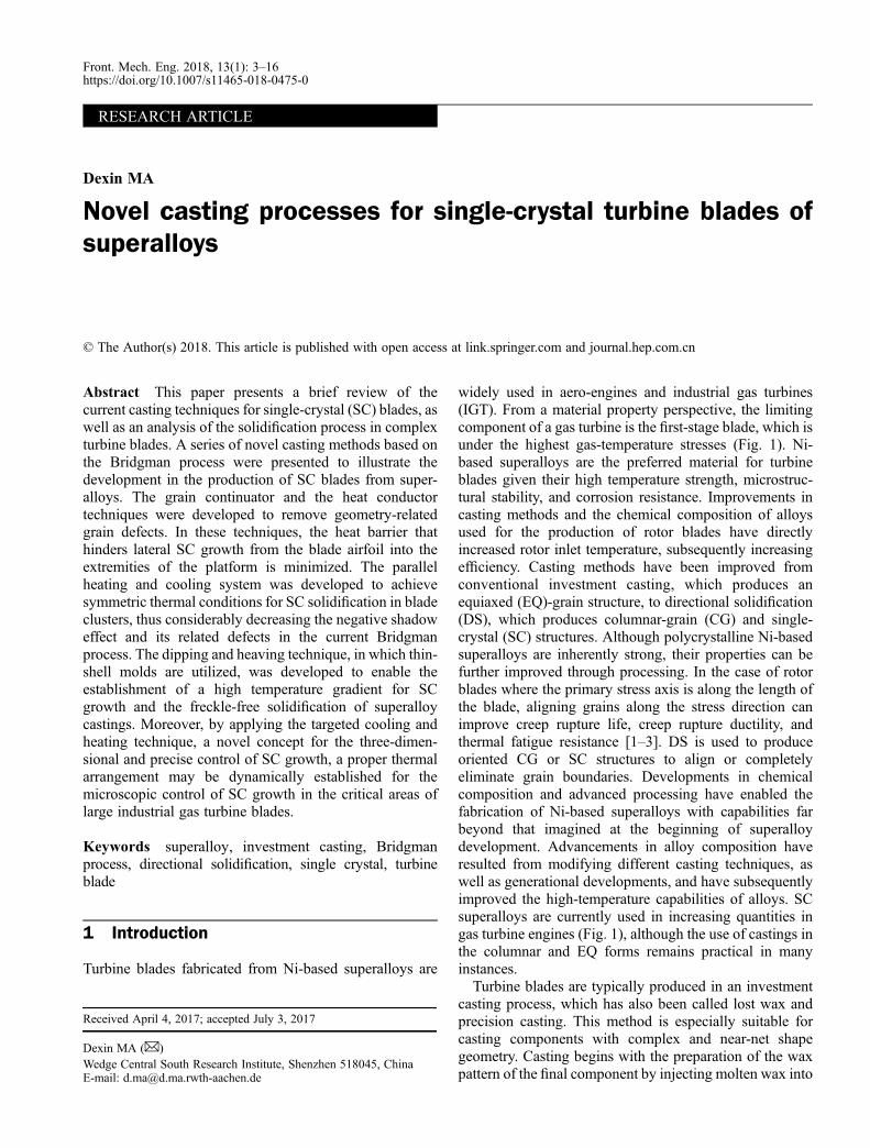
through the well-known Bridgman process [8–10]. Apositive thermal gradient (G) sufficient for DS can beachieved by utilizing the concept of mold translation and aradiation baffle. A high G at the solidification front ensuressequential solidification along the axial direction andprevents EQ grains from initiating in constitutionalundercooling zones within the melt. In addition, a finemicrostructure with small dendrite spacing can be obtainedwith a high G, thus decreasing the time and cost of the heattreatment required to homogenize the highly alloyedmaterials. Therefore, processing technologies that allowfor a high G in DS/SC process are necessary.As shown in Fig. 3(a), the Bridgman furnace consists of
an upper mold-heating chamber and a lower withdrawalchamber. These two chambers are separated by a radiationbaffle. When a suitable vacuum is achieved, the mold israised into the heating chamber, which is maintained at atemperature above the liquidus by a graphite heater. Afterpouring, the shell mold that contains the alloy melt iswithdrawn at a programmed rate from the heating zonethrough the baffle into the cooling zone of the furnace. Thewithdrawal rate is typically set at a few millimeters perminute to allow the solid/liquid interface to progressgradually along the casting. This method has been
Fig. 1 (a) High-pressure turbine rotor assembled with (b) SC blades
Fig. 2 (a) Circular-clustered wax assembly; (b) the correspond-ing shell mold manufactured for casting SC blades
4 Front. Mech. Eng. 2018, 13(1): 3–16
originally employed in the DS process to produce CGs,which are elongated in the direction of withdrawal suchthat transverse grain boundaries are absent. In a variant ofthis process, the grain boundaries are removed entirely.Grain boundaries are typically removed by adding a grainselector between the blade bottom and the starter top [9].The grain selector is usually in the form of a pig-tail-shaped spiral (Fig. 3(b)). Given that the selector is notsignificantly larger in cross-section than the grain size,only a single grain enters the cavity of the casting, whichthen exists in monocrystalline form. Alternatively, a seedcan be introduced to the base of the casting, provided theprocessing conditions are selected such that the seed is notentirely remelted and growth occurs with an orientationconsistent with that of the seed. Thus, a directionalsolidified SC structure will then be formed from the bottomto the top of the blades.Modified Bridgman techniques, such as the liquid metal
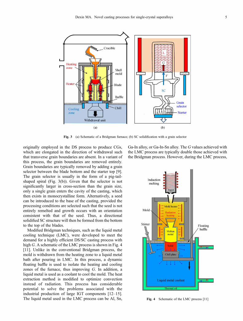
cooling technique (LMC), were developed to meet thedemand for a highly efficient DS/SC casting process withhighG. A schematic of the LMC process is shown in Fig. 4[11]. Unlike in the conventional Bridgman process, themold is withdrawn from the heating zone to a liquid metalbath after pouring in LMC. In this process, a dynamicfloating baffle is used to isolate the heating and coolingzones of the furnace, thus improving G. In addition, aliquid metal is used as a coolant to cool the mold. The heatextraction method is modified to optimize convectioninstead of radiation. This process has considerablepotential to solve the problems associated with theindustrial production of large IGT components [12–15].The liquid metal used in the LMC process can be Al, Sn,
Ga-In alloy, or Ga-In-Sn alloy. The G values achieved withthe LMC process are typically double those achieved withthe Bridgman process. However, during the LMC process,
Fig. 3 (a) Schematic of a Bridgman furnace; (b) SC solidification with a grain selector
Fig. 4 Schematic of the LMC process [11]
Dexin MA. Novel casting processes for single-crystal superalloys 5
the ceramic mold may crack because it suffers fromconsiderable thermal impact when immersed in the liquidbath. Mold cracking allows the liquid metal to come incontact with superalloy components. In this case, thecasting will be contaminated, and its performance will bedegraded [16,17].Although higher cooling rates and finer microstructures
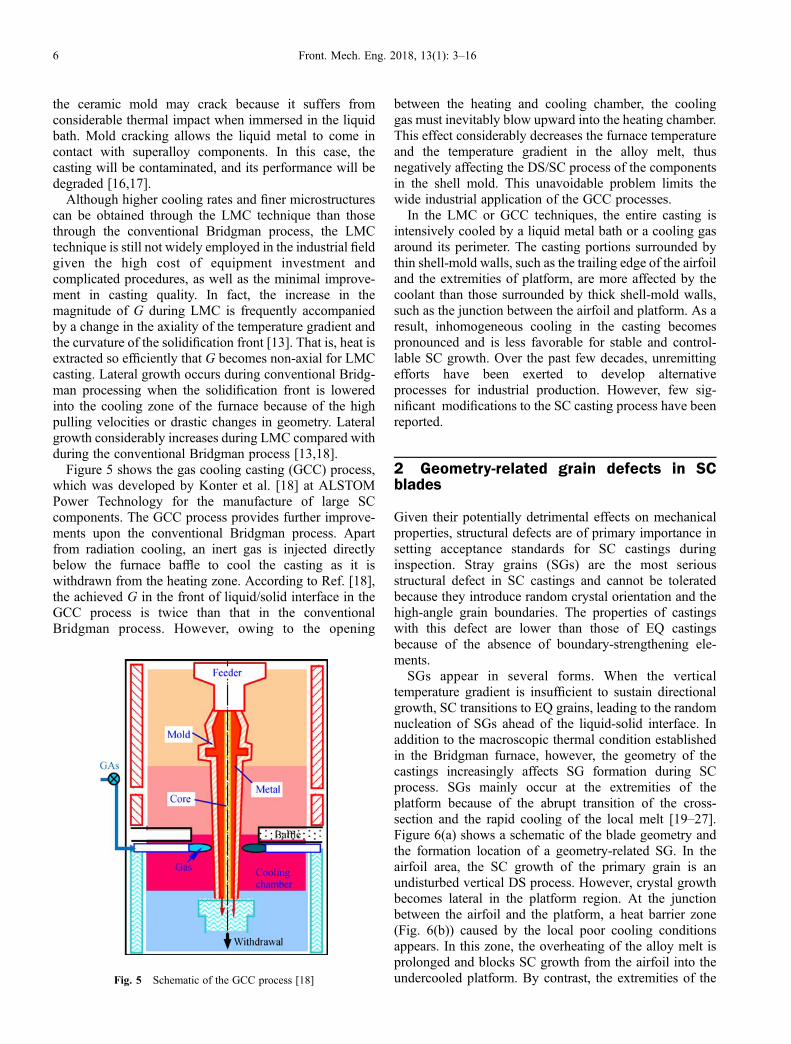
can be obtained through the LMC technique than thosethrough the conventional Bridgman process, the LMCtechnique is still not widely employed in the industrial fieldgiven the high cost of equipment investment andcomplicated procedures, as well as the minimal improve-ment in casting quality. In fact, the increase in themagnitude of G during LMC is frequently accompaniedby a change in the axiality of the temperature gradient andthe curvature of the solidification front [13]. That is, heat isextracted so efficiently that G becomes non-axial for LMCcasting. Lateral growth occurs during conventional Bridg-man processing when the solidification front is loweredinto the cooling zone of the furnace because of the highpulling velocities or drastic changes in geometry. Lateralgrowth considerably increases during LMC compared withduring the conventional Bridgman process [13,18].Figure 5 shows the gas cooling casting (GCC) process,
which was developed by Konter et al. [18] at ALSTOMPower Technology for the manufacture of large SCcomponents. The GCC process provides further improve-ments upon the conventional Bridgman process. Apartfrom radiation cooling, an inert gas is injected directlybelow the furnace baffle to cool the casting as it iswithdrawn from the heating zone. According to Ref. [18],the achieved G in the front of liquid/solid interface in theGCC process is twice than that in the conventionalBridgman process. However, owing to the opening
between the heating and cooling chamber, the coolinggas must inevitably blow upward into the heating chamber.This effect considerably decreases the furnace temperatureand the temperature gradient in the alloy melt, thusnegatively affecting the DS/SC process of the componentsin the shell mold. This unavoidable problem limits thewide industrial application of the GCC processes.In the LMC or GCC techniques, the entire casting is
intensively cooled by a liquid metal bath or a cooling gasaround its perimeter. The casting portions surrounded bythin shell-mold walls, such as the trailing edge of the airfoiland the extremities of platform, are more affected by thecoolant than those surrounded by thick shell-mold walls,such as the junction between the airfoil and platform. As aresult, inhomogeneous cooling in the casting becomespronounced and is less favorable for stable and control-lable SC growth. Over the past few decades, unremittingefforts have been exerted to develop alternativeprocesses for industrial production. However, few sig-nificant modifications to the SC casting process have beenreported.
2 Geometry-related grain defects in SCblades
Given their potentially detrimental effects on mechanicalproperties, structural defects are of primary importance insetting acceptance standards for SC castings duringinspection. Stray grains (SGs) are the most seriousstructural defect in SC castings and cannot be toleratedbecause they introduce random crystal orientation and thehigh-angle grain boundaries. The properties of castingswith this defect are lower than those of EQ castingsbecause of the absence of boundary-strengthening ele-ments.SGs appear in several forms. When the vertical
temperature gradient is insufficient to sustain directionalgrowth, SC transitions to EQ grains, leading to the randomnucleation of SGs ahead of the liquid-solid interface. Inaddition to the macroscopic thermal condition establishedin the Bridgman furnace, however, the geometry of thecastings increasingly affects SG formation during SCprocess. SGs mainly occur at the extremities of theplatform because of the abrupt transition of the cross-section and the rapid cooling of the local melt [19–27].Figure 6(a) shows a schematic of the blade geometry andthe formation location of a geometry-related SG. In theairfoil area, the SC growth of the primary grain is anundisturbed vertical DS process. However, crystal growthbecomes lateral in the platform region. At the junctionbetween the airfoil and the platform, a heat barrier zone(Fig. 6(b)) caused by the local poor cooling conditionsappears. In this zone, the overheating of the alloy melt isprolonged and blocks SC growth from the airfoil into theundercooled platform. By contrast, the extremities of theFig. 5 Schematic of the GCC process [18]
6 Front. Mech. Eng. 2018, 13(1): 3–16
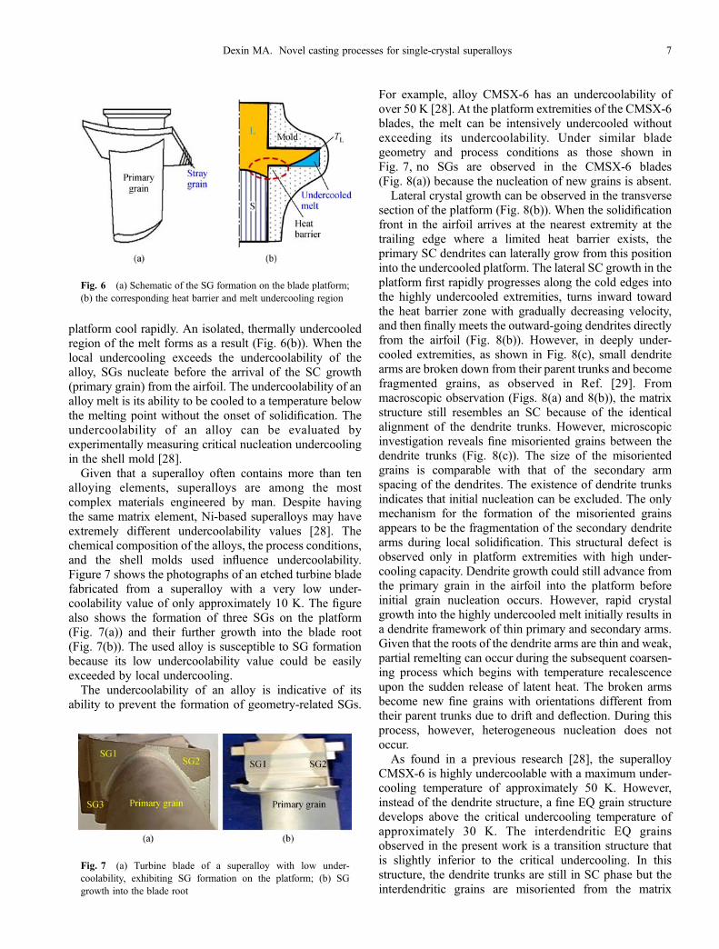
platform cool rapidly. An isolated, thermally undercooledregion of the melt forms as a result (Fig. 6(b)). When thelocal undercooling exceeds the undercoolability of thealloy, SGs nucleate before the arrival of the SC growth(primary grain) from the airfoil. The undercoolability of analloy melt is its ability to be cooled to a temperature belowthe melting point without the onset of solidification. Theundercoolability of an alloy can be evaluated byexperimentally measuring critical nucleation undercoolingin the shell mold [28].Given that a superalloy often contains more than ten
alloying elements, superalloys are among the mostcomplex materials engineered by man. Despite havingthe same matrix element, Ni-based superalloys may haveextremely different undercoolability values [28]. Thechemical composition of the alloys, the process conditions,and the shell molds used influence undercoolability.Figure 7 shows the photographs of an etched turbine bladefabricated from a superalloy with a very low under-coolability value of only approximately 10 K. The figurealso shows the formation of three SGs on the platform(Fig. 7(a)) and their further growth into the blade root(Fig. 7(b)). The used alloy is susceptible to SG formationbecause its low undercoolability value could be easilyexceeded by local undercooling.The undercoolability of an alloy is indicative of its
ability to prevent the formation of geometry-related SGs.
For example, alloy CMSX-6 has an undercoolability ofover 50 K [28]. At the platform extremities of the CMSX-6blades, the melt can be intensively undercooled withoutexceeding its undercoolability. Under similar bladegeometry and process conditions as those shown inFig. 7, no SGs are observed in the CMSX-6 blades(Fig. 8(a)) because the nucleation of new grains is absent.Lateral crystal growth can be observed in the transverse
section of the platform (Fig. 8(b)). When the solidificationfront in the airfoil arrives at the nearest extremity at thetrailing edge where a limited heat barrier exists, theprimary SC dendrites can laterally grow from this positioninto the undercooled platform. The lateral SC growth in theplatform first rapidly progresses along the cold edges intothe highly undercooled extremities, turns inward towardthe heat barrier zone with gradually decreasing velocity,and then finally meets the outward-going dendrites directlyfrom the airfoil (Fig. 8(b)). However, in deeply under-cooled extremities, as shown in Fig. 8(c), small dendritearms are broken down from their parent trunks and becomefragmented grains, as observed in Ref. [29]. Frommacroscopic observation (Figs. 8(a) and 8(b)), the matrixstructure still resembles an SC because of the identicalalignment of the dendrite trunks. However, microscopicinvestigation reveals fine misoriented grains between thedendrite trunks (Fig. 8(c)). The size of the misorientedgrains is comparable with that of the secondary armspacing of the dendrites. The existence of dendrite trunksindicates that initial nucleation can be excluded. The onlymechanism for the formation of the misoriented grainsappears to be the fragmentation of the secondary dendritearms during local solidification. This structural defect isobserved only in platform extremities with high under-cooling capacity. Dendrite growth could still advance fromthe primary grain in the airfoil into the platform beforeinitial grain nucleation occurs. However, rapid crystalgrowth into the highly undercooled melt initially results ina dendrite framework of thin primary and secondary arms.Given that the roots of the dendrite arms are thin and weak,partial remelting can occur during the subsequent coarsen-ing process which begins with temperature recalescenceupon the sudden release of latent heat. The broken armsbecome new fine grains with orientations different fromtheir parent trunks due to drift and deflection. During thisprocess, however, heterogeneous nucleation does notoccur.As found in a previous research [28], the superalloy
CMSX-6 is highly undercoolable with a maximum under-cooling temperature of approximately 50 K. However,instead of the dendrite structure, a fine EQ grain structuredevelops above the critical undercooling temperature ofapproximately 30 K. The interdendritic EQ grainsobserved in the present work is a transition structure thatis slightly inferior to the critical undercooling. In thisstructure, the dendrite trunks are still in SC phase but theinterdendritic grains are misoriented from the matrix
Fig. 6 (a) Schematic of the SG formation on the blade platform;(b) the corresponding heat barrier and melt undercooling region
Fig. 7 (a) Turbine blade of a superalloy with low under-coolability, exhibiting SG formation on the platform; (b) SGgrowth into the blade root
Dexin MA. Novel casting processes for single-crystal superalloys 7

crystal and thus destroy local monocrystallity. AlthoughSC can tortuously grow into the entire platform, theinhomogeneous microstructure degrades SC quality. Thus,thermal undercooling should be limited though the alloyprovides a high undercooling capacity in ceramic molds.As stated above, SC growth in a blade, especially in the
platform region, is more complex than that in a solelyvertical solidification process. Geometry-related defects,such as SGs (Fig. 7) and fragmented grains (Fig. 8(c)),cannot be removed by increasingG. Instead of intensifyingthe cooling of the entire component, special efforts shouldbe considered to properly guide and control SC solidifica-tion along specific routes. In fact, the cooling rate of theblade extremities is already excessively high for SCsolidification in conventional casting processes. Furtherincreasing the cooling rate will aggravate defect formation.In the following sections, certain approaches for improvingthe production technique of SC blades by optimizing theBridgman process will be presented. The use of theseoptimized processes can fully exploit the potential of SCcomponents by producing defect-free as-cast structures.
3 Improvements in the casting technique
3.1 Grain continuator technique
To circumvent the heat barrier zone, a bypass (continuator)can be established for transferring the SC to the platformextremities [20], as shown in Fig. 9(a). For this purpose,during the assembly of the wax patterns, a thin wax bar of afew millimeters in diameter is attached between the adapterabove the grain selector and the platform extremitiessusceptible to the formation of SGs. Solidification in thegrain continuator (GC) advances faster than that in theblade airfoil because of the better cooling conditions in theGC. The solidification front will reach the platform beforethe alloy melt in the extremities becomes undercooled. Thebypassed SC orientation can thus be transferred to theplatform. However, during crystal growth in the GC, theorientation of the dendrite arms will twist differently fromthose in the blade section. As the inward growth of the
bypassed dendrites meets the outward growth of theprimary grain from the airfoil in the platform, theformation of subgrain boundaries becomes inevitable(Fig. 9(b)). After casting, the added GCs must bemechanically removed. Therefore, this technique cannotbe employed for the production of casting parts, whichrequire a net shape and cannot be machined.
3.2 Heat conductor technique
The heat conductor (HC) technique is another method usedfor suppressing SG formation at the platform extremities[29–32]. As shown in Fig. 6(b), a hot spot results from thepoor local cooling condition at the junction between theairfoil and the platform. The heat barrier hinders epitaxialSC growth from the airfoil into the platform. By contrast,the outer extremity cools more rapidly than the hot spotbecause of the thinner mold wall in this region and thefavorable view factor for heat radiation, leading to therapid and deep undercooling of the local melt. In the HCtechnique, an HC is attached adjacent to the hot spots tominimize the heat barrier by improving the local heat
Fig. 8 (a) SC blade fabricated from alloy CMSX-6; (b) the transverse section of the platform showing the three-dimensional growth ofSC dendrites; (c) fragmented grain defect in the deeply undercooled edge A
Fig. 9 (a) GC technique employed to avoid SG formation; (b)the subgrain boundaries between the bypassed grain and theprimary grain from the airfoil
8 Front. Mech. Eng. 2018, 13(1): 3–16
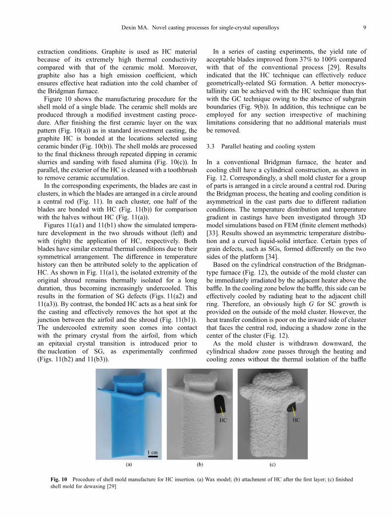
extraction conditions. Graphite is used as HC materialbecause of its extremely high thermal conductivitycompared with that of the ceramic mold. Moreover,graphite also has a high emission coefficient, whichensures effective heat radiation into the cold chamber ofthe Bridgman furnace.Figure 10 shows the manufacturing procedure for the
shell mold of a single blade. The ceramic shell molds areproduced through a modified investment casting proce-dure. After finishing the first ceramic layer on the waxpattern (Fig. 10(a)) as in standard investment casting, thegraphite HC is bonded at the locations selected usingceramic binder (Fig. 10(b)). The shell molds are processedto the final thickness through repeated dipping in ceramicslurries and sanding with fused alumina (Fig. 10(c)). Inparallel, the exterior of the HC is cleaned with a toothbrushto remove ceramic accumulation.In the corresponding experiments, the blades are cast in
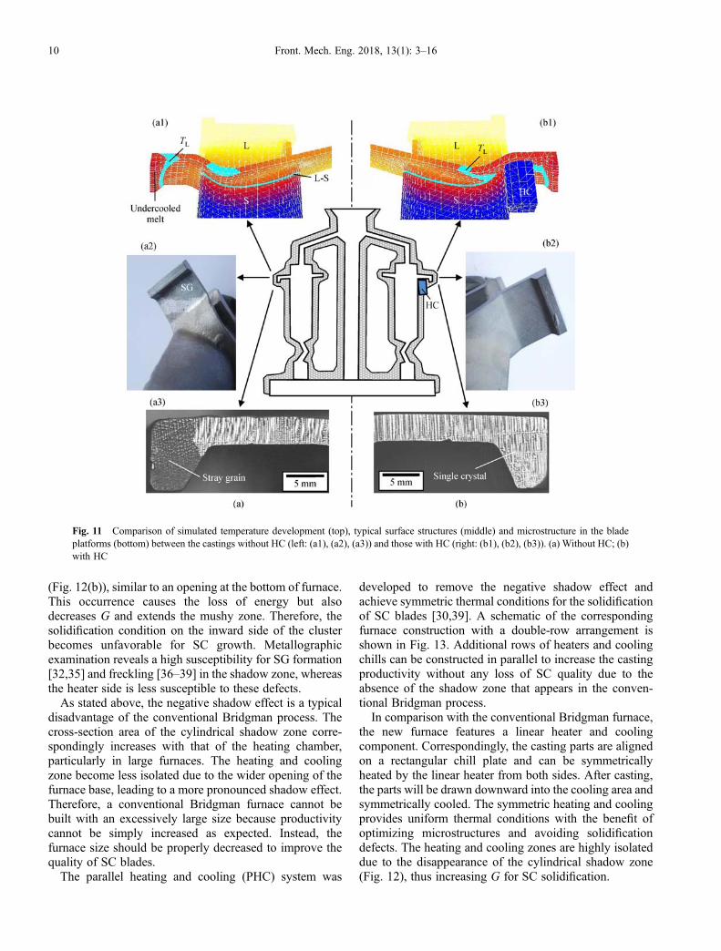
clusters, in which the blades are arranged in a circle arounda central rod (Fig. 11). In each cluster, one half of theblades are bonded with HC (Fig. 11(b)) for comparisonwith the halves without HC (Fig. 11(a)).Figures 11(a1) and 11(b1) show the simulated tempera-
ture development in the two shrouds without (left) andwith (right) the application of HC, respectively. Bothblades have similar external thermal conditions due to theirsymmetrical arrangement. The difference in temperaturehistory can then be attributed solely to the application ofHC. As shown in Fig. 11(a1), the isolated extremity of theoriginal shroud remains thermally isolated for a longduration, thus becoming increasingly undercooled. Thisresults in the formation of SG defects (Figs. 11(a2) and11(a3)). By contrast, the bonded HC acts as a heat sink forthe casting and effectively removes the hot spot at thejunction between the airfoil and the shroud (Fig. 11(b1)).The undercooled extremity soon comes into contactwith the primary crystal from the airfoil, from whichan epitaxial crystal transition is introduced prior tothe nucleation of SG, as experimentally confirmed(Figs. 11(b2) and 11(b3)).
In a series of casting experiments, the yield rate ofacceptable blades improved from 37% to 100% comparedwith that of the conventional process [29]. Resultsindicated that the HC technique can effectively reducegeometrically-related SG formation. A better monocrys-tallinity can be achieved with the HC technique than thatwith the GC technique owing to the absence of subgrainboundaries (Fig. 9(b)). In addition, this technique can beemployed for any section irrespective of machininglimitations considering that no additional materials mustbe removed.
3.3 Parallel heating and cooling system
In a conventional Bridgman furnace, the heater andcooling chill have a cylindrical construction, as shown inFig. 12. Correspondingly, a shell mold cluster for a groupof parts is arranged in a circle around a central rod. Duringthe Bridgman process, the heating and cooling condition isasymmetrical in the cast parts due to different radiationconditions. The temperature distribution and temperaturegradient in castings have been investigated through 3Dmodel simulations based on FEM (finite element methods)[33]. Results showed an asymmetric temperature distribu-tion and a curved liquid-solid interface. Certain types ofgrain defects, such as SGs, formed differently on the twosides of the platform [34].Based on the cylindrical construction of the Bridgman-
type furnace (Fig. 12), the outside of the mold cluster canbe immediately irradiated by the adjacent heater above thebaffle. In the cooling zone below the baffle, this side can beeffectively cooled by radiating heat to the adjacent chillring. Therefore, an obviously high G for SC growth isprovided on the outside of the mold cluster. However, theheat transfer condition is poor on the inward side of clusterthat faces the central rod, inducing a shadow zone in thecenter of the cluster (Fig. 12).As the mold cluster is withdrawn downward, the
cylindrical shadow zone passes through the heating andcooling zones without the thermal isolation of the baffle
Fig. 10 Procedure of shell mold manufacture for HC insertion. (a) Wax model; (b) attachment of HC after the first layer; (c) finishedshell mold for dewaxing [29]
Dexin MA. Novel casting processes for single-crystal superalloys 9
(Fig. 12(b)), similar to an opening at the bottom of furnace.This occurrence causes the loss of energy but alsodecreases G and extends the mushy zone. Therefore, thesolidification condition on the inward side of the clusterbecomes unfavorable for SC growth. Metallographicexamination reveals a high susceptibility for SG formation[32,35] and freckling [36–39] in the shadow zone, whereasthe heater side is less susceptible to these defects.As stated above, the negative shadow effect is a typical
disadvantage of the conventional Bridgman process. Thecross-section area of the cylindrical shadow zone corre-spondingly increases with that of the heating chamber,particularly in large furnaces. The heating and coolingzone become less isolated due to the wider opening of thefurnace base, leading to a more pronounced shadow effect.Therefore, a conventional Bridgman furnace cannot bebuilt with an excessively large size because productivitycannot be simply increased as expected. Instead, thefurnace size should be properly decreased to improve thequality of SC blades.The parallel heating and cooling (PHC) system was
developed to remove the negative shadow effect andachieve symmetric thermal conditions for the solidificationof SC blades [30,39]. A schematic of the correspondingfurnace construction with a double-row arrangement isshown in Fig. 13. Additional rows of heaters and coolingchills can be constructed in parallel to increase the castingproductivity without any loss of SC quality due to theabsence of the shadow zone that appears in the conven-tional Bridgman process.In comparison with the conventional Bridgman furnace,
the new furnace features a linear heater and coolingcomponent. Correspondingly, the casting parts are alignedon a rectangular chill plate and can be symmetricallyheated by the linear heater from both sides. After casting,the parts will be drawn downward into the cooling area andsymmetrically cooled. The symmetric heating and coolingprovides uniform thermal conditions with the benefit ofoptimizing microstructures and avoiding solidificationdefects. The heating and cooling zones are highly isolateddue to the disappearance of the cylindrical shadow zone(Fig. 12), thus increasing G for SC solidification.
Fig. 11 Comparison of simulated temperature development (top), typical surface structures (middle) and microstructure in the bladeplatforms (bottom) between the castings without HC (left: (a1), (a2), (a3)) and those with HC (right: (b1), (b2), (b3)). (a) Without HC; (b)with HC
10 Front. Mech. Eng. 2018, 13(1): 3–16

Preliminary experiments with the PHC system havebeen performed in a pilot furnace with a single rowarrangement. The casting cluster was linearly arranged sothat both sides of a shell mold can be symmetrically heatedin the heating zone and cooled in the cooling zone. For thecasting experiments, the superalloy IN939 was selectedowing to its strong tendency to form SGs [28]. The alloymelt was poured into the preheated shell mold mounted onthe chill plate and then withdrawn from the hot zoneinto the cold zone through the baffle at a velocity of3.0 mm/min. Corresponding experiments were conductedin a conventional furnace for comparison.As expected, minimizing or eliminating the asymmetric
thermal condition effectively suppressed SG formation.Few SGs were found in the specimens fabricated throughthe PHC system. Both sides of the specimens showed aminimal tendency for SG formation because of theimproved symmetry of the thermal conditions. The SGratio of the specimens significantly decreased from 49% to6% compared with those of the specimens fabricatedthrough the conventional Bridgman process [39]. Theseresults confirmed the feasibility of the PHC system forimproving the quality of SC components.
3.4 Dipping and heaving technology
A reasonably high temperature gradient for SC solidifica-tion is difficult to maintain with in the conventionalBridgman process because of the following reasons:(1) Ineffective radiative heat exchange, (2) unclosed baffleisolation between heating and cooling zones, and (3) highthermal resistance of the thick ceramic molds. Dipping andheaving (D&H) technology, also previously called thinshell casting [40] or downward directional solidificationprocess [41], was developed [30,39] to mitigate theselimitations. At the beginning of the D&H process, asshown in Fig. 14(a), a superalloy melt is overheated to astable temperature in a crucible and covered with hollowceramic beads, which function as a dynamic baffle. Theceramic mold, which has a selector (or an SC seed)connected to a chill at the top end, is dipped into the alloymelt through the dynamic baffle. To prevent the bafflebeads from entering the mold, the bottom end of the moldis sealed by a stopper made from the same alloy. When thestopper has melted, the alloy melt flows into the mold andcomes into contact with the chill-plate, leading to thenucleation of randomly oriented grains on the chill-
Fig. 12 Sketch of the cylindrical Bridgman furnace currentlyused for manufacturing SC blade clusters. (a) Transverse section;(b) longitudinal section
Fig. 13 Sketch of the PHC system. (a) Transverse section; (b)longitudinal section
Dexin MA. Novel casting processes for single-crystal superalloys 11

plate and the competitive growth of columnar grains(Fig. 14(b)). When a relatively stable thermal condition isreached, the mold is pulled up from the melt bath at aspecified withdrawal rate. SC growth will then occurthrough the grain selector during the downward solidifica-tion process of the blade (Fig. 14(c)). The shell mold canbe additionally cooled by blowing inert gas as it is pulledup to provide greater heat extraction and enable fasterwithdrawal rates.In the D&H process, owing to the balanced hydrostatic
pressure exerted by the melt between the inside and outsideof the mold, the wall thickness of the molds can be reducedto only approximately 1 mm, which is merely used toretain the casting’s shape, as shown in Fig. 15.D&H technology has been employed to produce SC
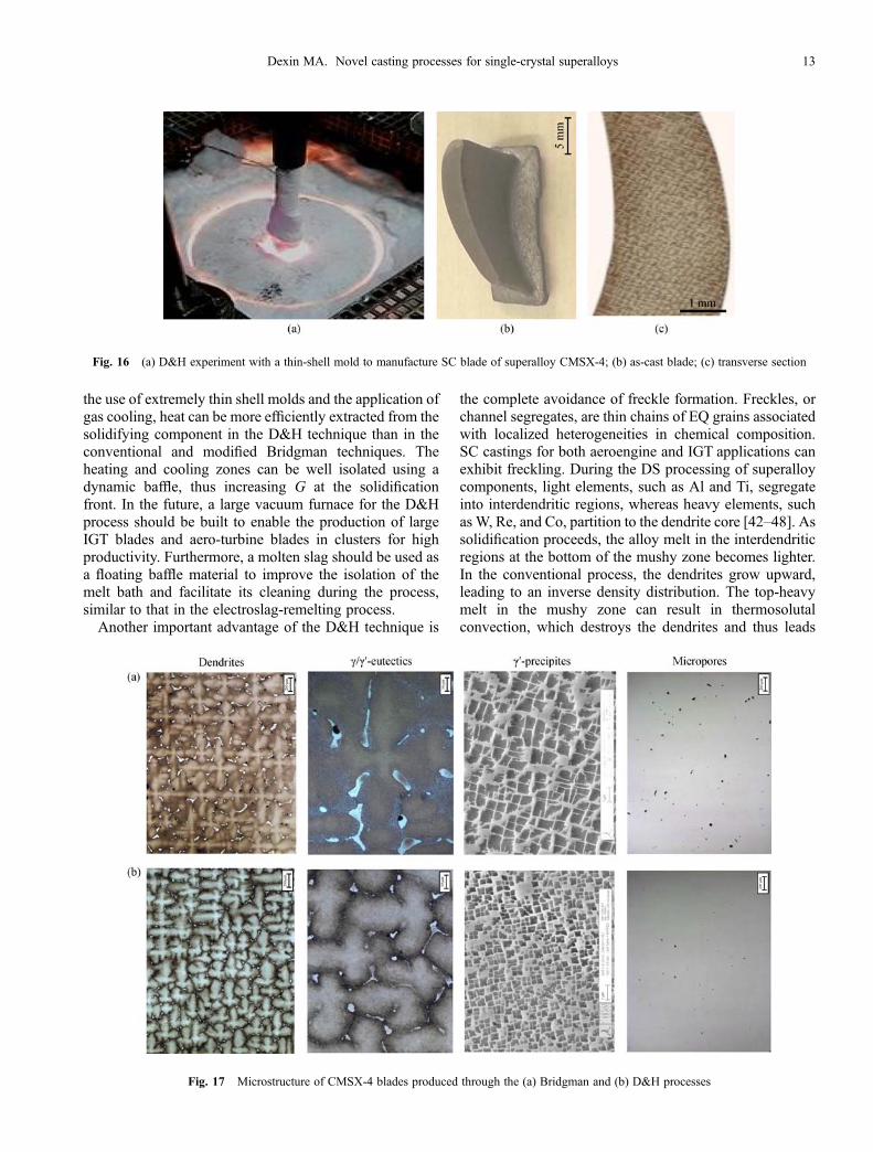
superalloy blades under protective argon gas [41,42]. AD&H experiment is illustrated in Fig. 16(a). In thisexperiment, a thin-shell mold is used to manufacture an SCsuperalloy blade. Figure 16(b) shows an SC bladefabricated from superalloy CMSX-4 through D&H and aseeding technique, exhibiting a refined dendrite structure(Fig. 16(c)).The thermal gradient G during solidification in the D&H
process was measured as approximately seven times higherthan in the conventional Bridgman process. A refinedmicrostructure was correspondingly obtained. The struc-tural parameters, such as the primary dendrite spacing, l1,the average size of the g/g′ eutectic pools and the g′precipitates, and the volume fraction of the micropores,significantly decreased, as shown in Fig. 17 and listed inTable 1. Given the refined structural scale of the material,
short diffusion distances are provided to homogenize thematerial, subsequently decreasing the solution treatmenttimes or enabling full solutioning during heat treatment forhighly alloyed materials. In addition, the g′ precipitatesproduced were more finely and homogeneously distributedand were thus more beneficial than those obtained throughthe current Bridgman process.The D&H technique has numerous advantages. Given
Fig. 14 Illustration of the D&H process. (a) Dipping the shell mold into the melt bath; (b) mold filling; (c) pulling up the mold to initiatedownward solidification
Fig. 15 (a) Wall thickness of the shell molds used for theproduction of turbine blades through the conventional Bridgmanprocess; (b) through the D&H process
12 Front. Mech. Eng. 2018, 13(1): 3–16
the use of extremely thin shell molds and the application ofgas cooling, heat can be more efficiently extracted from thesolidifying component in the D&H technique than in theconventional and modified Bridgman techniques. Theheating and cooling zones can be well isolated using adynamic baffle, thus increasing G at the solidificationfront. In the future, a large vacuum furnace for the D&Hprocess should be built to enable the production of largeIGT blades and aero-turbine blades in clusters for highproductivity. Furthermore, a molten slag should be used asa floating baffle material to improve the isolation of themelt bath and facilitate its cleaning during the process,similar to that in the electroslag-remelting process.Another important advantage of the D&H technique is
the complete avoidance of freckle formation. Freckles, orchannel segregates, are thin chains of EQ grains associatedwith localized heterogeneities in chemical composition.SC castings for both aeroengine and IGT applications canexhibit freckling. During the DS processing of superalloycomponents, light elements, such as Al and Ti, segregateinto interdendritic regions, whereas heavy elements, suchas W, Re, and Co, partition to the dendrite core [42–48]. Assolidification proceeds, the alloy melt in the interdendriticregions at the bottom of the mushy zone becomes lighter.In the conventional process, the dendrites grow upward,leading to an inverse density distribution. The top-heavymelt in the mushy zone can result in thermosolutalconvection, which destroys the dendrites and thus leads
Fig. 16 (a) D&H experiment with a thin-shell mold to manufacture SC blade of superalloy CMSX-4; (b) as-cast blade; (c) transverse section
Fig. 17 Microstructure of CMSX-4 blades produced through the (a) Bridgman and (b) D&H processes
Dexin MA. Novel casting processes for single-crystal superalloys 13
to the formation of freckle defects. The probability offreckling is strongly dependent on the composition of thealloy being cast. For example, third- or fourth-generationalloys rich in heavy elements, such as Re, are particularlyprone to this effect. In the D&H process, the interdendriticmelt becomes top-light due to the downward direction ofsolidification. Thus, the mushy zone is relatively stable,and the thermosolutal convection and the related freckledefects are essentially eliminated [49,50].
3.5 Precise control of SC growth through targeted coolingand heating
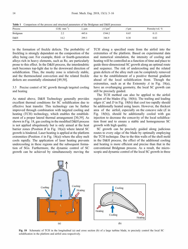
As stated above, D&H Technology generally providesexcellent thermal conditions for SC solidification due toeffective heat transfer. This technology can be furtherimproved through combination with targeted cooling andheating (TCH) technology, which enables the establish-ment of a proper lateral thermal arrangement [30,39]. Asshown in Fig. 18, gas cooling in the modified D&H processis not applied ubiquitously but is only aimed at the heatbarrier zones (Position B in Fig. 18(a)) where lateral SCgrowth is hindered. Laser heating is applied at the platformextremities (Position A in Fig. 18(a)) where the alloy meltcools rapidly. The application of laser heating preventsundercooling in these regions and the subsequent forma-tion of SGs. Furthermore, the dynamic control of SCgrowth can be achieved by simultaneously moving the
TCH along a specified route from the airfoil into theextremities of the platform. Based on experimental dataand numerical simulation, the intensity of cooling andheating will be controlled as a function of time and place toguide three-dimensional SC growth along an optimal routeand sequence. The risk of undercooling and the relatedgrain defects of the alloy melt can be completely removeddue to the establishment of a positive thermal gradientahead of the local solidification front. Though theextremities, such as at the Extremity A in Fig. 18(a),have an overhanging geometry, the local SC growth canstill be precisely guided.The TCH method can also be applied to the airfoil
region of the blades (Fig. 18(b)). The trailing and leadingedges (C and D in Fig. 18(b)) that cool too rapidly shouldbe additionally heated using lasers. However, the thickestarea of the airfoil, especially on the concave side (E inFig. 18(b)), should be additionally cooled with gasinjection to decrease the concavity of the local solidifica-tion front and to ensure a stable and homogeneous SCgrowth with high quality.SC growth can be precisely guided along judicious
routes to every edge of the blade by optimally employingthe TCH technique. Due to the thin walls of the shell moldin the D&H process, the effect of the additional coolingand heating is more efficient and precise than that in theconventional Bridgman process. As a result, the micro-scopic and dynamic control of the local SC growth in three
Table 1 Comparison of the process and structural parameters of the Bridgman and D&H processes
Process G/(K∙mm‒1) l1/μm γ/γ′/μm2 γ′/μm Porosity/vol. %
Bridgman 2.2 445.6 1544.2 0.65 0.13
D&H 14.2 299.3 346.9 0.30 0.02
Fig. 18 Schematic of TCH in the longitudinal (a) and cross section (b) of a large turbine blade, to precisely control the local SCsolidification in the platform and airfoil area respectively.
14 Front. Mech. Eng. 2018, 13(1): 3–16
dimensions can be achieved in addition to the significantimprovement in macroscopic cooling condition. Instead ofinjecting inert gas to strengthen the effectiveness of theprocess, dripping liquid Ar or He can be performed toachieve targeted cooling in this process.
4 Summary
This paper presents a brief review of the current castingtechniques for SC blades, as well as an analysis of thesolidification process in complex turbine blades. Toremove geometry-related grain defects, the GC and HCtechniques were developed to circumvent or minimize theheat barrier at the junction between the airfoil and theplatform. Blades fabricated through the HC techniqueexhibit excellent monocrystallinity owing to the absence ofsubgrain boundaries. The PHC system has been employedto achieve symmetric thermal conditions for the solidifica-tion of SC blades. In this system, both sides of a shell moldcan be symmetrically heated in the heating zone andcooled in the cooling zone. The negative shadow effect inthe current Bridgman process and its related defects arethereby significantly reduced. The major problems with theBridgman process, such as ineffective radiative heatexchange and high thermal resistance in the thick ceramicmolds, can be effectively resolved through the D&Htechnique and the use of thin-shell molds. A finemicrostructure can be obtained due to the establishmentof a high G at the solidification front. A new concept forthree-dimensional and precise control of SC growth wasproposed on the basis of the analysis of the solidificationprocess in complex turbine blades. The TCH techniquewas developed on the basis of this concept to establish aproper thermal arrangement for the microscopic control ofSC growth in the critical regions of large IGT blades. Thedynamic control of SC growth can be achieved bysimultaneously moving the TCH along a specified route.
Acknowledgements This work was funded by the Science and TechnologyInnovation Commission of Shenzhen Municipality (Grant No.JSGG20141016141652366) and the Economic, Trade and InformationCommission of Shenzhen Municipality (Grant No. 2016-122), the Programfor Guangdong Introducing Innovative and Enterpreneurial Teams.
Open Access This article is distributed under the terms of the CreativeCommons Attribution 4.0 International License (http://creativecommons.org/licenses/by/4.0/), which permits unrestricted use, distribution, and reproduc-tion in any medium, provided the appropriate credit is given to the originalauthor(s) and the source, and a link is provided to the Creative Commonslicense, indicating if changes were made.
References
1. Versnyder F L, Shank M E. The development of columnar grain and
single crystal high temperature materials through directional
solidification. Materials Science and Engineering, 1970, 6(4):
213–247
2. Pratt D C. Industrial casting of superalloys. Materials Science and
Technology, 1986, 2(5): 426–435
3. Quested P N, Osgerby S. Mechanical properties of conventionally
cast, directionally solidified and single-crystal superalloys. Materi-
als Science and Technology, 1986, 2(5): 461–475
4. Gebhardt A. Rapid Prototyping. Munich: Carl Hanser Verlag, 2006
5. Feriera J C, Santos E, Madureira H, et al. Integration of VP/RP/RT/
RE/RM for rapid product and process development. Rapid
Prototyping Journal, 2006, 12(1): 18–28
6. Budzik G, Markowski T, Sobolak M. Hybrid foundry patterns of
bevel gears. Archives of Foundry Engineering, 2007, 7(1): 131–134
7. Pattnaik S, Jha P K, Karunakar D B. A review of rapid prototyping
integrated investment casting processes. Proceedings of the
Institution of Mechanical Engineers, Part L: Journal of Materials
Design and Applications, 2014, 228(4): 249–277
8. Bridgman P W. US Patent, 1793672, 1931-02-24
9. Erickson J S, Owczarski W A, Curran P W. Process speeds up
directional solidification. Metal Progress, 1971, 99: 58–60
10. Pratt D C. Industrial casting of superalloys. Materials Science and
Technology, 1986, 2(5): 426–435
11. Elliott A J, Pollock T M, Tin S, et al. Directional solidification of
large superalloy castings with radiation and liquid-metal cooling: A
comparative assessment. Metallurgical and Materials Transactions
A: Physical Metallurgy and Materials Science, 2004, 35(10): 3221–
3231
12. Tschinkel J G, Giamei A F, Kearn B H. US Patent, 3763926, 1973-
10-09
13. Giamei A F, Tschinkel J G. Liquid metal cooling: A new
solidification technique. Metallurgical Transactions and Materials
Transactions A: Physical Metallurgy and Materials Science, 1976, 7
(9): 1427–1434
14. Elliott A J. Directional solidification of large cross-section Ni-base
superalloy castings via liquid-metal cooling. Dissertation for the
Doctoral Degree. Ann Arbor: The University of Michigan, 2005
15. Liu L, Huang T, Qu M, et al. High thermal gradient directional
solidification and its application in the processing of nickel-based
superalloys. Journal of Materials Processing Technology, 2010, 210
(1): 159–165
16. Zhang J, Luo L. Directional solidification assisted by liquid metal
cooling. Journal of Materials Science and Technology, 2007, 23:
289–300
17. Lohmüller A, Eßer W, Großmann J, et al. Improved quality and
economics of investment castings by liquid metal cooling—The
selection of cooling media. In: Proceedings of International
Symposium on Superalloys. 2000, 181–188
18. Konter M, Kats E, Hofmann N. A novel casting process for single
crystal gas turbine components. In: Proceedings of International
Symposium on Superalloys. 2000, 189–200
19. Wagner A, Shollock B A, McLean M. Grain structure development
in directional solidification of nickel-base superalloys. Materials
Science and Engineering A, 2004, 374(1–2): 270–279
20. Meyer ter Vehn M, Dedecke D, Paul U, et al. Undercooling related
casting defects in SC turbine blades. In: Proceedings of International
Symposium on Superalloys. 1996, 471–479
21. Zhou Y. Formation of stray grains during directional solidification
Dexin MA. Novel casting processes for single-crystal superalloys 15
of a nickel-based superalloy. Scripta Materialia, 2011, 65(4): 281–
284
22. Tschinkel J G, Giamei A F, Kearn B H. US Patent, 3763926, 1973-
10-09
23. Yang X L, Dong H B, WangW, et al. Microscale simulation of stray
grain formation in investment cast turbine blades. Materials Science
and Engineering: A, 2004, 386(1–2): 129–139
24. Xuan W, Ren Z, Liu H, et al. Formation of stray grains in
directionally solidified Ni-based superalloys with cross-section
change regions. Materials Science Forum, 2013, 747–748: 535–
539
25. Xuan W, Ren Z, Li C, et al. Formation of stray grain in cross section
area for Ni-based superalloy during directional solidification. IOP
Conference Series: Materials Science and Engineering, 2011, 27:
012035
26. Zhang J, Huang T, Liu L, et al. Advances in solidification
characteristics and typical casting defects in nickel-based single
crystal superalloys. Acta Metallurgica Sinica, 2015, 51(10): 1163–
1178 (in Chinese)
27. Xuan W, Ren Z, Li C. Experimental evidence of the effect of a high
magnetic field on the stray grains formation in cross-section change
region for Ni-based superalloy during directional solidification.
Metallurgical and Materials Transactions. A, Physical Metallurgy
and Materials Science, 2015, 46(4): 1461–1466
28. Ma D, Wu Q, Bührig-Polaczek A. Undercoolability of superalloys
and solidification defects in single crystal components. Advanced
Materials Research, 2011, 278: 417–422
29. Ma D, Bührig-Polaczek A. Application of heat-conductor technique
to production of SC turbine blade. Metallurgical and Materials
Transactions. B, Process Metallurgy and Materials Processing
Science, 2009, 40(5): 738–748
30. Ma D. Development of single crystal solidification technology for
production of superalloy turbine blades. Acta Metallurgica Sinica,
2015, 51(10): 1179–1190 (in Chinese)
31. Ma D, Bührig-Polaczek A. Avoiding grain defects in single crystal
components by application of a heat conductor technique. Interna-
tional Journal of Materials Research, 2009, 100(8): 1145–1151
32. Ma D, Bührig-Polaczek A. Development of heat conductor
technique for single crystal components of superalloys. International
Journal of Cast Metals Research, 2009, 22(6): 422–429
33. Yu J, Xu Q, Cui K, et al. Numerical simulation of solidification
process on single crystal Ni-based superalloy investment castings.
Journal of Materials Science and Technology, 2007, 23(1): 47–54
34. Napolitano R E, Schaefer R J. The convergence-fault mechanism for
low-angle boundary formation in single-crystal castings. Journal of
Materials Science, 2000, 35(7): 1641–1659
35. Ma D, Wu Q, Bührig-Polaczek A. Investigation on the asymmetry
of thermal condition and grain defect formation in customary
directional solidification process. IOP Conference Series: Materials
Science and Engineering, 2011, 27: 012037
36. Ma D, Wu Q, Bührig-Polaczek A. Some new observations on
freckle formation in directionally solidified superalloy components.
Metallurgical and Materials Transactions. B, Process Metallurgy
and Materials Processing Science, 2012, 43(2): 344–353
37. Ma D, Bührig-Polaczek A. The influence of surface roughness on
freckle formation in directionally solidified superalloy samples.
Metallurgical and Materials Transactions. B, Process Metallurgy
and Materials Processing Science, 2012, 43(4): 671–677
38. Ma D, Bührig-Polaczek A. The geometry effect of freckle formation
in the directionally solidified superalloy CMSX-4. Metallurgical and
Materials Transactions. A, Physical Metallurgy and Materials
Science, 2014, 45(3): 1435–1444
39. Ma D, Wang F, Wu Q, et al. Innovation of casting techniques for
single crystal turbine blades of superalloys. In: Proceedings of
International Symposium on Superalloys. 2016, 237–246
40. Ma D, Lu H, Bührig-Polaczek A. Experimental trials of the thin
shell casting (TSC) technology for directional solidification. IOP
Conference Series: Materials Science and Engineering, 2011, 27:
012036
41. Wang F, Ma D, Zhang J, et al. A high thermal gradient directional
solidification method for growing superalloy single crystals. Journal
of Materials Processing Technology, 2014, 214(12): 3112–3121
42. Wang F, Ma D, Bogner S, et al. Comparative investigation of the
downward and upward directionally solidified single-crystal blades
of superalloy CMSX-4. Metallurgical and Materials Transactions.
A, Physical Metallurgy and Materials Science, 2016, 47(5): 2376–
2386
43. Ma D, Grafe U. Dendrite growth and microsegregation during
directional solidification: An analytical model and experimental
studies on the superalloys CMSX-4. International Journal of Cast
Metals Research, 2000, 13(2): 85–92
44. Ma D, Grafe U. Microsegregation in directionally solidified
dendritic-cellular structure of superalloy CMSX-4. Materials
Science and Engineering A, 1999, 270(2): 339–342
45. Feng Q, Carroll L J, Pollock T M. Solidification segregation in
Ruthenium-containing nickel-base superalloys. Metallurgical and
Materials Transactions. A, Physical Metallurgy and Materials
Science, 2006, 37(6): 1949–1962
46. Caldwell E C, Fela F J, Fuchs G E. Segregation of elements in high
refractory content single crystal nickel based superalloys. In:
Proceedings of International Symposium on Superalloys. 2004.
811–818
47. Caldwell E C, Fela F J, Fuchs G E. The segregation of elements in
high-refractory-content single-crystal nickel-based superalloys.
Journal of Minerals, Metals and Materials, 2004, 56(9): 44–48
48. Heckl A, Rettig R, Singer R F. Solidification characteristics and
segregation behavior of nickel-base superalloys in dependence on
different rhenium and ruthenium contents. Metallurgical and
Materials Transactions. A, Physical Metallurgy and Materials
Science, 2010, 41(1): 202–211
49. Wang F, Ma D, Zhang J, et al. Investigation of segregation and
density profiles in the mushy zone of CMSX-4 superalloy solidified
during downward and upward directional solidification processes.
Journal of Alloys and Compounds, 2015, 620: 24–30
50. Wang F, Ma D, Bogner S, et al. Comparative study of the
segregation behavior and crystallographic orientation in a nickel-
based single-crystal superalloy. Journal of Alloys and Compounds,
2015, 647: 528–532
16 Front. Mech. Eng. 2018, 13(1): 3–16