Research Article ASemi ...
9
Hindawi Publishing Corporation International Journal of Vehicular Technology Volume 2012, Article ID 492105, 8 pages doi:10.1155/2012/492105 Research Article A Semi-Deterministic Channel Model for VANETs Simulations Jonathan Ledy, 1 Herv´ e Boeglen, 2 Anne-Marie Poussard, 1 Benoˆ ıt Hilt, 2 and Rodolphe Vauzelle 1 1 Laboratoire XLIM-SIC, UMR CNRS 6172, Universit´ e de Poitiers, 86034 Poitiers, France 2 Laboratoire MIPS-GRTC, Universit´ e de Haute Alsace, 68000 Colmar, France Correspondence should be addressed to Jonathan Ledy, [email protected] Received 15 October 2010; Revised 24 May 2011; Accepted 2 June 2011 Academic Editor: Athanasios Panagopoulos Copyright © 2012 Jonathan Ledy et al. This is an open access article distributed under the Creative Commons Attribution License, which permits unrestricted use, distribution, and reproduction in any medium, provided the original work is properly cited. Today’s advanced simulators facilitate thorough studies on Vehicular Ad hoc NETworks (VANETs). However the choice of the physical layer model in such simulators is a crucial issue that impacts the results. A solution to this challenge might be found with a hybrid model. In this paper, we propose a semi-deterministic channel propagation model for VANETs called UM-CRT. It is based on CRT (Communication Ray Tracer) and SCME—UM (Spatial Channel Model Extended—Urban Micro) which are, respectively, a deterministic channel simulator and a statistical channel model. It uses a process which adjusts the statistical model using relevant parameters obtained from the deterministic simulator. To evaluate realistic VANET transmissions, we have integrated our hybrid model in fully compliant 802.11 p and 802.11 n physical layers. This framework is then used with the NS-2 network simulator. Our simulation results show that UM-CRT is adapted for VANETs simulations in urban areas as it gives a good approximation of realistic channel propagation mechanisms while improving significantly simulation time. 1. Introduction Vehicular Ad hoc NETworks (VANETs) are a very promising research area interesting the scientific community, car man- ufacturers, and mobile telephony operators. Vehicular appli- cations should be thoroughly tested before they are deployed in the real world. Because the setup of experimental VANETs would imply huge investments, computer simulations are generally preferred. One of the major issues when using simulators for VANETs concerns the vehicular environment and therefore the realistic modeling of the wireless propagation channel. Indeed, there are still several problems linked to the impact of the mobility and the traffic density on channel statistics yet to solve, for example, packets loss, rate of flow, frequency correlation, and amplitude distribution. Many research and development works relating to rout- ing [1], communication robustness [2], and information dissemination in VANETs [3] show results obtained with simulations involving very basic radio propagation models available in simulation tools (Friis and two-ray ground models, e.g.). The consequence of the mobility on the physical layer is most of the time treated in a simplistic and consequently not quite realistic manner. This can lead to erroneous results [4]. Moreover, one finds very few effective and robust channel models which take into account the mobility and especially the transmission environment. From this, one can understand that the radio propagation model used by the network simulation tool is a key factor in MANETs (Mobile Ad Hoc NETworks) and particularly in the VANETs subclass. Developing a radio channel model, which would describe the realistic radio channel conditions as accurately as possible, has been a continuous challenge. This is precisely what this work addresses. There already exist reliable channel models which are customizable according to the environment [5], but most of them are dedicated to mobile telephony. In parallel, one finds research works presenting deterministic channel models [6, 7] which are based on ray-tracing or ray-launching methods which allow a realistic modeling of the channel. Unfortunately, these models require very high processing times. As far as VANETs are concerned, deterministic channel models are not suitable because of the high mobility, the
Transcript of Research Article ASemi ...

Hindawi Publishing CorporationInternational Journal of Vehicular TechnologyVolume 2012, Article ID 492105, 8 pagesdoi:10.1155/2012/492105
Research Article
A Semi-Deterministic Channel Model for VANETs Simulations
Jonathan Ledy,1 Herve Boeglen,2 Anne-Marie Poussard,1
Benoıt Hilt,2 and Rodolphe Vauzelle1
1 Laboratoire XLIM-SIC, UMR CNRS 6172, Universite de Poitiers, 86034 Poitiers, France2 Laboratoire MIPS-GRTC, Universite de Haute Alsace, 68000 Colmar, France
Correspondence should be addressed to Jonathan Ledy, [email protected]
Received 15 October 2010; Revised 24 May 2011; Accepted 2 June 2011
Academic Editor: Athanasios Panagopoulos
Copyright © 2012 Jonathan Ledy et al. This is an open access article distributed under the Creative Commons Attribution License,which permits unrestricted use, distribution, and reproduction in any medium, provided the original work is properly cited.
Today’s advanced simulators facilitate thorough studies on Vehicular Ad hoc NETworks (VANETs). However the choice of thephysical layer model in such simulators is a crucial issue that impacts the results. A solution to this challenge might be found witha hybrid model. In this paper, we propose a semi-deterministic channel propagation model for VANETs called UM-CRT. It is basedon CRT (Communication Ray Tracer) and SCME—UM (Spatial Channel Model Extended—Urban Micro) which are, respectively,a deterministic channel simulator and a statistical channel model. It uses a process which adjusts the statistical model using relevantparameters obtained from the deterministic simulator. To evaluate realistic VANET transmissions, we have integrated our hybridmodel in fully compliant 802.11 p and 802.11 n physical layers. This framework is then used with the NS-2 network simulator.Our simulation results show that UM-CRT is adapted for VANETs simulations in urban areas as it gives a good approximation ofrealistic channel propagation mechanisms while improving significantly simulation time.
1. Introduction
Vehicular Ad hoc NETworks (VANETs) are a very promisingresearch area interesting the scientific community, car man-ufacturers, and mobile telephony operators. Vehicular appli-cations should be thoroughly tested before they are deployedin the real world. Because the setup of experimental VANETswould imply huge investments, computer simulations aregenerally preferred.
One of the major issues when using simulators forVANETs concerns the vehicular environment and thereforethe realistic modeling of the wireless propagation channel.Indeed, there are still several problems linked to the impactof the mobility and the traffic density on channel statisticsyet to solve, for example, packets loss, rate of flow, frequencycorrelation, and amplitude distribution.
Many research and development works relating to rout-ing [1], communication robustness [2], and informationdissemination in VANETs [3] show results obtained withsimulations involving very basic radio propagation modelsavailable in simulation tools (Friis and two-ray groundmodels, e.g.). The consequence of the mobility on the
physical layer is most of the time treated in a simplistic andconsequently not quite realistic manner. This can lead toerroneous results [4]. Moreover, one finds very few effectiveand robust channel models which take into account themobility and especially the transmission environment.
From this, one can understand that the radio propagationmodel used by the network simulation tool is a key factorin MANETs (Mobile Ad Hoc NETworks) and particularlyin the VANETs subclass. Developing a radio channel model,which would describe the realistic radio channel conditionsas accurately as possible, has been a continuous challenge.This is precisely what this work addresses.
There already exist reliable channel models which arecustomizable according to the environment [5], but most ofthem are dedicated to mobile telephony. In parallel, one findsresearch works presenting deterministic channel models[6, 7] which are based on ray-tracing or ray-launchingmethods which allow a realistic modeling of the channel.Unfortunately, these models require very high processingtimes.
As far as VANETs are concerned, deterministic channelmodels are not suitable because of the high mobility, the

2 International Journal of Vehicular Technology
diversity of the environment encountered, and the highnumber of communicating nodes. The study of the higherlayers of the OSI model (in particular the Network andApplication layers) requires a low simulation time (i.e., acouple of minutes) in order to allow statistical analyseson large simulation series. To answer the challenge ofchannel modeling in VANETs, several works propose variousmethods which can be classified in two categories accordingto the research domain of their authors.
In the network community, Dhoutaut et al. [8] proposea propagation model based on Markov chains elements andreal world experiments which is able to generate packetlosses in a very realistic way. Later on, Han and Abu-Ghazaleh proposed another method based on Finite StateMarkov model [9]. These models are half-way betweenvery detailed models using ray-tracing with computationallyintensive algorithms and models using theoretical analysiswhere physical phenomena are only handled in an aggregatemanner. But according to the authors, their models are notyet able to make a clear relation with a real environment.
In the physical channel modeling community, onecan find different statistical channel models which havebeen derived from intensive measurement campaigns. Thestochastic parameters of these models are extracted from themeasurement data. It has been shown that the measuredamplitude samples follow Rice, Rayleigh, or Weibull distri-butions [10]. In the case of vehicular channels there existsuch type of channel models which have been designed byAcosta-Marum and Ingram for the validation of the 802.11pstandard [11, 12]. It is a classical tapped delay line Wide SenseStationary Uncorrelated Scattering (WSSUS) channel model.In [10], Sen and Matolak propose channel models whichtake into account the sudden appearance/disappearance ofscatterers (moving obstacles) by modeling them as first-order, two-state Markov chains. In [13] Keredal et al. proposea geometry-based stochastic MIMO model for Vehicle-to-Vehicle (V2V) communications. However, as stated byMolisch in [14], there is only a small amount of V2V channelmeasurements available which “does not allow the derivationof statistically significant statements about real-world V2Vchannels”. In conclusion, extreme care has to be taken whenchoosing and parameterizing available statistical channelmodels for VANETs.
Another fundamental topic in VANETs simulation con-cerns the mobility model used for simulations. Many works,like the working by Marfia et al. [15], show the importanceof realistic mobility models. Indeed, the use of nonspecificmobility models employed in VANETs simulations mayprovide bad results, because they ignore the typical behaviorof the nodes in this kind of network. In conclusion, acombination of realistic radio wave propagation modelsand realistic mobility models is a large step towards morerealistic simulation environments as shown by Gunes et al.[16]. In our work, the selected simulation tools are theVANET-specific mobility generator VanetMobiSim [17] andthe generic network simulation tool NS-2 [18].
The rest of this paper is organized as follows. InSection 2, we present the components of UM-CRT that are,respectively, the statistical SCME-UM model and the realistic
CRT simulator. In Section 3, we give a detailed presentationof our semi-deterministic model, UM-CRT. Our frameworkincluding implementation and the simulation of the 802.11standard is also presented in this section. Section 4 isdedicated to the evaluation of our model. Finally, Section 5concludes this paper and deals with future works.
2. Towards a Semi-Deterministic Model
Statistical and deterministic channel models are the twocommon ways to describe the radio channel behavior inVANETs simulations. In this section, we describe an exampleof each of these approaches: for the statistical one, the SpatialChannel Model Extended in its Urban Microenvironment(SCME-UM) is described and, for the deterministic one, theCommunication Ray Tracer (CRT) simulator is presented.We then analyze their main characteristics in order topropose a new semi-deterministic solution which benefitsfrom the advantages of these two classical approaches.This proposition is called UM-CRT because it is based onrespectively, SCME-UM and CRT.
2.1. The Spatial Channel Model Extended (SCME). TheSpatial Channel Model Extended (SCME) statistical channelmodel is an evolution of the 3GPP Spatial Channel Model(SCM) [19]. It has been developed within the EuropeanWINNER project [20] for the simulation of B3G systems.The SCM model is limited to the simulation of systems at2 GHz for a maximum transmission bandwidth of 5 MHz,whereas its extension, SCME for SCM Extended, allows forthe simulation of systems at 2 and 5 GHz for a maximumtransmission bandwidth of 100 MHz [21].
SCM and SCME are so-called geometric models forwhich scatterers are placed stochastically in the simulationscene. SCME considers clusters of scatterers. Each clustercorresponds to a resolvable path. Each path is made up ofseveral nonresolvable subpaths. Figure 1 is a typical exampleshowing the main geometrical parameters used by the modelwhere a Base Station (BS) antenna array communicates witha Mobile Station (MS) antenna array. This example showsonly one cluster labeled n. A subpath is also shown (labeledm).
SCME is a natively Multiple Input Multiple Output(MIMO) model. It allows for the simulation of three typesof environments: Urban Macrocell, Suburban Microcell(distance between MS and BS 3 km maximum), and UrbanMicrocell (distance between MS and BS of 1 km maximum).In the context of urban VANETs, because of intervehiculardistances less than one kilometer we have chosen the UrbanMicrocell (UM) environment. The authors of [21] provide aMatlab implementation of the SCME model [22] which wehave used in our framework. This piece of software generatesChannel Impulse Responses (CIR) which can then be used ina digital communication chain.
2.2. The Communication Ray Tracer (CRT) Simulator. Letus now describe the Communication Ray Tracer (CRT)software. It is a deterministic propagation simulator devel-oped by the Xlim-SIC laboratory from the University of

International Journal of Vehicular Technology 3
BS array
θBS
N
N
v
θn,m,AoA
θn,m,AoD
Δn,m,AoD
Δn,m,AoA
θv
ΩBS
δn,AoA
δn,AoD
MS array
BS array broadside
MS array broadside
Cluster n
MS directionof travel
Subpath m
θMS
ΩMS
Figure 1: Geometric parameters of the SCME model.
Poitiers (France) [23]. CRT is based on an optimized 3Ddeterministic ray-tracing method to model the propaga-tion of radio waves in real environments (outdoor andindoor). Thus, CRT takes into account all the characteristics(geometric and electric) of the environment and providesthe information about the multipath phenomenon, whereeach path is characterized by its attenuation, delay, angulardirections, phase shift, and polarization. In this way, weobtain a complete characterization of the narrow-band andwide-band channel. This provides a realistic approach ofthe multi-path propagation mechanisms. CRT has beenvalidated by several measurement campaigns [23] and willtherefore be considered as our reference.
Figure 2 shows an example of a multi-path propagationsimulation in a 3D urban environment using CRT. Eachwhite line is one path followed by the radio waves betweenthe transmitter and the receiver defined by a black circlein Figure 2. The CRT simulation procedure is as follows.Firstly, the user chooses an environment and places thecommunicating nodes into that scene. In a second stage, thenodes are associated with a moving trajectory. Then, CRTcalculates the CIRs for all the communicating nodes in thesimulation scenario.
In order to reduce the computation time in a context ofmobility, an optimization based on the stationarity propertyof the channel [24] has been studied. It has been shown thata stationarity area of 8 meters can be considered.
2.3. Basis of the Proposed Semi-Deterministic Model forVANETs. The presentation of the two previous modelsshows several key elements.
The SCME-UM statistical model is very efficient toproduce CIRs in environments modeled by several clustersplaced randomly in the scene. However, it does not take intoaccount the geometrical specificities of real environments.On the contrary, CRT is able to provide CIRs directlyconnected with the environment by a complete modeling ofthe interactions between radio waves and building. However,
Figure 2: A CRT simulation of multipath propagation in a realistic3D urban environment.
it necessitates an important computation time for eachCIR calculation. Therefore, for VANETs applications, whichintroduce the mobility for each node and a significant num-ber of possible radio links between the nodes in the network,a deterministic solution leads to a huge computation time.
To address this problem, we propose in this paper ahybridisation of the two models presented previously namedUM-CRT. Indeed, we will combine at the same time themajor wave propagation phenomena (existence or not of thedirect path) with its deterministic component and the lowcomputation time allowed by its statistical one.
3. The Semi-Deterministic Channel Model
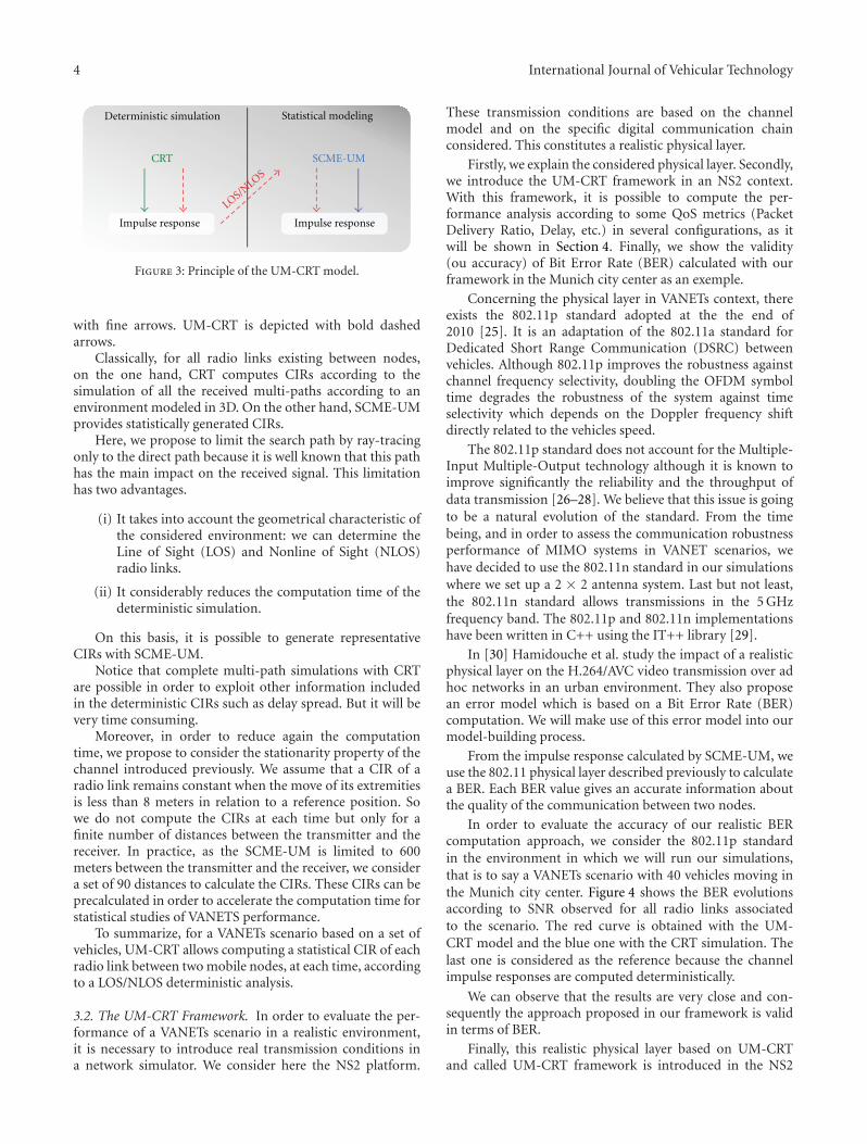
3.1. The UM-CRT Semi-Deterministic Channel Model. Ac-cording to the principle presented in the previous section,UM-CRT is created from the association of two models.Figure 3 shows the relationship between UM-CRT and bothCRT and SCME-UM, respectively, in the left and right parts
4 International Journal of Vehicular Technology
Deterministic simulation Statistical modeling
CRT SCME-UM
Impulse response Impulse response
LOS/NLOS
Figure 3: Principle of the UM-CRT model.
with fine arrows. UM-CRT is depicted with bold dashedarrows.
Classically, for all radio links existing between nodes,on the one hand, CRT computes CIRs according to thesimulation of all the received multi-paths according to anenvironment modeled in 3D. On the other hand, SCME-UMprovides statistically generated CIRs.
Here, we propose to limit the search path by ray-tracingonly to the direct path because it is well known that this pathhas the main impact on the received signal. This limitationhas two advantages.
(i) It takes into account the geometrical characteristic ofthe considered environment: we can determine theLine of Sight (LOS) and Nonline of Sight (NLOS)radio links.
(ii) It considerably reduces the computation time of thedeterministic simulation.
On this basis, it is possible to generate representativeCIRs with SCME-UM.
Notice that complete multi-path simulations with CRTare possible in order to exploit other information includedin the deterministic CIRs such as delay spread. But it will bevery time consuming.
Moreover, in order to reduce again the computationtime, we propose to consider the stationarity property of thechannel introduced previously. We assume that a CIR of aradio link remains constant when the move of its extremitiesis less than 8 meters in relation to a reference position. Sowe do not compute the CIRs at each time but only for afinite number of distances between the transmitter and thereceiver. In practice, as the SCME-UM is limited to 600meters between the transmitter and the receiver, we considera set of 90 distances to calculate the CIRs. These CIRs can beprecalculated in order to accelerate the computation time forstatistical studies of VANETS performance.
To summarize, for a VANETs scenario based on a set ofvehicles, UM-CRT allows computing a statistical CIR of eachradio link between two mobile nodes, at each time, accordingto a LOS/NLOS deterministic analysis.
3.2. The UM-CRT Framework. In order to evaluate the per-formance of a VANETs scenario in a realistic environment,it is necessary to introduce real transmission conditions ina network simulator. We consider here the NS2 platform.
These transmission conditions are based on the channelmodel and on the specific digital communication chainconsidered. This constitutes a realistic physical layer.
Firstly, we explain the considered physical layer. Secondly,we introduce the UM-CRT framework in an NS2 context.With this framework, it is possible to compute the per-formance analysis according to some QoS metrics (PacketDelivery Ratio, Delay, etc.) in several configurations, as itwill be shown in Section 4. Finally, we show the validity(ou accuracy) of Bit Error Rate (BER) calculated with ourframework in the Munich city center as an exemple.
Concerning the physical layer in VANETs context, thereexists the 802.11p standard adopted at the the end of2010 [25]. It is an adaptation of the 802.11a standard forDedicated Short Range Communication (DSRC) betweenvehicles. Although 802.11p improves the robustness againstchannel frequency selectivity, doubling the OFDM symboltime degrades the robustness of the system against timeselectivity which depends on the Doppler frequency shiftdirectly related to the vehicles speed.
The 802.11p standard does not account for the Multiple-Input Multiple-Output technology although it is known toimprove significantly the reliability and the throughput ofdata transmission [26–28]. We believe that this issue is goingto be a natural evolution of the standard. From the timebeing, and in order to assess the communication robustnessperformance of MIMO systems in VANET scenarios, wehave decided to use the 802.11n standard in our simulationswhere we set up a 2 × 2 antenna system. Last but not least,the 802.11n standard allows transmissions in the 5 GHzfrequency band. The 802.11p and 802.11n implementationshave been written in C++ using the IT++ library [29].
In [30] Hamidouche et al. study the impact of a realisticphysical layer on the H.264/AVC video transmission over adhoc networks in an urban environment. They also proposean error model which is based on a Bit Error Rate (BER)computation. We will make use of this error model into ourmodel-building process.
From the impulse response calculated by SCME-UM, weuse the 802.11 physical layer described previously to calculatea BER. Each BER value gives an accurate information aboutthe quality of the communication between two nodes.
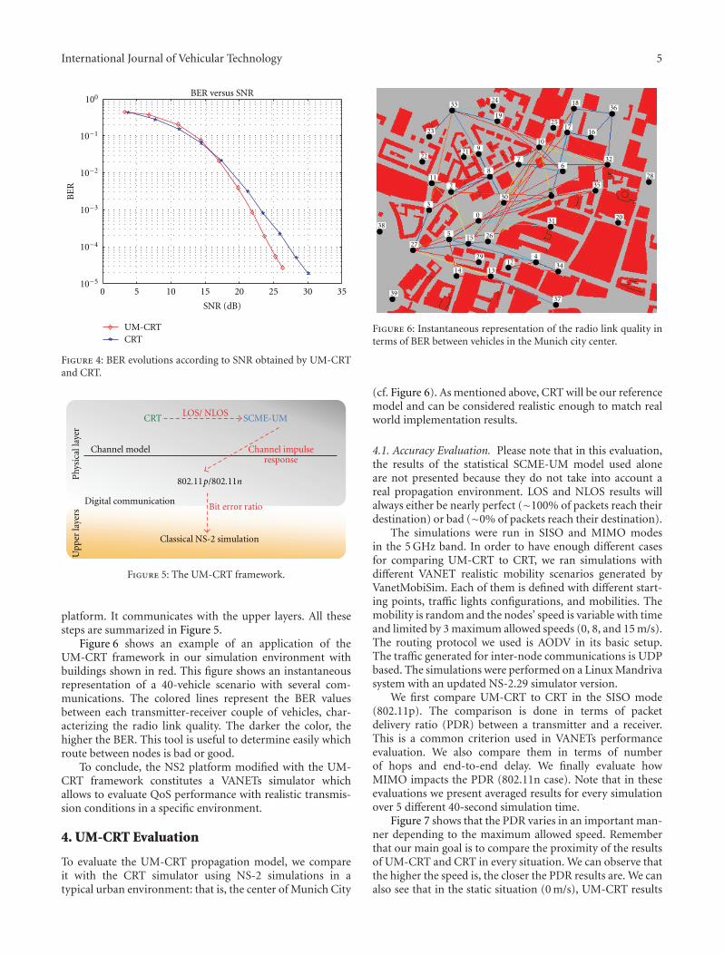
In order to evaluate the accuracy of our realistic BERcomputation approach, we consider the 802.11p standardin the environment in which we will run our simulations,that is to say a VANETs scenario with 40 vehicles moving inthe Munich city center. Figure 4 shows the BER evolutionsaccording to SNR observed for all radio links associatedto the scenario. The red curve is obtained with the UM-CRT model and the blue one with the CRT simulation. Thelast one is considered as the reference because the channelimpulse responses are computed deterministically.
We can observe that the results are very close and con-sequently the approach proposed in our framework is validin terms of BER.
Finally, this realistic physical layer based on UM-CRTand called UM-CRT framework is introduced in the NS2
International Journal of Vehicular Technology 5
0 5 10 15 20 25 30 35
100
10−1
10−2
10−3
10−4
10−5
SNR (dB)
BE
R
BER versus SNR
UM-CRTCRT
Figure 4: BER evolutions according to SNR obtained by UM-CRTand CRT.
CRT SCME-UMLOS/ NLOS
Classical NS-2 simulation
Upp
erla
yers
Phy
sica
llay
er
Channel impulseresponse
Channel model
802.11p/802.11n
Bit error ratioDigital communication
Figure 5: The UM-CRT framework.
platform. It communicates with the upper layers. All thesesteps are summarized in Figure 5.
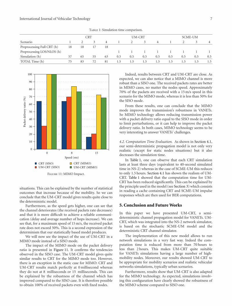
Figure 6 shows an example of an application of theUM-CRT framework in our simulation environment withbuildings shown in red. This figure shows an instantaneousrepresentation of a 40-vehicle scenario with several com-munications. The colored lines represent the BER valuesbetween each transmitter-receiver couple of vehicles, char-acterizing the radio link quality. The darker the color, thehigher the BER. This tool is useful to determine easily whichroute between nodes is bad or good.
To conclude, the NS2 platform modified with the UM-CRT framework constitutes a VANETs simulator whichallows to evaluate QoS performance with realistic transmis-sion conditions in a specific environment.
4. UM-CRT Evaluation
To evaluate the UM-CRT propagation model, we compareit with the CRT simulator using NS-2 simulations in atypical urban environment: that is, the center of Munich City
23
22
112
3
38
8
30
0
26155
27
39
14
29
1312
434
37
3324
19
21 9
76
10
2517
16
32
35
2031
28
3618
Figure 6: Instantaneous representation of the radio link quality interms of BER between vehicles in the Munich city center.
(cf. Figure 6). As mentioned above, CRT will be our referencemodel and can be considered realistic enough to match realworld implementation results.
4.1. Accuracy Evaluation. Please note that in this evaluation,the results of the statistical SCME-UM model used aloneare not presented because they do not take into account areal propagation environment. LOS and NLOS results willalways either be nearly perfect (∼100% of packets reach theirdestination) or bad (∼0% of packets reach their destination).
The simulations were run in SISO and MIMO modesin the 5 GHz band. In order to have enough different casesfor comparing UM-CRT to CRT, we ran simulations withdifferent VANET realistic mobility scenarios generated byVanetMobiSim. Each of them is defined with different start-ing points, traffic lights configurations, and mobilities. Themobility is random and the nodes’ speed is variable with timeand limited by 3 maximum allowed speeds (0, 8, and 15 m/s).The routing protocol we used is AODV in its basic setup.The traffic generated for inter-node communications is UDPbased. The simulations were performed on a Linux Mandrivasystem with an updated NS-2.29 simulator version.
We first compare UM-CRT to CRT in the SISO mode(802.11p). The comparison is done in terms of packetdelivery ratio (PDR) between a transmitter and a receiver.This is a common criterion used in VANETs performanceevaluation. We also compare them in terms of numberof hops and end-to-end delay. We finally evaluate howMIMO impacts the PDR (802.11n case). Note that in theseevaluations we present averaged results for every simulationover 5 different 40-second simulation time.
Figure 7 shows that the PDR varies in an important man-ner depending to the maximum allowed speed. Rememberthat our main goal is to compare the proximity of the resultsof UM-CRT and CRT in every situation. We can observe thatthe higher the speed is, the closer the PDR results are. We canalso see that in the static situation (0 m/s), UM-CRT results

6 International Journal of Vehicular Technology
0 8 150
10
20
30
40
50
60
70
80
90
100
CRTUM-CRT
Speed (ms)
Pack
etde
liver
yra
tio
(%)
Figure 7: UM-CRT PDR evaluation.
0
10
20
30
40
1 2 3 4
08
15
Speed (m/s)
Mobility situations
PD
Rdi
ffer
ence
(%)
Figure 8: UM-CRT versus CRT PDR in four mobility situations.
do not match the CRT reference results. Additionally, theknown negative influence of the speed on the PDR can beobserved in the 15 m/s part of the figure.
In Figure 8 we have a global view of the PDR differencebetween UM-CRT and CRT in several mobility situations.This confirms the similarity between UM-CRT and CRT andtherefore the realism of our semi-deterministic model whenwe are in nonstatic situations. In the cases with mobility, thedifference between the two models is less than 10%.
Figures 9 and 10 confirm that concerning the end-to-end delay and the average number of hops UM-CRT matchesbetter CRT; that is, it becomes more realistic, when the speedis higher. If we look further, the similarity between the twomodels can also be observed through an increasing delay andaverage number of hops that both increase when the speedincreases. For these two parameters, the difference betweenthe two models decreases above 0,1 seconds for the delay andcan be considered as very similar for the number of hops,when we are not in a static situation.
0 8 150
0.1
0.2
0.3
0.4
0.5
0.6
0.7
0.8
CRTUM-CRT
Speed (ms)
Del
ay(s
)
Figure 9: Delay evaluation.
0 8 150
0.5
1
1.5
2
2.5
3
3.5
4
CRTUM-CRT
Speed (ms)
Ave
rage
nu
mbe
rof
hop
s
Figure 10: Average number of hops evaluation.
Results have the same trend in the case of a static situationin the simulations. This is a current limitation of our modelwhich is not suitable for null speed. In this case, the LOS-NLOS criterion is not suitable alone to produce results thatmatch the deterministic model.
To summarize, when we are not in a static situation,the UM-CRT model gives results quite similar to CRT in all
International Journal of Vehicular Technology 7
Table 1: Simulation time comparison.
CRT UM-CRT SCME-UM
Scenario 1 2 3 4 1 2 3 4 1 2 3 4
Preprocessing Full CRT (h) 18 18 17 18
Preprocessing LOS/NLOS (h) 1 1 1 1 1 1 1 1
Simulation (h) 57 65 55 63 0.5 0.5 0.5 0.5 0.5 0.5 0.5 0.5
TOTAL Time (h) 75 83 72 81 1.5 1.5 1.5 1.5 1.5 1.5 1.5 1.5
0 8 150
10
20
30
40
50
60
70
80
90
100
Speed (ms)
Pack
etde
liver
yra
tio
(%)
CRT (SISO)UM-CRT (SISO)
CRT (MIMO)UM-CRT (MIMO)
Figure 11: MIMO Impact.
situations. This can be explained by the number of statisticaloutcomes that increase because of the mobility. So we canconclude that the UM-CRT model gives results quite close tothe deterministic model.
Furthermore, as the speed gets higher, one can see thatthe channel deteriorates (the received packets rate decreases)and that it is more difficult to achieve a reliable communi-cation (delay and average number of hops increase). We cansee that, for a maximum speed of 15 m/s, the received packetrate does not exceed 50%. This is a second expression of thedeterminism that our statistically based model produces.
We will now see the impact of the use of UM-CRT in aMIMO mode instead of a SISO mode.
The impact of the MIMO mode on the packet deliveryratio is presented in Figure 11. It confirms the tendenciesobserved in the SISO case. The UM-CRT model gives quitesimilar results to CRT for the MIMO mode too. However,there is an exception in the static case for MIMO: CRT andUM-CRT results match perfectly at 0 millisecond whereasthey do not at 8 milliseconds or 15 milliseconds. This canbe explained by the robustness of the channel which hasimproved compared to the SISO case. It is therefore possibleto obtain 100% of received packets even with fixed nodes.
Indeed, results between CRT and UM-CRT are close. Asexpected, we can also notice that a MIMO channel is morerobust than a SISO one. The received packets rates are betterin MIMO cases, no matter the nodes speed. Approximately70% of the packets are received with a 15 m/s speed in thisscenario for the MIMO mode, whereas it is less than 50% forthe SISO mode.
From these results, one can conclude that the MIMOmode improves the transmission’s robustness in VANETs.So MIMO technology allows reducing transmission powerwith a packet delivery ratio equal to the SISO mode in orderto limit perturbations, or it can help to improve the packetdelivery ratio. In both cases, MIMO technology seems to bevery interesting to answer VANETs’ challenges.
4.2. Computation Time Evaluation. As shown in Section 4.1,our semi-deterministic propagation model is not only veryrealistic (except for static nodes situations) but it alsodecreases the simulation time.
In Table 1, one can observe that each CRT simulationlasts at least three days (equivalent to 40-second simulatedtime in NS-2) whereas in the case of SCME-UM this reducesto only 1.5 hours. Section 4.1 has shown the realism of UM-CRT. Table 1 showed that the computation time for UM-CRT has been reduced significantly. This can be explained bythe principle used in the model (see Section 3) which consistsin reading a cache containing CRT and SCME-UM impulseresponses which are then used for BER computations.
5. Conclusion and Future Works
In this paper we have presented UM-CRT, a semi-deterministic channel propagation model for VANETs. UM-CRT, which was integrated into the NS-2 network simulator,is based on the stochastic SCME-UM model and thedeterministic CRT channel simulator.
The implementation of this new model allows to runnetwork simulations in a very fast way. Indeed the com-putation time is reduced from more than 70 hours toless than 2 hours. This makes UM-CRT quite suitablefor VANETs simulations having a large number of high-mobility nodes. Moreover, our results showed UM-CRT tobe appropriate for mobility scenarios and realistic vehicularnetworks simulations, typically urban scenarios.
Furthermore, results show that UM-CRT is also adaptedfor the MIMO technology. As expected, simulations involv-ing this configuration have clearly showed the robustness ofthe MIMO scheme compared to SISO one.

8 International Journal of Vehicular Technology
We currently focus our work on the selection of newrelevant criteria extracted from the CIR such as the RMSdelay spread or the link capacity.
References
[1] M. Boban, G. Misek, and O. K. Tonguz, “What is the bestachievable QoS for unicast routing in VANET?” in Proceedingsof the IEEE Globecom Workshops, pp. 1–10, New Oreleans, La,USA, December 2008.
[2] S. Y. Wang, “The effects of wireless transmission range onpath lifetime in vehicle-formed mobile ad hoc networks onhighways,” in Proceedings of the IEEE International Conferenceon Communications, vol. 5, pp. 3177–3181, Seoul, Korea, May2005.
[3] S. Yousefi, S. Bastani, and M. Fathy, “On the performance ofsafety message dissemination in vehicular ad hoc networks,” inProceedings of the 4th European Conference on Universal Mul-tiservice Networks, pp. 377–387, Toulouse, France, February2007.
[4] F. J. Martinez, C. K. Toh, J. C. Cano, C. T. Calafate, andP. Manzoni, “Realistic radio propagation models (RPMs) forVANET simulations,” in Proceedings of the IEEE Wireless Com-munications and Networking Conference, Budapest, Hungary,April 2009.
[5] 3GPP, “Spatial channel model for MIMO simulations,”TR 25.996 V9.0.0 (2009-12), http://www.3gpp.org/ftp/Specs/archive/25 series/25.996/25996-900.zip.
[6] I. Stepanov and K. Rothermel, “On the impact of a more real-istic physical layer on MANET simulations results,” Elsevier AdHoc Networks Journal, vol. 6, no. 1, pp. 61–78, 2006.
[7] R. Delahaye, A.-M. Poussard, Y. Pousset, and R. Vauzelle,“Propagation models and physical layer quality criteria influ-ence on ad hoc networks routing,” in Proceedings of the7th International Conference on Intelligent Transport SystemsTelecommunications, pp. 433–437, Sophia Antipolis, France,June 2007.
[8] D. Dhoutaut, A. Regis, and F. Spies, “Impact of radio prop-agation models in vehicular ad hoc networks simulations,”in Proceedings of the 3rd ACM International Workshop onVehicular Ad Hoc Networks (VANET ’06), pp. 40–49, LosAngeles, Calif, USA, September 2006.
[9] S. Han and N. B. Abu-Ghazaleh, “Estimated measurement-based Markov models: Towards flexible and accurate mod-eling of wireless channels,” in Proceedings of the 5th IEEEInternational Conference on Wireless and Mobile ComputingNetworking and Communication, pp. 331–337, Marrakech,Morocco, October 2009.
[10] I. Sen and D. W. Matolak, “Vehicle-vehicle channel models forthe 5-GHz band,” IEEE Transactions on Intelligent Transporta-tion Systems, vol. 9, no. 2, Article ID 4517519, pp. 235–245,2008.
[11] G. Acosta-Marum and M. A. Ingram, “A BER-based par-titioned model for a 2.4GHz vehicle-to-vehicle expresswaychannel,” Wireless Personal Communications, vol. 37, no. 3-4,pp. 421–443, 2006.
[12] G. Acosta-Marum and M. A. Ingram, “Six time- and freq-uency- selective empirical channel models for vehicularwireless LANs,” IEEE Vehicular Technology Magazine, vol. 2,no. 4, Article ID 4498409, pp. 4–11, 2007.
[13] J. Karedal, F. Tufvesson, N. Czink et al., “A geometry-basedstochastic MIMO model for vehicle-to-vehicle communica-tions,” IEEE Transactions on Wireless Communications, vol. 8,no. 7, pp. 3646–3657, 2009.
[14] A. F. Molisch, F. Tufvesson, J. Karedal, and C. F. Mecklen-brauker, “A survey on vehicle-to-vehicle propagation chan-nels,” IEEE Wireless Communications, vol. 16, no. 6, pp. 12–22,2009.
[15] G. Marfia, G. Pau, E. De Sena, E. Giordano, and M.Gerla, “Evaluating vehicle network strategies for downtownPortland: opportunistic infrastructure and the importance ofrealistic mobility models,” in Proceedings of the 5th Interna-tional Conference on Mobile Systems, Applications and Services,pp. 47–51, San Juan, Puerto Rico, USA, June 2007.
[16] M. Gunes, M. Wenig, and A. Zimmermann, “Realistic mobil-ity and propagation framework for MANET simulations,” inProceedings of the 6th International Conference on Networking,Atlanta, Ga, USA, 2007.
[17] J. Haerri, F. Filali, C. Bonnet, and M. Fiore, “VanetMobiSim:generating realistic mobility patterns for VANETs,” in Pro-ceedings of the 3rd ACM International Workshop on VehicularAd Hoc Networks (VANET ’06), Los Angeles, Calif, USA,September 2006.
[18] http://www.isi.edu/nsnam/ns.
[19] http://www.3gpp.org/ftp/Specs/html-info/25996.htm.
[20] http://www.ist-winner.org.
[21] D. S. Baum, J. Hansen, G. Del Galdo, M. Milojevic, J. Salo,and P. Kyosti, “An interim channel model for beyond-3Gsystems: extending the 3GPP spatial channel model (SCM),” inProceedings of the 61st Vehicular Technology Conference (VTC ’05), vol. 5, pp. 3132–3136, Stockholm, Sweden, June 2005.
[22] http://radio.tkk.fi/en/research/rf applications in mobilecommunication/radio channel/scme-2006-08-30.zip.
[23] F. Escarieu, V. Degardin, L. Aveneau et al., “3D modellingof the propagation in an indoor environment : a theoreticaland experimental approach,” in Proceedings of the EuropeanConference on Wireless Technologies (ECWT ’01), London, UK,September 2001.
[24] R. Delahaye, Simulation realiste et efficace de la couche physiquepour l’aide au routage des reseaux ad hoc, Ph.D. thesis,University of Poitiers, France, 2007.
[25] IEEE Standard for information technology—Telecommu-nications and information exchange between systems—Localand metropolitan area networks—Specific requirements, Part11: Wireless LAN Medium Acces Control (MAC) and Physicallayer (PHY) specifications, Amendment 6: Wireless Access inVehicular Environments, IEEE std 802.11p, 2010.
[26] G. J. Foschini, “Layered space-time architecture for wirelesscommunication in a fading environment when using multi-element antennas,” Bell Labs Technical Journal, vol. 1, no. 2,pp. 41–59, 1996.
[27] E. Telatar, “Capacity of multi-antenna Gaussian channels,”European Transactions on Telecommunications, vol. 10, no. 6,pp. 585–595, 1999.
[28] C. Oestges and B. Clerckx, MIMO Wireless Communications,Elsevier, 2007.
[29] http://sourceforge.net/apps/wordpress/itpp.
[30] W. Hamidouche, R. Vauzelle, C. Olivier, Y. Pousset, and C.Perrine, “Impact of realistic MIMO physical layer on videotransmission over mobile ad hoc network,” in Proceedings ofthe IEEE 20th Personal, Indoor and Mobile Radio Communica-tions Symposium (PIMRC ’ 09), Tokyo, Japan, September 2009.

International Journal of
AerospaceEngineeringHindawi Publishing Corporationhttp://www.hindawi.com Volume 2010
RoboticsJournal of
Hindawi Publishing Corporationhttp://www.hindawi.com Volume 2014
Hindawi Publishing Corporationhttp://www.hindawi.com Volume 2014
Active and Passive Electronic Components
Control Scienceand Engineering
Journal of
Hindawi Publishing Corporationhttp://www.hindawi.com Volume 2014
International Journal of
RotatingMachinery
Hindawi Publishing Corporationhttp://www.hindawi.com Volume 2014
Hindawi Publishing Corporation http://www.hindawi.com
Journal ofEngineeringVolume 2014
Submit your manuscripts athttp://www.hindawi.com
VLSI Design
Hindawi Publishing Corporationhttp://www.hindawi.com Volume 2014
Hindawi Publishing Corporationhttp://www.hindawi.com Volume 2014
Shock and Vibration
Hindawi Publishing Corporationhttp://www.hindawi.com Volume 2014
Civil EngineeringAdvances in
Acoustics and VibrationAdvances in
Hindawi Publishing Corporationhttp://www.hindawi.com Volume 2014
Hindawi Publishing Corporationhttp://www.hindawi.com Volume 2014
Electrical and Computer Engineering
Journal of
Advances inOptoElectronics
Hindawi Publishing Corporation http://www.hindawi.com
Volume 2014
The Scientific World JournalHindawi Publishing Corporation http://www.hindawi.com Volume 2014
SensorsJournal of
Hindawi Publishing Corporationhttp://www.hindawi.com Volume 2014
Modelling & Simulation in EngineeringHindawi Publishing Corporation http://www.hindawi.com Volume 2014
Hindawi Publishing Corporationhttp://www.hindawi.com Volume 2014
Chemical EngineeringInternational Journal of Antennas and
Propagation
International Journal of
Hindawi Publishing Corporationhttp://www.hindawi.com Volume 2014
Hindawi Publishing Corporationhttp://www.hindawi.com Volume 2014
Navigation and Observation
International Journal of
Hindawi Publishing Corporationhttp://www.hindawi.com Volume 2014
DistributedSensor Networks
International Journal of