Research Article A Novel Double-Piston Magnetorheological...
12
Research Article A Novel Double-Piston Magnetorheological Damper for Space Truss Structures Vibration Suppression Qiang Wang, 1 Mehdi Ahmadian, 2 and Zhaobo Chen 1 1 School of Mechatronics Engineering, Harbin Institute of Technology, Harbin 150001, China 2 Department of Mechanical Engineering, Center for Vehicle Systems and Safety, Virginia Polytechnic Institute and State University, Blacksburg, VA 24061, USA Correspondence should be addressed to Qiang Wang; [email protected] Received 10 March 2014; Revised 30 June 2014; Accepted 30 June 2014; Published 22 July 2014 Academic Editor: Nuno Maia Copyright © 2014 Qiang Wang et al. is is an open access article distributed under the Creative Commons Attribution License, which permits unrestricted use, distribution, and reproduction in any medium, provided the original work is properly cited. e design, fabrication, and testing of a new double-piston MR damper for space applications are discussed. e design concept for the damper is described in detail. e electromagnetic analysis of the design and the fabrication of the MR damper are also presented. e design analysis shows that the damper meets the weight and size requirements for being included in a space truss structure. e prototype design is tested in a damper dynamometer. e test results show that the damper can provide nearly 80 N of damping force at its maximum velocity and current. e test results also show that the seal drag could contribute significantly to the damping forces. Additionally, the test results indicate that both the work by the damper and damping force increase rapidly with increasing current at lower currents and taper off at higher currents as the damper starts to saturate. e damper force versus velocity plots show hysteresis in both pre- and postyield regions and asymmetric forces in jounce and rebound. A model is proposed for representing the force-displacement, force-velocity, and asymmetric forces observed in test results. A comparison of the modeling results and test data indicates that the model accurately represents the force characteristics of the damper. 1. Introduction is paper will address the application of magnetorheological (MR) dampers for space structures, such as a truss structure that can be folded on the ground and deployed in space. MR dampers use magnetorheological fluids that are able to change their rheological properties in the presence of a magnetic field. MR fluids have been suggested for a wide variety of applications. Among them, MR dampers (or shock absorbers) have proven to have the widest range of appli- cations, with the highest potential for commercialization. Some of the performance advantages of MR dampers include continuously controllable force, high dynamic bandwidth (rapid transition from one state to another), and low power consumption. Because of these advantages, MR dampers have been evaluated for a wide variety of applications such as commercial vehicle suspension systems [1–4], railway vehi- cles suspensions [5, 6], aircraſt landing gears [7–9], helicopter lead-lag dampers [10–13], operator seat suspensions [14, 15], seismic mitigation of buildings and bridges [16–20], and gun recoil control [21–23]. Past studies have shown that MR fluid can be used in any of the distinct dynamic modes shown in Figure 1: (i) valve or (flow) mode (Figure 1(a)), (ii) shear mode (Figure 1(b)), (iii) squeeze mode (Figure 1(c)). It is also possible to use the fluid such that two of above modes are combined. For instance, combining the valve mode and shear mode in a damper results in the arrangement illustrated in Figure 1(d). e most commonly used ones are the valve mode and valve and shear mode. e majority of the available MR dampers are based on a design that applies the fluid in one of the modes in Figure 1. As is shown schematically in Figure 2, the dampers can be single- or double-ended and include either an internal or external fluid passage that incorporates the electromagnet Hindawi Publishing Corporation Shock and Vibration Volume 2014, Article ID 864765, 11 pages http://dx.doi.org/10.1155/2014/864765
Transcript of Research Article A Novel Double-Piston Magnetorheological...

Research ArticleA Novel Double-Piston Magnetorheological Damper for SpaceTruss Structures Vibration Suppression
Qiang Wang1 Mehdi Ahmadian2 and Zhaobo Chen1
1 School of Mechatronics Engineering Harbin Institute of Technology Harbin 150001 China2Department of Mechanical Engineering Center for Vehicle Systems and Safety Virginia Polytechnic Institute and State UniversityBlacksburg VA 24061 USA
Correspondence should be addressed to Qiang Wang qiangwang1985gmailcom
Received 10 March 2014 Revised 30 June 2014 Accepted 30 June 2014 Published 22 July 2014
Academic Editor Nuno Maia
Copyright copy 2014 Qiang Wang et al This is an open access article distributed under the Creative Commons Attribution Licensewhich permits unrestricted use distribution and reproduction in any medium provided the original work is properly cited
The design fabrication and testing of a new double-piston MR damper for space applications are discussed The design conceptfor the damper is described in detail The electromagnetic analysis of the design and the fabrication of the MR damper are alsopresented The design analysis shows that the damper meets the weight and size requirements for being included in a space trussstructure The prototype design is tested in a damper dynamometer The test results show that the damper can provide nearly 80Nof damping force at its maximum velocity and currentThe test results also show that the seal drag could contribute significantly tothe damping forces Additionally the test results indicate that both the work by the damper and damping force increase rapidly withincreasing current at lower currents and taper off at higher currents as the damper starts to saturateThedamper force versus velocityplots show hysteresis in both pre- and postyield regions and asymmetric forces in jounce and rebound A model is proposed forrepresenting the force-displacement force-velocity and asymmetric forces observed in test results A comparison of the modelingresults and test data indicates that the model accurately represents the force characteristics of the damper
1 Introduction
This paper will address the application ofmagnetorheological(MR) dampers for space structures such as a truss structurethat can be folded on the ground and deployed in spaceMR dampers use magnetorheological fluids that are ableto change their rheological properties in the presence of amagnetic field MR fluids have been suggested for a widevariety of applications Among them MR dampers (or shockabsorbers) have proven to have the widest range of appli-cations with the highest potential for commercializationSome of the performance advantages of MR dampers includecontinuously controllable force high dynamic bandwidth(rapid transition from one state to another) and low powerconsumption Because of these advantagesMRdampers havebeen evaluated for a wide variety of applications such ascommercial vehicle suspension systems [1ndash4] railway vehi-cles suspensions [5 6] aircraft landing gears [7ndash9] helicopterlead-lag dampers [10ndash13] operator seat suspensions [14 15]
seismic mitigation of buildings and bridges [16ndash20] and gunrecoil control [21ndash23]
Past studies have shown that MR fluid can be used in anyof the distinct dynamic modes shown in Figure 1
(i) valve or (flow) mode (Figure 1(a))(ii) shear mode (Figure 1(b))(iii) squeeze mode (Figure 1(c))
It is also possible to use the fluid such that two of abovemodes are combined For instance combining the valvemodeand shear mode in a damper results in the arrangementillustrated in Figure 1(d) The most commonly used ones arethe valve mode and valve and shear mode
The majority of the available MR dampers are based on adesign that applies the fluid in one of the modes in Figure 1As is shown schematically in Figure 2 the dampers can besingle- or double-ended and include either an internal orexternal fluid passage that incorporates the electromagnet
Hindawi Publishing CorporationShock and VibrationVolume 2014 Article ID 864765 11 pageshttpdxdoiorg1011552014864765
2 Shock and Vibration
MR fluidPressure
Flow
Magnetic field
(a)
DisplacementForce
MR fluid
Magnetic field
(b)
MR fluid
ForceDisplacement
Magnetic field
(c)
Displacement
PressureForce
MR fluid
Magnetic field
Flow
(d)
Figure 1 MR fluid flow modes (a) valve mode (b) shear mode (c) squeeze mode and (d) valve and shear mode
431 2
(a)
1 23
45
(b)
1 2 3 5 4 6 7
(1) Piston rod(2) Cylinder(3) Coil
(5) Piston seal(6) Floating piston(7) Accumulator(8) Piston guide(4) MR fluid
(c)
1 2 3 48 6 7
(1) Piston rod(2) Cylinder(3) Coil
(5) Piston seal(6) Floating piston(7) Accumulator(8) Piston guide(4) MR fluid
(d)
Figure 2 Available MR dampers designs (a) a double-ended valve and shear mode one (b) a double-ended bypass valve mode one (c) asingle-ended valve mode one and (d) a single-ended valve and shear mode one
needed for changing the fluidrsquos flow properties Past studieshave considered various configurations shown in Figure 2including a double-ended damper in valve and shear mode[6 18 21] a double-ended damper in valve mode with bypassvalve [19 20] a single-ended damper in valvemode [1 3ndash5 7ndash9 12 15ndash17] and a single-ended damper in valve and shearmode [2 22 23]
Figure 2(a) shows a double-ended valve and shear modeMR damper The coil is included within the damper pistonthat moves relative to the damper body The coil leads passthrough the piston rod and are connected to the electricalpower supply that is commonly placed outside of the damper
The magnetic flux generated by the electrical coil passesthrough the damper body and the fluid that is captured in thesmall gap between the body and piston closing the magneticfield around the piston This results in subjecting the MRfluid to a magnetic field with a flux density proportionalto the current passing through the coil The fluid flow isperpendicular to themagnetic field passing through the fluidMR fluid in this damper works in a combination of valvemode and shear mode Because the rod volume within thedamper body remains unchanged a double-ended damperhas a constant fluid chamber volume This is in contrastto a single-ended damper that has a variable fluid chamber
Shock and Vibration 3
volume depending on how far the damper rod is insertedinside the chamber In such cases a floating piston or a twin-tube design is used to accommodate the change in the fluidchamber volume while keeping it fully filled with MR fluid
Figure 2(b) shows a double-ended valve mode MRdamper with an external fluid passage to accommodate theflow between the chambers on the two sides of the pistonThe external tube enables incorporating an electrical coilfor passing a magnetic field through the MR fluid as itflows within the tube The fluid flow inside the passageis perpendicular to the magnetic field subjecting the MRdamper to valvemode In this design there is no gap betweenthe piston and damper cylinder and as such the fluid passesthrough a passage that is incorporated within the piston Aband seal with low coefficient of friction (commonly made ofTeflon material) is used to prevent any fluid leakage aroundthe piston Since the magnetic field does not pass throughthe damper body it can be made of nonmagnetic materialsThe external coil can provide a better dissipation of theheat generated by the electrical coil A disadvantage of thisdesign is the space needed for accommodating the externalpassageway
Figure 2(c) shows a single-ended valvemodeMRdamperwhere the MR fluid flow orifice is directly on the damperpistonThe coil is integrated inside of the pistonThe damperdesign is similar to the double-ended one in Figure 2(b)except that an accumulator is needed to compensate thechange in fluid chamber volume caused by the varying rodvolume that must be accommodated as the piston movesrelative to the damper body A high-pressure gas chamberseparated from the fluid chamber by a floating piston isincorporated in series with the fluid chamber to enablevarying the latter without causing any vacuumThe dampingforce reduces significantly if the damper cavitates due to thelowering of the boiling pressure of the fluid in vacuum
The final arrangement shown in Figure 2(d) is a single-ended valve and shear mode MR damper with an internalpiston guide to guarantee the alignment of damper pistonand cylinder This design is preferred because the piston andcoil are simpler and can be implemented more easily Theremaining aspects of the design are identical to the damperin Figure 2(c)
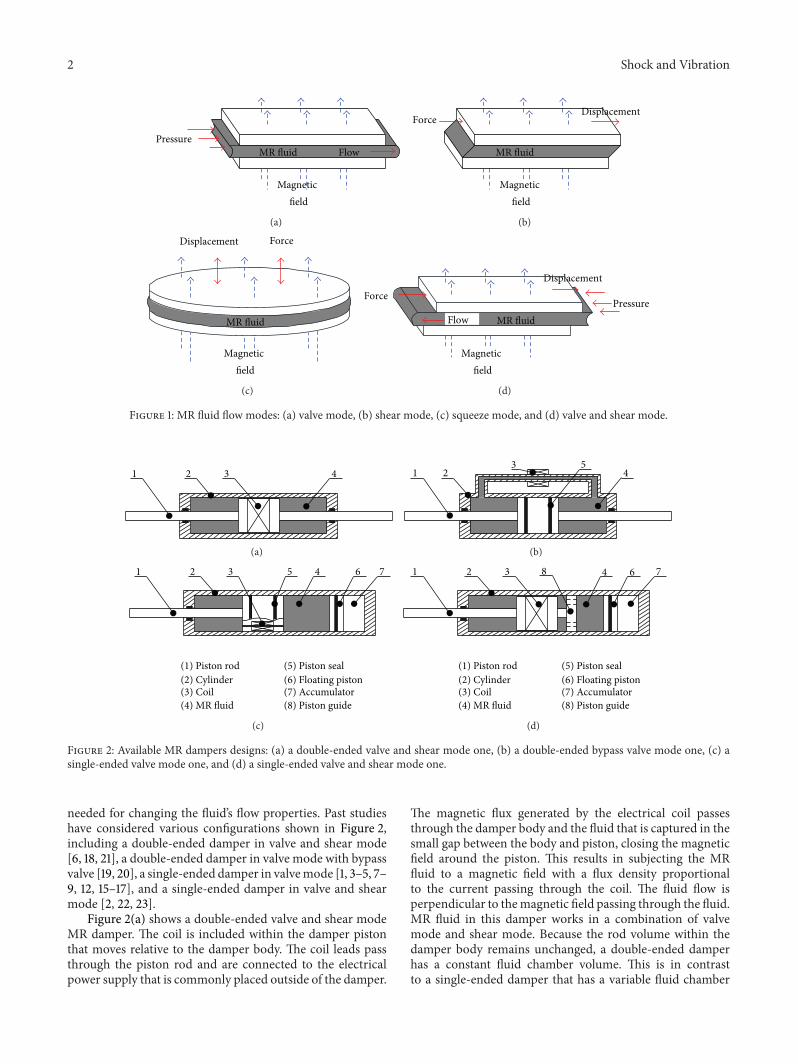
The space applications of MR dampers include thoseprovided in [24ndash28] As shown in Figure 3 the studies byOh et al provide an analysis of the benefits of a damperplaced at the base of the structure in place of one of the trussmembers for controlling the structural vibrations [24 25]In other similar studies by Dominguez et al the use of a MRdamper incorporated as one of the trussmembers is evaluatedfor controlling vibrations while the structure is excited indifferent planes by a shaker in the manner shown in Figure 4[26 27] A more recent study proposes replacing one of thetruss members with a MR damper [28] Simulation results in[28] confirm the effectiveness ofMR dampers for suppressingvibrations within the structure even in case of a truss failureThe results in [24ndash28] show thatMRdampers with semiactivecontrol are effective in suppressing vibrations in lightweightand flexible space truss structures It is important to note thatall of these studies recommend replacing one of the truss
String
Tip mass
ProcessorDisplacementof tip mass (u) On-off signal
Power supply
Load on damper (p)Elongation of damper (d)
z
x
y
MR fluid damper
Figure 3 The experimental setup for controlling vibrations of aspace truss using MR dampers installed at the root of the structure[24]
members with a MR damper which at times may not bepossible or desirable
Although the studies in [24ndash28] have documented theefficacy of MR dampers in controlling space structure vibra-tions they do not address the added weight to the structuredue to the MR damper As it is well known one of the criticalaspects of any space structure is its weight The added weightcreates both mission challenges with placing the heaviercargo into orbit as well as the dynamic effects caused by theheavier truss member MR dampers in Figure 2 can providelarge forces and long strokes but that comes at the expenseof a higher weight that for space systems is often the mostcritical factor It is not feasible to scale down the damperto the required size simply because the coil leads must gothrough a super small piston rod which physicallymay not beable to accommodate themThis study intends to address thischallenge by suggesting a MR damper with a novel structurethat can be incorporated into a space structure as a trussmember while maintaining the low weight requirementsthrough incorporating lighter elements and maintaining theMR damper volume to a minimum
2 Double-Piston MR Damper Concept
As shown in Figure 5 the proposed double-piston MRdamper has two dynamic seals in contrast to the singleincorporated in monotube dampers The two dynamic sealsare connected by a rigid rod that causes them to have the samemotion The rigid rod also incorporates a coil piston that isplaced midway on the rod as denoted by item 4 in Figure 5The volume of the MR fluid chamber remains unchanged asthe rod and all of the components rigidly connected to itmoveback and forth within the damper body therefore eliminatingthe need for an accumulator As the MR fluid flows fromone chamber to the opposite side through the annular orifice(item 10 in Figure 5) it experiences a flow resistance that isproportional to the magnetic flux field within the gap Thisresults in a damping force that changes directly proportionalto the electrical current supplied to the damper The damperworks in a combination of shear and valve mode The valve
4 Shock and Vibration
FilterControlPower amplifier
MR damper
LVDT tranducer
1
2
3
4
5
67
8
9
10
11
12
13
14 15
16
17
1819
20
X
YZ
Amplifier
Signal generator
Analyzer
Accelerometer
Accelerometer
Figure 4 Test setup for controlling vibrations in a space truss with MR dampers while excited by an electromagnetic shaker [26]
5 6 7
12119 10
21 3 4 8
(1) Left seal piston(2) Outer tube(3) Inner tube(4) Coil piston(5) Coil(6) MR fluid
(7) Right seal piston(8) Piston rod(9) Left chamber(10) Annular orifice(11) Magnetic flux path(12) Right chamber
Figure 5 Schematic configuration of the double-piston MR damper
mode can be controlled by the narrowing of the midsectionof the damper and also the outer diameter of the coil piston
If no magnetic field is applied the MR damper providesa relatively small damping force resulting from the viscosityof the MR fluid With no current supplied to the damper(referred to as ldquooff-staterdquo) the damping force is directly pro-portional to the fluid viscosity and the MR orifice is designedinto the damper and it cannot be changed in real timeWhenhowever current is supplied to the damper (referred to asldquoon-staterdquo) the damping force can be controlled in real time
due to the changing yield stress of the MR damper as itpasses through the MR orifice The drag forces from the twodynamic seals are present in both on- and off-statesThe sealsare designed such that the seal drag forces are much smallerthan the total damping force especially in on-state
The design shown in Figure 5 allows the use of nonmag-netic materials such as aluminum alloy or even plastic formajority of the damper parts of course except for the partsin the magnetic flux path the inner tube and coil pistonBeyond minimizing the damper weight it is desirable to
Shock and Vibration 5
Coil leadsLeft piston
Annular orifice
Outer tubeInner tube
Coil pistonCoilRight pistonSelf-sealing nut
Piston rod
Filling hole
Figure 6 MR damper prototype cross-section
Left piston
MR fluid
Coil piston
MR fluid
Right piston
Coil
Outer tube
Inner tube
Outer tube
Inner tube
MR fluid
Coil piston
Coil Effective gap length
1243e + 000 gt1308e + 0001177e + 000 1243e + 0001112e + 000 1177e + 0001046e + 000 1112e + 000
9157e minus 001 9811e minus 0019811e minus 001 1046e + 000
8502e minus 001 9157e minus 0017848e minus 001 8502e minus 0017194e minus 001 7848e minus 0016540e minus 001 7194e minus 0015886e minus 001 6540e minus 0015232e minus 001 5886e minus 0014578e minus 001 5232e minus 0013924e minus 001 4578e minus 0013270e minus 001 3924e minus 0012616e minus 001 3270e minus 0011962e minus 001 2616e minus 0011308e minus 001 1962e minus 0016540e minus 002 1308e minus 001lt2653e minus 008 6540e minus 002
Density plot |B| Tesla
Figure 7 Magnetic field analysis of the prototype damper
include sensors required for control into the design such asdisplacement and force sensors It is also possible to integratesprings inside of the fluid chamber in order to provide arestoring force that works in parallel to the damping force
The most unique aspect of the MR damper designdescribed here is its double-piston structure This featurewill not only bring a light self-weight but also allow thedamper to have a small exterior diameter The damper strokecan be made as long as needed by making the damper aslong as needed for a particular application The details of thedesign are further included in Chinese Patent number ZL2011104208698
3 Prototype Double-Piston MR Damper
A prototype damper based on the concept described earlierhas been designed and fabricated at the Center for VehicleSystems and Safety (CVeSS) of Virginia Polytechnic Instituteand State University (Virginia Tech) The prototypersquos cross-section is shown in Figure 6
The outer tube and seal pistons that house the dynamicseals are made of 6000 series aluminum The coil pistonand inner tube are made of 12L14 steal The outer tube isslightly heated before inserting the inner tube into itThe coilis wrapped on a lathe at very low speeds and the leads arepassed through the one side (in our case the left piston) to
the outside The damper is filled with MRF-122EG fluid fromLord Corporation through the filling hole in right pistondenoted in Figure 6 A self-sealing nut is used to lock the rodand piston in place and reduce the likelihood of fluid leakage
An important aspect of MR dampers is the design of theelectromagnet in terms of ensuring that the magnetic circuitdoes not reach saturation at higher electrical currents Ideallyone would aim for a nearly uniform magnetic flux densitythroughout the entire circuit For the design in Figures 6 acommercially available software called FEMM was used foranalyzing the distribution of the flux field density as shownin Figure 7 and shows the model of the prototype damperand magnetic field density distribution in annular orifice fora 05 Amp electric current passing through the coil whichincludes 110 turns of 28AWG coil wire The zoomed in areawithin the flowgap shows that the flux lines are perpendicularto the fluid flow The diagram further shows little leakagebetween the edges of the coil piston and the inner tube
Figure 8 shows the average flux density along the effectivegap for various electrical currents and gap sizes As the gapsize increases the average magnetic flux density decreasesdue to an increase in the magnetic field reluctance with aslow trend The relationship between average magnetic fluxdensity and gap size is approximately linear as shown inFigure 8(b) Figure 8(c) shows that the average magnetic fluxdensity increases as electrical current increases for a given
6 Shock and Vibration
00501
01502
02505
115
0
01
02
03
Mag
netic
flux
den
sity
(Tes
la)
01Gap size (mm)
Drive current (amps)
(a)
Mag
netic
flux
den
sity
(Tes
la)
005 01 015 020
005
01
015
02
025
03
Gap size (mm)
Drive current 05 amps(b)
02 04 06 08 1 12 140
005
01
015
02
025
03
Drive current (amps)
Mag
netic
flux
den
sity
(Tes
la)
Gap size 01016 mm
(c)
Figure 8 Average magnetic flux density along the effective gap length (a) various drive currents (from 01 amps to 15 amps) and various gapsizes (from 005mm to 023mm) (b) various gap sizes with drive current 05 amps and (c) various drive currents with gap size 01016mm(0004 in)
Right pistonCoilLeft piston Coil pistonSelf-sealing nut
Piston rod
Outer tubeCoil leads
(a) (b)
Figure 9 The fabricated prototype damper (a) parts and (b) assembly
gap size with a nonlinear trend that reaches a plateau athigher currentsThe plateau is caused by the saturation of themagnetic field at higher currents
The technical specifications for the prototype design aregiven in Table 1 The weight of the fabricated prototype
damper shown in Figure 9 is only 82 g and the outsidediameter of the damper is 16mm This design is far lighterthan earlier designs that we are aware of
Another excellent feature of the double-piston MRdamper is its simple appearance The damper is compact and
Shock and Vibration 7
Load cell
Double-piston MR damper
DC power source
Data acquisition system
Grippers
Figure 10 Experimental setup for the prototype damper
Table 1 Technical specifications of the prototype damper
Parameters Value (metric) Value (imperial)MRF-122EG
Viscosity 40∘C 0042 plusmn 0020 Pa-s mdashDensity 228ndash248 gcm3 mdashOperating temperature minus40 to +130∘C mdash
Outer tubeOuter diameter 15875mm 58 inInner diameter 14224mm 0560 inTotal length 1397mm 550 in
Inner tubeOuter diameter 14224mm 0560 inInner diameter 12573mm 0495 inTotal length 3556mm 140 in
Coil pistonOuter diameter 12370mm 0487 inLip width 508mm 020 inTotal length 2032mm 080 in
GapGap size 01016mm 0004 inEffective gap length 1016mm 040 in
CoilCore diameter 6858mm 0270 inLength 1016mm 040 inWire gauge mdash 28Number of turns 110 110
Maximum stroke 1524mm 060 inWeight 82 g 29 oz
includes no outside passages which is helpful for packagingand folding and unfolding of space structures Additionallythe damper can be designed in various lengths to accommo-date the size necessary for a given structure
4 Experimental Setup
The electromagnetic actuated (EMA) damper dynamometeris used for testing the prototype damper As shown in
0 100 200 300 400 500
0
20
40
60
80
Piston velocity (mms)
Forc
e (N
)
Without MRF
minus500 minus400 minus300 minus200 minus100
minus60
minus80
minus40
minus20
10Amps08Amps06Amps04Amps
02Amps01Amps00Amps
Figure 11 The prototype damper quasisteady tested force versusvelocity curves
Figure 10 the damper is mounted vertically in the test rigbetween a stationary head at the top and a moving actuatorat the bottom The tests are performed at a fixed amplitudeat various frequencies resulting in different peak-to-peakvelocities The resulting damper forces are measured by aload cell at the stationary head A DC power supply is usedto change the driving current to the damper The experi-ments are carried out at room temperature approximately 25degrees Celsius (77 degrees Fahrenheit)
5 Test Results
The test results are shown in Figures 11 and 12 The damperis tested at various relative displacements and velocities (asdescribed earlier) and with different currents supplied tothe damper Figure 11 shows the peak forces versus peak
8 Shock and Vibration
Piston displacement (mm)
Forc
e (N
)
0 2 4 6
0
20
40
60
80
Drive current
minus80
minus60
minus6
minus40
minus4 minus2
minus20
00A01A02A
04A08A
3556mms89Hzfrequency
Displacement 635mm peak velocity
(a)
Piston velocity (mms)0 100 200 300minus300 minus200 minus100
Forc
e (N
)
0
20
40
60
80
minus80
minus60
minus40
minus20
Drive current00A01A02A
04A08A
3556mms89Hzfrequency
Displacement 635mm peak velocity
(b)
Figure 12 Hysteresis curves comparison at different drive current Tested data (- - -) and reconstructed results from identified parameters(mdash) (a) force versus displacement hysteresis curves and (b) force versus velocity hysteresis curves
velocities for each of the 7 currents supplied to the damperThe figure also shows the damping force when the damperis empty in order to measure seal drag A comparison of thedamping force for no current and empty conditions indicatethat seal drag contributes significantly to the damping force atlower velocities and lower currents At higher velocities andwhen higher currents are applied to the damper the effect ofthe seal drag is far less The results in Figure 11 also show theviscous effect of the MR fluid versus the rheological changesresulting from magnetic field The damping force at 00 Ampis due to the viscous effect of the fluid Comparing this forcewith others at higher currents indicates the classical trendthat is often observed for MR dampers The damping forceat lower currents is dominated by the fluid viscosity while athigher currents it plays a less significant role Figure 11 alsoshows that the change in damping force at higher currentsbecomes less as the damper starts to saturate a phenomenonthat was discussed earlier The ratio between the maximumdamping at 10 Amp and the minimum damping at 00 Ampis approximately 2 1 Although this ratio is smaller than someof the larger MR damper designs it is quite expected for acompact design such as what is described in this study Thedamping forces shown in Figure 11 indicate that the dampercan satisfactorily damp out the dynamics of a relatively largesize space truss structure which will be the topic of a futurestudy
Figure 12 shows the damping performance for a completecycle for a sinusoidal input at 635mm at 89Hz resultingin a peak velocity of 3556mmsec The dashed lines are thetested data whereas the solid lines that closely trace the testdata are from a damper model that will be described laterFigure 12(a) shows force versus displacement which indicatesthe amount of work performed by the damper Figure 12(b)shows force versus velocity which is a measure of the energydissipated by the damper The results are plotted for variouscurrents ranging from 00 to 08 Figure 12(a) shows thatthe work performed by the damper increases with increasingcurrent initially at a faster rate and eventually at a slowerrate This trend is also observed in damping forces shownin Figure 12(a) and peak damping forces discussed earlierin Figure 11 Additionally Figure 12(b) shows the hysteresiswhich increases with increasing current The flatten portionof the hysteresis loops indicate that the damper is operating inthe postyield region of the fluid with the bend in each curvesignifying the transition from pre- to postyield region Onelast observation is that the damper exhibits a local hysteresisin compression at higher currents This is most likely causesby the shear characteristics of the MR fluid within the gap athigher shear strain rates The same hysteresis is not observedin rebound The damping characteristics in Figure 12 arein line with what is commonly observed in MR dam-pers
Shock and Vibration 9
6 Asymmetric Model
Various parametric models have been developed in the pastfor modeling the hysteretic characteristics of MR dampers[29] Parametric models usually assume that the MR damperhas a symmetric damper force response during one test cycleThe differences between the compression and rebound strokeare ignored A nonsymmetric Bouc-Wen model is suggestedfor dealing with the asymmetric damper force [30] Themethod uses a hysteresis variable that is a function of therelative velocity across the damper The asymmetry in thisresearch occurs in the preyield to postyield transform regionAnother asymmetric damping force generation (ADFG)algorithm is employed to generate the asymmetric dampingforce in compression and rebound from a symmetric MRdamper design [31]The generalizedmodel in [31] can be usedto characterize both the symmetric and asymmetric hystere-sis characteristics of the damper at various damper velocitiesincluding force asymmetry occurring in the preyield regionBecause the hysteresis occurs in both pre- and postyieldregions an alternative model is needed for the damper forcein Figure 12(b)
The hyperbolic tangent model that is often used to modelthe hysteresis characteristics is modified for the purpose ofthis study [32 33] The modified model is given by
119891 = (119888 + 1198881015840 sign (119891)) + (119896 + 1198961015840 sign (119891)) 119909
+ 120572 (tanh (120573 + 120575 sign (119909))) + (1198910+ 1198911015840
0
sign (119891)) (1)
where 119888 and 119896 are the viscous and stiffness coefficients 120572 isthe scale factor of the hysteresis 120573 and 120575 are the hysteresisvariables given by the hyperbolic tangent function and 119891
0is
the damper force offset 1198881015840 1198961015840 and 11989110158400
are the modificationparameters respectively
To ensure that the force versus displacement and forceversus velocity curves transition smoothly at the force zerocrossing an additional constraint is imposed on the threevariables in which
1198881015840
0+ 1198961015840
1199090+ 1198911015840
0
= 0 (2)
where 0and 119909
0are the velocity and displacement when the
force crosses zeroThe asymmetric hyperbolic tangent model includes nine
parameters that is 119888 1198881015840 119896 1198961015840 120572 120573 120575 1198910 and 1198911015840
0
Butit only contains a simple hyperbolic tangent function andis computationally efficient in the context of parameteridentification The model uses the piston displacement andvelocity as input and calculates the damper force given by(1) and (2) The nine parameters are identified offline usinga nonlinear least square algorithm within the MATLABrsquosOptimization Toolbox
The identified parameters are shown in Table 2 Usingthe parameters estimated from the system identificationprocess the force versus piston displacement and velocitywas reconstructed and compared with the experimental datacurves In Figures 12(a) and 12(b) the solid lines that closelytrace the tested data (in dashed line) are from the model The
Table 2 Identified model parameters
Parameters Drive currents (A)00 A 01 A 02 A 04A 08A
119888 00364 00421 00394 00350 003381198881015840 00113 00012 00058 00030 00095119896 minus00020 minus00413 minus01307 minus02078 minus030551198961015840
minus00105 minus01021 minus01167 minus03276 minus02784120572 278907 428064 520225 594834 641797120573 00363 00273 00218 00201 00230120575 12543 11297 10351 10398 116481198910
minus27646 minus36630 minus40278 minus35516 minus649371198911015840
0
minus02350 minus04395 minus04275 minus01157 minus00181
comparison indicates that both the damper force slope andlocal hysteresis loop are represented accurately by the newmodel
7 Conclusions
The design fabrication and testing of a new double-pistonMR damper for space applications was discussed The designconcept for the damper was described in detail along withan overview of MR dampers for industrial and space appli-cations The fabrication of the MR damper and the detailsof the analysis of the electromagnetic aspects of the damperusing a commercially available software called FEMM wasalso described It was shown that it is possible to design thedamper such that it meets the weight and size requirementsfor being included in a space truss structure as one of thetruss members The FEMM analysis showed that the designof the coil and the remainder of the electromagnetic circuitare balanced in terms of the magnetic flux density whichthe model estimates to be approximately 025 Tesla at themaximum current of 10 Amp The prototype design is testedin a damper dynamometer using sinusoidal input at variousamplitudes and frequencies The test results show that thedamper can provide nearly 80N of damping force at itsmaximum velocity and currentThe ratio betweenmaximumdamping at 10 Amp and minimum damping at 00 Amp is2 1 which is believed to be sufficient for space applicationsalthough it is smaller than the MR dampers that are used forautomotive applicationsThe test results also showed that theseal drag could contribute significantly to the damping forcesparticularly at lower electrical currents
Evaluating the test results for a complete cycle thatcorresponds to damper velocity of 3556mmsec (Amplitude635mm frequency 89Hz) shows that the damper behavessimilar to its larger counterparts in terms of damper force risein pre- and postyield regions of the fluid saturation at highercurrents and hysteresis characteristics Evaluating damperforce versus displacement shows no cavitation of the damperThe plots follow the classical rectangular shapes with thearea under the curve representing the work performed by thedamper The work by the damper initially increases rapidlywith increasing current and tapers off at higher currents asthe damper starts to saturate The same characteristics are
10 Shock and Vibration
observed in damper force versus velocity plots The latterplots also show the hysteresis of the damper in both pre- andpostyield regions
A model that takes advantage of the models proposedfor MR dampers in earlier studies was proposed The modelwhich uses a hyperbolic tangent function includes a numberof coefficients that are found based on the damper test resultsThe model is intended to represent the force-displacementand force-velocity characteristics of the damper as well as theasymmetric forces observed in test results A comparison ofthe modeling results and test data indicated that the modelaccurately represents the force characteristic of the damper
Beyond this study that described the successful designfabrication and testing of theMR damper the authors intendto use the damper in a space structure and report on theeffects of the damper in reducing structural vibrations in afuture study
Conflict of Interests
The authors declare that there is no conflict of interestsregarding the publication of this paper
Acknowledgments
The first author expresses his gratitude to China ScholarshipCouncil (CSC) Financial support from CSC brought theopportunity for the first author to work in the Center forVehicle Systems and Safety (CVeSS) at Virginia PolytechnicInstitute and State University This research was also finan-cially supported by the National Natural Science Foundationof China (Grant nos 10972065 and 11372083)Thanks are alsoextended to Michael Craft and Clement Nagode for theirvaluable assistance during the prototype damper testing
References
[1] H Lee and S Choi ldquoControl and response characteristics ofa magneto-rheological fluid damper for passenger vehiclesrdquoJournal of Intelligent Material Systems and Structures vol 11 no1 pp 80ndash87 2000
[2] M Ahmadian and C A Pare ldquoA quarter-car experimentalanalysis of alternative semiactive control methodsrdquo Journal ofIntelligent Material Systems and Structures vol 11 no 8 pp604ndash612 2000
[3] G Z Yao F F Yap G Chen W H Li and S H Yeo ldquoMRdamper and its application for semi-active control of vehiclesuspension systemrdquo Mechatronics vol 12 no 7 pp 963ndash9732002
[4] H Du K Y Sze and J Lam ldquoSemi-active 119867infin
control ofvehicle suspensionwithmagneto-rheological dampersrdquo Journalof Sound and Vibration vol 283 no 3ndash5 pp 981ndash996 2005
[5] W H Liao and D H Wang ldquoSemiactive vibration controlof train suspension systems via magnetorheological dampersrdquoJournal of IntelligentMaterial Systems and Structures vol 14 no3 pp 161ndash172 2003
[6] Y K Lau and W H Liao ldquoDesign and analysis of magne-torheological dampers for train suspensionrdquo Proceedings of theInstitution of Mechanical Engineers F Journal of Rail and RapidTransit vol 219 no 4 pp 261ndash276 2005
[7] Y T Choi and N M Wereley ldquoVibration control of a landinggear system featuring electrorheologicalmagnetorheologicalfluidsrdquo Journal of Aircraft vol 40 no 3 pp 432ndash439 2003
[8] D C Batterbee N D Sims R Stanway and Z WolejszaldquoMagnetorheological landing gear 1 a design methodologyrdquoSmart Materials and Structures vol 16 no 6 pp 2429ndash24402007
[9] DC BatterbeeND Sims R Stanway andMRennison ldquoMag-netorheological landing gear 2 Validation using experimentaldatardquo Smart Materials and Structures vol 16 no 6 pp 2441ndash2452 2007
[10] S Marathe F Gandhi and K W Wang ldquoHelicopter bladeresponse and aeromechanical stability with a magnetorheo-logical fluid based lag damperrdquo Journal of Intelligent MaterialSystems and Structures vol 9 no 4 pp 272ndash282 1998
[11] GMKamathNMWereley andMR Jolly ldquoCharacterizationof magnetorheological helicopter lag dampersrdquo Journal of theAmerican Helicopter Society vol 44 no 3 pp 234ndash248 1999
[12] W Hu N M Wereley L Chemouni and P C Chen ldquoSemi-active linear stroke magnetorheological fluid-elastic helicopterlag damperrdquo Journal of Guidance Control and Dynamics vol30 no 2 pp 565ndash575 2007
[13] W Hu and N M Wereley ldquoHybrid magnetorheological fluid-elastomeric lag dampers for helicopter stability augmentationrdquoSmart Materials and Structures vol 17 no 4 Article ID 0450212008
[14] Y T Choi and NMWereley ldquoBiodynamic responsemitigationto shock loads using magnetorheological helicopter crew seatsuspensionsrdquo Journal of Aircraft vol 42 no 5 pp 1288ndash12952005
[15] G J Hiemenz W Hu and N M Wereley ldquoSemi-active mag-netorheological helicopter crew seat suspension for vibrationisolationrdquo Journal of Aircraft vol 45 no 3 pp 945ndash953 2008
[16] S J Dyke B F Spencer Jr M K Sain and J D CarlsonldquoModeling and control of magnetorheological dampers forseismic response reductionrdquo Smart Materials and Structuresvol 5 no 5 pp 565ndash575 1996
[17] S J Dyke B F Spencer Jr M K Sain and J D CarlsonldquoAn experimental study of MR dampers for seismic protectionrdquoSmart Materials and Structures vol 7 no 5 pp 693ndash703 1998
[18] G Yang B F Spencer Jr J D Carlson and M K Sain ldquoLarge-scale MR fluid dampers modeling and dynamic performanceconsiderationsrdquo Engineering Structures vol 24 no 3 pp 309ndash323 2002
[19] Q Sun L Zang J Zhou and Q Shi ldquoExperimental study ofthe semi-active control of building structures using the shakingtablerdquo Earthquake Engineering and Structural Dynamics vol 32no 15 pp 2353ndash2376 2003
[20] A Rodrıguez F Pozo A Bahar L Acho Y Vidal and JRodellar ldquoForce-derivative feedback semi-active control ofbase-isolated buildings using large-scale MR fluid dampersrdquoStructural Control amp Health Monitoring vol 19 no 1 pp 120ndash145 2012
[21] M Ahmadian and J C Poynor ldquoAn evaluation of magnetorheological dampers for controlling gun recoil dynamicsrdquo Shockand Vibration vol 8 no 3-4 pp 147ndash155 2001
[22] H Hu X Jiang J Wang and Y Li ldquoDesign modeling andcontrolling of a large-scale magnetorheological shock absorberunder high impact loadrdquo Journal of Intelligent Material Systemsand Structures vol 23 no 6 pp 635ndash645 2012
Shock and Vibration 11
[23] Z C Li and J Wang ldquoA gun recoil system employing a mag-netorheological fluid damperrdquo Smart Materials and Structuresvol 21 no 10 Article ID 105003 2012
[24] H U Oh and J Onoda ldquoAn experimental study of a semiactivemagneto-rheological fluid variable damper for vibration sup-pression of truss structuresrdquo Smart Materials and Structuresvol 11 no 1 pp 156ndash162 2002
[25] H U Oh ldquoExperimental demonstration of an improvedmagneto-rheological fluid damper for suppression of vibrationof a space flexible structurerdquo SmartMaterials and Structures vol13 no 5 pp 1238ndash1244 2004
[26] A Dominguez R Sedaghati and I Stiharu ldquoSemi-active vibra-tion control of adaptive structures using magnetorheologicaldampersrdquo AIAA Journal vol 44 no 7 pp 1563ndash1571 2006
[27] A Dominguez R Sedaghati and I Stiharu ldquoModeling andapplication of MR dampers in semi-adaptive structuresrdquo Com-puters amp Structures vol 86 no 3ndash5 pp 407ndash415 2008
[28] L S Huo G B Song S Nagarajaiah and H Li ldquoSemi-activevibration suppression of a space truss structure using a faulttolerant controllerrdquo Journal of Vibration and Control vol 18 no10 pp 1436ndash1453 2012
[29] D H Wang and W H Liao ldquoMagnetorheological fluiddampers a review of parametric modellingrdquo Smart Materialsand Structures vol 20 no 2 Article ID 023001 2011
[30] NM Kwok Q P Ha M T Nguyen J Li and B Samali ldquoBouc-Wen model parameter identification for a MR fluid damperusing computationally efficient GArdquo ISA Transactions vol 46no 2 pp 167ndash179 2007
[31] E R Wang W J Wang H Wang R Subhash and C YSu ldquoDescribing asymmetric hysteretic F-V characteristics of aMR damper resulted form symmetric MR damperrdquo Journal ofNanjing Normal University vol 8 no 1 pp 1ndash6 2008
[32] NMKwokQ PHa THNguyen J Li and B Samali ldquoA novelhysteretic model for magnetorheological fluid dampers andparameter identification using particle swarm optimizationrdquoSensors and Actuators A Physical vol 132 no 2 pp 441ndash4512006
[33] I Sahin T Engin and S Cemeci ldquoComparison of some existingparametric models for magnetorheological fluid dampersrdquoSmart Materials and Structures vol 19 no 3 Article ID 0350122010
International Journal of
AerospaceEngineeringHindawi Publishing Corporationhttpwwwhindawicom Volume 2014
RoboticsJournal of
Hindawi Publishing Corporationhttpwwwhindawicom Volume 2014
Hindawi Publishing Corporationhttpwwwhindawicom Volume 2014
Active and Passive Electronic Components
Control Scienceand Engineering
Journal of
Hindawi Publishing Corporationhttpwwwhindawicom Volume 2014
International Journal of
RotatingMachinery
Hindawi Publishing Corporationhttpwwwhindawicom Volume 2014
Hindawi Publishing Corporation httpwwwhindawicom
Journal ofEngineeringVolume 2014
Submit your manuscripts athttpwwwhindawicom
VLSI Design
Hindawi Publishing Corporationhttpwwwhindawicom Volume 2014
Hindawi Publishing Corporationhttpwwwhindawicom Volume 2014
Shock and Vibration
Hindawi Publishing Corporationhttpwwwhindawicom Volume 2014
Civil EngineeringAdvances in
Acoustics and VibrationAdvances in
Hindawi Publishing Corporationhttpwwwhindawicom Volume 2014
Hindawi Publishing Corporationhttpwwwhindawicom Volume 2014
Electrical and Computer Engineering
Journal of
Advances inOptoElectronics
Hindawi Publishing Corporation httpwwwhindawicom
Volume 2014
The Scientific World JournalHindawi Publishing Corporation httpwwwhindawicom Volume 2014
SensorsJournal of
Hindawi Publishing Corporationhttpwwwhindawicom Volume 2014
Modelling amp Simulation in EngineeringHindawi Publishing Corporation httpwwwhindawicom Volume 2014
Hindawi Publishing Corporationhttpwwwhindawicom Volume 2014
Chemical EngineeringInternational Journal of Antennas and
Propagation
International Journal of
Hindawi Publishing Corporationhttpwwwhindawicom Volume 2014
Hindawi Publishing Corporationhttpwwwhindawicom Volume 2014
Navigation and Observation
International Journal of
Hindawi Publishing Corporationhttpwwwhindawicom Volume 2014
DistributedSensor Networks
International Journal of
2 Shock and Vibration
MR fluidPressure
Flow
Magnetic field
(a)
DisplacementForce
MR fluid
Magnetic field
(b)
MR fluid
ForceDisplacement
Magnetic field
(c)
Displacement
PressureForce
MR fluid
Magnetic field
Flow
(d)
Figure 1 MR fluid flow modes (a) valve mode (b) shear mode (c) squeeze mode and (d) valve and shear mode
431 2
(a)
1 23
45
(b)
1 2 3 5 4 6 7
(1) Piston rod(2) Cylinder(3) Coil
(5) Piston seal(6) Floating piston(7) Accumulator(8) Piston guide(4) MR fluid
(c)
1 2 3 48 6 7
(1) Piston rod(2) Cylinder(3) Coil
(5) Piston seal(6) Floating piston(7) Accumulator(8) Piston guide(4) MR fluid
(d)
Figure 2 Available MR dampers designs (a) a double-ended valve and shear mode one (b) a double-ended bypass valve mode one (c) asingle-ended valve mode one and (d) a single-ended valve and shear mode one
needed for changing the fluidrsquos flow properties Past studieshave considered various configurations shown in Figure 2including a double-ended damper in valve and shear mode[6 18 21] a double-ended damper in valve mode with bypassvalve [19 20] a single-ended damper in valvemode [1 3ndash5 7ndash9 12 15ndash17] and a single-ended damper in valve and shearmode [2 22 23]
Figure 2(a) shows a double-ended valve and shear modeMR damper The coil is included within the damper pistonthat moves relative to the damper body The coil leads passthrough the piston rod and are connected to the electricalpower supply that is commonly placed outside of the damper
The magnetic flux generated by the electrical coil passesthrough the damper body and the fluid that is captured in thesmall gap between the body and piston closing the magneticfield around the piston This results in subjecting the MRfluid to a magnetic field with a flux density proportionalto the current passing through the coil The fluid flow isperpendicular to themagnetic field passing through the fluidMR fluid in this damper works in a combination of valvemode and shear mode Because the rod volume within thedamper body remains unchanged a double-ended damperhas a constant fluid chamber volume This is in contrastto a single-ended damper that has a variable fluid chamber
Shock and Vibration 3
volume depending on how far the damper rod is insertedinside the chamber In such cases a floating piston or a twin-tube design is used to accommodate the change in the fluidchamber volume while keeping it fully filled with MR fluid
Figure 2(b) shows a double-ended valve mode MRdamper with an external fluid passage to accommodate theflow between the chambers on the two sides of the pistonThe external tube enables incorporating an electrical coilfor passing a magnetic field through the MR fluid as itflows within the tube The fluid flow inside the passageis perpendicular to the magnetic field subjecting the MRdamper to valvemode In this design there is no gap betweenthe piston and damper cylinder and as such the fluid passesthrough a passage that is incorporated within the piston Aband seal with low coefficient of friction (commonly made ofTeflon material) is used to prevent any fluid leakage aroundthe piston Since the magnetic field does not pass throughthe damper body it can be made of nonmagnetic materialsThe external coil can provide a better dissipation of theheat generated by the electrical coil A disadvantage of thisdesign is the space needed for accommodating the externalpassageway
Figure 2(c) shows a single-ended valvemodeMRdamperwhere the MR fluid flow orifice is directly on the damperpistonThe coil is integrated inside of the pistonThe damperdesign is similar to the double-ended one in Figure 2(b)except that an accumulator is needed to compensate thechange in fluid chamber volume caused by the varying rodvolume that must be accommodated as the piston movesrelative to the damper body A high-pressure gas chamberseparated from the fluid chamber by a floating piston isincorporated in series with the fluid chamber to enablevarying the latter without causing any vacuumThe dampingforce reduces significantly if the damper cavitates due to thelowering of the boiling pressure of the fluid in vacuum
The final arrangement shown in Figure 2(d) is a single-ended valve and shear mode MR damper with an internalpiston guide to guarantee the alignment of damper pistonand cylinder This design is preferred because the piston andcoil are simpler and can be implemented more easily Theremaining aspects of the design are identical to the damperin Figure 2(c)
The space applications of MR dampers include thoseprovided in [24ndash28] As shown in Figure 3 the studies byOh et al provide an analysis of the benefits of a damperplaced at the base of the structure in place of one of the trussmembers for controlling the structural vibrations [24 25]In other similar studies by Dominguez et al the use of a MRdamper incorporated as one of the trussmembers is evaluatedfor controlling vibrations while the structure is excited indifferent planes by a shaker in the manner shown in Figure 4[26 27] A more recent study proposes replacing one of thetruss members with a MR damper [28] Simulation results in[28] confirm the effectiveness ofMR dampers for suppressingvibrations within the structure even in case of a truss failureThe results in [24ndash28] show thatMRdampers with semiactivecontrol are effective in suppressing vibrations in lightweightand flexible space truss structures It is important to note thatall of these studies recommend replacing one of the truss
String
Tip mass
ProcessorDisplacementof tip mass (u) On-off signal
Power supply
Load on damper (p)Elongation of damper (d)
z
x
y
MR fluid damper
Figure 3 The experimental setup for controlling vibrations of aspace truss using MR dampers installed at the root of the structure[24]
members with a MR damper which at times may not bepossible or desirable
Although the studies in [24ndash28] have documented theefficacy of MR dampers in controlling space structure vibra-tions they do not address the added weight to the structuredue to the MR damper As it is well known one of the criticalaspects of any space structure is its weight The added weightcreates both mission challenges with placing the heaviercargo into orbit as well as the dynamic effects caused by theheavier truss member MR dampers in Figure 2 can providelarge forces and long strokes but that comes at the expenseof a higher weight that for space systems is often the mostcritical factor It is not feasible to scale down the damperto the required size simply because the coil leads must gothrough a super small piston rod which physicallymay not beable to accommodate themThis study intends to address thischallenge by suggesting a MR damper with a novel structurethat can be incorporated into a space structure as a trussmember while maintaining the low weight requirementsthrough incorporating lighter elements and maintaining theMR damper volume to a minimum
2 Double-Piston MR Damper Concept
As shown in Figure 5 the proposed double-piston MRdamper has two dynamic seals in contrast to the singleincorporated in monotube dampers The two dynamic sealsare connected by a rigid rod that causes them to have the samemotion The rigid rod also incorporates a coil piston that isplaced midway on the rod as denoted by item 4 in Figure 5The volume of the MR fluid chamber remains unchanged asthe rod and all of the components rigidly connected to itmoveback and forth within the damper body therefore eliminatingthe need for an accumulator As the MR fluid flows fromone chamber to the opposite side through the annular orifice(item 10 in Figure 5) it experiences a flow resistance that isproportional to the magnetic flux field within the gap Thisresults in a damping force that changes directly proportionalto the electrical current supplied to the damper The damperworks in a combination of shear and valve mode The valve
4 Shock and Vibration
FilterControlPower amplifier
MR damper
LVDT tranducer
1
2
3
4
5
67
8
9
10
11
12
13
14 15
16
17
1819
20
X
YZ
Amplifier
Signal generator
Analyzer
Accelerometer
Accelerometer
Figure 4 Test setup for controlling vibrations in a space truss with MR dampers while excited by an electromagnetic shaker [26]
5 6 7
12119 10
21 3 4 8
(1) Left seal piston(2) Outer tube(3) Inner tube(4) Coil piston(5) Coil(6) MR fluid
(7) Right seal piston(8) Piston rod(9) Left chamber(10) Annular orifice(11) Magnetic flux path(12) Right chamber
Figure 5 Schematic configuration of the double-piston MR damper
mode can be controlled by the narrowing of the midsectionof the damper and also the outer diameter of the coil piston
If no magnetic field is applied the MR damper providesa relatively small damping force resulting from the viscosityof the MR fluid With no current supplied to the damper(referred to as ldquooff-staterdquo) the damping force is directly pro-portional to the fluid viscosity and the MR orifice is designedinto the damper and it cannot be changed in real timeWhenhowever current is supplied to the damper (referred to asldquoon-staterdquo) the damping force can be controlled in real time
due to the changing yield stress of the MR damper as itpasses through the MR orifice The drag forces from the twodynamic seals are present in both on- and off-statesThe sealsare designed such that the seal drag forces are much smallerthan the total damping force especially in on-state
The design shown in Figure 5 allows the use of nonmag-netic materials such as aluminum alloy or even plastic formajority of the damper parts of course except for the partsin the magnetic flux path the inner tube and coil pistonBeyond minimizing the damper weight it is desirable to
Shock and Vibration 5
Coil leadsLeft piston
Annular orifice
Outer tubeInner tube
Coil pistonCoilRight pistonSelf-sealing nut
Piston rod
Filling hole
Figure 6 MR damper prototype cross-section
Left piston
MR fluid
Coil piston
MR fluid
Right piston
Coil
Outer tube
Inner tube
Outer tube
Inner tube
MR fluid
Coil piston
Coil Effective gap length
1243e + 000 gt1308e + 0001177e + 000 1243e + 0001112e + 000 1177e + 0001046e + 000 1112e + 000
9157e minus 001 9811e minus 0019811e minus 001 1046e + 000
8502e minus 001 9157e minus 0017848e minus 001 8502e minus 0017194e minus 001 7848e minus 0016540e minus 001 7194e minus 0015886e minus 001 6540e minus 0015232e minus 001 5886e minus 0014578e minus 001 5232e minus 0013924e minus 001 4578e minus 0013270e minus 001 3924e minus 0012616e minus 001 3270e minus 0011962e minus 001 2616e minus 0011308e minus 001 1962e minus 0016540e minus 002 1308e minus 001lt2653e minus 008 6540e minus 002
Density plot |B| Tesla
Figure 7 Magnetic field analysis of the prototype damper
include sensors required for control into the design such asdisplacement and force sensors It is also possible to integratesprings inside of the fluid chamber in order to provide arestoring force that works in parallel to the damping force
The most unique aspect of the MR damper designdescribed here is its double-piston structure This featurewill not only bring a light self-weight but also allow thedamper to have a small exterior diameter The damper strokecan be made as long as needed by making the damper aslong as needed for a particular application The details of thedesign are further included in Chinese Patent number ZL2011104208698
3 Prototype Double-Piston MR Damper
A prototype damper based on the concept described earlierhas been designed and fabricated at the Center for VehicleSystems and Safety (CVeSS) of Virginia Polytechnic Instituteand State University (Virginia Tech) The prototypersquos cross-section is shown in Figure 6
The outer tube and seal pistons that house the dynamicseals are made of 6000 series aluminum The coil pistonand inner tube are made of 12L14 steal The outer tube isslightly heated before inserting the inner tube into itThe coilis wrapped on a lathe at very low speeds and the leads arepassed through the one side (in our case the left piston) to
the outside The damper is filled with MRF-122EG fluid fromLord Corporation through the filling hole in right pistondenoted in Figure 6 A self-sealing nut is used to lock the rodand piston in place and reduce the likelihood of fluid leakage
An important aspect of MR dampers is the design of theelectromagnet in terms of ensuring that the magnetic circuitdoes not reach saturation at higher electrical currents Ideallyone would aim for a nearly uniform magnetic flux densitythroughout the entire circuit For the design in Figures 6 acommercially available software called FEMM was used foranalyzing the distribution of the flux field density as shownin Figure 7 and shows the model of the prototype damperand magnetic field density distribution in annular orifice fora 05 Amp electric current passing through the coil whichincludes 110 turns of 28AWG coil wire The zoomed in areawithin the flowgap shows that the flux lines are perpendicularto the fluid flow The diagram further shows little leakagebetween the edges of the coil piston and the inner tube
Figure 8 shows the average flux density along the effectivegap for various electrical currents and gap sizes As the gapsize increases the average magnetic flux density decreasesdue to an increase in the magnetic field reluctance with aslow trend The relationship between average magnetic fluxdensity and gap size is approximately linear as shown inFigure 8(b) Figure 8(c) shows that the average magnetic fluxdensity increases as electrical current increases for a given
6 Shock and Vibration
00501
01502
02505
115
0
01
02
03
Mag
netic
flux
den
sity
(Tes
la)
01Gap size (mm)
Drive current (amps)
(a)
Mag
netic
flux
den
sity
(Tes
la)
005 01 015 020
005
01
015
02
025
03
Gap size (mm)
Drive current 05 amps(b)
02 04 06 08 1 12 140
005
01
015
02
025
03
Drive current (amps)
Mag
netic
flux
den
sity
(Tes
la)
Gap size 01016 mm
(c)
Figure 8 Average magnetic flux density along the effective gap length (a) various drive currents (from 01 amps to 15 amps) and various gapsizes (from 005mm to 023mm) (b) various gap sizes with drive current 05 amps and (c) various drive currents with gap size 01016mm(0004 in)
Right pistonCoilLeft piston Coil pistonSelf-sealing nut
Piston rod
Outer tubeCoil leads
(a) (b)
Figure 9 The fabricated prototype damper (a) parts and (b) assembly
gap size with a nonlinear trend that reaches a plateau athigher currentsThe plateau is caused by the saturation of themagnetic field at higher currents
The technical specifications for the prototype design aregiven in Table 1 The weight of the fabricated prototype
damper shown in Figure 9 is only 82 g and the outsidediameter of the damper is 16mm This design is far lighterthan earlier designs that we are aware of
Another excellent feature of the double-piston MRdamper is its simple appearance The damper is compact and
Shock and Vibration 7
Load cell
Double-piston MR damper
DC power source
Data acquisition system
Grippers
Figure 10 Experimental setup for the prototype damper
Table 1 Technical specifications of the prototype damper
Parameters Value (metric) Value (imperial)MRF-122EG
Viscosity 40∘C 0042 plusmn 0020 Pa-s mdashDensity 228ndash248 gcm3 mdashOperating temperature minus40 to +130∘C mdash
Outer tubeOuter diameter 15875mm 58 inInner diameter 14224mm 0560 inTotal length 1397mm 550 in
Inner tubeOuter diameter 14224mm 0560 inInner diameter 12573mm 0495 inTotal length 3556mm 140 in
Coil pistonOuter diameter 12370mm 0487 inLip width 508mm 020 inTotal length 2032mm 080 in
GapGap size 01016mm 0004 inEffective gap length 1016mm 040 in
CoilCore diameter 6858mm 0270 inLength 1016mm 040 inWire gauge mdash 28Number of turns 110 110
Maximum stroke 1524mm 060 inWeight 82 g 29 oz
includes no outside passages which is helpful for packagingand folding and unfolding of space structures Additionallythe damper can be designed in various lengths to accommo-date the size necessary for a given structure
4 Experimental Setup
The electromagnetic actuated (EMA) damper dynamometeris used for testing the prototype damper As shown in
0 100 200 300 400 500
0
20
40
60
80
Piston velocity (mms)
Forc
e (N
)
Without MRF
minus500 minus400 minus300 minus200 minus100
minus60
minus80
minus40
minus20
10Amps08Amps06Amps04Amps
02Amps01Amps00Amps
Figure 11 The prototype damper quasisteady tested force versusvelocity curves
Figure 10 the damper is mounted vertically in the test rigbetween a stationary head at the top and a moving actuatorat the bottom The tests are performed at a fixed amplitudeat various frequencies resulting in different peak-to-peakvelocities The resulting damper forces are measured by aload cell at the stationary head A DC power supply is usedto change the driving current to the damper The experi-ments are carried out at room temperature approximately 25degrees Celsius (77 degrees Fahrenheit)
5 Test Results
The test results are shown in Figures 11 and 12 The damperis tested at various relative displacements and velocities (asdescribed earlier) and with different currents supplied tothe damper Figure 11 shows the peak forces versus peak
8 Shock and Vibration
Piston displacement (mm)
Forc
e (N
)
0 2 4 6
0
20
40
60
80
Drive current
minus80
minus60
minus6
minus40
minus4 minus2
minus20
00A01A02A
04A08A
3556mms89Hzfrequency
Displacement 635mm peak velocity
(a)
Piston velocity (mms)0 100 200 300minus300 minus200 minus100
Forc
e (N
)
0
20
40
60
80
minus80
minus60
minus40
minus20
Drive current00A01A02A
04A08A
3556mms89Hzfrequency
Displacement 635mm peak velocity
(b)
Figure 12 Hysteresis curves comparison at different drive current Tested data (- - -) and reconstructed results from identified parameters(mdash) (a) force versus displacement hysteresis curves and (b) force versus velocity hysteresis curves
velocities for each of the 7 currents supplied to the damperThe figure also shows the damping force when the damperis empty in order to measure seal drag A comparison of thedamping force for no current and empty conditions indicatethat seal drag contributes significantly to the damping force atlower velocities and lower currents At higher velocities andwhen higher currents are applied to the damper the effect ofthe seal drag is far less The results in Figure 11 also show theviscous effect of the MR fluid versus the rheological changesresulting from magnetic field The damping force at 00 Ampis due to the viscous effect of the fluid Comparing this forcewith others at higher currents indicates the classical trendthat is often observed for MR dampers The damping forceat lower currents is dominated by the fluid viscosity while athigher currents it plays a less significant role Figure 11 alsoshows that the change in damping force at higher currentsbecomes less as the damper starts to saturate a phenomenonthat was discussed earlier The ratio between the maximumdamping at 10 Amp and the minimum damping at 00 Ampis approximately 2 1 Although this ratio is smaller than someof the larger MR damper designs it is quite expected for acompact design such as what is described in this study Thedamping forces shown in Figure 11 indicate that the dampercan satisfactorily damp out the dynamics of a relatively largesize space truss structure which will be the topic of a futurestudy
Figure 12 shows the damping performance for a completecycle for a sinusoidal input at 635mm at 89Hz resultingin a peak velocity of 3556mmsec The dashed lines are thetested data whereas the solid lines that closely trace the testdata are from a damper model that will be described laterFigure 12(a) shows force versus displacement which indicatesthe amount of work performed by the damper Figure 12(b)shows force versus velocity which is a measure of the energydissipated by the damper The results are plotted for variouscurrents ranging from 00 to 08 Figure 12(a) shows thatthe work performed by the damper increases with increasingcurrent initially at a faster rate and eventually at a slowerrate This trend is also observed in damping forces shownin Figure 12(a) and peak damping forces discussed earlierin Figure 11 Additionally Figure 12(b) shows the hysteresiswhich increases with increasing current The flatten portionof the hysteresis loops indicate that the damper is operating inthe postyield region of the fluid with the bend in each curvesignifying the transition from pre- to postyield region Onelast observation is that the damper exhibits a local hysteresisin compression at higher currents This is most likely causesby the shear characteristics of the MR fluid within the gap athigher shear strain rates The same hysteresis is not observedin rebound The damping characteristics in Figure 12 arein line with what is commonly observed in MR dam-pers
Shock and Vibration 9
6 Asymmetric Model
Various parametric models have been developed in the pastfor modeling the hysteretic characteristics of MR dampers[29] Parametric models usually assume that the MR damperhas a symmetric damper force response during one test cycleThe differences between the compression and rebound strokeare ignored A nonsymmetric Bouc-Wen model is suggestedfor dealing with the asymmetric damper force [30] Themethod uses a hysteresis variable that is a function of therelative velocity across the damper The asymmetry in thisresearch occurs in the preyield to postyield transform regionAnother asymmetric damping force generation (ADFG)algorithm is employed to generate the asymmetric dampingforce in compression and rebound from a symmetric MRdamper design [31]The generalizedmodel in [31] can be usedto characterize both the symmetric and asymmetric hystere-sis characteristics of the damper at various damper velocitiesincluding force asymmetry occurring in the preyield regionBecause the hysteresis occurs in both pre- and postyieldregions an alternative model is needed for the damper forcein Figure 12(b)
The hyperbolic tangent model that is often used to modelthe hysteresis characteristics is modified for the purpose ofthis study [32 33] The modified model is given by
119891 = (119888 + 1198881015840 sign (119891)) + (119896 + 1198961015840 sign (119891)) 119909
+ 120572 (tanh (120573 + 120575 sign (119909))) + (1198910+ 1198911015840
0
sign (119891)) (1)
where 119888 and 119896 are the viscous and stiffness coefficients 120572 isthe scale factor of the hysteresis 120573 and 120575 are the hysteresisvariables given by the hyperbolic tangent function and 119891
0is
the damper force offset 1198881015840 1198961015840 and 11989110158400
are the modificationparameters respectively
To ensure that the force versus displacement and forceversus velocity curves transition smoothly at the force zerocrossing an additional constraint is imposed on the threevariables in which
1198881015840
0+ 1198961015840
1199090+ 1198911015840
0
= 0 (2)
where 0and 119909
0are the velocity and displacement when the
force crosses zeroThe asymmetric hyperbolic tangent model includes nine
parameters that is 119888 1198881015840 119896 1198961015840 120572 120573 120575 1198910 and 1198911015840
0
Butit only contains a simple hyperbolic tangent function andis computationally efficient in the context of parameteridentification The model uses the piston displacement andvelocity as input and calculates the damper force given by(1) and (2) The nine parameters are identified offline usinga nonlinear least square algorithm within the MATLABrsquosOptimization Toolbox
The identified parameters are shown in Table 2 Usingthe parameters estimated from the system identificationprocess the force versus piston displacement and velocitywas reconstructed and compared with the experimental datacurves In Figures 12(a) and 12(b) the solid lines that closelytrace the tested data (in dashed line) are from the model The
Table 2 Identified model parameters
Parameters Drive currents (A)00 A 01 A 02 A 04A 08A
119888 00364 00421 00394 00350 003381198881015840 00113 00012 00058 00030 00095119896 minus00020 minus00413 minus01307 minus02078 minus030551198961015840
minus00105 minus01021 minus01167 minus03276 minus02784120572 278907 428064 520225 594834 641797120573 00363 00273 00218 00201 00230120575 12543 11297 10351 10398 116481198910
minus27646 minus36630 minus40278 minus35516 minus649371198911015840
0
minus02350 minus04395 minus04275 minus01157 minus00181
comparison indicates that both the damper force slope andlocal hysteresis loop are represented accurately by the newmodel
7 Conclusions
The design fabrication and testing of a new double-pistonMR damper for space applications was discussed The designconcept for the damper was described in detail along withan overview of MR dampers for industrial and space appli-cations The fabrication of the MR damper and the detailsof the analysis of the electromagnetic aspects of the damperusing a commercially available software called FEMM wasalso described It was shown that it is possible to design thedamper such that it meets the weight and size requirementsfor being included in a space truss structure as one of thetruss members The FEMM analysis showed that the designof the coil and the remainder of the electromagnetic circuitare balanced in terms of the magnetic flux density whichthe model estimates to be approximately 025 Tesla at themaximum current of 10 Amp The prototype design is testedin a damper dynamometer using sinusoidal input at variousamplitudes and frequencies The test results show that thedamper can provide nearly 80N of damping force at itsmaximum velocity and currentThe ratio betweenmaximumdamping at 10 Amp and minimum damping at 00 Amp is2 1 which is believed to be sufficient for space applicationsalthough it is smaller than the MR dampers that are used forautomotive applicationsThe test results also showed that theseal drag could contribute significantly to the damping forcesparticularly at lower electrical currents
Evaluating the test results for a complete cycle thatcorresponds to damper velocity of 3556mmsec (Amplitude635mm frequency 89Hz) shows that the damper behavessimilar to its larger counterparts in terms of damper force risein pre- and postyield regions of the fluid saturation at highercurrents and hysteresis characteristics Evaluating damperforce versus displacement shows no cavitation of the damperThe plots follow the classical rectangular shapes with thearea under the curve representing the work performed by thedamper The work by the damper initially increases rapidlywith increasing current and tapers off at higher currents asthe damper starts to saturate The same characteristics are
10 Shock and Vibration
observed in damper force versus velocity plots The latterplots also show the hysteresis of the damper in both pre- andpostyield regions
A model that takes advantage of the models proposedfor MR dampers in earlier studies was proposed The modelwhich uses a hyperbolic tangent function includes a numberof coefficients that are found based on the damper test resultsThe model is intended to represent the force-displacementand force-velocity characteristics of the damper as well as theasymmetric forces observed in test results A comparison ofthe modeling results and test data indicated that the modelaccurately represents the force characteristic of the damper
Beyond this study that described the successful designfabrication and testing of theMR damper the authors intendto use the damper in a space structure and report on theeffects of the damper in reducing structural vibrations in afuture study
Conflict of Interests
The authors declare that there is no conflict of interestsregarding the publication of this paper
Acknowledgments
The first author expresses his gratitude to China ScholarshipCouncil (CSC) Financial support from CSC brought theopportunity for the first author to work in the Center forVehicle Systems and Safety (CVeSS) at Virginia PolytechnicInstitute and State University This research was also finan-cially supported by the National Natural Science Foundationof China (Grant nos 10972065 and 11372083)Thanks are alsoextended to Michael Craft and Clement Nagode for theirvaluable assistance during the prototype damper testing
References
[1] H Lee and S Choi ldquoControl and response characteristics ofa magneto-rheological fluid damper for passenger vehiclesrdquoJournal of Intelligent Material Systems and Structures vol 11 no1 pp 80ndash87 2000
[2] M Ahmadian and C A Pare ldquoA quarter-car experimentalanalysis of alternative semiactive control methodsrdquo Journal ofIntelligent Material Systems and Structures vol 11 no 8 pp604ndash612 2000
[3] G Z Yao F F Yap G Chen W H Li and S H Yeo ldquoMRdamper and its application for semi-active control of vehiclesuspension systemrdquo Mechatronics vol 12 no 7 pp 963ndash9732002
[4] H Du K Y Sze and J Lam ldquoSemi-active 119867infin
control ofvehicle suspensionwithmagneto-rheological dampersrdquo Journalof Sound and Vibration vol 283 no 3ndash5 pp 981ndash996 2005
[5] W H Liao and D H Wang ldquoSemiactive vibration controlof train suspension systems via magnetorheological dampersrdquoJournal of IntelligentMaterial Systems and Structures vol 14 no3 pp 161ndash172 2003
[6] Y K Lau and W H Liao ldquoDesign and analysis of magne-torheological dampers for train suspensionrdquo Proceedings of theInstitution of Mechanical Engineers F Journal of Rail and RapidTransit vol 219 no 4 pp 261ndash276 2005
[7] Y T Choi and N M Wereley ldquoVibration control of a landinggear system featuring electrorheologicalmagnetorheologicalfluidsrdquo Journal of Aircraft vol 40 no 3 pp 432ndash439 2003
[8] D C Batterbee N D Sims R Stanway and Z WolejszaldquoMagnetorheological landing gear 1 a design methodologyrdquoSmart Materials and Structures vol 16 no 6 pp 2429ndash24402007
[9] DC BatterbeeND Sims R Stanway andMRennison ldquoMag-netorheological landing gear 2 Validation using experimentaldatardquo Smart Materials and Structures vol 16 no 6 pp 2441ndash2452 2007
[10] S Marathe F Gandhi and K W Wang ldquoHelicopter bladeresponse and aeromechanical stability with a magnetorheo-logical fluid based lag damperrdquo Journal of Intelligent MaterialSystems and Structures vol 9 no 4 pp 272ndash282 1998
[11] GMKamathNMWereley andMR Jolly ldquoCharacterizationof magnetorheological helicopter lag dampersrdquo Journal of theAmerican Helicopter Society vol 44 no 3 pp 234ndash248 1999
[12] W Hu N M Wereley L Chemouni and P C Chen ldquoSemi-active linear stroke magnetorheological fluid-elastic helicopterlag damperrdquo Journal of Guidance Control and Dynamics vol30 no 2 pp 565ndash575 2007
[13] W Hu and N M Wereley ldquoHybrid magnetorheological fluid-elastomeric lag dampers for helicopter stability augmentationrdquoSmart Materials and Structures vol 17 no 4 Article ID 0450212008
[14] Y T Choi and NMWereley ldquoBiodynamic responsemitigationto shock loads using magnetorheological helicopter crew seatsuspensionsrdquo Journal of Aircraft vol 42 no 5 pp 1288ndash12952005
[15] G J Hiemenz W Hu and N M Wereley ldquoSemi-active mag-netorheological helicopter crew seat suspension for vibrationisolationrdquo Journal of Aircraft vol 45 no 3 pp 945ndash953 2008
[16] S J Dyke B F Spencer Jr M K Sain and J D CarlsonldquoModeling and control of magnetorheological dampers forseismic response reductionrdquo Smart Materials and Structuresvol 5 no 5 pp 565ndash575 1996
[17] S J Dyke B F Spencer Jr M K Sain and J D CarlsonldquoAn experimental study of MR dampers for seismic protectionrdquoSmart Materials and Structures vol 7 no 5 pp 693ndash703 1998
[18] G Yang B F Spencer Jr J D Carlson and M K Sain ldquoLarge-scale MR fluid dampers modeling and dynamic performanceconsiderationsrdquo Engineering Structures vol 24 no 3 pp 309ndash323 2002
[19] Q Sun L Zang J Zhou and Q Shi ldquoExperimental study ofthe semi-active control of building structures using the shakingtablerdquo Earthquake Engineering and Structural Dynamics vol 32no 15 pp 2353ndash2376 2003
[20] A Rodrıguez F Pozo A Bahar L Acho Y Vidal and JRodellar ldquoForce-derivative feedback semi-active control ofbase-isolated buildings using large-scale MR fluid dampersrdquoStructural Control amp Health Monitoring vol 19 no 1 pp 120ndash145 2012
[21] M Ahmadian and J C Poynor ldquoAn evaluation of magnetorheological dampers for controlling gun recoil dynamicsrdquo Shockand Vibration vol 8 no 3-4 pp 147ndash155 2001
[22] H Hu X Jiang J Wang and Y Li ldquoDesign modeling andcontrolling of a large-scale magnetorheological shock absorberunder high impact loadrdquo Journal of Intelligent Material Systemsand Structures vol 23 no 6 pp 635ndash645 2012
Shock and Vibration 11
[23] Z C Li and J Wang ldquoA gun recoil system employing a mag-netorheological fluid damperrdquo Smart Materials and Structuresvol 21 no 10 Article ID 105003 2012
[24] H U Oh and J Onoda ldquoAn experimental study of a semiactivemagneto-rheological fluid variable damper for vibration sup-pression of truss structuresrdquo Smart Materials and Structuresvol 11 no 1 pp 156ndash162 2002
[25] H U Oh ldquoExperimental demonstration of an improvedmagneto-rheological fluid damper for suppression of vibrationof a space flexible structurerdquo SmartMaterials and Structures vol13 no 5 pp 1238ndash1244 2004
[26] A Dominguez R Sedaghati and I Stiharu ldquoSemi-active vibra-tion control of adaptive structures using magnetorheologicaldampersrdquo AIAA Journal vol 44 no 7 pp 1563ndash1571 2006
[27] A Dominguez R Sedaghati and I Stiharu ldquoModeling andapplication of MR dampers in semi-adaptive structuresrdquo Com-puters amp Structures vol 86 no 3ndash5 pp 407ndash415 2008
[28] L S Huo G B Song S Nagarajaiah and H Li ldquoSemi-activevibration suppression of a space truss structure using a faulttolerant controllerrdquo Journal of Vibration and Control vol 18 no10 pp 1436ndash1453 2012
[29] D H Wang and W H Liao ldquoMagnetorheological fluiddampers a review of parametric modellingrdquo Smart Materialsand Structures vol 20 no 2 Article ID 023001 2011
[30] NM Kwok Q P Ha M T Nguyen J Li and B Samali ldquoBouc-Wen model parameter identification for a MR fluid damperusing computationally efficient GArdquo ISA Transactions vol 46no 2 pp 167ndash179 2007
[31] E R Wang W J Wang H Wang R Subhash and C YSu ldquoDescribing asymmetric hysteretic F-V characteristics of aMR damper resulted form symmetric MR damperrdquo Journal ofNanjing Normal University vol 8 no 1 pp 1ndash6 2008
[32] NMKwokQ PHa THNguyen J Li and B Samali ldquoA novelhysteretic model for magnetorheological fluid dampers andparameter identification using particle swarm optimizationrdquoSensors and Actuators A Physical vol 132 no 2 pp 441ndash4512006
[33] I Sahin T Engin and S Cemeci ldquoComparison of some existingparametric models for magnetorheological fluid dampersrdquoSmart Materials and Structures vol 19 no 3 Article ID 0350122010
International Journal of
AerospaceEngineeringHindawi Publishing Corporationhttpwwwhindawicom Volume 2014
RoboticsJournal of
Hindawi Publishing Corporationhttpwwwhindawicom Volume 2014
Hindawi Publishing Corporationhttpwwwhindawicom Volume 2014
Active and Passive Electronic Components
Control Scienceand Engineering
Journal of
Hindawi Publishing Corporationhttpwwwhindawicom Volume 2014
International Journal of
RotatingMachinery
Hindawi Publishing Corporationhttpwwwhindawicom Volume 2014
Hindawi Publishing Corporation httpwwwhindawicom
Journal ofEngineeringVolume 2014
Submit your manuscripts athttpwwwhindawicom
VLSI Design
Hindawi Publishing Corporationhttpwwwhindawicom Volume 2014
Hindawi Publishing Corporationhttpwwwhindawicom Volume 2014
Shock and Vibration
Hindawi Publishing Corporationhttpwwwhindawicom Volume 2014
Civil EngineeringAdvances in
Acoustics and VibrationAdvances in
Hindawi Publishing Corporationhttpwwwhindawicom Volume 2014
Hindawi Publishing Corporationhttpwwwhindawicom Volume 2014
Electrical and Computer Engineering
Journal of
Advances inOptoElectronics
Hindawi Publishing Corporation httpwwwhindawicom
Volume 2014
The Scientific World JournalHindawi Publishing Corporation httpwwwhindawicom Volume 2014
SensorsJournal of
Hindawi Publishing Corporationhttpwwwhindawicom Volume 2014
Modelling amp Simulation in EngineeringHindawi Publishing Corporation httpwwwhindawicom Volume 2014
Hindawi Publishing Corporationhttpwwwhindawicom Volume 2014
Chemical EngineeringInternational Journal of Antennas and
Propagation
International Journal of
Hindawi Publishing Corporationhttpwwwhindawicom Volume 2014
Hindawi Publishing Corporationhttpwwwhindawicom Volume 2014
Navigation and Observation
International Journal of
Hindawi Publishing Corporationhttpwwwhindawicom Volume 2014
DistributedSensor Networks
International Journal of
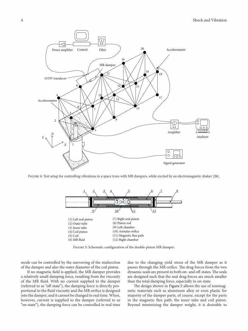
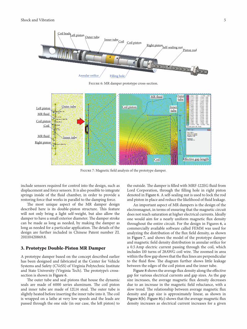
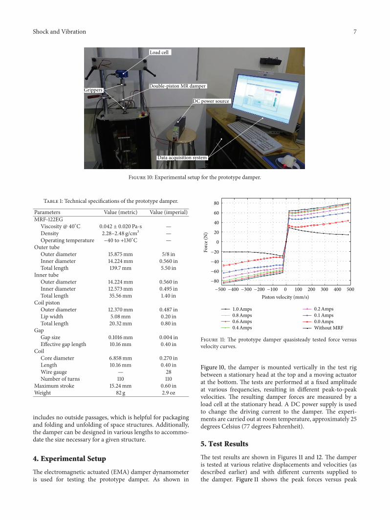
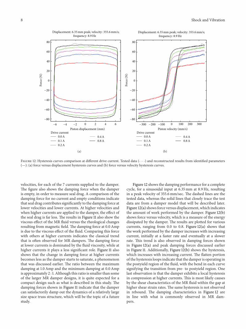
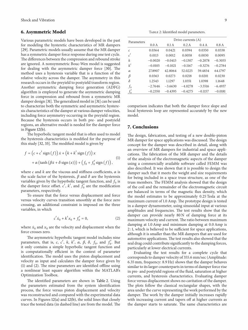

International Journal of
AerospaceEngineeringHindawi Publishing Corporationhttpwwwhindawicom Volume 2014
RoboticsJournal of
Hindawi Publishing Corporationhttpwwwhindawicom Volume 2014
Hindawi Publishing Corporationhttpwwwhindawicom Volume 2014
Active and Passive Electronic Components
Control Scienceand Engineering
Journal of
Hindawi Publishing Corporationhttpwwwhindawicom Volume 2014
International Journal of
RotatingMachinery
Hindawi Publishing Corporationhttpwwwhindawicom Volume 2014
Hindawi Publishing Corporation httpwwwhindawicom
Journal ofEngineeringVolume 2014
Submit your manuscripts athttpwwwhindawicom
VLSI Design
Hindawi Publishing Corporationhttpwwwhindawicom Volume 2014
Hindawi Publishing Corporationhttpwwwhindawicom Volume 2014
Shock and Vibration
Hindawi Publishing Corporationhttpwwwhindawicom Volume 2014
Civil EngineeringAdvances in
Acoustics and VibrationAdvances in
Hindawi Publishing Corporationhttpwwwhindawicom Volume 2014
Hindawi Publishing Corporationhttpwwwhindawicom Volume 2014
Electrical and Computer Engineering
Journal of
Advances inOptoElectronics
Hindawi Publishing Corporation httpwwwhindawicom
Volume 2014
The Scientific World JournalHindawi Publishing Corporation httpwwwhindawicom Volume 2014
SensorsJournal of
Hindawi Publishing Corporationhttpwwwhindawicom Volume 2014
Modelling amp Simulation in EngineeringHindawi Publishing Corporation httpwwwhindawicom Volume 2014
Hindawi Publishing Corporationhttpwwwhindawicom Volume 2014
Chemical EngineeringInternational Journal of Antennas and
Propagation
International Journal of
Hindawi Publishing Corporationhttpwwwhindawicom Volume 2014
Hindawi Publishing Corporationhttpwwwhindawicom Volume 2014
Navigation and Observation
International Journal of
Hindawi Publishing Corporationhttpwwwhindawicom Volume 2014
DistributedSensor Networks
International Journal of