Research Activities in Rock Mechanics/Engineering at …€¦ · UTRE Phase II Research Activities...
43
UTRE Phase II Research Activities in Rock Mechanics/Engineering at CEE/NTU A/P Zhao Zhiye Nanyang Centre for Underground Space (NCUS) School of Civil and Environmental Engineering (CEE) Nanyang Technological University (NTU) 1
Transcript of Research Activities in Rock Mechanics/Engineering at …€¦ · UTRE Phase II Research Activities...

UTRE Phase II
Research Activities in Rock
Mechanics/Engineering at CEE/NTU
A/P Zhao Zhiye
Nanyang Centre for Underground Space (NCUS)
School of Civil and Environmental Engineering (CEE)
Nanyang Technological University (NTU)
1

Presentation Outline
Research areas
• Rock Dynamics and Protection of Underground Structures
• Advanced Numerical Modelling for Rock Cavern Design
• GIS-based Digital Rock Engineering
• Fire Safety, Evacuation, Social/economic studies
Research Projects
• Jurong rock caverns (JTC)
• Shaft design (I3C/NTU)
• NTU underground space exploration (SEO/NCUS)
• Biogrouting (SUL/MND)
2

A/P Low Bak Kong
Rock Mechanics
A/P Zhao Zhiye
Rock Mechanics A/P Yang Yaowen
Instrumentation
Prof Tan Kang Hai
Fire Safety,
Evacuation
A/P Tiong Lee Kong
Risk Modelling
A/P Goh Teck Chee,
Anthony
Rock/Soil Mechanics
Asst/P Wong Ngai Yuen,
Louis
Engineering Geology
Core Members in Rock Engineering, CEE, NTU
Rock Engineering Research Group , CEE, NTU
Prof. Zhao Jian
Advisor to NCUS
Monash Univ, Rock
Mechanics/Eng
Prof. Lu Ming
Director of NTU/JTC I3C
Centre, Rock Eng.
Dr Zhou Yingxin
Senior Principal
Engineer of DSTA
Adjunct A/P of CEE,
Rock Eng
3

Rock Dynamic Testing
• 75 mm diameter pressure bars
• 50 mm diameter pressure bars
• Steel, aluminum, PMMA bars
• Granite pressure bars
• High strength cement bars
• Gas gun
• High speed camera
SHPB Test Facilities in NTU
4

Rock Dynamic Tests
Joints in rock mass Stress wave propagation in rock mass
Low strain rate Medium strain rate High strain rate
5

Development of numerical methods
• 2D discontinuous deformation analysis (DDA)
• 2D/3D numerical manifold method (NMM)
• Reliability based analysis method.
• Rock caverns under blast loads.
• Rock caverns under earthquake loads.
• Rock caverns under coupled fluid/in-situ stress.
6

7
Basic Concept of DDA
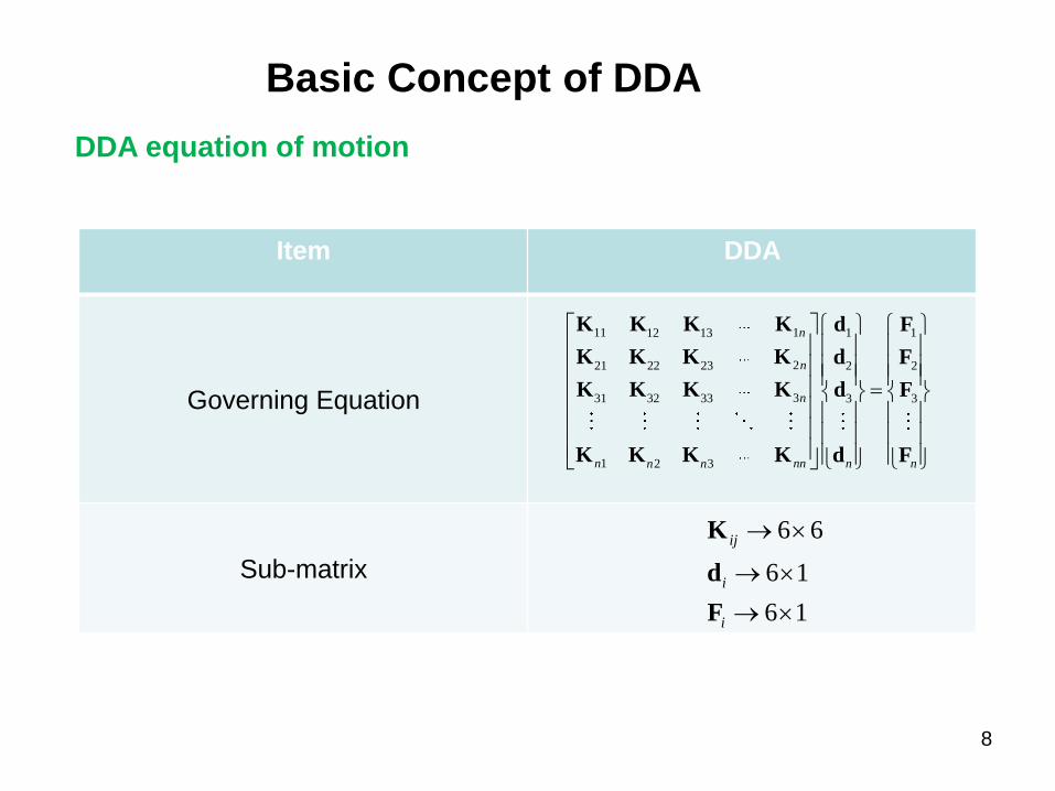
Item DDA
Governing Equation
Sub-matrix
11 1 1 112 13
221 22 23 2 2
331 32 33 3 3
1 2 3
n
n
n
n nn n nn n
K K K K d F
K K K K d F
K K K K d F
K K K K d F
6 6
6 1
6 1
ij
i
i
K
d
F
DDA equation of motion
8
Basic Concept of DDA

Coupling of FEM/DDA – a nodal based DDA (NDDA)
9
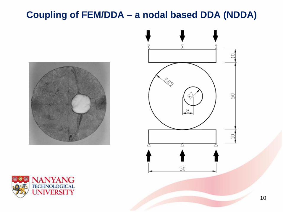
Coupling of FEM/DDA – a nodal based DDA (NDDA)
10

Coupling of FEM/DDA – a nodal based DDA (NDDA)
Analysis Parameters
Rock
sample
Unit mass (kg/m3) 2600
Young’s modulus (GPa) 10
Poisson ratio 0.25
Friction angle 25˚
Cohesion strength (MPa) 25
Tensile strength (MPa) 12
Rigid plate
Unit mass (kg/m3) 7800
Young’s modulus (GPa) 2000
Poisson ratio 0.25
Friction angle 25˚
Cohesion strength (MPa) 2500
Tensile strength (MPa) 2500
Joint/crack
Friction angle 20˚
Cohesion strength (MPa) 0
Tensile strength (MPa) 0
Control
parameter
Penalty stiffness (GN/m) 4000
Time step size (s) 1×10⁻⁵
Max displacement ratio 0.01
SOR factor 1.0
Total analysis time (s) 0.003
11

Probabilistic risk assessment of rock caverns
Charts relating limit state safety factor to cavern characteristics
12

2D/3D manifold method modelling for jointed rock mass
Slope analysis with 3D NMM
13
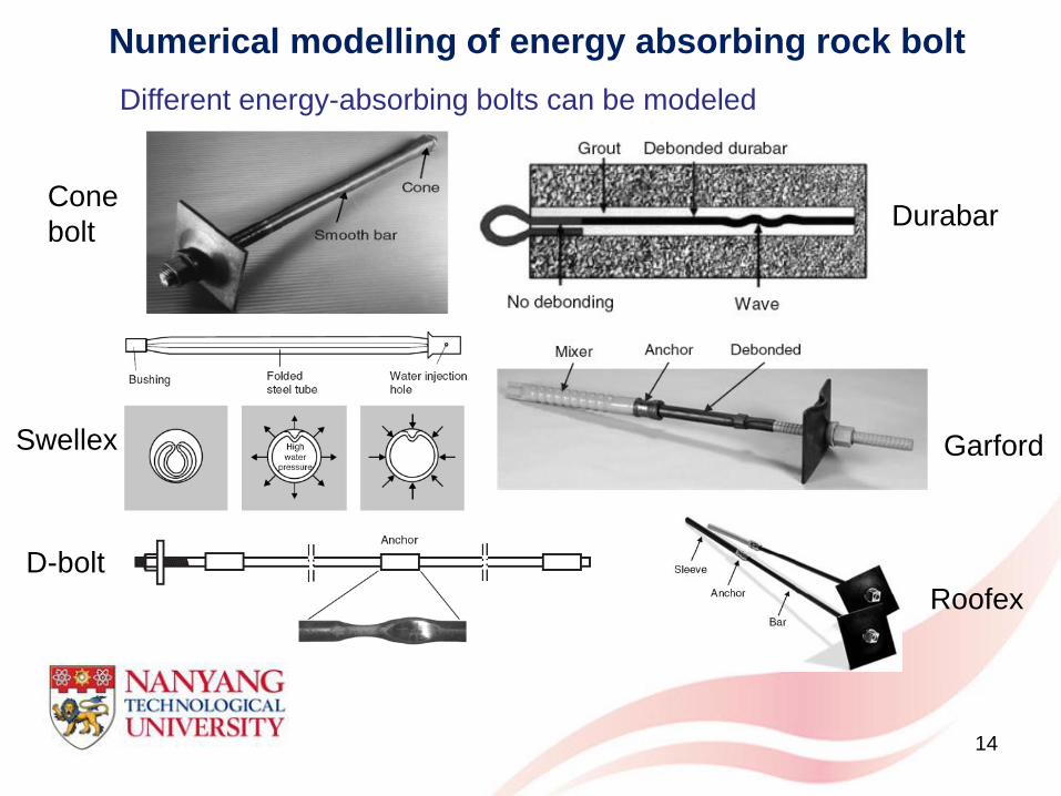
Numerical modelling of energy absorbing rock bolt
Different energy-absorbing bolts can be modeled
Cone
bolt Durabar
Swellex Garford
Roofex
D-bolt
14

Performance comparison of energy-absorbing rockbolts
0.0 0.2 0.4 0.6 0.8 1.0 1.2 1.4 1.60
5
10
15
20
25
30
Ax
ial
ten
sile
lo
ad (
kN
)
Distance away from the far end of the bolt (m)
0.0 0.2 0.4 0.6 0.8 1.0 1.2 1.4 1.60
5
10
15
20
25
30
Ax
ial
ten
sile
lo
ad (
kN
)
Distance away from the far end of the bolt (m)
Rebar (fully grouted) D-bolt
15

UTRE Phase II
3D NMM modelling
16
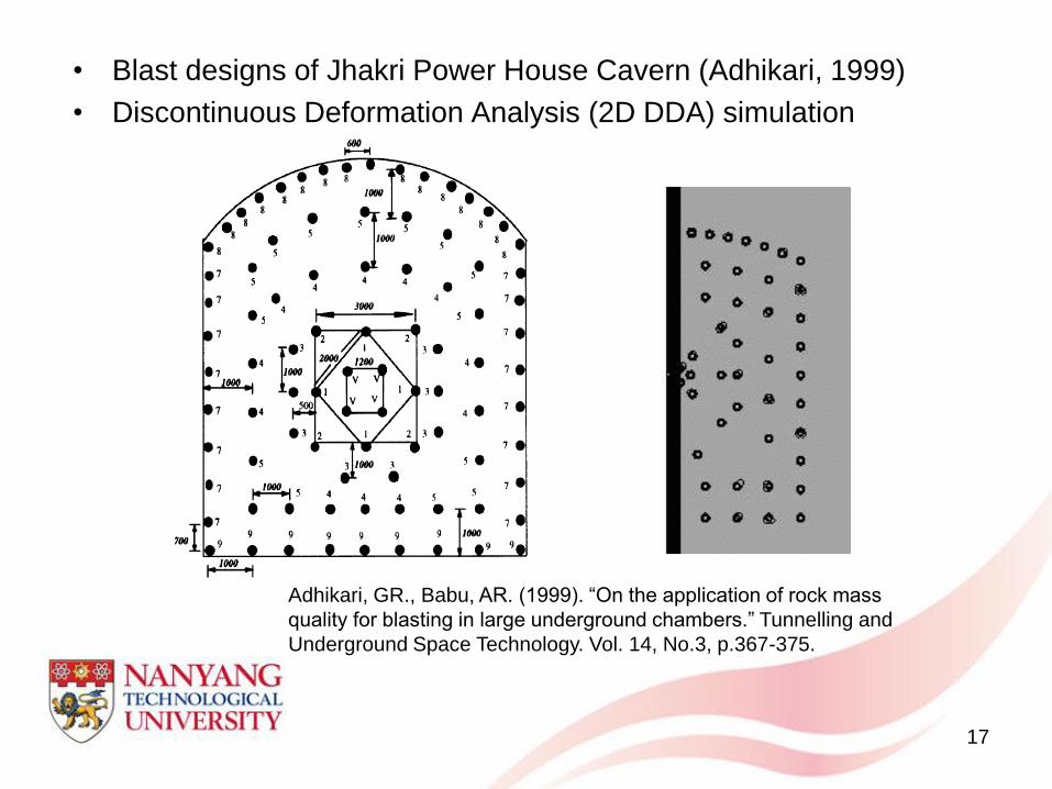
UTRE Phase II • Blast designs of Jhakri Power House Cavern (Adhikari, 1999)
• Discontinuous Deformation Analysis (2D DDA) simulation
Adhikari, GR., Babu, AR. (1999). “On the application of rock mass
quality for blasting in large underground chambers.” Tunnelling and
Underground Space Technology. Vol. 14, No.3, p.367-375.
17

Rock Dynamic Modelling
Development of Key block theory, discontinuous deformation analysis
(DDA), numerical manifold method (NMM)
18

Instrumentations and Monitoring
Fibre optic
sensor (FBG)
Piezoceramic
(PZT) sensor
FOS Spectrum Analyzer
PZT Impedance Analyzer
Cycle IV
0
20
40
60
80
100
120
140
0 500 1000 1500 2000
Microstrain
Str
ess (
MP
a)
ESG(60mm)
FBG
0.00035
0.0004
0.00045
0.0005
0.00055
60 70 80 90 100
Frequency (kHz)
Conducta
nce (
S)
Load ratio= 0 Load ratio= 0.33
Load ratio= 0.66 Load ratio= 0.82
Global information
(strain, displacement, etc)
Local information
(damage location
and severity)
19

3D GIS for Subsurface Application
Multi-Layered Surfaces and Cavern
Subsurface Geological Modelling and Analysis
20

Borehole Information System
21

Fire Safety Modelling
XZ
Y
g
Window
Compartment
HRRHeat Transfer
Mass Transfer
XZ
Y
gg
Window
Compartment
HRRHeat Transfer
Mass Transfer
Zone model
Evacuation modeling
• Human behavior
•Tenability condition
22

Social, Economic and Environmental Impacts on Use
of Underground Space
• Environmental Impact Analysis (EIA)
• Social and Economic Impacts • Risk Modelling, DAT system (MIT)
23

UTRE Phase II Jurong Rock Caverns Project - Basic Facts (Phase 1)
o Built beneath the seabed of Banyan Basin (~120 m).
o Storage capacity of approximately 1.47 million cubic meters
o To store liquid hydrocarbons such as crude oil, condensate and naphtha.
o Save approximately 60 hectares of surface land space.
24

UTRE Phase II
25
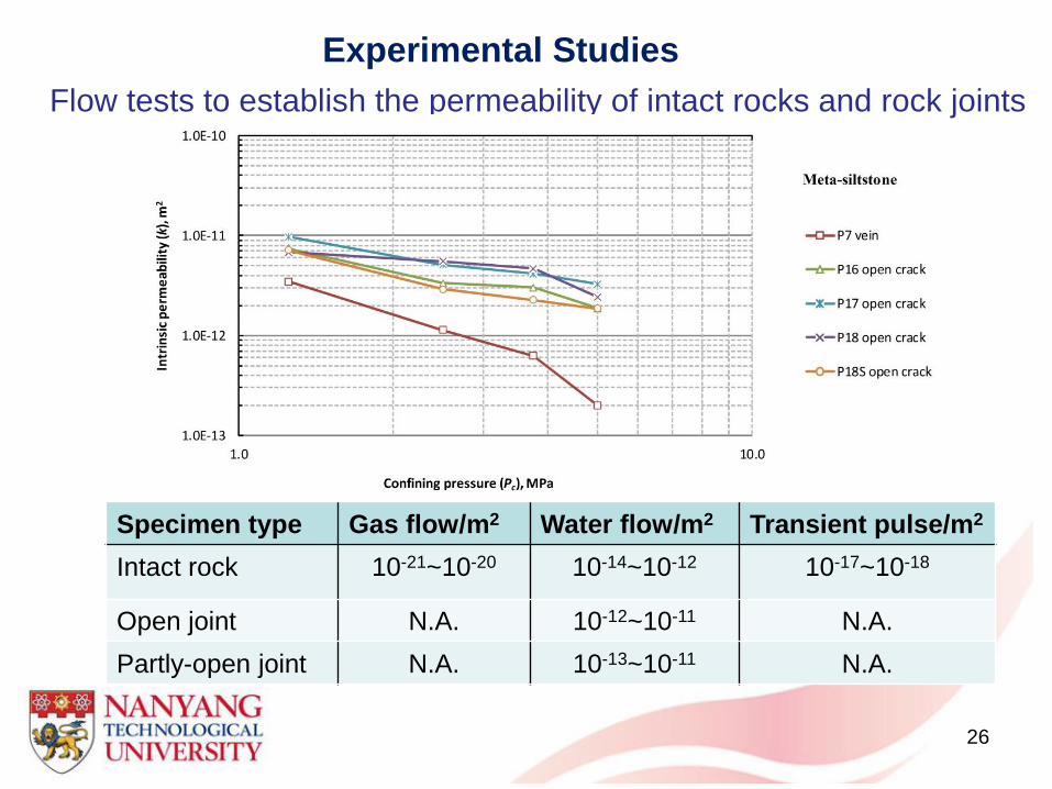
Experimental Studies
Flow tests to establish the permeability of intact rocks and rock joints
Specimen type Gas flow/m2 Water flow/m2 Transient pulse/m2
Intact rock 10-21~10-20 10-14~10-12 10-17~10-18
Open joint N.A. 10-12~10-11 N.A.
Partly-open joint N.A. 10-13~10-11 N.A.
26

Schematic of Tunnel Trial Test
Sensor Installation : Before and after shotcreting
in tunnel
Estimated displacements at sensor locations
Total station and FOS displacement at crown of tunnel
Tunnel test: Testing the survivability of the customized FOSs against
shotcreting, and drill-and-blast impact.
Potential instrumentation plan for cavern
monitoring
Instrumentation
27

Predicted 3D hydraulic conductivities
Water inflow comparison
(predicted VS measured)
Rock Caverns Seepage Analysis
28

2D 3D
29
140m wide ,425m long and 165m deep

Numerical Analysis:
Excavation sequence
with UDEC
30

Numerical analysis of underground rock excavations
with FLAC3D, UDEC, 3DEC, Rocscience.
Response surface method as a link between
reliability methods and stand-alone numerical
packages, and second-order reliability method.
Probabilistic Analysis of Underground Rock Excavations
accounting for Uncertainty
31

32
Elliptical
Circular Rectangle
Multi-cell
Optimization of vertical access shaft for underground space
32
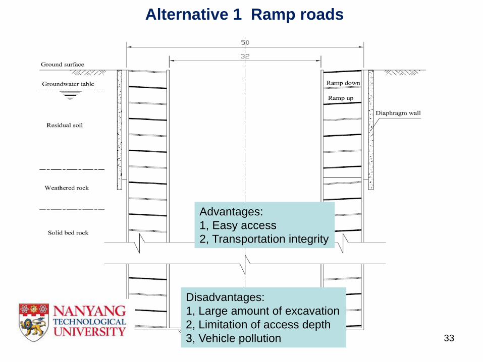
Disadvantages:
1, Large amount of excavation
2, Limitation of access depth
3, Vehicle pollution
Advantages:
1, Easy access
2, Transportation integrity
Alternative 1 Ramp roads
33

Disadvantages:
1, Add works of tunnel excavation
2, Limitation of access depth
3, Vehicle pollution
Advantages:
1, Easy access
2, Transportation integrity
3, Reduce amount of excavation
compare with Alt 1
Alternative 2 Ramp roads plus spiral tunnel
34

Alternative 3 Ramp roads plus lift
Advantages:
1, Least amount of excavation
2, No limitation of access depth
3, Using conveyor belt to muck
4, Car lift for cargo and small
lift for person during operation
Disadvantages:
Lack of transportation integrity
35

BACKGROUND
Utilizing the space in NTU campus in response to the need of its expansion
UNDERGROUND SPACE below NTU Campus – A
Concept Master Planning
36

37
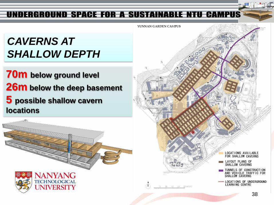
CAVERNS AT
SHALLOW DEPTH
70m below ground level
26m below the deep basement
5 possible shallow cavern
locations
38

DEEP CAVERNS
120m below ground level
26m below the shallow cavern
76m from the deep basement
6 possible shallow cavern locations
39

Biogrouting for
underground construction
Objectives
• To develop a new grouting material – biogrout and
use it to establish a new construction approach –
biogrouting before excavation – to seal the joints and
strengthen the weak rock in the areas where caverns or
tunnels are to be constructed before excavation.
40

Sand grain
Slime bonding
Sand grain
Sand grain
Slime bonding
Sand grain
Scanning Electron Micrograph
(SEM) showing the formation
of Crystals of CaCO3
Bonding of sand
grains by slime
How does it work?
A grouting material made of good microorganisms and other waste
41

Application potential
• The project is motivated to solve real construction problems. It
can be used directly into existing projects using existing
grouting systems once biogrout is invented and the related
technologies are fully developed.
Biogrout
Biogrout
Use biogrout for rock joints or concrete repair
42

Acknowledgements
• Some of the slides in this presentation are provided by my
colleagues in CEE/NTU, including Tan KH, Low BK, Anthony
Goh, Louis Wong, Lu Ming, Yang YW, Robert Tiong, Chu Jian,
Tan SK, and their researchers.
• local/overseas collaborators in the various projects.
• Financial support from JTC, DSTA, SEO/NCUS (NTU),
I3C(JTC/NTU)
43