Rescue Robot League –3rd Place Award Winner IUTMicrobot,...
11
Rescue Robot League –3 rd Place Award Winner IUTMicrobot, Iran Hamid Mir Mohammad Sadeghi 1 , Hamed Bastani 2 and Ehsan Azarnasab 2 1 Electrical and Computer Eng. Research Center, General Director, ECERC of Isfahan Uni- versity of Technology, Isfahan , Iran, 84156 [email protected] http://www.ecerc.org 2 Student of Electrical Control Eng. In IUT and part time researcher in ECERC, ECERC of Isfahan University of Technology, Isfahan, Iran, 84156 {Hamed, Ehsan} @ ecerc.org http://www.ecerc.org/iutmicrobot Abstract. IUTMicrobot has focused its researches on Rescue Robots chiefly for 2 years. The goal was implementing robots, to make search and rescue ac- tion easier and safer in realistic condition. The idea was implementing two ro- bots, one fast and small; the latter to get a global view of disaster and prepare a path sketch, the former slow but with complete set of equipments; to get vic- tims and environment details. NIST test bed provided in RobocupRescue2003 was a good opportunity to test robots in semi-realistic settings. The ability of our Robots in remotely detecting victims, using non-touch accurate sensors, perfect & user friendly interface, and generating map outside the disaster arena, are main advantages for successful search and rescue actions. Different parts of Robots; sensors, hardware & software, are presented in this paper. Then the Robot control scheme, mapping method, and user interface are introduced. Also, this paper addresses mobile robot localization in urban environment. 1 Introduction There is nothing as beautiful as creating. A creature can see, hear, talk, write, move, think, and decide. A Robot! IUTMicrobot team was formed in 1999. The major activities are in Robotics field. It is affiliated by ECERC (Electrical & Computer Engineering Research Center) of IUT (Isfahan University of Technology). It was our first experience participating in Robocup Rescue, and we got 3 rd place in Rescue Robot League Competition. This has not been the only award during our robotics activities, we got 1 st place in RoboDeminer Contest 2002 which was held by United Nations with the goal of "Looking for peace and safety”, and 2 nd place in IntelligentMice Robot Contest 2001, Iran. We participated in RoboCupRescue 2003, Padova, Italy, with two Robots work- ing cooperatively. One called ECERC1 (Fig.4) which is equipped with needed
Transcript of Rescue Robot League –3rd Place Award Winner IUTMicrobot,...

Rescue Robot League –3rd Place Award Winner IUTMicrobot, Iran
Hamid Mir Mohammad Sadeghi1, Hamed Bastani2 and Ehsan Azarnasab2
1 Electrical and Computer Eng. Research Center, General Director, ECERC of Isfahan Uni-versity of Technology, Isfahan , Iran, 84156
[email protected] http://www.ecerc.org
2 Student of Electrical Control Eng. In IUT and part time researcher in ECERC, ECERC of Isfahan University of Technology, Isfahan, Iran, 84156
{Hamed, Ehsan} @ ecerc.org http://www.ecerc.org/iutmicrobot
Abstract. IUTMicrobot has focused its researches on Rescue Robots chiefly for 2 years. The goal was implementing robots, to make search and rescue ac-tion easier and safer in realistic condition. The idea was implementing two ro-bots, one fast and small; the latter to get a global view of disaster and prepare a path sketch, the former slow but with complete set of equipments; to get vic-tims and environment details. NIST test bed provided in RobocupRescue2003 was a good opportunity to test robots in semi-realistic settings. The ability of our Robots in remotely detecting victims, using non-touch accurate sensors, perfect & user friendly interface, and generating map outside the disaster arena, are main advantages for successful search and rescue actions. Different parts of Robots; sensors, hardware & software, are presented in this paper. Then the Robot control scheme, mapping method, and user interface are introduced. Also, this paper addresses mobile robot localization in urban environment.
1 Introduction
There is nothing as beautiful as creating. A creature can see, hear, talk, write, move, think, and decide. A Robot!
IUTMicrobot team was formed in 1999. The major activities are in Robotics field. It is affiliated by ECERC (Electrical & Computer Engineering Research Center) of IUT (Isfahan University of Technology). It was our first experience participating in Robocup Rescue, and we got 3rd place in Rescue Robot League Competition. This has not been the only award during our robotics activities, we got 1st place in RoboDeminer Contest 2002 which was held by United Nations with the goal of "Looking for peace and safety”, and 2nd place in IntelligentMice Robot Contest 2001, Iran. We participated in RoboCupRescue 2003, Padova, Italy, with two Robots work-ing cooperatively. One called ECERC1 (Fig.4) which is equipped with needed

Fig. 1. ECERC1 Aspect Ratio
Sensors to detect and locate victims using their vital signs and chemical characteris-tics (see Sect. 4).
The second Robot called ECERC2 (Fig.5) is smaller and faster. It is used to get a global view of disaster and prepare a path sketch and is merely equipped with a wire-less color pan camera. Fig.2 shows the general block diagram of Robots and Operator Station.
ECERC1 has a Pan/Tilt (2 DoF) Set (PTS) on it, as Victims Identification Sensors Unit (VISU). It consists of a none-touch infrared thermometer, wireless color pin-hold video camera, ultra sonic range-finder, AGC microphone and speaker, and laser-pointer. There are some sensors to read situation of PTS (Angles) for feedback. PTS can change it’s situation in spherical coordination ((r,θ,ϕ) while r = cte related to Robot), and centralize on victim remotely, without touching . Based on coordination related to start-point of arena (x0, y0, z0) in Cartesian system, operator station proces-sor (PCU) can calculate the remote-victim’s location and status. PCU in both Robot and operator side is a laptop.
Additionally, a Smoke-Detector and a CH4 sensor are provided on robot (not used in NIST test bed, Robocup Rescue 2003).
Fig. 2. Robot and Operator Station Block Diagrams

Navigation Unit (RNU) of ECERC1 uses a front webcam for a straight vision, an analog wireless color video camera (on PTS), and also an Omni directional digital camera (for a global view of arena).
The ECERC1 communicates with operator station using a 2.4 GHz WLAN for data, and 1.2 GHz for video.
Fig.3 represents ECERC1’s data acquisition flow graph. ECERC2 uses a pan wireless color video camera as RNU, VISU and RLU (Local-
ization Unit). It communicates on 56 MHz for data and 1.2GHz for video. Operator side’s PCU uses on-line video and received data, then prepares them for
controlling, monitoring, saving and printing. Operator can remotely check either Robot’s behavior or correct any mistakes, to accomplish the search action. Finally he/she can edit the computer-generated map and send it to a printer.
In Rescue settings, issues such as operator fatigue, lack of situational awareness of the operator, cognitive load on the operator, and the number of individuals an opera-tor can control in real time, all place limitations on human control [1]. To decrease these limitations, not only an autonomous Robot with complicated AI core is needed, but also an operator is inevitable for critical decisions.
We plan to improve our system autonomy for next year.
Fig. 3. Data Acquisition Block Diagram
2 Robot Locomotion
ECERC1 is a 4WD system with 2 freely moving wheels totally 6 wheels (Fig.1) and ECERC2 moves by independently driven side caterpillars, like a Tank. So, both Ro-bots have Differential-Drive architecture for motion. This method harnesses both Linear and Rotational velocities [2].

Robot PCU decodes and translates received commands through Robot Communi-cation Unit (RCU), then transfers them to Locomotion & Drive Unit (LDU). ECERC1 employs 4x12W DC motors for movement. The main part of motor drive circuit is L298 IC. Wheels are connected to motors through appropriate gear-boxes. For kicking motor spikes back, RC filters are used. This method protects communica-tion instruments and processor unit against motor noise [8]. PTS also uses two low-power DC motors.
Fig. 4. ECERC1
3 Navigation and Localization
It is important to localize Robot related to a set point in arena, absolutely (while vic-tim’s position is relative to robot’s coordination).
Operator navigates ECERC1 using an omni-directional digital camera, and ECERC2 by its rotary camera. A GPS is provided for automatic localization [9] of ECERC1. So that the software sets start point as a reference point for mapping and tracking. But we couldn’t use GPS to localize and navigate the Robot; because of no satellite coverage in the test arenas in Robocup, 2003 NIST test bed. In a real col-lapsed building, there may not be enough signal for a GPS, to localize itself. So, GPS is not a good solution for localization in real-rescue and operator have to localize the Robot(s) visually, it also reduces overall performance and waists rescue-time. How-ever, we should solve the localization problem using other odometery methods for future.

4 Victim Identification Sensors
According to NIST standards for simulated victims [3], the Robot should detect vic-tims by their vital signs. ECERC1 can measure victims’ temperature using a Non-Touch Infra-Red Thermometer. It also checks audible signals using an AGC micro-phone and sends them to operator station. Motion and body form of a victim is de-tected visually, while a laser points victim in video image. The distance between
Fig. 5. ECERC2
Robot and victim (r) is measured using an ultrasonic transceiver as a telemetric set. All these sensors are provided on PTS. Robot can whirl PTS to focus on a far-victim (Fig.7). Sensors’ outputs are normalized, coded, and packaged in a frame through interface circuits and microcontroller, preparing a packet to be sent to operator sta-tion, while classified headers and trailers are added for more security and safety. Online map generation (including victim’s status and situation) is upon received raw packets. So, if the robot goes out of work, operator knows last Robot position and found victims.
5 Mapping the Environment
To have flexibility and reliability, mapping process is done in operator side and the map is saved automatically. As Robot moves, GPS output (RS232) changes. PCU compares current latitude and longitude with (E0, N0) as zero point, so, Robot location (RX, RY) is calculated, then Robot footprint is produced by connecting them (black lines in Fig.6). Smoothing the path (red lines in Fig.6) extracts a better approximation for Robot direction (N).
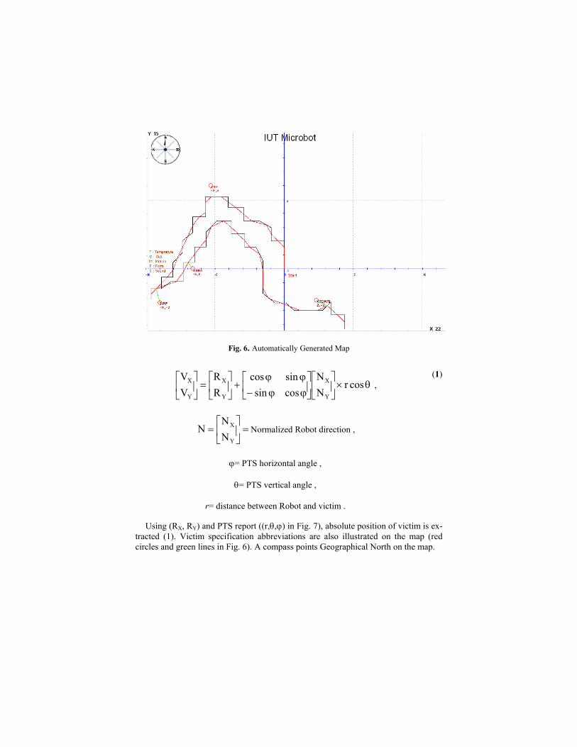
Fig. 6. Automatically Generated Map
θ×
ϕϕ−ϕϕ
+
=
cosr
NN
cossinsincos
RR
VV
Y
X
Y
X
Y
X ,
=
=
Y
X
NN
N Normalized Robot direction ,
ϕ= PTS horizontal angle ,
θ= PTS vertical angle ,
r= distance between Robot and victim .
(1)
Using (RX, RY) and PTS report ((r,θ,ϕ) in Fig. 7), absolute position of victim is ex-tracted (1). Victim specification abbreviations are also illustrated on the map (red circles and green lines in Fig. 6). A compass points Geographical North on the map.

Fig. 7. Trigonometrical Vectors
6 Control Scheme
Acquired data of arena and victims, are sent to operator side PCU. It checks them, localizes Robot, calculates victims’ situation, tracks the Robot and finally generates the map. Operator can check either video sent by Robot or GUI outputs. He/She can correct the path, map and even drive Robot manually. So, ECERC1 is partially autonomous, while ECERC2 is tele-operated, i.e. a human being closes the general control loop.
ECERC1’s actions (especially moving in disaster building), are comprehensively based on received commands from operator station. If RCU is disconnected from station (e.g. by radio interference), or when operator station PCU halts, it opens con-trol loop and makes Robot unruly being menace for arena and Victims both. Also, hanging Robot’s PCU may be hazardous for environment, victims, even the Robot itself. So, a local controller is provided on the Robot. It checks Robot’s behavior, data flow, and local feedbacks (DC motors of Robot, Left & Right optical hard limits (OHL) of PTS, etc.). When RCU or PCU output is invalid, it disables all motion instruments on Robot. It is composed of 8255WD (with embedded watch dog), PAL, and some momentary elements. It is considered in Robot-model and prepares a gentle action. Fig.8 shows the close loop control flow graph.
Fig. 8. Control Loop

Fig. 9. GUI
7 Operator Station
Laptop’s mouse, keyboard, monitor, headset and an additional TV are ECERC1’s operator station parts. Detailed operator station flow graph is shown in Fig. 10.
Operator uses Graphical User Interface (GUI) for monitoring the Robot and disas-ter area to control the Robot, finding victims and their status and proceeding rescue actions. GUI interacts in scientific international language, English.
Temperature and audio interface helps the operator to find hidden victims. GUI and PCU software are implemented by Microsoft visual basic 6.0 and other available ActiveXes, considering HMI standards [4].
RLU, VISU, RNU and PTS outputs build a user friendly virtual panel on GUI (Fig.9). External control commands are framed and sent to Robot by communication unit (CU). To keep the communication channel alive, Frame Generator creates “keep alive” command, when the channel is free. Operator can restart Robot control board, remotely.

Fig. 10. Operator Station Flow Graph
8 Communication
ECERC1 communicates with operator station, outside the test arena or real disaster area, sending information and receiving commands. So, a local P2P connection is implemented by PCMCI WLAN cards. It is compatible with IEEE 802.11 standards [10]. Digital videos (webcams’ outputs) and audible signals are sent over UDP, while TCP is used for data/commands [5]. Analog video is transmitted by means of a video sender on 1.2 GHz.
ECERC2 communicates on 56 MHz for both data and commands, and sends video on 1.2 GHz.
9 Performance Observations
We believe our user interface is perfect and includes adequate properties to control and monitor the Robot. Robot’s sensors for finding victims play their role well, while implemented PTS, improves Robot flexibility and helps the Robot to distinct victims, remotely. Also using PCU-independent local-controller provided on Robot, made it safe for real rescue action. Another benefit is that; just one operator can check, con-trol and monitor more than one Robot. ECERC1 and ECERC2 work cooperatively, i.e. they can help and complement each other in rescue operation. Generating map outside the rescue arena would help the human-rescuers if the Robot system crashed. Our team setup and breakdown time was proper, because of packaging equipments; which is essential for real rescue. Finally language independent GUI considering HMI standards is another merit.
10 Future Directions
For a realistic use of Robots in search and rescue, we plan to improve mechanical structure of our Robot(s); to be more powerful and stable, complete sensor-set and make the Robot(s) closer to a full autonomous system. Localizing and navigating methods will excel.
11 Acknowledgement
Thanks those who provided support for our research efforts in Isfahan university of Technology (IUT), especially Electrical & Computer engineering Research Center (ECERC).
References
1. Casper, J., Murphy, R.: 2002 Workflow on human-robot interaction in USAR, in proceed-ings of the IEEE international conference on Robotics and Automation, volume 2, 1997-2003. Washington, DC: IEEE (2002)
2. Davarpanah-Jazi, M., Bastani, H., Azarnasab, E., Shariatmadari, A.: IUTMicrobot RoboDeminer2002 paper, proceedings of the 2002 International RoboDeminer Contest Workshop, in association with United Nations, Tehran, Iran (2002)
3. Jacoff, A., Messina, E., Evans, J.: Experience in Deploying Test Arenas for Autonomous Mobile Robots, Intelligent Systems Division, National Institute of Standards and Technol-ogy, Mexico (2001)
4. Human Machine Interface Standards, Department of Energy Multi laboratory Project (2003) 5. Naugle, M.G.: Illustrated TCP/IP, (Book Style). John Wiley & Sons (1998) 6. Wilson, E., Rock, S.M.: Reconfigurable Control of a Free-Flying Space Robot Using Neural
Network, American Control Conference, Seattle, Washington (1995)

7. Mir Mohammad Sadeghi, H., Bastani, H., Azarnasab, E.: IUTMicrobot Robocup 2003 TDP, Proceedings of the International Robocup 2003, Padova, Italy (2003)
8. Bastani, H.: Motor drivers architecture, circuits and filtering, ECERC internal technical report (2002)
9. Hada, H., Uehara, K., Sunahara, H., Murai, J. , Petrovski, I., Torimoto, H. , Kawaguchi, S.: Differential and RTK corrections for the internet car using GPS, Nara Institute of Science and Technology & DX Antenna Co. Ltd, Japan .
10. Chayat, N.: Frequency hopping spread spectrum PHY of the IEEE 802.11 wireless LAN standard, doc.: IEEEp802.11-96/49D, BreezeCom (1996)