Requirements Engineering and the Semantic Web: Part II ...
79
ISR Technical Report Requirements Engineering and the Semantic Web: Part II. Representation, Management, and Validation of Requirements and System-Level Architectures By Vimal Mayank 1 , Natalya Kositsyna 2 and Mark Austin 3 Last updated : February 12, 2004. 1 Graduate Research Assistant, Master of Science in Systems Engineering (MSSE) Program, Institute for Systems Research, University of Maryland, College Park, MD 20742, USA. 2 Faculty Research Assistant, Institute for Systems Research, College Park, MD 20742, USA. 3 Associate Professor, Department of Civil and Environmental Engineering, and Institute for Systems Research, University of Maryland, College Park, MD 20742, USA. 0
Transcript of Requirements Engineering and the Semantic Web: Part II ...

ISR Technical Report
Requirements Engineering
and the Semantic Web: Part II.
Representation, Management, and Validation of
Requirements and System-Level Architectures
By Vimal Mayank1, Natalya Kositsyna2 and Mark Austin3
Last updated : February 12, 2004.
1Graduate Research Assistant, Master of Science in Systems Engineering (MSSE) Program, Institute for Systems Research, University ofMaryland, College Park, MD 20742, USA.
2Faculty Research Assistant, Institute for Systems Research, College Park, MD 20742, USA.3Associate Professor, Department of Civil and Environmental Engineering, and Institute for Systems Research, University of Maryland,
College Park, MD 20742, USA.
0

Contents
1 Introduction 11.1 Problem Statement . . . . . . . . . . . . . . . . . . . . . . . . . . . . . . . .. . . . . . . . . . 11.2 Scope and Objectives . . . . . . . . . . . . . . . . . . . . . . . . . . . . . .. . . . . . . . . . . 51.3 The Semantic Web . . . . . . . . . . . . . . . . . . . . . . . . . . . . . . . . . .. . . . . . . . 7
1.3.1 Technologies in the Semantic Web Layer Cake . . . . . . . . .. . . . . . . . . . . . . . 71.3.2 The URI and Unicode Layer . . . . . . . . . . . . . . . . . . . . . . . . .. . . . . . . . 71.3.3 The eXtensible Markup Language (XML) Layer . . . . . . . . .. . . . . . . . . . . . . 71.3.4 The Resource Description Framework (RDF) Layer . . . . .. . . . . . . . . . . . . . . . 91.3.5 Ontologies . . . . . . . . . . . . . . . . . . . . . . . . . . . . . . . . . . . .. . . . . . 111.3.6 Logic (and Rules) . . . . . . . . . . . . . . . . . . . . . . . . . . . . . . .. . . . . . . . 131.3.7 Digital Signatures . . . . . . . . . . . . . . . . . . . . . . . . . . . . .. . . . . . . . . 131.3.8 Proof, Trust, and Beyond . . . . . . . . . . . . . . . . . . . . . . . . .. . . . . . . . . . 13
1.4 Organization of this Report . . . . . . . . . . . . . . . . . . . . . . . .. . . . . . . . . . . . . . 141.5 Acknowledgments . . . . . . . . . . . . . . . . . . . . . . . . . . . . . . . . .. . . . . . . . . 15
2 Representation and Management of Requirements 162.1 Organization of Requirements . . . . . . . . . . . . . . . . . . . . . .. . . . . . . . . . . . . . 162.2 Requirements Allocation and Flowdown . . . . . . . . . . . . . . .. . . . . . . . . . . . . . . . 162.3 Graph Representation of Requirements . . . . . . . . . . . . . . .. . . . . . . . . . . . . . . . . 172.4 Requirement Template Structure . . . . . . . . . . . . . . . . . . . .. . . . . . . . . . . . . . . 192.5 XML and RDF Representation of Requirements . . . . . . . . . . .. . . . . . . . . . . . . . . . 202.6 Requirement Traceability and Controlled Visualization . . . . . . . . . . . . . . . . . . . . . . . 222.7 RDQL Approach to Retrieve Nodes and Links . . . . . . . . . . . . .. . . . . . . . . . . . . . . 24
3 Synthesis of System-Level Architectures from Reusable Component-Specifications 263.1 Component- and Interface-Based Design . . . . . . . . . . . . . .. . . . . . . . . . . . . . . . . 283.2 Libraries of Reusable Component-Specifications . . . . . .. . . . . . . . . . . . . . . . . . . . 293.3 RDF-Based Storage of Object Connectivity . . . . . . . . . . . .. . . . . . . . . . . . . . . . . 293.4 Leaf Requirements Validation Against the Component-Specification . . . . . . . . . . . . . . . . 31
4 Development of a Home Theater System 334.1 Problem Statement . . . . . . . . . . . . . . . . . . . . . . . . . . . . . . . .. . . . . . . . . . 334.2 System Structure . . . . . . . . . . . . . . . . . . . . . . . . . . . . . . . . .. . . . . . . . . . 334.3 System Requirements . . . . . . . . . . . . . . . . . . . . . . . . . . . . . .. . . . . . . . . . . 354.4 Requirement Template Structure . . . . . . . . . . . . . . . . . . . .. . . . . . . . . . . . . . . 364.5 Requirements Traceability and Controlled Visualization . . . . . . . . . . . . . . . . . . . . . . . 394.6 Merging Two Requirement Trees . . . . . . . . . . . . . . . . . . . . . .. . . . . . . . . . . . . 404.7 Collapsing Requirement Tree with Duplications . . . . . . .. . . . . . . . . . . . . . . . . . . . 404.8 Components Library . . . . . . . . . . . . . . . . . . . . . . . . . . . . . . .. . . . . . . . . . 404.9 Low-Level Validation of Requirements . . . . . . . . . . . . . . .. . . . . . . . . . . . . . . . . 42
1

5 Ontology-Enabled Validation of System Architectures 455.1 Model Checking Procedure . . . . . . . . . . . . . . . . . . . . . . . . . .. . . . . . . . . . . . 475.2 Class Relationships in Port-Jack Ontology . . . . . . . . . . .. . . . . . . . . . . . . . . . . . . 475.3 Equivalent DAML Representation of the Ontology . . . . . . .. . . . . . . . . . . . . . . . . . 485.4 Conversion of DAML Representation to Jess Facts . . . . . . .. . . . . . . . . . . . . . . . . . 505.5 Addition of Rules and Execution of Rete Algorithm . . . . . .. . . . . . . . . . . . . . . . . . . 52
6 Conclusions and Future Work 546.1 Conclusions . . . . . . . . . . . . . . . . . . . . . . . . . . . . . . . . . . . . .. . . . . . . . . 546.2 Future Work . . . . . . . . . . . . . . . . . . . . . . . . . . . . . . . . . . . . . .. . . . . . . . 54
Appendices 61Appendix A. XML Representation of the Home Theater System . . . . . . . . . . . .. . . . . . . . . 61Appendix B. RDF Representation of the Requirements Structure . . . . . . . .. . . . . . . . . . . . 64Appendix C. Requirements Property XML File . . . . . . . . . . . . . . . . . . . . . . . .. . . . . . 66Appendix D. DAML Representation of the Cable-Port Ontology . . . . . . . . . .. . . . . . . . . . . 69Appendix E. Jess Assertions and the Rules for the Cable-Port Ontology . .. . . . . . . . . . . . . . . 70
2

Chapter 1
Introduction
1.1 Problem Statement
Modern-day system designs are undergoing a series of radical transformations to meet performance,
quality, and cost constraints. To keep the complexity of technical concerns in check, system-level design method-
ologies are striving to orthogonalize concerns (i.e., achieve separation of various aspects of design to allow more
efficient exploration of the space of potential design alternatives), improve economics through reuse at all levels of
abstraction, and employ formal design representations that enable early detection of errors and multi-disciplinary
design rule checking. Whereas engineering systems have been traditionally viewed in terms of the operations they
support, nowadays there is also a rapidly evolving trend toward to team-development of large-scale information-
dominated systems. These so-called Information-Centric engineering systems exploit commercial-off-the-shelf
(COTs) components, communications technology, and have superior performance and reliability.
Methodologies for Team-Enabled Systems Engineering.A methodology is simply the implementation of a
specific process. As indicated in Figure 1.1, methodologiesfor the team development of system-level architectures
need to support the following activities:
1. Partitioning the design problem into several levels of abstraction and viewpoints suitable for concurrent devel-
opment by design teams. These teams may be geographically dispersed and mobile.
2. Coordinated communication among design teams.
3. Integration of the design team efforts into a working system.
4. Evaluation mechanisms that provide a designer with a critical feedback on the feasibility of system architecture,
and make suggestions for design concept enhancement.
Throughout the development process, teams need to maintaina shared view of the project objectives, and at the
same time, focus on specific tasks. It is the responsibility of the systems engineer to gather and integrate subsystems
and to ensure ensure that every project engineer is working from a consistent set of project assumptions. This
requires an awareness of the set of interfaces and facilities the system will be exposed to.
Systems engineering methodologies are also the confluence of top-down and bottom-up approaches to
system development. Top-down development (decomposition) is concerned with the elicitation of requirements
1

Team 1 Team 2 Team N
ProblemDesign
Working System
AbstractionsViewpoints
team efforts.....Systems integration of
Separation of concernsfor team development.Coordination of activities.
Validation and Verification
Figure 1.1: Key concerns in team development of systems (Source: Discussion with David Everett, NASA God-dard)
and the generation of system architectures – this pathway isshown along the left-hand side of Figure 1.2. Bottom-
up design (composition), in contrast, starts with low-level modules and subsystems and tries to combine them
into higher-level entities. At this stage of development a key design decision is: should we custom build new
components or buy/reuse them? The benefits of reuse include reduced development costs, improved quality (be-
cause components have already been tested), and shortened time-to-market. This so-called “systems integration”
problem has become key and perhaps the most profitable engineering practice.
Over time engineers have learned that in order for the development of systems of ever-increasing size and
complexity to remain tractable, methodologies need to be adjusted so that problems can be formulated in a formal
way, but at higher levels of abstraction. In software engineering circles, the pathway from low-level machine lan-
guages to high-level programming languages is well known. In systems engineering circles, the Unified Modeling
Language (UML) [54] now plays a central role in object-oriented systems development procedures. High-level
visual modeling languages, such as UML, have features whosepurpose is to help an engineer organize thoughts
and ideas on the basic building blocks of the systems design.Looking ahead, abstraction of multiple disciplines
to properly annotated information representations and reuse of previous work at all levels of development will be
essential. While these trends are well known in the softwarearena, there remains a strong need for a counter-
part capability that will support the requirements representation, synthesis, and integration of real world physical
systems composed of hardware and software.
Present-Day Systems Engineering Tools.Due to the wide variety and complexity of present-day systems en-
gineering processes, it is completely unrealistic to expect that one tool will support all development processes.
Hence, systems engineers create heterogeneous software platforms by stitching together software tools designed
for specific purposes. At this time, there are predominantlythree kinds of tools available to systems engineers:
1. Diagramming. Examples include Visio [4] or Rational Rose [47]. These tools provide systems engineers with
the means to draw various UML diagrams such as the system structure and behavior diagrams.
2. Requirements Management.Examples include SLATE [1] and DOORS [15]. These tools document the
2

Figure 1.2: Top-down decomposition and bottom-up synthesis coupled to reuse of objects/sub-systems
requirements, provide configuration management and traceability between various levels of requirements,
and enable a limited scope of verification.
3. Simulation, Optimization, and Trade-Off. Examples include tools such as CPLEX [27], MATLAB [41] and
Arena [3]. These tools provide the mathematical capabilityneeded to evaluate system objectives, simulate
system behavior and provide an optimal design solutions from system design alternatives.
The four essential elements of these tools are models, languages, ordered step-by-step procedures for defining
tasks, and guidance for completing the methods [37]. From a software development and economic perspective,
the pool of potential customers can be maximized by creatingsystem development tools that are process neutral
(i.e., they do not enforce a particular approach to system development). However, from a systems development
perspective, tools that enforce a particular style of development help to keep a designer on track.
Requirements Management Systems.Present-day requirements management tools provide the best support for
top-down development where the focus is on requirements representation, traceability, allocation of requirements
to system abstraction blocks, and recently, step-by-step execution of system models. (At this time, computational
support for the bottom-up synthesis of specific applications from components is poor.)
Most of today’s requirements management tools represent individual requirements as textual descriptions
with no underlying semantics. Groups of initial requirements are organized into tree hierarchies (e.g., functional
requirements, interface requirements). However, when requirements are organized into layers for team develop-
ment, graph structures are needed to describe the comply anddefine relationships. Computational support for the
validation and verification of requirements is still immature – although some tools do have a provision for defining
how a particular requirement will be tested against relevant attributes, it is not enough. Current tools are incapable
of analyzing requirements for completeness or consistency. Search mechanisms are limited to keywords, which
3
��
Subsystem 2 Subsystem 3Subsystem 1
EPA
Specification 1 Specification 2 Specification 3
Systems IntegrationTest Req.EPA Test
Working System
and Test.
Team 1 Team 2
RequirementsProject
..... Team 3
Req 3 / Spec. 3Req 2 / Spec. 2Req 1 / Spec. 1
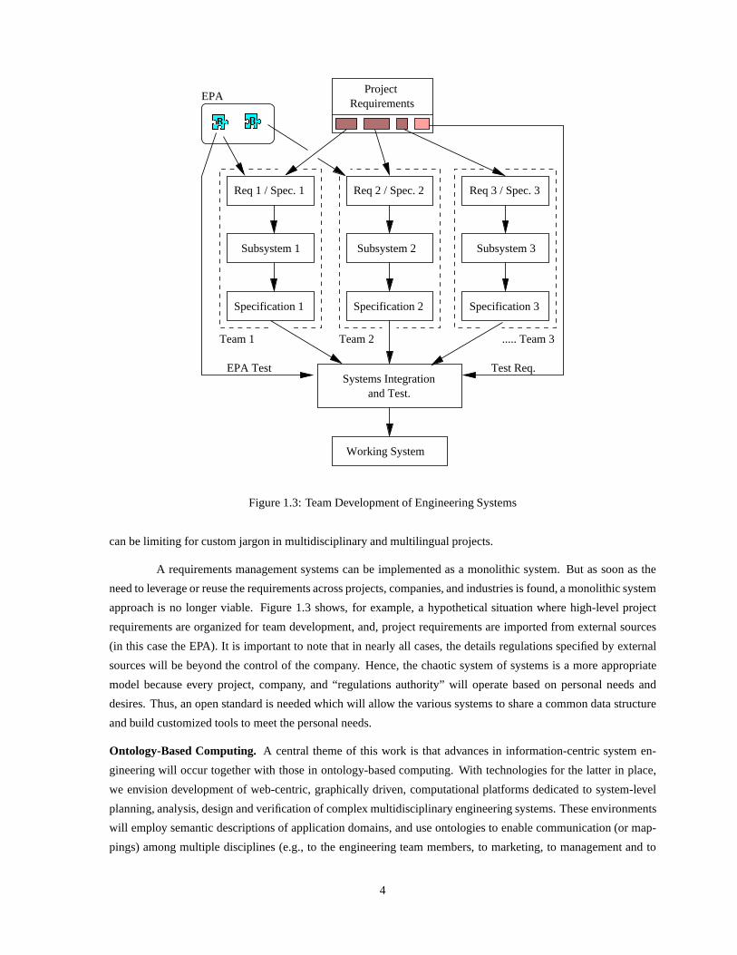
Figure 1.3: Team Development of Engineering Systems
can be limiting for custom jargon in multidisciplinary and multilingual projects.
A requirements management systems can be implemented as a monolithic system. But as soon as the
need to leverage or reuse the requirements across projects,companies, and industries is found, a monolithic system
approach is no longer viable. Figure 1.3 shows, for example,a hypothetical situation where high-level project
requirements are organized for team development, and, project requirements are imported from external sources
(in this case the EPA). It is important to note that in nearly all cases, the details regulations specified by external
sources will be beyond the control of the company. Hence, thechaotic system of systems is a more appropriate
model because every project, company, and “regulations authority” will operate based on personal needs and
desires. Thus, an open standard is needed which will allow the various systems to share a common data structure
and build customized tools to meet the personal needs.
Ontology-Based Computing. A central theme of this work is that advances in information-centric system en-
gineering will occur together with those in ontology-basedcomputing. With technologies for the latter in place,
we envision development of web-centric, graphically driven, computational platforms dedicated to system-level
planning, analysis, design and verification of complex multidisciplinary engineering systems. These environments
will employ semantic descriptions of application domains,and use ontologies to enable communication (or map-
pings) among multiple disciplines (e.g., to the engineering team members, to marketing, to management and to
4

−− What is the architecture of the integrated system?
System−Level Architecture and Performance Assesment
Back−end support for system−level architecture and performance assessment.
Domain 1
Domain 2
Domain−specific descriptions (e.g, UML, block diagrams)
of system content.
Vis
ual
izat
ion
Map
pin
gs
Integrated view of system architecture
with realtime rule checking.
Invalid Parameters
Mappings
Technical
−− Is the system layout consistent with standards/design code requirements?
−− Are two design alternatives logically equivalent?
−− Can the system structure be simplified?
−− Which system operations can operate concurrently?
−− What will the system do?
−− Can the system work?
Figure 1.4: Looking Ahead – Integration of Application-Specific Viewpoints of Engineering Systems, with back-end support for System-Level Architecture and PerformanceAssessment
customers). They will provide support for the integration of application-specific viewpoints of engineering sys-
tems, with backend support for system-level architecture and performance assessment. See Figure 1.4. Present-day
systems engineering methodologies and tools are not designed to handle projects in this way.
1.2 Scope and Objectives
This report is the second in a series on “Requirements Engineering and the Semantic Web.” In Part
1, Selberg et al. [48] identify an opportunity for using technologies in the Semantic Web Layer Cake to mitigate
limitations in present-day systems engineering tools. A prototype XML/RDF traceability browser is presented. The
objectives for this study are to explore further the application of RDF, ontologies and logic for the representation,
management, and validation of requirements and system-level architectures. Accordingly, the plan of work for this
report is as follows:
1. Representation and management of requirements. See Chapter 2.
2. Representation and synthesis of system-level architectures from reusable component-specifications. See Chap-
ter 3.
5

specifications.Product
Productspecifications.
Productspecifications.
www.panasonic.com
www.jbl.com
www.sony.com
Partially assembled system
External Description of Product Specifications
Textual description of requirements.Graphical description of relationshipamong requirements.
Power
Plasma Screen Display
Figure 1.5: Synthesis of System Architectures Enabled by Product Descriptions on Web. Here we show a simplifiedarchitecture for the home theater system developed in Chapter 4.
3. Ontology-enabled validation of system architectures. SeeChapter 5.
This project is motivated, in part, by the need to develop methodologies and tools for the synthesis, management,
and visualization of system-level architecture likely to be found in the NASA Global Precipitation Measurement
(GPM) project [22]. Briefly, NASA’s GPM project is “one of thenext generation of systematic measurement
missions that will measure global precipitation, a key climate factor, with improved temporal resolution and spatial
coverage.” The implementation of NASA GPM is a multi-national effort that will require the launch and operation
of at least seven satellites and the participation of at least five countries. The system design and implementation
will occur through 2018.
As a first step, we are prototyping our ideas and techniques ona simpler problem – representation and
bottom-up synthesis of components in a home theater system.We envision development of a design environment
where customers can formulate detailed requirements for the home theater system that they want to purchase, and
then download descriptions of electronic components over the web. Detailed descriptions of flat panel displays
might be available at www.panasonc.com, amplifiers at www.sony.com, and so forth. See Figure 1.5. The speci-
fications attached to each electronic component will be usedin a number of ways. At a basic level, statements of
component performance can be directly compared to customerrequirements. But component specifications also
include information on requirements for the system to work.The design environment should be able to detect
incompatibilities in interface requirements and make appropriate suggestions for resolving conflicts. At even a
higher-level of abstraction, component specifications include suggestions for system assembly (e.g., system archi-
tectures that the manufacturer believes are good). Hence, the design environment should make suggestions to the
designer on how components might best be configured for optimal operation.
6

1.3 The Semantic Web
In his original vision for the World Wide Web, Tim Berners-Lee described two key objectives: (1)
To make the Web a collaborative medium; and (2) To make the Webunderstandable and, thus, processable by
machines.
During the past decade the first part of this vision has come topass – today’s Web provides a medium for
presentation of data/content to humans. Machines are used primarily to retrieve and render information. Humans
are expected to interpret and understand the meaning of the content. Automating anything on the Web (e.g.,
information retrieval; synthesis) is difficult because interpretation in one form or another is required in order for
the Web content to be useful. Current information retrievaltechnologies are incapable of exploiting the semantic
knowledge within documents and, hence, cannot give preciseanswers to precise questions. (Indeed, since web
documents are not designed to be understood by machines, theonly real form of search is full-text searching.)
The Semantic Web [6, 24] is an extension of the current web. Itaims to give information a well-defined
meaning, thereby creating a pathway for machine-to-machine communication and automated services based on
descriptions of semantics [20]. Realization of this goal will require mechanisms (i.e., markup languages) that
will enable the introduction, coordination, and sharing ofthe formal semantics of data, as well as an ability to
reason and draw conclusions (i.e., inference) from semantic data obtained by following hyperlinks to definitions
of problem domains (i.e., so-called ontologies).
1.3.1 Technologies in the Semantic Web Layer Cake
During a talk at the XML World 2000 Conference in Boston, Massachusetts, the World Wide Web
Consortium (W3C) head Tim Berners-Lee presented the Semantic Web Layer Cake diagram (see Figure 1.6) to
describe the infrastructure that will support this vision [5].
1.3.2 The URI and Unicode Layer
The bottom layer of this cake is constructed of Universal Resource Identifiers (URI) [56] and Unicode
[55]. URIs are a generalized mechanism for specifying a unique address for an item. They provide the basis for
linking information on the Internet. Unicode is the 16-bit extension of ASCII text – it assigns a unique platform-
independent and language-independentnumber to every character, thereby allowing any language to be represented
on any platform.
1.3.3 The eXtensible Markup Language (XML) Layer
The eXtensible Markup Language (XML) [7] provides the fundamental layer for representation and
management of data on the Web. The technology itself has two aspects. It is an open standard which describes
how to declare and use simple tree-based data structures within a plain text file. XML is not a markup language,
but a meta-language (or set of rules) for defining domain- or industry-specific markup languages. A case in
point is the Mathematical Language Specification (MathML) [40]. MathML is an XML application for describing
mathematical notation and capturing both its structure andcontent. A second example is the scalable vector
7

Universal ResourceIdentifiers
Unicode
XML - Structured documentsNamespaces + XML-Schema
Resource DescriptionFramework + Schema
Ontology Support
Logic
Proof
Dig
ital
Sig
nat
ure
Trust
Self-describingDocument
Data
Data
Rules
Semantic Web Layers
Technical Maturity
Well Known
Evolving
Figure 1.6: Technical Maturity of the Semantic Web Layer Cake
graphics (SVG) markup language [51], which defines two-dimensional vector graphics in a compact text format.
Hence, on a more conceptual plane, XML is a strategy for information management.
XML is defined only at the syntax level. A well-formed XML document defines a tree of nested sets
of open and close tags, each of which can include several attribute-value pairs. The rules of “well-formedness,”
which are the nuts and bolts part of XML, provide enough information that generic code modules, called parsers,
can be developed to read, write, and manipulate the XML files.An example of such a parser is the open source
Xerces parser [61]. The parsers can be built into other applications, such as Microsoft Word or Adobe Illustrator
[2, 60], giving them the power to work with XML files. The “well-formed” criteria guarantees that the parser can
read the XML file, but from the application’s point of view, itdoes not give any confidence that the data in the
XML file will be complete or consistent. To solve this problem, the basic form constraint can be extended through
the use of Document Type Definitions (DTDs) or Schema. Both ofthese technologies are ways of specifying the
rules and structure to which the XML document must also conform. For example, XHTML, an XML compliant
variant of HTML, is defined by both the XML definition and the XHTML DTD [62].
On the conceptual level, XML asks that content and form (or presentation) be separated. The real
beauty in representing data/information in XML is that we can filter or sort the data or re-purpose it for different
devices using the Extensible Stylesheet Language Transformation (XSLT). For example, a single XML file can be
presented to the web and paper through two different style sheets. This saves duplication of work and reduces the
risk of error.
Example. XML Model of an Individual Requirement. In an effort to classify requirements for reuse across
projects, and attach semantics to requirements, the concept of requirements boilerplates has been proposed by Hull
et al. [26]. For example, an instance of the template:
8

The<specification> of <object> shall not exceed<value> <units>
represented in XML might look like:
- <Requirement ID="REQ.3.2"><Name Value="Thickness of TV" /><Rationale Value="Comes from Wall mountable display scree n" /><Verification Value="Demonstration" /><Comment Value="Component Level Requirement" /><REVISION Value="Mon Jun 16 14:00:55 EDT 2003" /><MAPPED_TO Value="TV" /><Template NO="1" OBJECT="TV" SPECIFICATION="Thickness" SPECLINK="tv1.xml"
VALUE1="6" UNITS="inches" /><Description Value="Thickness of the TV shall not exceed 6 i nches" /></Requirement>
Here, the XML representation supports the following requirements attributes: (1) Unique identifier; (2) A descrip-
tive name of the requirement; (3) Rationale; (4) Verification Strategy; (5) Comment; (6) Creation/last modified
date; (7) Description of the Requirement (Text), and (8) Template attribute/value pairs on which the requirement
is based. The requirement attributes and their values can bestored in an XML file (e.g.,ReqDoc.xml ).
Requirements processing can proceed in a number of directions. One possibility is to generate require-
ments documentation directly from the XML markup by applying an appropriate XSLT [63] transformation. Al-
ternatively, a Java parser, such as Xerces [61], can be written to extract the value of the attributes and display them
in the graphical user interface.
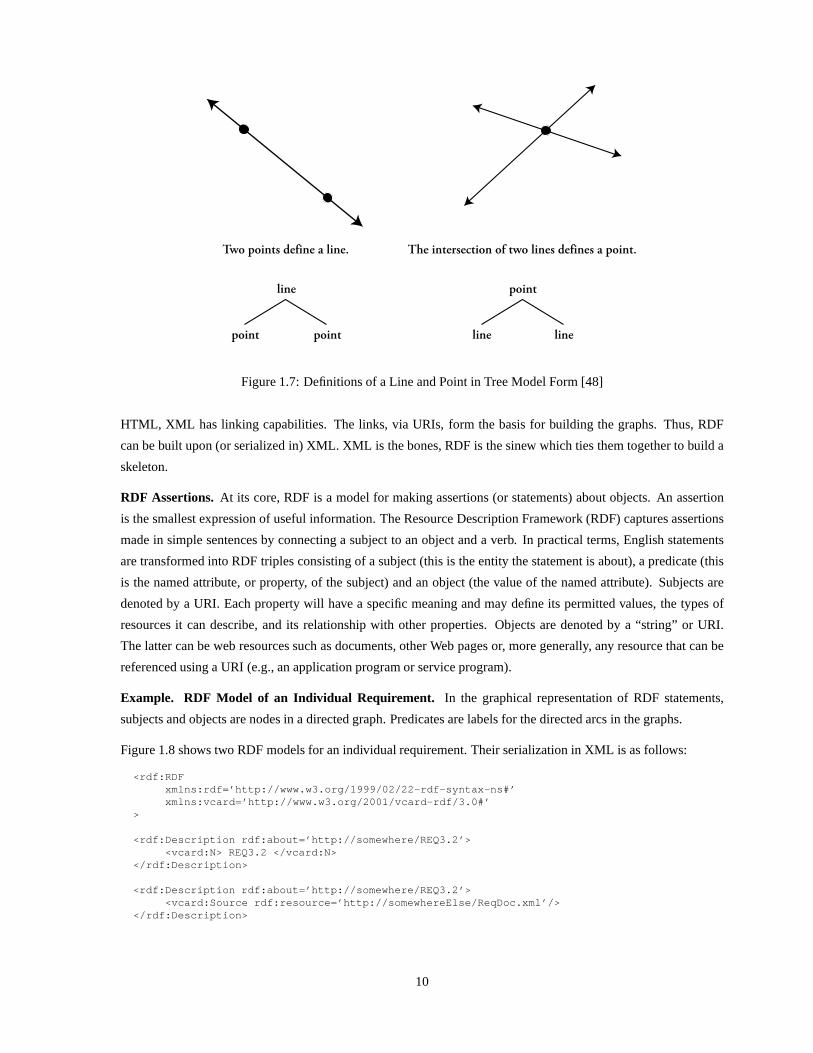
Limitations of XML . While XML provides support for the portable encoding of data, it is limited to information
that can organized within hierarchical relationships. A common engineering task is the synthesis of information
from multiple data sources. This can be problematic for XML as a synthesized object may or may not fit into a
hierarchal model. Suppose, for example, that within one domain a line is defined by two points, and in a second
domain, a point is defined by the intersection of two lines. These definitions and the resulting tree models are
illustrated in Figure 1.7. Merging these models results in acircular reference – the resultant tree model is therefore
infinite. XML can not directly support the merger of these twomodels. A graph, however, can. Thus, we introduce
the Resource Description Framework.
1.3.4 The Resource Description Framework (RDF) Layer
The Resource Description Framework (RDF) is a graph-based (assertional) data model for describing
the relationships between objects and classes in a general but simple way. For the Semantic Web, the primary use
of RDF will be to encode metadata – for example, information such as the title, author, and subject – about Web
resources in a schema that is sharable and understandable. Due to RDF’s incremental extensibility, the hope is that
software agents processing metadata will be able to trace the origins of schema they are unfamiliar with to known
schema and, thus, will be able to perform actions on metadatathey weren’t originally designed to process.
From an implementation standpoint, the capabilities of RDFand XML are complementary. RDF defines
a graph-based object model for metadata, and API support forgraph operations (e.g., union, intersection). XML
API’s provide no such capability. On the other hand, RDF onlysuperficially addresses many encoding issues
for transportation – for these aspects, RDF employs XML as the serialization syntax. More specifically, as with
9
Two points define a line.
line
point point
The intersection of two lines defines a point.
point
line line
Figure 1.7: Definitions of a Line and Point in Tree Model Form [48]
HTML, XML has linking capabilities. The links, via URIs, form the basis for building the graphs. Thus, RDF
can be built upon (or serialized in) XML. XML is the bones, RDFis the sinew which ties them together to build a
skeleton.
RDF Assertions. At its core, RDF is a model for making assertions (or statements) about objects. An assertion
is the smallest expression of useful information. The Resource Description Framework (RDF) captures assertions
made in simple sentences by connecting a subject to an objectand a verb. In practical terms, English statements
are transformed into RDF triples consisting of a subject (this is the entity the statement is about), a predicate (this
is the named attribute, or property, of the subject) and an object (the value of the named attribute). Subjects are
denoted by a URI. Each property will have a specific meaning and may define its permitted values, the types of
resources it can describe, and its relationship with other properties. Objects are denoted by a “string” or URI.
The latter can be web resources such as documents, other Web pages or, more generally, any resource that can be
referenced using a URI (e.g., an application program or service program).
Example. RDF Model of an Individual Requirement. In the graphical representation of RDF statements,
subjects and objects are nodes in a directed graph. Predicates are labels for the directed arcs in the graphs.
Figure 1.8 shows two RDF models for an individual requirement. Their serialization in XML is as follows:
<rdf:RDFxmlns:rdf=’http://www.w3.org/1999/02/22-rdf-syntax- ns#’xmlns:vcard=’http://www.w3.org/2001/vcard-rdf/3.0#’
>
<rdf:Description rdf:about=’http://somewhere/REQ3.2’ ><vcard:N> REQ3.2 </vcard:N>
</rdf:Description>
<rdf:Description rdf:about=’http://somewhere/REQ3.2’ ><vcard:Source rdf:resource=’http://somewhereElse/Req Doc.xml’/>
</rdf:Description>
10

vcard:N
PredicateSubject Object
Requirement represented by a label
PredicateSubject Object
REQ3.2http://somewhere/REQ3.2
http://somewhere/REQ3.2
Requirement template stored in an XML file ReqDoc.xml
http://somewhereElse/ReqDoc.xmlvcard:Source
Figure 1.8: RDF Models of an Individual Requirement. In the node and arc diagram, ovals can represent botha subject and object. Rectangular boxes always represent objects. The direction of the arrow is always from thesubject to the object of the statement.
The first block of code defines the XML namespaces and shorthand prefixes that can be used in the RDF statements.
In both representations of the requirement, the subject of the statement is located at URI
http://somewhere/REQ3.2
In the upper model, the predicatevcard:N refers to a name. The object is simply a label corresponding to the
name of the requirement. The statement should be read “http://somewhere/REQ3.2 has the label REQ3.2.”
In the lower model, the predicatevcard:Source refers to a source file. The object is a URI for the
XML file containing a complete description of the requirement, that is,
http://somewhereElse/ReqDoc.xml
The statement should be read “http://somewhere/REQ3.2 hasthe source file http://somewhereElse/ReqDoc.xml.”
Limitations of RDF. A key limitation of RDF is poorly defined semantics. RDF has nosense of vocabulary. It
does not provide any notion of scope within which a specified vocabulary can be constrained. Any node within a
connected RDF graph is reachable by any other node. To support automated reasoning, agreement on a uniform,
well defined, vocabulary is needed.
1.3.5 Ontologies
According to James Hendler, a leading researcher of the Semantic Web, an ontology is “a set of knowl-
edge terms, including the vocabulary, the semantic interconnections, and some simple rules of inference and logic
for some particular topic [23, 24].” Ontologies are needed to facilitate communication among people, among
machines, and between humans and machines.
So what does an ontology look like? It’s a question the Internet community is still struggling with.
Some envision “ a few large, complex, consistent ontologies.” Others see “a great number of small ontological
components consisting largely of pointers to each other [24].” In either case, ontologies help to bridge the gap
11
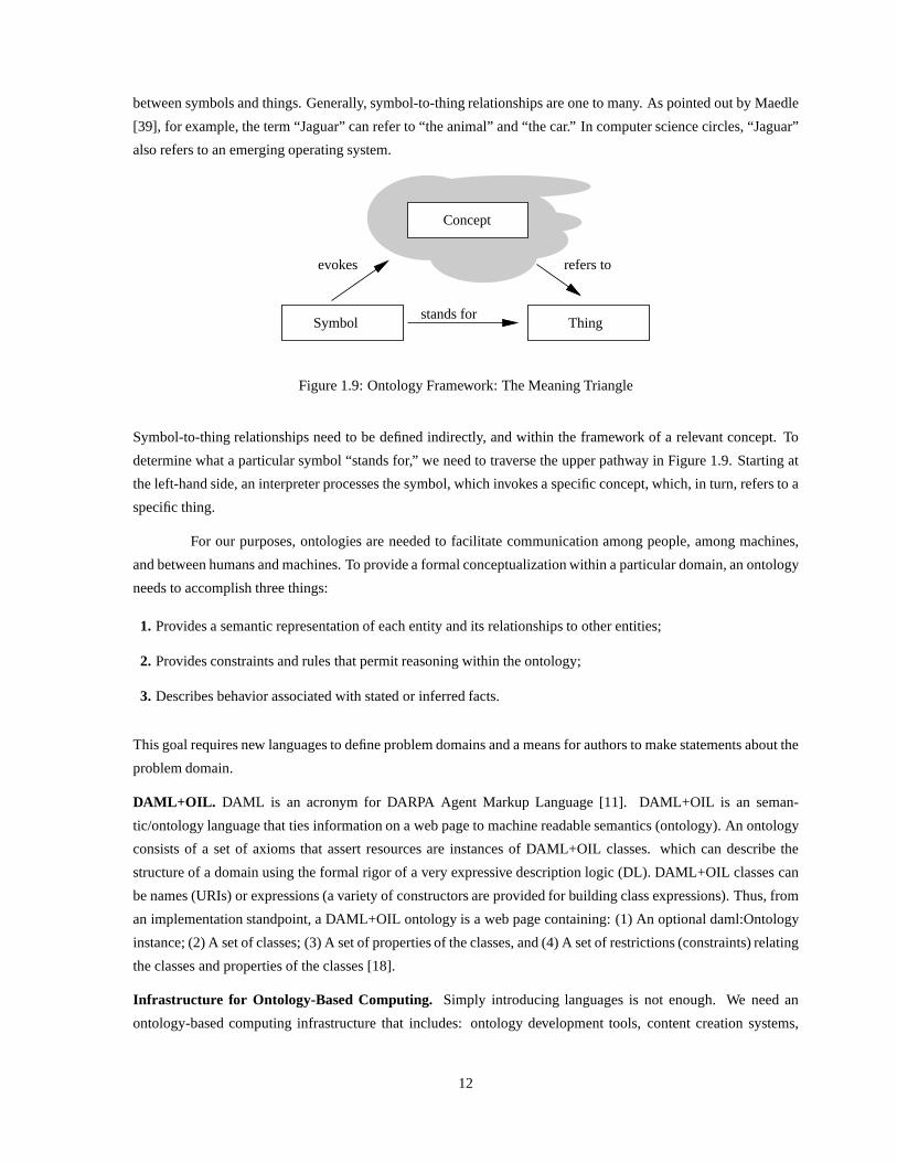
between symbols and things. Generally, symbol-to-thing relationships are one to many. As pointed out by Maedle
[39], for example, the term “Jaguar” can refer to “the animal” and “the car.” In computer science circles, “Jaguar”
also refers to an emerging operating system.
ThingSymbol
Concept
stands for
refers toevokes
Figure 1.9: Ontology Framework: The Meaning Triangle
Symbol-to-thing relationships need to be defined indirectly, and within the framework of a relevant concept. To
determine what a particular symbol “stands for,” we need to traverse the upper pathway in Figure 1.9. Starting at
the left-hand side, an interpreter processes the symbol, which invokes a specific concept, which, in turn, refers to a
specific thing.
For our purposes, ontologies are needed to facilitate communication among people, among machines,
and between humans and machines. To provide a formal conceptualization within a particular domain, an ontology
needs to accomplish three things:
1. Provides a semantic representation of each entity and its relationships to other entities;
2. Provides constraints and rules that permit reasoning within the ontology;
3. Describes behavior associated with stated or inferred facts.
This goal requires new languages to define problem domains and a means for authors to make statements about the
problem domain.
DAML+OIL. DAML is an acronym for DARPA Agent Markup Language [11]. DAML+OIL is an seman-
tic/ontology language that ties information on a web page tomachine readable semantics (ontology). An ontology
consists of a set of axioms that assert resources are instances of DAML+OIL classes. which can describe the
structure of a domain using the formal rigor of a very expressive description logic (DL). DAML+OIL classes can
be names (URIs) or expressions (a variety of constructors are provided for building class expressions). Thus, from
an implementation standpoint, a DAML+OIL ontology is a web page containing: (1) An optional daml:Ontology
instance; (2) A set of classes; (3) A set of properties of the classes, and (4) A set of restrictions (constraints) relating
the classes and properties of the classes [18].
Infrastructure for Ontology-Based Computing. Simply introducing languages is not enough. We need an
ontology-based computing infrastructure that includes: ontology development tools, content creation systems,
12

storage and retrieval systems, ontology reasoning and mediation, and lastly, integration of reasoning with real-
world applications! For preliminary work on development ofontology tools, see references [21, 32, 33, 50].
Ontologies that will enable application interoperabilityby resolving semantic clashes between application domains
and standards/design codes are currently in development [9, 34].
For this vision to become practical, ontology-based technology must be scalable. This means that issues
associated with the “expressiveness of description logic”must be balanced against “tractability of computation.”
While the syntax of first-order logic is designed to make it easy to say “things about objects,” predicting the solu-
tion time for evaluation of statements written in standard first-order logic is often impossible. Description logics
(DLs), on the other hand, emphasize “categories, their definitions, and relations,” and are designed specifically
for tractability of inference [4]. Description logics ensure that subsumption testing (inference) can be solved in
polynomial time with respect to the size of the problem description.
1.3.6 Logic (and Rules)
From this point on, and as indicated in Figure 1.6, we’re discussing parts of the Semantic Web that are
still being explored and prototyped. While it’s nice to havesystems that understand basic semantic and ontological
concepts (subclass, inverse, etc.), it would be even betterif we could create logical statements (rules) that allow
the computer to make inferences and deductions. Reasoning with respect to deployed ontologies will enhance
“intelligent agents” allowing them to determine, for example, if a set of facts is consistent with respect to an
ontology, to identify individuals that are implicitly members of given class, and so forth.
1.3.7 Digital Signatures
Digital signatures are based on work in mathematics and cryptography, and provide proof that a certain
person wrote (or agrees with) a document or statement.
1.3.8 Proof, Trust, and Beyond
Because the Semantic Web is an open and distributed system, in principle, anybody can say anything
about anybody. To deal with the inevitable situation of unreliable and contradictory statements (data and infor-
mation) on the Semantic Web, there needs to be a mechanism where we can verify that the original source does
make a particular statement (proof) and that source is trustworthy (trust). At this point, notions of proof and trust
have yet to be formalized, and a theory that integrates them into inference engines of the Semantic Web have yet
to be developed. However, these advances in technology willoccur, simply because they are a prerequisite to the
building of real commercial applications.
The ability to “prove things” on the Semantic Web stems directly from its support for logical reasoning.
When this system is operational, different people all around the World will write logic statements. Then, machines
will follow these Semantic “links” to begin to prove facts. Swartz and Hendler [52] point out that while it is very
difficult to create these proofs (it could require followingthousands, or perhaps millions of the links in the Semantic
Web), it’s very easy to check them. In this way, we begin to build a Web of information processors. Some of them
could merely provide data for others to use. Others would be smarter, and could use this data to build rules. The
13

Figure 1.10: Architecture of Paladin integrated with Ontology-Based Rule Checking. For more details, see refer-ence [36]
smartest would be heuristic engines, powering “intelligent agents” which follow all these rules and statements to
draw conclusions, and place their results back on the Web as proofs as well as data or query answers like those
shown in the introduction [38].
Looking ahead, the desired goal for the the Semantic Web is armys of software agents which know about
logic, and with the support of the ontology, can then use RDF to navigate the sea of XML documents and perform
logical reasoning tasks on behalf of a user. Each agent will probably have a very limited scope. Perhaps an agent
knows how to find available times at the doctor’s office for an appointment. A second agent may know how to find
available times in your personal schedule. A third agent mayknow how to ask the other two for available times
and find a common one. A fourth agent may know how to tell agents5 and 6 to add the appointment the doctor’s
schedule and your personal calendar. The key to the inference services is not in a very complex agent, but an army
of simple agents who can use the Semantic Web infrastructureto communicate.
1.4 Organization of this Report
This report is divided into six chapters. Chapter 2 covers issues associated with the representation and
management of requirements. It provides a formal frameworkto specify the XML/RDF schema and template
14

structure to store the requirements. With this formal representation, approach for controlled visualization of re-
quirements hierarchy-using RDQL is outlined.
Chapter 3 deals with the representation and synthesis of system-level architectures from reusable component-
specification pairs. Procedures for the bottom-up assemblyand synthesis of system-level architectures from
reusable component specification are developed. An RDF model is developed to store the connectivity information
among the objects. Object specifications are translated to an XML schema. The former can be checked against
requirements. Associated issues include support for multiple viewpoints of the system architecture, merging of
sub-systems, and so forth. We formulate an XML schema that will store the visual properties of an object.
Chapter 4 contains a working example of a home theater system. Its main purpose is to illustrate all the
concepts outlined in Chapters 2 and 3.
Chapter 5 investigates the application of “ontologies and reasoning” to the solution of engineering prob-
lems. We want to understand the extent to which relationships and constraints in ontology-based descriptions of
problem domains can influence and improve system-level design procedures. A Port-Jack ontology is developed
for the home theater system. Class relationships and the domain restriction between the Port and Jack specify what
kind of connections are permitted. This fact base is translated to Jess input, and rules are added on the basis of the
instances created in GUI.
1.5 Acknowledgments
This work was supported in part by the National Science Foundation’s Combined Research and Curricu-
lum Development Program (NSF CRCD), an educational grant from the Global Precipitation Measurement Project
at the NASA Goddard Space Flight Center, and the Lockheed Martin Corporation. We particularly wish to thank
David Everett and Tom Philips at NASA Goddard for their inputto the systems engineering and software devel-
opment phases of this project. The views expressed in this report are those of the writers and are not necessarily
those of the sponsors.
15

Chapter 2
Representation and Management ofRequirements
The basic building block of object-oriented system development is assessment of customer needs in the
form of goals and scenarios, followed by their conversion into high-level requirements. Requirements define what
the stakeholders - owners, users, and customers - expect from a new system. Satisfying the needs of all stakeholders
may be far from trivial - their demands of the system may be many, and in some cases, conflicting in nature. So in
order to achieve a proper system design it becomes absolutely essential to have a formal structural framework in
place to manage and enforce project requirements that are consistent and unambiguous.
2.1 Organization of Requirements
Requirements are organized so that they can easily support separation of concerns and top-down decom-
position in system development. For many present-day developments, these organizational concerns translate into
documents containing hierarchies of stakeholder requirements dictating the needs of the overall system (e.g., func-
tional requirements, interface requirements). Often, these high-level requirements are termed Level 0 requirements,
or sometimes, the mission statements of the system.
A common practice in systems engineering circles is population of requirements engineering databases
through the parsing and import of textual (requirements) documents, such as those prepared in Microsoft Word.
While many systems engineers find this pathway of requirements preparation convenient, the resulting require-
ments are largely abstract in nature, lack semantics, and may not be quantifiable. It is therefore the job of the
systems engineer to break down these higher-level requirements into lower-level requirements suitable for quanti-
tative evaluation.
2.2 Requirements Allocation and Flowdown
Allocation involves the breaking of a single attribute value into parts, and assigning values to subordinate
values. For example, overall system budget is a constrainedresource that is divided and allocated to components
making up the system structure. Thus, as shown in the lower half of Figure 2.1, requirements allocation is the
16

StakeholderRequirements
SystemRequirements
SubsystemRequirements
ComponentRequirements
ComponentTest
SubsystemTest
SystemTest
TestStakeholder
Allocate requirementsto components.
Flowdown ofRequirements
Verify the system
Validate the system
Validate the system
Figure 2.1: Flowdown of Requirements in the V-Model of System Development (Adapted from Hull et al. [26])
process of allocating a set of unique requirements to one or more subsystems or components.
Higher-level requirements are made more granular by refining and breaking them down at various levels.
The goal of this “flowdown process” is to successively define the complying requirements until a state is reached
where a particular requirement can be assigned to a single component. Typically, different teams/persons are
responsible for various layers of requirements. So once allthe requirements mapped to a particular component are
identified, a team can be assigned to design that particular component.
2.3 Graph Representation of Requirements
Present-day systems engineering tools such as SLATE graphically represent the complying and defining
requirements in a tree structure with respect to the requirement of interest. This model works well if requirements
comply/define from a single source. In practice, however, asrequirements are classified and broken down into more
granular components, they trace across the same level. Thishappens because requirements are tightly interdepen-
dent with each other across the same level of abstraction. Asa result, within the same level, one requirement may
comply or define the other requirements. A partial requirement document with requirements arranged in layers is
shown in Figure 2.2.
Figure 2.3 shows the tree structure of a complying requirement relationship modeled in SLATE [1]. In
this particular example, provided by the GPM Project Group at NASA Goddard, there are repetitions of the node
GPM Microwave Imager under the Sampling Requirement. This happens because of the inherent limitation of
trees in representing complex requirements structures and, in part, because systems engineers like to work with
data/information organized into tree structures – for example, a tree structure naturally occurs when paragraphs,
requirements, and so forth are extracted from a Word document. Even if initial requirements are written in a
tree structure format, relationships among requirements (i.e., links) are progressively modified as the requirements
17

Layer 1
Layer 3
Layer 2
E
E
E
C
C
C
into a graph.the tree representation
Compaction of
Requirements are organized into layers
for team development.
E
C
Flo
wdo
wn
E
Figure 2.2: Many-to-Many Relationships in Layers of Requirements. On the right-hand side we show extractionand visualization of requirements as a tree, followed by compaction back in to a graph format.
Figure 2.3: Tree Representation of Requirements in SLATE (Source: Dave Everett, NASA Goddard)
18

evolve. This renders the underlying structure of the requirements document as a graph instead of a tree. Hence,
from this point on partial tree structure views of the requirements document are likely to require duplication of the
leaf nodes.
2.4 Requirement Template Structure
As pointed out by Hull et al. [26], in writing a requirements document, two aspects have to be carefully balanced:
1. The need to make the requirements document readable;
2. The need to make the set of requirements processable.
While requirements written in a text editor can be readable and can be easily imported into many systems-
engineering tools, a fundamental limitation is lack of semantics associated with each requirement. In an effort
to mitigate the latter limitation, and enable classification and reuse of requirements across several projects, the
concept of boilerplates has been proposed by Hull et al. [26].
In this project, we interpret the concept of boilerplates astemplates. Templates provide users with
placeholders to provide input on the values of requirementsattributes. As a first step, templates are provided for
the requirements relevant in the context of the system structure diagram. Furthermore, we assume that almost all
the requirements can be written in a primitive format i.e,
<attribute, relation, and value>.
For example, a weight requirement on a particular componentmay state that the mass of the component shall not
exceed 10 lbs. This in essence translates to
<Mass <= 10>
By gathering the values from the placeholders consistent requirement statements can be generated automatically.
Template Definitions
There is another clear advantage of using the templates in the system structure context. As we will soon
see, we can use this information to support the bottom-up system development. The following templates have been
specified with respect to the system structure:
1. The<specification> of <object> shall not exceed<value> <units>
2. The<specification> of <object> shall be less than<value> <units>
3. The<specification> of <object> shall be at least<value> <units>
4. The<specification> of <object> shall be greater than<value> <units>
5. The<specification> of <object> shall lie within<lesser value> and<higher value> units
19
6. The<specification> of <object> shall be<value (numeric)> <units>
7. The<specification> of <object> shall be<value (alphanumeric)> <units>
8. The<originating port> of <object> shall connect to<destination port> at the other end.
Since it is not possible to represent the entire requirements document (for example behavior requirements, or
the higher-level requirements that are abstract and often non-quantifiable) within the framework of these eight
templates, template 0 is reserved for the representation of“all other” requirements. Requirements at the lowest
level in the hierarchy (leaf requirements) are mapped to individual components in the system structure. These
requirements are in turn grouped on the basis of the components to which they are mapped, and assigned to either
teams or to sub-contractors for the final design of the component. Most of these requirements are checked against
the existing component specifications (possibly among a pool of available choices for that component to promote
reuse), before the designer comes up with a final component that matches the requirements mapped to it.
Templates add semantics to the individual requirements andin turn can be processed to check the spec-
ifications of the components against them. This results in considerable time savings and increases in productivity.
Unfortunately, the practice of checking requirements against component specification is still manual. As systems
grow more complex, the number of checks to be performed can quickly become unmanageable. In Chapter 4, we
develop a complete working example that has a graphical userinterface and automated checking of requirements
written in a template format.
2.5 XML and RDF Representation of Requirements
Depending upon various projects needs, requirements have different attributes associated with them. For
example, some of the attributes might be verification method, description of requirement, creator, priority and ra-
tional, and so forth. These attributes are customizable depending on the particular vision of documenting a set of
requirements. The extensible markup language (XML) can be used to store the attributes and their value. Require-
ments processing can proceed in a number of directions. One possibility is to generate requirements documentation
directly from the XML markup by applying an appropriate XSLT[63] transformation. Alternatively, a Java parser,
such as Xerces [61], can be written to extract the value of theattributes and display them in the graphical user
interface.
Representation of System Requirements
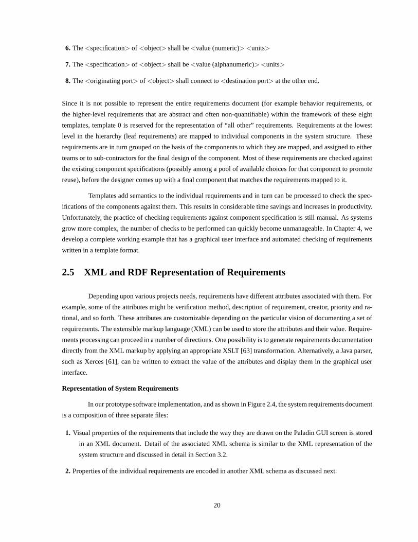
In our prototype software implementation, and as shown in Figure 2.4, the system requirements document
is a composition of three separate files:
1. Visual properties of the requirements that include the way they are drawn on the Paladin GUI screen is stored
in an XML document. Detail of the associated XML schema is similar to the XML representation of the
system structure and discussed in detail in Section 3.2.
2. Properties of the individual requirements are encoded in another XML schema as discussed next.
20

Figure 2.4: Internal Representation of Requirements
3. The connectivity information among various requirement objects are stored in a RDF file, discussed in Section
2.7.
XML Tag Set for Representation of Requirements
To start with we consider the following attributes of a particular requirement:
1. Unique identifier
2. A descriptive name of the requirement
3. Rationale
4. Verification Strategy
5. Comment
6. Creation/last modified date
7. Description of the Requirement (Text), and
8. Template on which the requirement is based (As defined in Section 2.4)
Example 1.Based on the above information, a sample requirement encoding in XML might be as follows:
<Requirement ID="REQ.2.1"><Name Value="Display Requirement" /><Rationale Value="Need to watch movies on large screen" /><Verification Value="Demonstration" />
21
<Comment Value="Detailed agreement between the customer a nd builder" /><REVISION Value="Mon Jun 16 14:00:55 EDT 2003" /><MAPPED_TO Value="TV" /><Template NO="0" /><Description Value="The Home Theater shall have a large dis play screen" />
</Requirement>
Because this requirement is a higher-level abstract requirement, we use the generic template 0 for its encoding in
XML.
Example 2.A lower-level requirement.
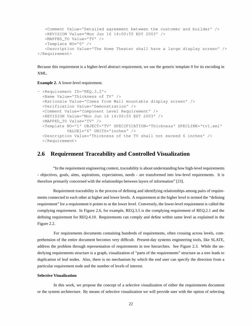
- <Requirement ID="REQ.3.2"><Name Value="Thickness of TV" /><Rationale Value="Comes from Wall mountable display scree n" /><Verification Value="Demonstration" /><Comment Value="Component Level Requirement" /><REVISION Value="Mon Jun 16 14:00:55 EDT 2003" /><MAPPED_TO Value="TV" /><Template NO="1" OBJECT="TV" SPECIFICATION="Thickness" SPECLINK="tv1.xml"
VALUE1="6" UNITS="inches" /><Description Value="Thickness of the TV shall not exceed 6 i nches" /></Requirement>
2.6 Requirement Traceability and Controlled Visualization
“In the requirement engineering context, traceability is about understanding how high-level requirements
- objectives, goals, aims, aspirations, expectations, needs - are transformed into low-level requirements. It is
therefore primarily concerned with the relationships between layers of information” [23].
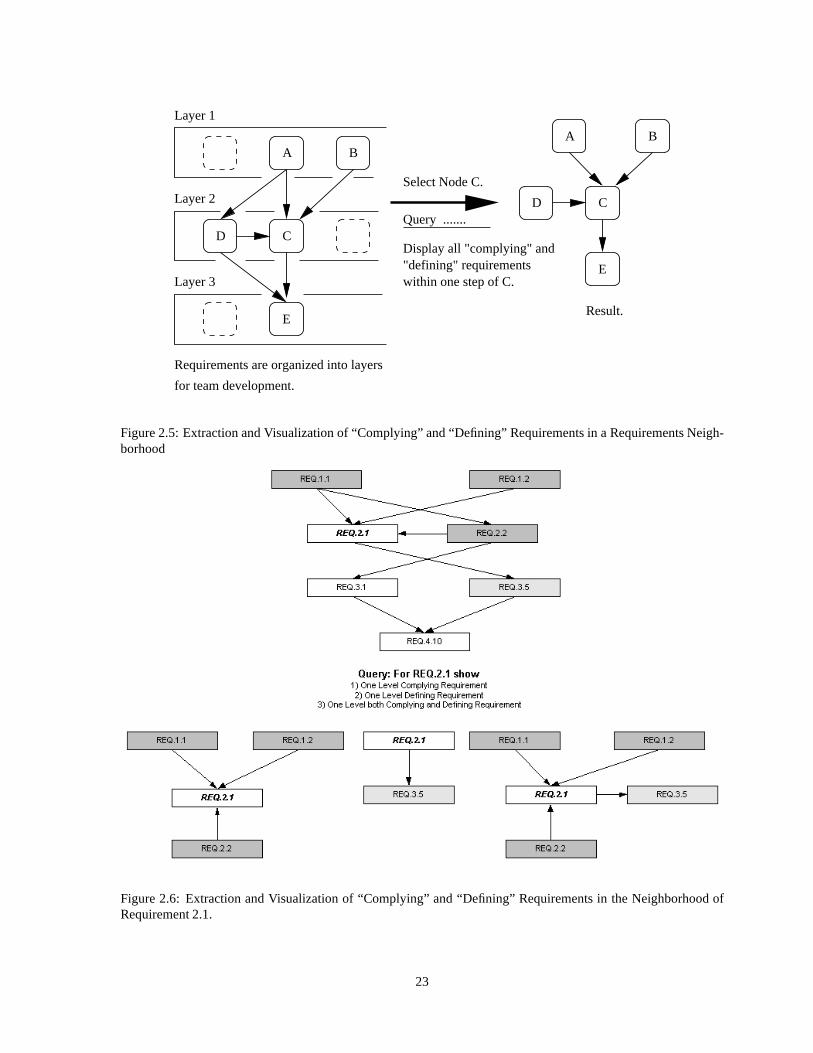
Requirement traceability is the process of defining and identifying relationships among pairs of require-
ments connected to each other at higher and lower levels. A requirement at the higher level is termed the “defining
requirement” for a requirement it points to at the lower level. Conversely, the lower-level requirement is called the
complying requirement. In Figure 2.6, for example, REQ.3.5is the complying requirement of REQ.2.1 and the
defining requirement for REQ.4.10. Requirements can complyand define within same level as explained in the
Figure 2.2.
For requirements documents containing hundreds of requirements, often crossing across levels, com-
prehension of the entire document becomes very difficult. Present-day systems engineering tools, like SLATE,
address the problem through representation of requirements in tree hierarchies. See Figure 2.3. While the un-
derlying requirements structure is a graph, visualizationof “parts of the requirements” structure as a tree leads to
duplication of leaf nodes. Also, there is no mechanism by which the end user can specify the direction from a
particular requirement node and the number of levels of interest.
Selective Visualization
In this work, we propose the concept of a selective visualization of either the requirements document
or the system architecture. By means of selective visualization we will provide user with the option of selecting
22
Layer 1
Layer 3
Layer 2
E
C
C
Requirements are organized into layers
for team development.
A B
D
E
A B
D
Result.
Display all "complying" and
within one step of C."defining" requirements
Select Node C.
Query .......
Figure 2.5: Extraction and Visualization of “Complying” and “Defining” Requirements in a Requirements Neigh-borhood
Figure 2.6: Extraction and Visualization of “Complying” and “Defining” Requirements in the Neighborhood ofRequirement 2.1.
23

a particular node in the requirement document or the system structure, and ask the question if he/she want to see
the complying or defining or both type of requirements emanating from that particular node. This procedure is
summarized in Figure 2.6. Furthermore, an option of specifying the number of levels is provided to account for
the fact that requirement hierarchies can be very deep and nested. This selective visualization provides a particular
local viewpoint of the document. Users are provided the flexibility to make any changes, including addition
and deletion of links, which could be merged with overall document to reflect the changes. The implementation
approach to selective visualization is presented in Section 2.7. A working example and a screenshot of this feature
is illustrated in Chapter 4.
2.7 RDQL Approach to Retrieve Nodes and Links
RDQL [46] is a query language designed for RDF in Jena [29] models. A meta-model specified in
RDF consists of nodes (which could be either literals or resources) and directed edges. RDQL provides a way of
specifying a graph pattern that is matched against the graphto yield a set of matches.
Figure 2.7: Equivalent RDF Model of the Requirements Document
In this framework we have requirements (nodes in the RDF meta-model) that are connected by the directed edges
specifying the relationship of complying and defining requirements. The originating node of the link specifies a
defining requirement and the terminating node defines a complying requirement.
The upper half of Figure 2.6 shows a graph of requirements organized into four layers. Complying and
defining relationships are interleaved among the requirements. We want to see a controlled visualization of the
24

complying and defining requirements with respect to REQ.2.1. Expected results are shown for the required query
at the bottom. The equivalent RDF model for the entire requirement document is illustrated in Figure 2.7.
RDQL works by executing the string queries, which are passedto a query engine. The query engine
looks at the structure of the query and pattern of the query ismatched against all the triplets in the RDF file on
which the query is running. It returns an iterator of the result set which can be inspected to retrieve the desired
result.
Query for Complying requirements One Level Down:
Query string to see the complying requirement is as follows:
String queryString = "SELECT ?X "+
"WHERE(<http://somewhere/"+currentElement+">,
<http://www.w3.org/2001/vcard-rdf/3.0#Given>, ?X)";
The Current element is the REQ.2.1 from which we want to see the complying requirements. ?X represents a
clause which returns the resources satisfying the given property.
Query for Defining requirements One Level Up:
Query string to see the defining requirement is as follows:
String queryStringLevelUp = "SELECT ?X "+
"WHERE(?X, <http://www.w3.org/2001/vcard-rdf/3.0#Giv en>,
<http://somewhere/"+currentElement+">)";
Query for both Complying and Defining Requirements around One Level:
Query string to see both complying and defining requirementsaround one level is obtained by a combination of
above two queries executed together.
For multiple level queries can be recursively executed on all the obtained results till it reaches the number
of level or a leaf requirement, whichever occurs earlier. For a complete working example and screenshots of this
utility please refer to Chapter 5.
25
Chapter 3
Synthesis of System-Level Architecturesfrom Reusable Component-Specifications
As already mentioned in Chapter 1, the bottom-up synthesis of engineering systems from reusable com-
ponents is a key enabler of enhanced business productivity (i.e., through improved adaptability to change; shorter
time-to-market with fewer errors) and return on investment(ROI).
Decomposition. Composition
Library of Reusable Components.
Object Specification
= Reusable component.
= Custom−built component.
Buy vs build?
System Design
Testing/Verification
Deliverable product
System Design
Requirements
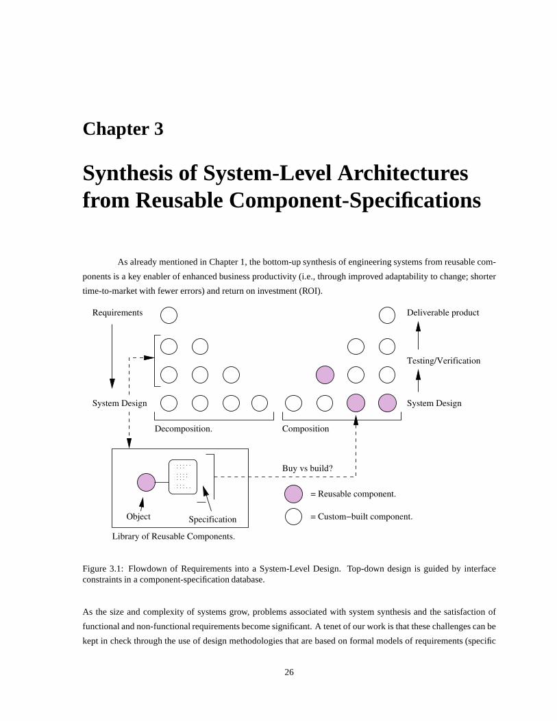
Figure 3.1: Flowdown of Requirements into a System-Level Design. Top-down design is guided by interfaceconstraints in a component-specification database.
As the size and complexity of systems grow, problems associated with system synthesis and the satisfaction of
functional and non-functional requirements become significant. A tenet of our work is that these challenges can be
kept in check through the use of design methodologies that are based on formal models of requirements (specific
26
details are covered in Chapter 2), formal models of system architectures, and automated design evaluation pro-
cedures. Computational platforms need to expose key limitations in resources and system capability (as defined
in the requirements), hide inessential details of implementation, and expose interdependencies among disciplines.
Figure 3.1 shows that as high-level requirements are decomposed into lower-level requirements, and models of
system behavior and system structure are defined, designerswould like to “look down into the product library”
to see what standards are available, and so forth. Moreover,for unaltered components to be useful across many
contexts, system architectures must be sufficiently decoupled so that they can be easily pulled apart, reconfigured,
and maintained. Every component should be open to extension, but closed to modification.
The key research question is “How do we describe reusable components and their capabilities so that
reuse actually delivers on its promise?” During the past twodecades, numerous initiatives for reuse of soft-
ware/assets have been proposed, and then they have failed [17, 44]. The causes of early failure are now evident –
organizing software/assets for reuse is hard; components/assets were too diverse in their mission; interfaces and
their behavior were poorly defined. Then in the mid 1990s, reuse initiatives gathered momentum as the need for
commercial-off-the-shelf (COTs) software/assets grew. Most recently, the drive for system/software reuse has been
motivated by new mediums of product distribution – “if it exists, then you can find it on the Web!”
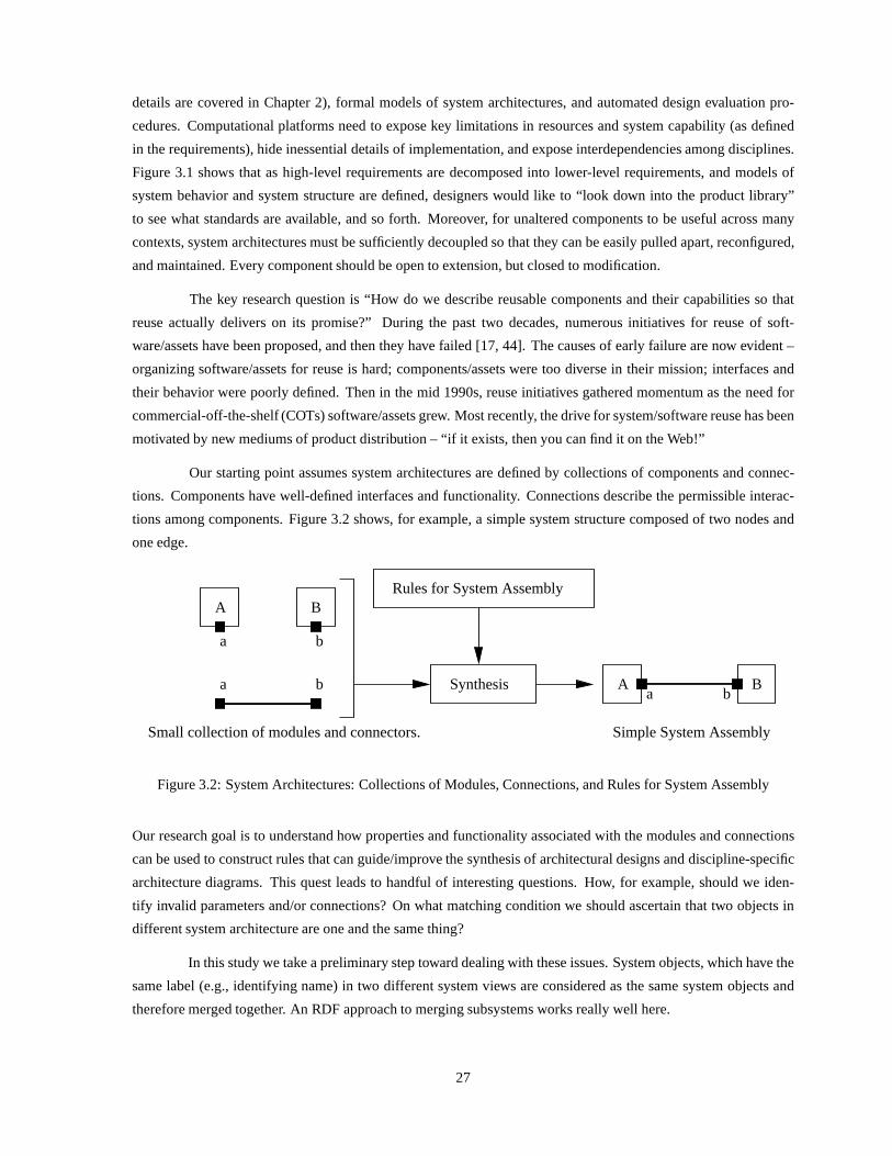
Our starting point assumes system architectures are definedby collections of components and connec-
tions. Components have well-defined interfaces and functionality. Connections describe the permissible interac-
tions among components. Figure 3.2 shows, for example, a simple system structure composed of two nodes and
one edge.
A B
a b
a b
Bba
A
Simple System AssemblySmall collection of modules and connectors.
Synthesis
Rules for System Assembly
Figure 3.2: System Architectures: Collections of Modules,Connections, and Rules for System Assembly
Our research goal is to understand how properties and functionality associated with the modules and connections
can be used to construct rules that can guide/improve the synthesis of architectural designs and discipline-specific
architecture diagrams. This quest leads to handful of interesting questions. How, for example, should we iden-
tify invalid parameters and/or connections? On what matching condition we should ascertain that two objects in
different system architecture are one and the same thing?
In this study we take a preliminary step toward dealing with these issues. System objects, which have the
same label (e.g., identifying name) in two different systemviews are considered as the same system objects and
therefore merged together. An RDF approach to merging subsystems works really well here.
27

3.1 Component- and Interface-Based Design
We define a component as an independently deliverable piece of functionality providing access to its
services through interfaces [8]. To achieve system-level application assembly from components, we need:
1. A clear separation of component specification from its design and implementation. This principle allows
for orthogonalization of design concerns (e.g., separation of models of behavior from models of system
structure).
2. An interface-based design approach.System components are defined by encapsulated behavior accessible
through well-defined interfaces. Interfaces define the services that can be provided by the component, and
the rules under which these services can be provided.
3. Formally recorded component semantics.Informal descriptions of component behavior can be provided
by way of operation signatures and informal text. However, detailed descriptions of operational semantics
require formal, verifiable descriptions using pre- and post-conditions attached to each operation.
4. A rigorously recorded refinement process.This process records the history of development for the compo-
nent, and includes information to assure quality and aspects of the designer’s rationale.
These practices are supported by the principles of orthogonalization of concerns, effective use of languages for
system modeling, and formal models for system verification.
Interface-Based Design.Interface-based design is a methodology that employs component interfaces as the key
design abstraction, separates system interfaces from the internal details of implementation for virtual components
(VCs), and shows how the interfaces at various levels of abstraction relate to each other.
Interfaces can be defined through port definitions (a port is simply a connection point into a virtual
component), interface behavior (a description of allowable activity/transactions through a port), attributes (i.e.,
data attributes; flow of control) and transactions and messages.
Pre−conditions
Post−conditions
Object
Contract
Interface
Figure 3.3: Role of Pre- and Post-Conditions in Contract forObject Usage (Source: Newton A.R., ”Notes onInterface-Based Design,” EECS, UC Berkeley)
An interface specification precisely defines what a client ofthat interface/component can expect in terms of: (1)
Supplied operations (e.g., minimum and maximum levels of component functionality); (2) Types of signal, data
28

and information flows, and (3) Operational pre- and post-conditions. Together the pre- and post-conditions and
satisfaction of the input requirements constitute a contract.
3.2 Libraries of Reusable Component-Specifications
A classical problem in the bottom up development of system architecture is identification of suitable
components in the components library. As components becomemore complex and encompasses more features,
the number and the type of specifications attached to a particular component can quickly grow – see, for example,
Figure 3.4.
In the pre-Web days component specifications were reproduced as printed media (e.g., portable document
format) and distributed through traditional mail. With theemergence of web, the same “printed media” can be
put online at supplier/vendor websites, and downloaded andprinted by the consumer. Any further processing is
still manual, mainly because the portable document format in which the component specifications are stored lack
semantic descriptions of the particular component. So it’sthe job of the systems engineer/designer to ensure that a
component meets all the requirements mapped to that particular component. Currently, specifications are matched
against requirements one by one. This can be a Herculean task. Consider, for example, a component having 20
specifications attached to it. And suppose there are 50 components from different vendors that might be suitable
for the the systems architecture. There are 20 leaf requirements mapped directly to this component, which it must
satisfy. So, in the worst case, determining the complete setof components that could be reused would require
20,000 cases to be checked. In practice, engineers often take the easy way out and make their selection from a
much smaller set (e.g., 5 instead of 50). The result will be a system design that is likely to be suboptimal.
Schema to Store the Component-Specification.If portable document format for storing the component specifi-
cation does not entail any semantics associated with it, then what form is right? With the advent of the Semantic
Web, one of the possible answers lies in the design of an XML schema specification for each component – and, of
course, specifications for components would be available for download over the Web.
In this work we propose a very simple XML schema for storing individual attributes, such as one given
below:
<Size Value="32" Units="inches" />
This attribute states that the size of a particular component is 32 inches. Java-XML parser can be written to extract
this information from specifications. More discussion and amore complete example will be illustrated in Chapter
4, where we develop the Home Theater System.
3.3 RDF-Based Storage of Object Connectivity
The Resource Description Framework (RDF) defines a standardfor specifying relationships between
objects and classes in a general and simple way. An RDF statement contains triplets viz. subject, predicate and
object. Within the semantic web layer cake, the RDF layer lies above the XML layer. It provides semantics to the
29

Input Output
Specification
Object .....
−− Cost.
Interface
−− Reliability
−− Clip Art Rendering ( .. SVG )
−− I/O Transformation ( ... ports, types ).
Graphical Abstraction
−− List of sub−system objects.
−− Class diagram ( ...UML)
Simplfied Structure
−− Production functions
−− Attributes
−− Performance
−− Finite State Machine ( .. UML)
−− Activity Diagram ( .. UML )
Simplfied Behavior
−− Postconditions ( .. rules )
−− Ports, types, ......
−− Output (specification)
−− Ports, types, ......
−− Input (requirements)
−− Preconditions ( ... rules )
Operation
Usage
Figure 3.4: Elements of Object (or Component)-Specification Pair
encoded metadata and resolves the circular references, which is an inherent problem of the hierarchical structure
of XML [24].
Generally speaking, a UML diagram drawn in the Paladin user interface consists of nodes and edges. Not
only can RDF represent these topological relationships in anatural way, but APIs exist for parsing RDF documents
and computing graph operations, such as intersection and union.
RDF Schema to Store a Node and an Edge.Let’s return to the simply system assembly shown on the right-hand
side of Figure 3.2. The RDF schema to store the connectivity properties is as follows:
<rdf:RDFxmlns:rdf=’http://www.w3.org/1999/02/22-rdf-syntax- ns#’xmlns:vcard=’http://www.w3.org/2001/vcard-rdf/3.0#’>
<rdf:Description rdf:about=’http://somewhere/A’><vcard:N>A</vcard:N><vcard:Given rdf:resource=’http://somewhere/B’/>
</rdf:Description>
<rdf:Description rdf:about=’http://somewhere/B’><vcard:N>B</vcard:N>
30

</rdf:Description></rdf:RDF>
The first block of code defines XML namespaces that are utilized by the RDF statements (namespaces take care of
name conflicts and enable shorthand notations for URIs).
xmlns:rdf=’http://www.w3.org/1999/02/22-rdf-syntax- ns#’xmlns:vcard=’http://www.w3.org/2001/vcard-rdf/3.0#’
Thexmlns:rdf namespace is the default RDF schema recommended by W3C. Thexmlns:vcard is a simple
RDF schema for properties about a person. The latter comes prepackaged with the vocabulary of the RDF API.
For simple RDF modelsvcard schema can be utilized but as the model gets more complex, oneneeds to write
his own schema and the associated RDF API for the purpose.
The second and third blocks of RDF code contain statements about two objects A and B in the system
structure. Their labels are stored throughvcard:N property, and the connection between the A and B is stored
by vcard:Given property. Again, these two choices are made among a list of available properties in the vcard
schema, which closely resembles the purpose for which it is used.
Representation of the system structure in RDF requires three triplets having the format (subject, predicate,
object) [12]:
1. (http://somewhere/A http://www.w3.org/vcard-rdf/3. 0#N "A")
2. (http://somewhere/A http://www.w3.org/vcard-rdf/3. 0#Given
http://somewhere/B)
3. (http://somewhere/B http://www.w3.org/vcard-rdf/3. 0#N "B")
The equivalent RDF graph representation is shown in Figure 3.5.
3.4 Leaf Requirements Validation Against the Component-Specification
Requirements validation is all about checking a particularrequirement to see if we are defining the
right requirement and whether it is achievable by the means of current technologies. There are two aspects to
requirements validation:
1. Formatting Concerns. By consistent format we mean that the requirement is quantifiable and has a logical
meaning. As explained earlier, current systems engineering tools do not support such a methodology. This
problem can be solved, in part, with the use of requirements templates.
2. Performance Concerns.Once the proper requirement is in place, the next question iswhether satisfaction of
the requirement can be achieved by means available processes, COTs components, and custom components.
At this time, procedures to assess “performance concerns” are largely manual. However, once suitable component-
specification library schema files have been designed, and databases have been populated, it should be a relatively
straightforward matter to write computer programs that cansystematically check requirements against the available
component specifications.
31

Figure 3.5: RDF Graph of the Data Model for a system having twonodes and one edge.
32

Chapter 4
Development of a Home Theater System
4.1 Problem Statement
Our long-term research and development objective is methodologies and tools for the combined top-down
decomposition and bottom-up synthesis and evaluation of systems that are likely to be deployed in NASA’s Global
Precipitation Measurement (NASA GPM) Project. As a first step, we are trying to understand the role Semantic
Web technologies can play in modeling requirements and system-level architectures, and develop prototype tools
that will complement present-day commercial systems engineering tools.
In this chapter, we take up the example of a home-theater system, and explore bottom-up synthesis and
evaluation processes for a problem domain familiar to the lay person. We view diagrams of system architectures
as a language, in the sense that the architecture elements (e.g., nodes, edges and attachments) are connected and
arranged under certain rules. The visualization process will be regarded as a translation (or visual mappings)
from textual languages (i.e., XML/RDF markup) into two- andthree-dimensional visual languages composed of
graphical objects, connection relationships, and geometric relationships. The generation of aesthetically pleasing
diagrams from XML/RDF markup currently lies outside the scope of work.
4.2 System Structure
The system structure of a home theater system is illustratedin Figure 4.1. The GUI portrays the essential
components assembly, completed with port and cable specification. A system object such as TV is portrayed as a
port panel consisting of several audio and video ports. Other details, such as the TV screen, are abstracted from the
system-level representation. Cables connect two ports. Inour prototype implementation, users have the freedom to
use any cable to connect a pair of ports. The equivalent XML representation for the system structure can be found
in Appendix A.
Storing Visual Properties of System Objects (XML).Every system object drawn in the graphical user interface
has visual properties like dimension, color, associated hyperlinks, ID and so forth. An XML schema, such as the
one outlined below, is proposed to store the properties of the system objects.
<?xml version="1.0" encoding="UTF-8" ?><Project>
33
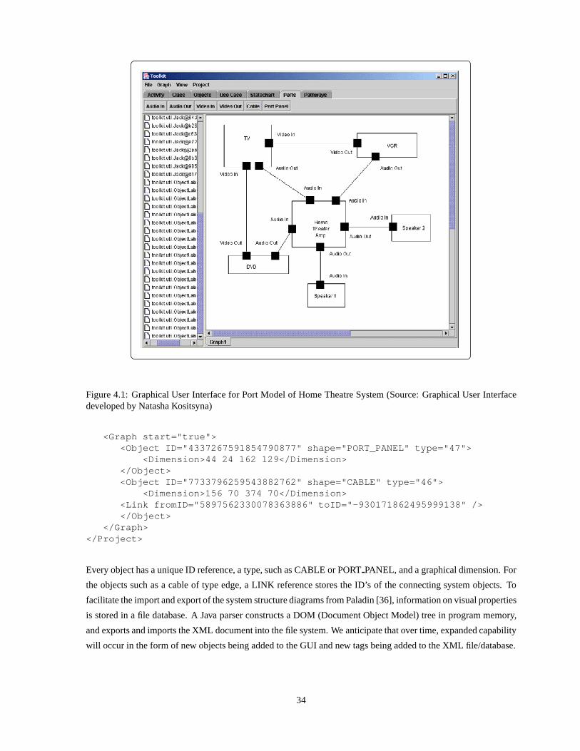
Figure 4.1: Graphical User Interface for Port Model of Home Theatre System (Source: Graphical User Interfacedeveloped by Natasha Kositsyna)
<Graph start="true"><Object ID="4337267591854790877" shape="PORT_PANEL" ty pe="47">
<Dimension>44 24 162 129</Dimension></Object><Object ID="7733796259543882762" shape="CABLE" type="4 6">
<Dimension>156 70 374 70</Dimension><Link fromID="5897562330078363886" toID="-93017186249 5999138" /></Object>
</Graph></Project>
Every object has a unique ID reference, a type, such as CABLE or PORT PANEL, and a graphical dimension. For
the objects such as a cable of type edge, a LINK reference stores the ID’s of the connecting system objects. To
facilitate the import and export of the system structure diagrams from Paladin [36], information on visual properties
is stored in a file database. A Java parser constructs a DOM (Document Object Model) tree in program memory,
and exports and imports the XML document into the file system.We anticipate that over time, expanded capability
will occur in the form of new objects being added to the GUI andnew tags being added to the XML file/database.
34

4.3 System Requirements
Even a simple system such as a home theater can have large number of requirements. For the purposes
of illustration, in this section we specify a small subset ofrequirements organized into a three-layer hierarchy, as
shown in Figure 4.2.
Figure 4.2: Requirements Document Structure
Customer needs lie at the top of the hierarchy (Level 1). Requirements become more specific as they flow down
to the next higher-levels. The decomposition of requirements continues until they can be assigned to individual
components. In practice, when this lowest level of requirements is attained, a design team is assigned responsibly
for designing the particular component to be compliant withthe low-level requirements.
Level 1 Requirements- Preliminary Agreement between Customer and Builder
REQ.1.1: I need to assemble a good home theater system from th e market.
REQ.1.2: The total cost must be less than or equal to USD 8000.
Level 2 Requirements- Detailed Agreement between customer and Builder
REQ.2.1: The home theater shall have a large display screen.
REQ.2.2: The display should be able to be mounted on the wall.
REQ.2.3: The system shall have a high fidelity audio system.
REQ.2.4: All components will be bought from the market.
REQ.2.5: Components of the systems shall be connected to eac h other.
35

As mentioned earlier, the level 2 requirements are more refined than those at level 1. Part of the refinement process
is the establishment of complying and defining requirementsrelationships. As illustrated in Figure 4.2, REQ.1.1 is
a defining requirement for all level two requirements. This is because, as a group, the level 2 requirements define
what is “good” for the customer (i.e., see REQ.2.1 thru REQ.2.3 and REQ.2.5). REQ.1.1 is also a defining require-
ment for REQ.2.4 – users want to assemble the system from electronic components available in the commercial
market (REQ.2.4). The cost requirement (REQ.1.2) is a defining requirement for REQ.2.1 thru REQ.2.3 because
a user is constrained by budget considerations, and cannot simply buy whatever is best in the market. As men-
tioned in Section 2.3, requirements can comply and define at the same level, REQ.2.1 thru REQ.2.3 are complying
requirement of REQ.2.4 because the components need to be bought from the market. For example, in the era of
mono aural audio signals, a high-fidelity system can’t mean asurround sound system because such systems were
unavailable in the market.
Level 3 Requirements- Component Requirements
REQ.3.1: Size of the TV shall be at least 32 inches.
REQ.3.2: Thickness of the TV shall not be greater than 6 inche s.
REQ.3.3: Cost of the TV shall be less than 5000 USD.
REQ.3.4: Cost of the Amplifier shall be less than 600 USD.
REQ.3.5: Output of the speaker shall lie within 200 watts and 350 watts.
REQ.3.6: The AudioOut Port of TV shall connect to AudioIn por t of Amplifier.
REQ.3.7: The AudioOut Port of VCR shall connect to AudioIn Po rt of Amplifier.
REQ.3.8: The AudioOut Port of DVD shall connect to AudioIn Po rt of Amplifier.
REQ.3.9: The VideoOut Port of VCR shall connect to VideoIn Po rt of TV.
REQ.3.10: The AudioOut Port of Amplifier shall connect to Au dioIn Port of Speakers.
Relationships among requirements at this level can be reasoned with in a similar way to those at level 2. For
example, REQ.3.6 thru REQ.3.10 are the complying interfacerequirement of REQ.2.5. A point worth noting is
that relationships between requirements are sometimes subjective – whether or not the relationship exists depends
on the perspective of the engineer designing the system. To complicate matters, these links and relationships may
change as the system design evolves.
The complete RDF representation of the three-layer requirement hierarchy can be found in Appendix-B.
4.4 Requirement Template Structure
As discussed in Section 2.4, templates provide a formal structure for representing quantifiable component-
level requirements. Figure 4.3 shows, for example, a screendump of the input process for REQ.3.1, which says
“Size of TV shall be at least 32 inches.” Notice that REQ.3.1 has template type 3. Other requirements attributes
like Name, Rationale, Description and Revision are also illustrated.
User input is translated into a requirement XML property file. For complete details, the interested reader
is referred to Appendix-C. The fragment of code:
36
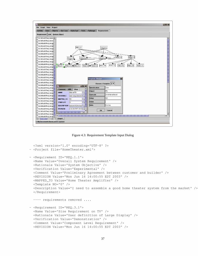
Figure 4.3: Requirement Template Input Dialog
<?xml version="1.0" encoding="UTF-8" ?>- <Project file="HomeTheater.xml">
- <Requirement ID="REQ.1.1"><Name Value="Overall System Requirement" /><Rationale Value="System Objective" /><Verification Value="Experimental" /><Comment Value="Preliminary Agreement between customer a nd builder" /><REVISION Value="Mon Jun 16 14:00:55 EDT 2003" /><MAPPED_TO Value="Home Theater Amplifier" /><Template NO="0" /><Description Value="I need to assemble a good home theater s ystem from the market" /></Requirement>
---- requirements removed ....
- <Requirement ID="REQ.3.1"><Name Value="Size Requirement on TV" /><Rationale Value="User definition of Large Display" /><Verification Value="Demonstration" /><Comment Value="Component Level Requirement" /><REVISION Value="Mon Jun 16 14:00:55 EDT 2003" />
37

Figure 4.4: Complying Requirements (1-Level) with respectto REQ.2.3
Figure 4.5: Defining Requirements (1-Level) with respect toREQ.2.3
38
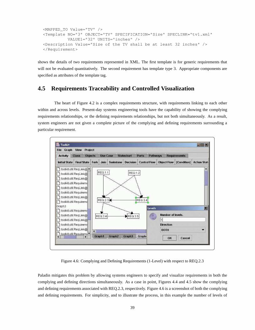
<MAPPED_TO Value="TV" /><Template NO="3" OBJECT="TV" SPECIFICATION="Size" SPECL INK="tv1.xml"
VALUE1="32" UNITS="inches" /><Description Value="Size of the TV shall be at least 32 inche s" /></Requirement>
shows the details of two requirements represented in XML. The first template is for generic requirements that
will not be evaluated quantitatively. The second requirement has template type 3. Appropriate components are
specified as attributes of the template tag.
4.5 Requirements Traceability and Controlled Visualization
The heart of Figure 4.2 is a complex requirements structure,with requirements linking to each other
within and across levels. Present-day systems engineeringtools have the capability of showing the complying
requirements relationships, or the defining requirements relationships, but not both simultaneously. As a result,
system engineers are not given a complete picture of the complying and defining requirements surrounding a
particular requirement.
Figure 4.6: Complying and Defining Requirements (1-Level) with respect to REQ.2.3
Paladin mitigates this problem by allowing systems engineers to specify and visualize requirements in both the
complying and defining directions simultaneously. As a casein point, Figures 4.4 and 4.5 show the complying
and defining requirements associated with REQ.2.3, respectively. Figure 4.6 is a screenshot of both the complying
and defining requirements. For simplicity, and to illustrate the process, in this example the number of levels of
39

traceability is set to 1 (see the traceability options dialog box). Visualization of complying/defining requirements
across multiple levels of traceability (e.g., 2, 3 and 4....) may make sense for very large graphs of requirements
organized into multiple layers.
4.6 Merging Two Requirement Trees
Requirement trees or system structure diagrams consist of nodes and edges. In team-based development,
discipline specific graphs and trees of requirements may be developed by separate groups. To obtain a complete
description of the requirements (and system architecture)these discipline specific viewpoints need to be stitched
together. Paladin supports the merging of graphs represented in an RDF format.
As a case in point, Figure 4.7 represents two hypothetical requirements hierarchies obtained from two
different sources. Now suppose that the hierarchies need tobe merged together on the basis of common objects.
The result of the merge operation is shown in Figure 4.8.
4.7 Collapsing Requirement Tree with Duplications
In Section 2.3 we specified the underlying graph structure ofrequirements, which when represented as
a tree, yields duplicate nodes, as shown in Figure 2.4. For large-scale engineering projects, the printed tree of
requirements may cover all four wall of a moderate sized room. Identifying and reasoning with duplicate nodes in
an appropriate manner may be, at best, a cumbersome and errorprone process.
A key benefit in using RDF for the representation of nodes and edges of requirements is that a collapse
operation can be performed on trees. This operation removesduplicate duplicate nodes from the tree structure,
thereby revealing the underlying requirements graph structure.
For example, Figure 4.9 shows a requirements tree containing two duplicates of REQ 2.2 and three
duplicates of REQ 3.1. Figure 4.10 shows the graph structureafter the collapsing operation. Looking ahead, we
anticipate that this functionality will be especially useful in larger project contexts, such as NASA-GPM.
4.8 Components Library
The components specifications are stored in an XML database comprising of individual components and
their associated specifications list. Component level requirements (Level 3 in this case) are checked against the
specifications to validate the usability of a particular component in the system structure.
A very simple schema for storing the specification of a particular TV is shown as below:
<?xml version="1.0" encoding="UTF-8" ?><!-- Specification of the TV --><Object Name="TV">
<Size Value="27" Unit="inches" /><Brand Value="Sony" /><Cost Value="1400" Units="USD" />
40

Figure 4.7: Two Different Requirement Hierarchies Prior toMerging Operation
41

Figure 4.8: Requirements Graph after the Merging Operation
<Type Value="Plasma" /><Mass Value="50" Unit="lbs" /><Thickness Value="5" Unit="inches" />
</Object>
This small example is by no means the complete specification.Rather, it only serves the purpose of illustrating the
schema. As outlined in the earlier, these schema files will bestored on the vendor web sites and will be downloaded
on the fly. The vendor web sites might also contain ontologiesof relevant properties and relations for the particular
problem domain. Together, the component-specification andontologies can be utilized by reasoning engines to
provide guidance and answers for requirements validation.
4.9 Low-Level Validation of Requirements
When we see the above specification file and compare this particular instance of a TV with the specified
requirements, we see that this TV clears the requirements onthe cost and thickness, but fails against the screen
size. When we invoke the toolkit command to check the requirement against the specification file, we get a dialog
similar to the following, allowing users to take either of the two actions:
1. The user can relax the requirement on the Size for the TV.
2. The user can choose another instance of the TV from the database, which might satisfy all the component level
requirements as specified above.
42

Figure 4.9: Requirements Tree Prior to Collapsing Operation
Figure 4.10: Requirements Graph After Collapsing Operation
43

Figure 4.11: Error Dialog thrown during Leaf Requirement Validation against Object Specification
44

Chapter 5
Ontology-Enabled Validation of SystemArchitectures
This chapter reports on a preliminary investigation into the application of “ontologies and reasoning” for
the validation and verification of system-level architectures. The key concern for design purposes is “how do we
ensure the system model is error (or defect) free?” And then,once a failure has been detected “how do we identify
and fix the underlying cause of the failure?” Ideally, we would like validation and verification procedures to be an
integral part of the team-based system development process, rather than a postscript to development.
Our long-term research objective is to fully understand theextent to which relationships and constraints
in ontology-based descriptions of problem domains, working together with description logic reasoning engines,
can influence and improve system-level design procedures, particularly in the early stages of development where
errors may have a significant long-term impact, but if detected early are cheap to correct. A tenet of our work is
that theories of ontologies lead to improved conceptual models – that is, they help to ensure system-level designs
are faithful representations of both the “stakeholder needs” and the capabilities of the participating application
domain(s). For this pathway of thinking to work, system-level models need to possess several attributes [49]:
1. Accuracy.The system-level model needs to accurately represent the semantics of the participating application
domains, as perceived by the project stakeholders.
2. Completeness.The system-level model should completely represent the relevant semantics of the problem
domain, as perceived by the project stakeholders.
3. Conflict-free. The semantics used in various parts of the system-level model and/or various application
domains should not contradict one another.
4. No redundancy. To reduce the likelihood of conflicts arising if and when the model is updated, the model
should not contain redundant semantics.
Because a unified theory for system validation does not existat this time, present-day procedures for system
validation/testing tend to focus on small snippets of the system model functionality, and are achieved in several
ways: (1) consistency checking, (2) connectivity analysis, and (3) model analysis on a global basis, based upon
graph-theoretic techniques. Irrespective of the approach, there are two challenges that must be addressed in the
45

Figure 5.1: Overall Schema for Ontology-Enabled Model Checking
design of suitable validation procedures. First, problem formulations need to abstract from the system-level model
all of the details not relevant to the assertions that will betested. This strategy of selective abstraction serves
the dual purpose of helping to keep the validation model computationally tractable, and, simplifying the task of
identifying faults (conflicts or incompatibilities) in thedesign. The second major challenge is design of test suites
(or sets of rules) that will have sufficient coverage to determine whether the system-level design contains faults.
As a starting point to this avenue of research, in this chapter we develop a Port-Jack ontology for the
home theater system. Class relationships and the domain restriction between the Port and Jack specify what kind
of connections are permitted. The fact base is translated toJess input, and rules are added on the basis of the
instances created in the Paladin GUI [36]. The result is a rules-based system that uses rules to reach conclusions
from a set of premises about connectivity relationships in the home theatre system.
46

5.1 Model Checking Procedure
The model checking procedure begins with the formulation ofa Port-Jack ontology that will describe
allowable constraining relationships in the port and jack connectivity. Allowable types of connections are expressed
in the form of domain restrictions. We start with an Ontologyhaving only an audio cable and the associated ports.
Figure 5.1 illustrates two parallel paths of development, namely Ontology development and its integration
with the Paladin GUI to achieve model checking. On the right-hand side, classes and the constraining relationships
in the form of domain restrictions are defined. DAMLJessKB facilitates reading DAML+OIL pages, interpreting
the information as per the DAML+OIL language, and allowing the user to reason over that domain of information
[12, 35]. The DAMLJessKB software [13, 14] employs the SPRACRDF API to read in the DAML+OIL file
as a collection of RDF triples. The RDF triples form the fact base of the Jess input file. Jess [30] is a rule
engine and scripting environment written in the Java language that can be used to write applications that have the
capacity to reason using knowledge supplied in the form of declarative rules. Jess employs the Rete algorithm
[19] to process rules, a very efficient mechanism for solvingdifficult many-to-many matching problems. On
the left-hand side of Figure 5.1, the component assembly is defined in Paladin. The Paladin GUI generates the
instances of classes defined in the ontology along with the connectivity between the ports and the jacks in form
of constraints as specified by the user. To conclude that the system architecture is consistent with the ontology
definitions/restrictions, constraints defined by the user and the ontology need to be consistent (i.e., simultaneously
true). At this point, only the right-hand side of Figure 5.1 has been fully implemented. To demonstrate that the
method will work, we simulate the rules and facts that would be generated by nodes in the GUI.
5.2 Class Relationships in Port-Jack Ontology
DAML+OIL (DARPA Agent Markup Language) and the OWL (Web Ontology Language) [59] are two
different syntaxes that one can use to create an ontology. DAML+OIL is built on the top of RDF; but it has much
richer semantics and schema than RDF.
Figure 5.2: Class Relationship in the Port-Jack Ontology
For the purposes of illustration, we consider a simple example having only one cable and associated ports, and its
definition stored in the ontology. The cable is a typical Audio cable containing two jacks, namely “Audio Out”
jack and “Audio In” jack. The corresponding ports are the “Audio Out” Ports and the “Audio In” Ports. The cable
47

definition includes information on the types of allowable port and jack connections, and what type of jacks a cable
can have at its two ends.
Figure 5.2 illustrates the corresponding class definitionsand the relations between the instances as defined
in the Ontology. The convertsto relationship signifies the fact that an audio cable has twodifferent types of audio
ports at two ends. As we will soon see, relationships of this type can be enforced through the use of rules in a logic
engine.
At this point, a few remarks on the complexity of ontology development are appropriate. The number of
blocks of DAML code needed to represent an ontology increases with the number of leaf nodes in the ontology.
The size of the DAML blocks, measured in terms of lines of code, increases with increasing numbers of constraints
among the classes. One complicating factor in the implementation is that Ontologies are not unique; indeed, an
underlying feature of the Semantic Web, which we will need tolearn how to deal with, is that the structure of
the various classes and the relationships that emerge can bestrongly influenced by the perspectives of the creator.
While one developer might think to make a certain thing an attribute of the class, another might implement the same
concept it a different class. The details of ontology implementation propagate to the details of implementation for
the rule checking procedures.
5.3 Equivalent DAML Representation of the Ontology
Once the class and various relationships are in place, we need to create an equivalent DAML representa-
tion. There are two ways to generate this transformation:
1. The DAML representation can be hard coded in a text file by writing the classes and their relationships
manually.
2. We can use graphically-driven software for ontology-basedcomputing that reads in the classes and their
relationships, and then generates the DAML or other representation as needed.
The first approach is not very intuitive, and often results inontology definitions that are not completely consistent.
Hence, we will follow the second approach here. The tool we have used for defining the Ontology is Protg [45]
developed in Stanford University with a plugin to generate the DAML file from SRI [13]. Figures 5.3 and 5.4
provide snapshots of the tool being used to define the class AudioOutJack and the slot convertsto. A slot in Protg
maps to domain restriction in DAML. For a description and examples of domain restriction, slots, and the subclass
relationship, the interested reader is referred to [14].
The Ontology created using this software can be exported in the HTML format, which can be browsed
in a web browser such as Netscape [35]. See Figure 5.5. This feature facilitates documentation of the Ontology, as
the class relationships and the properties associated withare stored in the HTML format suitable for browsing.
The DAML plugin used along with Protg generates the DAML file for the Port-Jack Ontology – the
complete details are located in Appendix D. A small snippet of the generated DAML code is as follows:
1 <daml_oil:Class rdf:ID="AudioOutJack">
48

Figure 5.3: A Screenshot of Protg GUI Illustrating Class Properties of AudioInJack
Figure 5.4: A Screenshot of Protege GUI Illustrating Slot Properties of convertsto
49

Figure 5.5: Screenshot of the Exported Ontology Documentation in HTML
2 <rdfs:subClassOf>3 <daml_oil:Restriction>4 <daml_oil:toClass rdf:resource="#AudioInJack"/>5 <daml_oil:onProperty rdf:resource="#converts_to"/>6 </daml_oil:Restriction>7 </rdfs:subClassOf>8 <rdfs:subClassOf rdf:resource="#Jack"/>9 </daml_oil:Class>
Line 1 specifies that AudioOutJack belongs to the class schema of damloil. Lines 2-7 specify that the covertsto
property of an instance of AudioOutJack should have an instance of AudioInJack as a value. Line 8 enforces the
subclass relationship between the AudioOutJack and the Jack – subclass means that an instance of AudioOutJack
is also an instance of a Jack. An equivalent graphical representation for this snippet of code, as obtained from the
W3C RDF Validation service [58] is illustrated in Figure 5.6.
Appendix D contains similar fragments of code for the classes AudioInJack, Port, AudioInPort and
AudioOutPort, and the object properties covertsto and connectsto.
5.4 Conversion of DAML Representation to Jess Facts
The Paladin graphical user interface is used to create a diagram of the system structure. Graphical
elements in the system structure diagram correspond to instances of the classes defined in the Port-Jack Ontology.
50

Figure 5.6: Equivalent RDF Graph of the Port-Jack Ontology
51

With this connection in place, the next step is to validate that a particular cable and port connection is consistent
with relationships defined in the Port-Jack Ontology. For this pathway of processing to work, we need a rule engine
such as Jess [30] to convert the Ontology definitions and relations into a series of assertions or known facts. This is
achieved by using the DAMLJessKB [12] converter developed at Drexel University. DAMLJessKB defines a set of
Java API’s and packages, which takes the DAML representation of the ontology as input. It streams the underlying
DAML model into a series of triples and converts it into Jess assertions.
The DAML representation for the Port-Jack ontology is converted into 33 Jess facts (facts are represented
as RDF triplets prefixed by the PropertyValue key), which we then assert to be true. For example, the fragment of
code:
assert((PropertyValue http://www.w3.org/1999/02/22-r df-syntax-ns#typehttp://www.isr.umd.edu/˜vmayank/SimpleOntology.daml #Porthttp://www.daml.org/2001/03/daml+oil#Class) )
asserts that Port is a class. (This fact is added to Jess’s working memory). The complete list of Jess facts may be
found in Appendix E.
5.5 Addition of Rules and Execution of Rete Algorithm
At this time, the automatic generation of instances of Port-Jack classes from the component assembly in
Paladin – why? pressures to graduate on time – has not been implemented. Hence, we will systematically generate
sample rules that would be generated from the Jess Java API, when connected to Paladin. For the Port-Jack
ontology, there are three pairs of outcome for correct/incorrect configuration:
Rule 1. This rule will be fired when the cable has correct jacks at its two ends. The output generated by this rule
is: Cable jacks are consistent with ontology definition .
Rule 2. This rule will be fired when the cable does not have correct jacks at its two ends as per the Ontology
definition. The output generated by this rule is:Cable jacks not consistent with ontology
definition .
Rule 3. This rule will be fired when Jack A is properly Connected to Port A as per the Ontology definition.
The output generated by this rule is:Jack A consistent with Port A as per ontology
definition .
Rule 4. This rule will be fired when Jack A is not properly Connected toPort A per the Ontology definition.
The error message is as follows:Jack A not consistent with Port A as per ontology
definition. If you are sure that cable is compatible with the port try reversing
the cable .
Rule 5. This rule will be fired when Jack B is properly Connected to Port B as per the Ontology definition.
The output generated by this rule is:Jack B consistent with Port B as per ontology
definition .
52

Rule 6. This rule will be fired when Jack B is not properly Connected toPort B as per the Ontology definition.
The error message is as follows:Jack B not consistent with Port B as per ontology
definition. If you are sure that cable is compatible with the port try reversing
the cable .
When the implementation is complete, Jack and Port instances will be generated programmatically from the GUI
as per the user input and fed into this defrule construct of Jess. Execution of the Rete algorithm will result in an
assertion that the provided set of facts (generated from thecable configurations) are consistent with the ontology
definitions. An error message will be printed for each inconsistency in the design, thereby providing the designer
with a means to bridge the gap between designer intent and a manufacturer’s specification for system/object usage.
Suppose, for example, that instances of Jack A and Jack B havebeen generated programmatically (i.e.,
without the direct role of Paladin). The Jess implementation of Rule 1 is as follows:
(defrule allowed-jack-config(PropertyValuehttp://www.daml.org/2001/03/daml+oil#toClass?anonhttp://www.isr.umd.edu/˜vmayank/SimpleOntology.daml #AudioOutJack)
(PropertyValuehttp://www.daml.org/2001/03/daml+oil#onProperty?anonhttp://www.isr.umd.edu/˜vmayank/SimpleOntology.daml #converts_to)
(PropertyValuehttp://www.w3.org/2000/01/rdf-schema#subClassOfhttp://www.isr.umd.edu/˜vmayank/SimpleOntology.daml #AudioInJack?anon)
(PropertyValuehttp://www.w3.org/1999/02/22-rdf-syntax-ns#type?anonhttp://www.daml.org/2001/03/daml+oil#Restriction)=>(printout t "Cable jacks are consistent with ontology defin ition" crlf)
) ;; end defrule construct
The variablesAudioOutJack andAudioInJack in facts 1 and 3 correspond to the types of Jack A and Jack
B, respectively. The reasoning procedure works as follows:if triplets 1 through 4 are present in the Jess fact base,
then this rule will be fired and output generated.
53

Chapter 6
Conclusions and Future Work
6.1 Conclusions
Driven by economic and time-to-market concerns, the development of large and complex multi-disciplinary
systems is moving a toward a bottom-up development paradigm. With vendors specializing in particular products,
this approach emphasizes reuse of product and outsourcing wherever possible. In this study we have employed
RDF and XML technologies to create a computing infrastructure that can query the system database and analyze
the connectivity relationships among system objects. We have taken some preliminary steps toward the use of
graph operations that can answer problems associated with controlled visualization of requirements and discipline
specific system viewpoints. Finally, a primitive step has been taken toward the assessment of ontology-based
computing for validation of properties in a systems architecture.
Looking ahead, we see overall system development as a confluence of top-down and bottom-up strategies,
organized for team-based activities, and revamped to take advantage of Semantic Web and agent technologies. An
agent-based approach to computing offers the promise of enabling distributed system development processes that
are more scalable, flexible, extensible and interoperable than state-of-the-art procedures today. We anticipate
that when production-level systems of the type described inChapters 4 and 5 are common place, content for the
right hand side of Figure 5.1 will come from manufacturers who will make ontologies for their product lines
available for download over the Web. Ontologies will contain specifications for system/object usage (represented
as propositions in a finite logic). At the time of system architecture validation, these ontologies will be downloaded
and imported into system-level design environments. Appropriate logic calculations (theorem provers) will reveal
inconsistencies between the intent of designers and manufacturers and features of the actual system design.
6.2 Future Work
This work opens up a whole new domain of opportunities for newmethodologies and tools for systems
engineering. The related research issues include:
1. AP233 [42, 43] is an emerging standard for systems engineering data exchange among vendor tools such
as SLATE, DOORS, Rational Requisite PRO, and CORE [1, 10, 15]. Once AP233 is fully developed and
adapted by various vendors, it is our plan to update our XML encoding for requirements representation and
54

traceability so that it is AP233 compliant. Then, we will be able to import data from other tools and represent
and manipulate it in our GUI.
2. In this project we have used RDF and XML to formulate an information representation for graphs of require-
ments. The scope of our work has been restricted to requirements that follow a fixed storage format. It
is clear, however, that in team-based development, requirements will emanate from multiple sources and
be very heterogeneous, in terms of storage format, organization. Hence, there is a need for research and
development that will advance the ability of various document types to be annotated with RDF descriptions
of their semantic content. This capability will create a pathway toward elicitation, representation, synthesis,
and management of heterogeneous requirement types.
3. As the Semantic Web drives the storage of component specifications onto web, there will be a pressing need
for a specification builder GUI that will elicit the necessary data, and export it to a standardized component
specification schema formulated and agreed upon by the product vendors.
4. We have demonstrated in this work that a simple Jack and Port ontology can enable the analysis of connec-
tivity relationships in a system architecture. Ideally, wewould like to extend this capability to families of
ontologies who, collectively, provide complete coverage of concepts relating to the system capability and
system development process. Reasoning procedures should be capable of working at the level of individual
sub-systems/modules and across collections of heterogeneous entities.
One assumption that makes the Jack-Port ontology example unrealistically simple is hard coding of the
design activity (i.e., Port and Jack connectivity) contextinto the Jess rule base. In our opinion, future imple-
mentations should move toward a capability for context-aware computing; that is, a computing environment
that employs knowledge and reasoning to understand the local context – concepts, relationships and attributes
– of design situations, and then shares and reasons with information to and from other system types.
It seems that context-aware computing can be implemented asa set of progressively complex layers. First,
simplified notions of context can be attached to objects (e.g., jacks and ports). A much more challenging
problem is determination of appropriate context, with appropriation and reasoning) in the assembly of the
system structure. Such an environment would make use of application- and context-specific ontologies
covering various types of design spaces (e.g., port-model design; electro-mechanical spacecraft design).
5. After the requirements are elicited (correctly) from the use cases and scenarios, the next major step is to gen-
erate and evaluate system architecture alternatives and conduct trade-off and optimization studies. A limited
capability for importing various components manually fromthe components library is already in place.
There is a strong need for frameworks that will allow the userto analyze an entire database of components,
and provide the designer with the critical feedback on the design margins based on the imported components
specification. These framework should be integrated with the optimization tools, such as CPLEX, thereby
allowing users to generate and graphically display families of noninferior design solutions and/or tradeoff
surfaces among performance attributes.
6. Our present work is based solely on the representation of requirements, system structure and mapping between
them. Still missing is a framework for building and exporting the system behavior diagram (such as state
55

charts, functional flow block diagram) along with associated semantics. This tool might also be integrated
with simulation tools such as Arena and finite state automatato carry out simulations and verification of the
system.
7. Validation procedures should also be extended so that they can handle a complete range of connectivity
concerns enabled by the port model in Chapter 4. In Chapter 5,we have validated connectivity based on
labels alone. A useful extension of capability would be toward validation of physical flows – signals, forces,
energy – where compatibility of physical units is a prerequisite to connectivity.
8. Last but not the least, visualization of systems architecture needs to be polished, as the diagrams should look
aesthetically pleasant. An integration of graph drawing algorithms [16, 25, 53] with possibly import of
packages from existing sources [28, 31, 57] could be integrated into the tool to provide the automatic graph
layout as per the specified algorithm
56
Bibliography
[1] SLATE. See http://www.eds.com/products/plm/teamcenter/slate/. 2003.
[2] Adobe Illustrator. See http://www.adobe.com/products/illustrator/main.html. 2002.
[3] ARENA Simulation. See http://www.arenasimulation.com/. 2003.
[4] Baader F., Calvanese D., McGuinness D., Nardi D., Patel-Schneider P.The Description Logic Handbook.
Cambridge University Press, February 2003.
[5] Berners-Lee, T. XML and the Web. Keynote address at the XML World 2000 Conference.
[6] Berners-Lee T., Hendler J., Lassa O. The Semantic Web.Scientific American, pages 35–43, May 2001.
[7] Bray T., Paoli J., Sperger-McQueen S., editors.. Extensible Markup Language (XML) 1.0, W3C Recommen-
dation, February 1998. See http://www.w3.org/TR/REC-xml.
[8] Brown A.W. Large-Scale Component-Based Development. Addison-Wesley, 2000.
[9] Ciocoiu M., Gruninger M., Nau D.S. Ontologies for Integrating Engineering Applications.Journal of Com-
puting and Information Science in Engineering, 1(1):12–22, 2001.
[10] CORE. See http://www.vitechcorp.com/productline.html. 2003.
[11] DARPA Agent Markup Language (DAML). See http://www.daml.org. 2003.
[12] DAMLJessKB. See http://edge.mcs.drexel.edu/assemblies/software/damljesskb/damljesskb.html. 2003.
[13] DAML+OIL Plugin for Protg 2000. See http://www.ai.sri.com/daml/DAML+OIL-plugin/index.htm. 2003.
[14] DAML+OIL Walk Through. See http://www.daml.org/2001/03/daml+oil-walkthru.html. 2003.
[15] Dynamic Object Oriented Requirements System (DOORS).See http://www.telelogic.com/products/doorsers/doors/.
2003.
[16] Eades P, Tamassia R. Algorithms for Drawing Graphs: An Annotated Bibliography. Technical Report
Technical Report CS-89-09, Department of Computer Science, Brown University, Providence, R.I., February
1989.
[17] Easili V., and McGarry F. et al. The Software Engineering Laboratory – An Operational Experience Factory.
In Proceedings of the Fourteenth International Conference onSoftware Engineering, Melbourne, Australia,
May 1992.
57

[18] Fensel D., van Harmelen F., Horrocks I., McGuinness D.,Patel-Schneider P. OIL: An Ontology Infrastructure
for the Semantic Web.IEEE Intelligent Systems, pages 38–45, March/April 2001.
[19] Forgy C.L. Rete: A Fast Algorithm for the Many Pattern/Many Object Pattern Match Problem.Artificial
Intelligence, 19:17–37, 1982.
[20] Geroimenko V., and Chen C. (Eds).Visualizing the Semantic Web: XML-based Internet and Information
Visualization. Springer, 2003.
[21] Golbeck J., Grove M., Parsia B., Kalyanpur A., and Hendler J. New Tools for the Semantic Web. InProceed-
ings of 13th International Conference on Knowledge Engineering and Knowledge Management EKAW02,
Siguenza, Spain, October 2002.
[22] Global Precipitation Measurement Project. See http://gpm.gsfc.nasa.gov/index.html. 2003.
[23] Gruniger M., and Lee J. Ontology Applications and Design. Communications of the ACM, 45(2):39–41,
February 2002.
[24] Hendler J. Agents and the Semantic Web.IEEE Intelligent Systems, pages 30–37, March/April 2001. Avail-
able on April 4, 2002 from http://www.computer.org/intelligent.
[25] Herman I. Graph Visualization and Navigation in Information Visualization: A Survey.IEEE Transactions
on Visualization and Computer Graphics, 6(1):24–43, January-March 2000.
[26] Hull M.E.C., Jackson K., and Dick A.J.J.Requirements Engineering, Practitioner Series. Springer, New
York, USA, 2002.
[27] ILOG CPLEX. See http://www.cplex.com. 2003.
[28] ILOG Views Component Suite. See http://www.ilog.com/products/views/graphlayout/. 2003.
[29] Jena - A Java API for RDF. See http://www.hpl.hp.com/semweb/. 2003.
[30] Jess – The Expert System Shell for the Java Platform. Seehttp://herzberg.ca.sandia.gov/jess/. 2003.
[31] Jgraph. See http://jgraph.sourceforge.net. 2003.
[32] Kalyanpur A., Golbeck J., Grove M., and Hendler J. An RDFEditor and Portal for the Semantic Web. July
2002.
[33] Kalyanpur A., Parsia B., Hendler J., Golbeck J. SMORE - Semantic Markup, Ontology, and RDF Editor,
2003. Maryland Information and Network Dynamics (MIND) Lab, University of Maryland, College Park.
For details, see http://www.mindswap.org.
[34] Kiliccote H., Garrett J.H. Standards Usage Language (SUL). Journal of Computing in Civil Engineering,
15(2):118–128, 2001.
[35] Kopena J., and Regli W.C. DAMLJessKB: A Tool for Reasoning with the Semantic Web.IEEE Intelligent
Systems, 2003.
58

[36] Kositsyna N., Mayank V., and Austin M. Paladin SoftwareToolset.Institute for Systems Research, 2003. For
more information, see http://www.isr.umd.edu/paladin/.
[37] Kronlof K. Method Integration : Concepts and Case Studies. John-Wiley and Sons, 1993.
[38] Lu S., Dong M., and Fotouhi, F. The Semantic Web: Opportunities and Challenges for Next-Generation Web
Applications.Information Research, 7(4), 2002. Available at: http://InformationR.net/ir/7-4/paper134.html.
[39] Maedche A.Ontology Learning for the Semantic Web. Kluwer Academic Publishers, 2002.
[40] 2002. MathML. Referenced on April 6, 2002. See hhttp://www.w3.org/Math.
[41] 2002. Matlab. Referenced on April 5, 2002. http://www.mathworks.com.
[42] Muller D. Requirements Engineering Knowledge Management based on STEP AP233. 2003.
[43] Oliver D. AP233 - INCOSE Status Report.INCOSE INSIGHT, 5(3), October 2002.
[44] Paulk M., Curtis M., Chrissis M., and Weber C. Capability Maturity Model for Software: Version 1.1.
Technical report, Pittsburgh, PA, February 1993.
[45] The Protg Ontology Editor and Knowledge Acquisition System. See http://protege.stanford.edu. 2003.
[46] RDF Data Query Language (RDQL). See http://www.hpl.hp.com/semweb/rdql.htm. 2003.
[47] Rational Rose. See http://www.rational.com/products/rose/. 2003.
[48] Selberg S. A., Austin M.A. Requirements Engineering and the Semantic Web.ISR Technical Report 2003-20,
2003. See http://techreports.isr.umd.edu/TechReports/ISR/2003/TR2003-20/TR2003-20.phtml.
[49] Shanks G., Tansley E., Weber R. Using Ontology to Validate Conceptual Models.Communications of the
ACM, 46(10):85–89, 2003.
[50] Sirin E., Hendler J., Parsia B. Semi-automatic Composition of Web Services using Semantic Descriptions,
2002. Accepted to ”Web Services: Modeling, Architecture and Infrastructure” Workshop in conjunction with
ICEIS2003.
[51] 2002. Scalar Vector Graphics (SVG). Referenced on April 5, 2002. See
http://www.w3.org/Graphics/SVG/Overview.html.
[52] Swartz A., and Hendler J. The Semantic Web: A Network of Content for the Digital City, 2002. Available at
http://blogspace.com/rdf/SwartzHendler.
[53] Tamassaia R., Battista G., and Batini C. Automatic Graph Drawing and Readability of Diagrams.IEEE
Transactions on Systems, Machines and Cybernetics, pages 61–79, January 1988.
[54] Unified Modeling Language (UML). See http://www.omg.org/uml. 2003.
[55] Unicode. Referenced on April 4, 2002. See http://www.unicode.org. 2002.
[56] URI. Referenced on April 4, 2002. See http://www.isi.edu/in-notes/rfc239c.txt. 2002.
59

[57] Drawing Graphs with VGJ. Department of Computer Science and Software Engineering, 2003. See
http://www.eng.auburn.edu/department/cse/research/graphdrawing/graphdrawing.html.
[58] W3C RDF Validation Service. See http://www.w3.org/RDF/Validator. 2003.
[59] Web Ontology Language (OWL). See http://www.w3.org/TR/owl-ref/. 2003.
[60] Microsoft Word, Referenced on April 5, 2002. See http://www.microsoft.com/office/word. 2002.
[61] Xerces. Referenced on April 4, 2002. See http://xml.apache.org. 2002.
[62] XHTML. Referenced on April 5, 2002. See http://www.w3.org/MarkUp. 2002.
[63] XSLT. Referenced on April 5, 2002. See http://www.w3.org/Style/XSL. 2002.
60
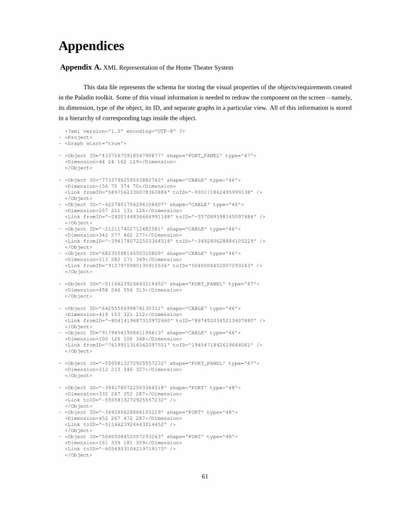
Appendices
Appendix A. XML Representation of the Home Theater System
This data file represents the schema for storing the visual properties of the objects/requirements created
in the Paladin toolkit. Some of this visual information is needed to redraw the component on the screen – namely,
its dimension, type of the object, its ID, and separate graphs in a particular view. All of this information is stored
in a hierarchy of corresponding tags inside the object.
<?xml version="1.0" encoding="UTF-8" ?>- <Project>- <Graph start="true">
- <Object ID="4337267591854790877" shape="PORT_PANEL" t ype="47"><Dimension>44 24 162 129</Dimension></Object>
- <Object ID="7733796259543882762" shape="CABLE" type=" 46"><Dimension>156 70 374 70</Dimension><Link fromID="5897562330078363886" toID="-93017186249 5999138" /></Object>
- <Object ID="-4227801706294106407" shape="CABLE" type= "46"><Dimension>257 211 131 126</Dimension><Link fromID="-2400144836664991188" toID="-3570893981 45097484" /></Object>
- <Object ID="-212117402712482581" shape="CABLE" type=" 46"><Dimension>342 277 462 277</Dimension><Link fromID="-3941780722503364518" toID="-3492806288 84105229" /></Object>
- <Object ID="6823559814550310809" shape="CABLE" type=" 46"><Dimension>213 282 171 349</Dimension><Link fromID="9127970985135915536" toID="504050845200 7293263" /></Object>
- <Object ID="-5116623924643214452" shape="PORT_PANEL" type="47"><Dimension>458 246 556 313</Dimension></Object>
- <Object ID="6425550699874130311" shape="CABLE" type=" 46"><Dimension>419 103 321 212</Dimension><Link fromID="-8041419687310972460" toID="86745203452 13607480" /></Object>
- <Object ID="9179454190841196613" shape="CABLE" type=" 46"><Dimension>100 126 100 348</Dimension><Link fromID="7619911316542097551" toID="194547184261 9664061" /></Object>
- <Object ID="-5505813272925557232" shape="PORT_PANEL" type="47"><Dimension>212 213 346 327</Dimension></Object>
- <Object ID="-3941780722503364518" shape="PORT" type=" 48"><Dimension>332 267 352 287</Dimension><Link toID="-5505813272925557232" /></Object>
- <Object ID="-349280628884105229" shape="PORT" type="4 8"><Dimension>452 267 472 287</Dimension><Link toID="-5116623924643214452" /></Object>
- <Object ID="5040508452007293263" shape="PORT" type="4 8"><Dimension>161 339 181 359</Dimension><Link toID="-6056953104219719173" /></Object>
61

- <Object ID="9127970985135915536" shape="PORT" type="4 8"><Dimension>203 272 223 292</Dimension><Link toID="-5505813272925557232" /></Object>
- <Object ID="-8631530153037221977" shape="PORT" type=" 48"><Dimension>272 317 292 337</Dimension><Link toID="-5505813272925557232" /></Object>
- <Object ID="1945471842619664061" shape="PORT" type="4 8"><Dimension>90 338 110 358</Dimension><Link toID="-6056953104219719173" /></Object>
- <Object ID="-930171862495999138" shape="PORT" type="4 8"><Dimension>364 60 384 80</Dimension><Link toID="-6397728818364024033" /></Object>
- <Object ID="-8041419687310972460" shape="PORT" type=" 48"><Dimension>409 93 429 113</Dimension><Link toID="-6397728818364024033" /></Object>
- <Object ID="-2400144836664991188" shape="PORT" type=" 48"><Dimension>247 201 267 221</Dimension><Link toID="-5505813272925557232" /></Object>
- <Object ID="8674520345213607480" shape="PORT" type="4 8"><Dimension>311 202 331 222</Dimension><Link toID="-5505813272925557232" /></Object>
- <Object ID="-357089398145097484" shape="PORT" type="4 8"><Dimension>121 116 141 136</Dimension><Link toID="4337267591854790877" /></Object>
- <Object ID="7619911316542097551" shape="PORT" type="4 8"><Text>A</Text><Dimension>90 116 110 136</Dimension><Link toID="4337267591854790877" /></Object>
- <Object ID="5897562330078363886" shape="PORT" type="4 8"><Dimension>146 60 166 80</Dimension><Link toID="4337267591854790877" /></Object>
- <Object ID="5888226028590857221" shape="LABEL" type=" 40"><Text>TV</Text><Dimension>91 46 111 68</Dimension><Link toID="4337267591854790877" /></Object>
- <Object ID="-3464995602672494238" shape="LABEL" type= "40"><Text>Home<nl>Theater<nl>Amp</Text><Dimension>260 254 308 308</Dimension><Link toID="-5505813272925557232" /></Object>
- <Object ID="5766306240200143317" shape="LABEL" type=" 40"><Text>DVD</Text><Dimension>97 364 128 386</Dimension><Link toID="-6056953104219719173" /></Object>
- <Object ID="-1125144154021993343" shape="LABEL" type= "40"><Text>Speaker 2</Text><Dimension>482 268 544 290</Dimension><Link toID="-5116623924643214452" /></Object>
- <Object ID="-2548812202442281956" shape="LABEL" type= "40"><Text>Audio Out</Text><Dimension>352 289 411 311</Dimension><Link toID="-3941780722503364518" /></Object>
- <Object ID="-8080414068675241044" shape="LABEL" type= "40">
62

<Text>Audio In</Text><Dimension>404 242 454 264</Dimension><Link toID="-349280628884105229" /></Object>
- <Object ID="5307719630104561260" shape="LABEL" type=" 40"><Text>Speaker 1</Text><Dimension>264 436 326 458</Dimension><Link toID="-7075534318685230158" /></Object>
- <Object ID="-7072323418332330746" shape="LABEL" type= "40"><Text>Video In</Text><Dimension>32 135 82 157</Dimension><Link toID="7619911316542097551" /></Object>
- <Object ID="1702425072755131235" shape="LABEL" type=" 40"><Text>Audio In</Text><Dimension>157 247 207 269</Dimension><Link toID="9127970985135915536" /></Object>
- <Object ID="-8447650783263509459" shape="LABEL" type= "40"><Text>Audio Out</Text><Dimension>170 120 229 142</Dimension><Link toID="-357089398145097484" /></Object>
- <Object ID="-566334250751855220" shape="CABLE" type=" 46"><Dimension>282 327 282 420</Dimension><Link fromID="-8631530153037221977" toID="-8831546525 121722840" /></Object>
- <Object ID="-8831546525121722840" shape="PORT" type=" 48"><Dimension>272 410 292 430</Dimension><Link toID="-7075534318685230158" /></Object>
- <Object ID="-6397728818364024033" shape="PORT_PANEL" type="47"><Dimension>373 45 522 105</Dimension></Object>
- <Object ID="-6056953104219719173" shape="PORT_PANEL" type="47"><Dimension>55 347 205 393</Dimension></Object>
- <Object ID="-3960374134036905440" shape="LABEL" type= "40"><Text>Audio Out</Text><Dimension>120 305 179 327</Dimension><Link toID="5040508452007293263" /></Object>
- <Object ID="4268930084446139984" shape="LABEL" type=" 40"><Text>Video Out</Text><Dimension>32 305 91 327</Dimension><Link toID="1945471842619664061" /></Object>
- <Object ID="7722487328336319391" shape="LABEL" type=" 40"><Text>Audio In</Text><Dimension>239 169 289 191</Dimension><Link toID="-2400144836664991188" /></Object>
- <Object ID="-4131231084681303988" shape="LABEL" type= "40"><Text>Video In</Text><Dimension>173 37 223 59</Dimension><Link toID="5897562330078363886" /></Object>
- <Object ID="-8708940313658193746" shape="LABEL" type= "40"><Text>Video Out</Text><Dimension>305 81 364 103</Dimension><Link toID="-930171862495999138" /></Object>
- <Object ID="-1380059460790430106" shape="LABEL" type= "40">
63

<Text>Audio In</Text><Dimension>350 200 400 222</Dimension><Link toID="8674520345213607480" /></Object>
- <Object ID="600277411624340355" shape="LABEL" type="4 0"><Text>VCR</Text><Dimension>445 65 476 87</Dimension><Link toID="-6397728818364024033" /></Object>
- <Object ID="-5640294704235571447" shape="LABEL" type= "40"><Text>Audio Out</Text><Dimension>428 120 487 142</Dimension><Link toID="-8041419687310972460" /></Object>
- <Object ID="-7075534318685230158" shape="PORT_PANEL" type="47"><Dimension>251 417 344 476</Dimension></Object>
- <Object ID="2386762432953440281" shape="LABEL" type=" 40"><Text>Audio Out</Text><Dimension>302 332 361 354</Dimension><Link toID="-8631530153037221977" /></Object>
- <Object ID="648612592363060694" shape="LABEL" type="4 0"><Text>Audio In</Text><Dimension>302 386 352 408</Dimension><Link toID="-8831546525121722840" /></Object></Graph></Project>
Appendix B. RDF Representation of the Requirements Structure
This data file outlines a schema to store the connectivity information of the requirement objects created
in the Paladin toolkit in the RDF. All requirements correspond to a resource, which have their ID’s as the Name
attribute, and connectivity to other requirement objects are specified through the VCARD:Given property.
<rdf:RDFxmlns:rdf=’http://www.w3.org/1999/02/22-rdf-syntax- ns#’xmlns:vcard=’http://www.w3.org/2001/vcard-rdf/3.0#’
>
<rdf:Description rdf:about=’http://somewhere/REQ.3.1 ’><vcard:N>REQ.3.1</vcard:N>
</rdf:Description>
<rdf:Description rdf:about=’http://somewhere/REQ.3.5 ’><vcard:N>REQ.3.5</vcard:N>
</rdf:Description>
<rdf:Description rdf:about=’http://somewhere/REQ.3.9 ’><vcard:N>REQ.3.9</vcard:N>
</rdf:Description>
<rdf:Description rdf:about=’http://somewhere/REQ.2.5 ’><vcard:N>REQ.2.5</vcard:N><vcard:Given rdf:resource=’http://somewhere/REQ.3.6’ /><vcard:Given rdf:resource=’http://somewhere/REQ.3.7’ /><vcard:Given rdf:resource=’http://somewhere/REQ.3.8’ /><vcard:Given rdf:resource=’http://somewhere/REQ.3.9’ /><vcard:Given rdf:resource=’http://somewhere/REQ.3.10 ’/>
</rdf:Description>
<rdf:Description rdf:about=’http://somewhere/REQ.3.6 ’>
64
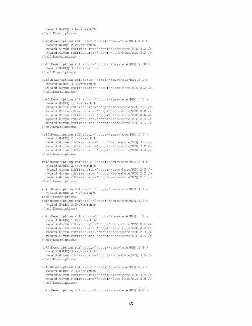
<vcard:N>REQ.3.6</vcard:N></rdf:Description>
<rdf:Description rdf:about=’http://somewhere/REQ.2.2 ’><vcard:N>REQ.2.2</vcard:N><vcard:Given rdf:resource=’http://somewhere/REQ.3.2’ /><vcard:Given rdf:resource=’http://somewhere/REQ.3.3’ />
</rdf:Description>
<rdf:Description rdf:about=’http://somewhere/REQ.3.1 0’><vcard:N>REQ.3.10</vcard:N>
</rdf:Description>
<rdf:Description rdf:about=’http://somewhere/REQ.3.3 ’><vcard:N>REQ.3.3</vcard:N><vcard:Given rdf:resource=’http://somewhere/REQ.3.2’ />
</rdf:Description>
<rdf:Description rdf:about=’http://somewhere/REQ.1.1 ’><vcard:N>REQ.1.1</vcard:N><vcard:Given rdf:resource=’http://somewhere/REQ.2.1’ /><vcard:Given rdf:resource=’http://somewhere/REQ.2.2’ /><vcard:Given rdf:resource=’http://somewhere/REQ.2.5’ /><vcard:Given rdf:resource=’http://somewhere/REQ.2.3’ /><vcard:Given rdf:resource=’http://somewhere/REQ.2.4’ />
</rdf:Description>
<rdf:Description rdf:about=’http://somewhere/REQ.2.1 ’><vcard:N>REQ.2.1</vcard:N><vcard:Given rdf:resource=’http://somewhere/REQ.3.1’ /><vcard:Given rdf:resource=’http://somewhere/REQ.3.2’ /><vcard:Given rdf:resource=’http://somewhere/REQ.3.3’ />
</rdf:Description>
<rdf:Description rdf:about=’http://somewhere/REQ.2.4 ’><vcard:N>REQ.2.4</vcard:N><vcard:Given rdf:resource=’http://somewhere/REQ.2.3’ /><vcard:Given rdf:resource=’http://somewhere/REQ.2.2’ /><vcard:Given rdf:resource=’http://somewhere/REQ.2.1’ />
</rdf:Description>
<rdf:Description rdf:about=’http://somewhere/REQ.3.7 ’><vcard:N>REQ.3.7</vcard:N>
</rdf:Description><rdf:Description rdf:about=’http://somewhere/REQ.3.2 ’>
<vcard:N>REQ.3.2</vcard:N></rdf:Description>
<rdf:Description rdf:about=’http://somewhere/REQ.1.2 ’><vcard:N>REQ.1.2</vcard:N><vcard:Given rdf:resource=’http://somewhere/REQ.2.1’ /><vcard:Given rdf:resource=’http://somewhere/REQ.2.2’ /><vcard:Given rdf:resource=’http://somewhere/REQ.2.3’ /><vcard:Given rdf:resource=’http://somewhere/REQ.2.4’ />
</rdf:Description>
<rdf:Description rdf:about=’http://somewhere/REQ.3.4 ’><vcard:N>REQ.3.4</vcard:N><vcard:Given rdf:resource=’http://somewhere/REQ.3.5’ />
</rdf:Description>
<rdf:Description rdf:about=’http://somewhere/REQ.2.3 ’><vcard:N>REQ.2.3</vcard:N><vcard:Given rdf:resource=’http://somewhere/REQ.3.4’ /><vcard:Given rdf:resource=’http://somewhere/REQ.3.5’ />
</rdf:Description>
<rdf:Description rdf:about=’http://somewhere/REQ.3.8 ’>
65

<vcard:N>REQ.3.8</vcard:N></rdf:Description>
</rdf:RDF>
Appendix C. Reqpuirements Property XML File
The following XML schema stores the properties of the individual requirements.
<?xml version="1.0" encoding="UTF-8" ?>- <Project file="HomeTheater.xml">
- <Requirement ID="REQ.1.1"><Name Value="Overall System Requirement" /><Rationale Value="System Objective" /><Verification Value="Experimental" /><Comment Value="Preliminary Agreement between customer a nd builder" /><REVISION Value="Mon Jun 16 14:00:55 EDT 2003" /><MAPPED_TO Value="Home Theater Amplifier" /><Template NO="0" /><Description Value="I need to assemble a good home theater s ystem from the market" /></Requirement>
- <Requirement ID="REQ.1.2"><Name Value="Overall Cost Requirement" /><Rationale Value="Cost limit to be imposed on the component s" /><Verification Value="Analytical" /><Comment Value="Preliminary agreement between customer a nd builder" /><REVISION Value="Mon Jun 16 14:00:55 EDT 2003" /><MAPPED_TO Value="Home Theater Amplifier" /><Template NO="0" /><Description Value="The total cost must be less than or equa l to 8000 USD" /></Requirement>
- <Requirement ID="REQ.2.1"><Name Value="Display Requirement" /><Rationale Value="Need to watch movies on large screen" /><Verification Value="Demonstration" /><Comment Value="Detailed agreement beween the customer an d builder" /><REVISION Value="Mon Jun 16 14:00:55 EDT 2003" /><MAPPED_TO Value="TV" /><Template NO="0" /><Description Value="The Home Theater shall have a large dis play screen" /></Requirement>
- <Requirement ID="REQ.2.2"><Name Value="Wall mountability" /><Rationale Value="Space saving need" /><Verification Value="Experimental" /><Comment Value="Detailed agreement between the cutomer an d builder" /><REVISION Value="Mon Jun 16 14:00:55 EDT 2003" /><MAPPED_TO Value="TV" /><Template NO="0" /><Description Value="The display should be able to be mounte d on the wall" /></Requirement>
- <Requirement ID="REQ.2.3"><Name Value="High fidelity sound" /><Rationale Value="Theater experience needs surround soun d capabilities" /><Verification Value="Demonstration" /><Comment Value="Detailed agreement between the customer a nd the builder" /><REVISION Value="Mon Jun 16 14:00:55 EDT 2003" /><MAPPED_TO Value="Speaker" /><Template NO="0" /><Description Value="The system shall have a high fidelity a udio system" /></Requirement>
66

- <Requirement ID="REQ.2.4"><Name Value="COTS Requirement" /><Rationale Value="User should be able to go to market and buy components" /><Verification Value="Experimental" /><Comment Value="Detailed agreement between the customer a nd the builder" /><REVISION Value="Mon Jun 16 14:00:55 EDT 2003" /><MAPPED_TO Value="Home Theater Amplifier" /><Template NO="0" /><Description Value="All components will be bought from the market" /></Requirement>
- <Requirement ID="REQ.2.5"><Name Value="Connectivity Requirement" /><Rationale Value="If user buys something from the market he should be
able to connect things together" /><Verification Value="Demonstration" /><Comment Value="Detailed agreement between the customer a nd the builder" /><REVISION Value="Mon Jun 16 14:00:55 EDT 2003" /><MAPPED_TO Value="Home Theater Amplifier" /><Template NO="0" /><Description Value="Components of the system shall be conn ected to each other" /></Requirement>
- <Requirement ID="REQ.3.1"><Name Value="Size Requirement on TV" /><Rationale Value="User definition of Large Display" /><Verification Value="Demonstration" /><Comment Value="Component Level Requirement" /><REVISION Value="Mon Jun 16 14:00:55 EDT 2003" /><MAPPED_TO Value="TV" /><Template NO="3" OBJECT="TV" SPECIFICATION="Size" SPECL INK="tv1.xml"
VALUE1="32" UNITS="inches" /><Description Value="Size of the TV shall be atleast 32 inche s" /></Requirement>
- <Requirement ID="REQ.3.2"><Name Value="Thickness of TV" /><Rationale Value="Comes from Wall mountable display scree n" /><Verification Value="Demonstration" /><Comment Value="Component Level Requirement" /><REVISION Value="Mon Jun 16 14:00:55 EDT 2003" /><MAPPED_TO Value="TV" /><Template NO="1" OBJECT="TV" SPECIFICATION="Thickness" SPECLINK="tv1.xml"
VALUE1="6" UNITS="inches" /><Description Value="Thickness of the TV shall not exceed 6 i nches" /></Requirement>
- <Requirement ID="REQ.3.2"><Name Value="Cost of TV" /><Rationale Value="Splitting of overall Cost of the System" /><Verification Value="Analytical" /><Comment Value="Component Level Requirement" /><REVISION Value="Mon Jun 16 14:00:55 EDT 2003" /><MAPPED_TO Value="TV" /><Template NO="2" OBJECT="TV" SPECIFICATION="Cost" SPECL INK="tv1.xml"
VALUE1="5000" UNITS="USD" /><Description Value="Cost of the TV shall be less than 5000 US D" /></Requirement>
- <Requirement ID="REQ.3.4"><Name Value="Cost of the amplifier" /><Rationale Value="Splitting of overall cost of the system" /><Verification Value="Analytical" /><Comment Value="Component Level Requirement" /><REVISION Value="Mon Jun 16 14:00:55 EDT 2003" /><MAPPED_TO Value="Amplifier" /><Template NO="0" /><Description Value="Cost of the Amplifier shall be less tha n 600 USD" />
67

</Requirement>
- <Requirement ID="REQ.3.5"><Name Value="Output of the speakers" /><Rationale Value="Definition of high fidelity sound syste m" /><Verification Value="Demonstration" /><Comment Value="Component Level Requirement" /><REVISION Value="Mon Jun 16 14:00:55 EDT 2003" /><MAPPED_TO Value="Speaker" /><Template NO="5" OBJECT="Speaker" SPECIFICATION="Outpu t" SPECLINK="speaker1.xml"
VALUE1="200" VALUE2="350" UNIS="WATTS" /><Description Value="Output of the Speaker shall lie within 200 watts and 350 watts" /></Requirement>
- <Requirement ID="REQ.3.6"><Name Value="Audio Connectivity of TV" /><Rationale Value="Sending sound output to the amplifier" / ><Verification Value="Demonstration" /><Comment Value="Component Level Requirement" /><REVISION Value="Mon Jun 16 14:00:55 EDT 2003" /><MAPPED_TO Value="n/a" /><Template NO="8" PORT1="AudioOut" OBJECT1="TV" PORT2="A udioIn" OBJECT2="Amplifier" /><Description Value="The AudioOut port of TV shall connect t o AudioIn Port of Amplifier" /></Requirement>
- <Requirement ID="REQ.3.7"><Name Value="Audio Connectivity of VCR" /><Rationale Value="Sending sound output to the amplifier" / ><Verification Value="Demonstration" /><Comment Value="Component Level Requirement" /><REVISION Value="Mon Jun 16 14:00:55 EDT 2003" /><MAPPED_TO Value="n/a" /><Template NO="8" PORT1="AudioOut" OBJECT1="VCR" PORT2=" AudioIn" OBJECT2="Amplifier" /><Description Value="The AudioOut port of VCR shall connect to AudioIn Port of Amplifier" /></Requirement>
- <Requirement ID="REQ.3.8"><Name Value="Audio Connectivity of DVD Player" /><Rationale Value="Sending sound output to the amplifier" / ><Verification Value="Demonstration" /><Comment Value="Component Level Requirement" /><REVISION Value="Mon Jun 16 14:00:55 EDT 2003" /><MAPPED_TO Value="n/a" /><Template NO="8" PORT1="AudioOut" OBJECT1="DVD" PORT2=" AudioIn" OBJECT2="Amplifier" /><Description Value="The AudioOut port of DVD shall connect to AudioIn Port of Amplifier" /></Requirement>
- <Requirement ID="REQ.3.9"><Name Value="Video Connectivity of VCR" /><Rationale Value="Sending Video Feed to Television" /><Verification Value="Demonstration" /><Comment Value="Component Level Requirement" /><REVISION Value="Mon Jun 16 14:00:55 EDT 2003" /><MAPPED_TO Value="n/a" /><Template NO="8" PORT1="VideoOut" OBJECT1="VCR" PORT2=" VideoIn" OBJECT2="TV" /><Description Value="The VideoOut port of VCR shall connect to VideoIn Port of TV" /></Requirement>
- <Requirement ID="REQ.3.10"><Name Value="Audio Connectivity of Amplifier" /><Rationale Value="Sending sound output to the speakers" /><Verification Value="Demonstration" /><Comment Value="Component Level Requirement" /><REVISION Value="Mon Jun 16 14:00:55 EDT 2003" /><MAPPED_TO Value="n/a" /><Template NO="8" PORT1="AudioOut" OBJECT1="Amplifier" P ORT2="AudioIn" OBJECT2="Speaker" /><Description Value="The AudioOut port of Amplifier shall c onnect
to AudioIn Port of Speaker" />
68
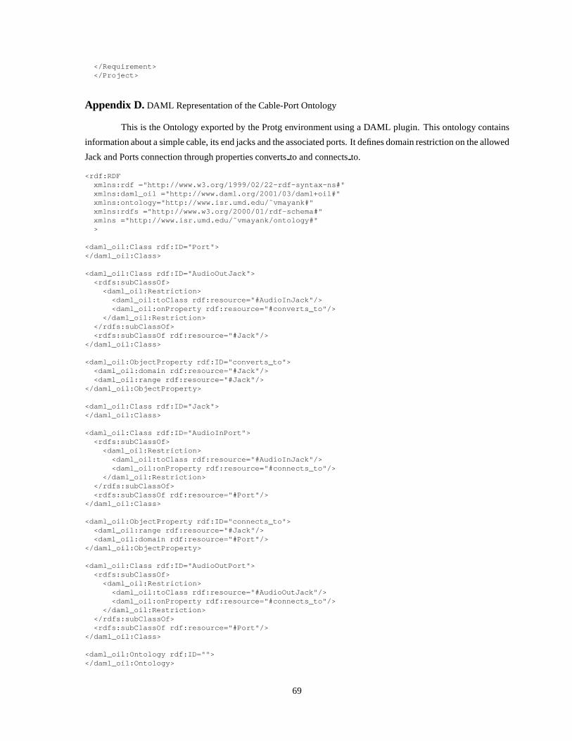
</Requirement></Project>
Appendix D. DAML Representation of the Cable-Port Ontology
This is the Ontology exported by the Protg environment usinga DAML plugin. This ontology contains
information about a simple cable, its end jacks and the associated ports. It defines domain restriction on the allowed
Jack and Ports connection through properties convertsto and connectsto.
<rdf:RDFxmlns:rdf ="http://www.w3.org/1999/02/22-rdf-syntax- ns#"xmlns:daml_oil ="http://www.daml.org/2001/03/daml+oi l#"xmlns:ontology="http://www.isr.umd.edu/˜vmayank#"xmlns:rdfs ="http://www.w3.org/2000/01/rdf-schema#"xmlns ="http://www.isr.umd.edu/˜vmayank/ontology#">
<daml_oil:Class rdf:ID="Port"></daml_oil:Class>
<daml_oil:Class rdf:ID="AudioOutJack"><rdfs:subClassOf>
<daml_oil:Restriction><daml_oil:toClass rdf:resource="#AudioInJack"/><daml_oil:onProperty rdf:resource="#converts_to"/>
</daml_oil:Restriction></rdfs:subClassOf><rdfs:subClassOf rdf:resource="#Jack"/>
</daml_oil:Class>
<daml_oil:ObjectProperty rdf:ID="converts_to"><daml_oil:domain rdf:resource="#Jack"/><daml_oil:range rdf:resource="#Jack"/>
</daml_oil:ObjectProperty>
<daml_oil:Class rdf:ID="Jack"></daml_oil:Class>
<daml_oil:Class rdf:ID="AudioInPort"><rdfs:subClassOf>
<daml_oil:Restriction><daml_oil:toClass rdf:resource="#AudioInJack"/><daml_oil:onProperty rdf:resource="#connects_to"/>
</daml_oil:Restriction></rdfs:subClassOf><rdfs:subClassOf rdf:resource="#Port"/>
</daml_oil:Class>
<daml_oil:ObjectProperty rdf:ID="connects_to"><daml_oil:range rdf:resource="#Jack"/><daml_oil:domain rdf:resource="#Port"/>
</daml_oil:ObjectProperty>
<daml_oil:Class rdf:ID="AudioOutPort"><rdfs:subClassOf>
<daml_oil:Restriction><daml_oil:toClass rdf:resource="#AudioOutJack"/><daml_oil:onProperty rdf:resource="#connects_to"/>
</daml_oil:Restriction></rdfs:subClassOf><rdfs:subClassOf rdf:resource="#Port"/>
</daml_oil:Class>
<daml_oil:Ontology rdf:ID=""></daml_oil:Ontology>
69

<daml_oil:Class rdf:ID="AudioInJack"><rdfs:subClassOf>
<daml_oil:Restriction><daml_oil:toClass rdf:resource="#AudioOutJack"/><daml_oil:onProperty rdf:resource="#converts_to"/>
</daml_oil:Restriction></rdfs:subClassOf><rdfs:subClassOf rdf:resource="#Jack"/>
</daml_oil:Class>
</rdf:RDF>
Appendix E. Jess Assertions and the Rules for the Cable-Port Ontology
Here is the complete Jess input file, which has been generatedthrough the use of the DAMLJessKB
plugin to covert the Ontology into a set of facts (collectionof RDF triplets prefixed by the PropertyValue key), and
a set of rules, generated from the instances created in the GUI.
When Rete algorithm is run on the provided set of facts, it checks the cable configuration and comes out
with an assertion whether the cable jacks and associated ports are consistent as per the ontology definitions or not,
and produces an output informing the results.
;; ================================================= ===;; ************** Define Initial Facts ****************;; ================================================= ===
(deffacts iniial-condition-from-ontology
(PropertyValue http://www.w3.org/1999/02/22-rdf-synt ax-ns#typehttp://www.isr.umd.edu/˜vmayank/SimpleOntology.daml #Porthttp://www.daml.org/2001/03/daml+oil#Class)
(PropertyValue http://www.w3.org/1999/02/22-rdf-synt ax-ns#typehttp://www.isr.umd.edu/˜vmayank/SimpleOntology.daml #AudioOutJackhttp://www.daml.org/2001/03/daml+oil#Class)
(PropertyValue http://www.w3.org/1999/02/22-rdf-synt ax-ns#typehttp://www.isr.umd.edu/˜vmayank/SimpleOntology.daml #anon2http://www.daml.org/2001/03/daml+oil#Restriction)
(PropertyValue http://www.daml.org/2001/03/daml+oil# toClasshttp://www.isr.umd.edu/˜vmayank/SimpleOntology.daml #anon2http://www.isr.umd.edu/˜vmayank/SimpleOntology.daml #AudioInJack)
(PropertyValue http://www.daml.org/2001/03/daml+oil# onPropertyhttp://www.isr.umd.edu/˜vmayank/SimpleOntology.daml #anon2http://www.isr.umd.edu/˜vmayank/SimpleOntology.daml #converts_to)
(PropertyValuehttp://www.w3.org/2000/01/rdf-schema#subClassOfhttp://www.isr.umd.edu/˜vmayank/SimpleOntology.daml #AudioOutJackhttp://www.isr.umd.edu/˜vmayank/SimpleOntology.daml #anon2)
(PropertyValuehttp://www.w3.org/2000/01/rdf-schema#subClassOfhttp://www.isr.umd.edu/˜vmayank/SimpleOntology.daml #AudioOutJackhttp://www.isr.umd.edu/˜vmayank/SimpleOntology.daml #Jack)
(PropertyValuehttp://www.w3.org/1999/02/22-rdf-syntax-ns#typehttp://www.isr.umd.edu/˜vmayank/SimpleOntology.daml #converts_tohttp://www.daml.org/2001/03/daml+oil#ObjectProperty )
70

(PropertyValue http://www.daml.org/2001/03/daml+oil# domainhttp://www.isr.umd.edu/˜vmayank/SimpleOntology.daml #converts_tohttp://www.isr.umd.edu/˜vmayank/SimpleOntology.daml #Jack)
(PropertyValue http://www.daml.org/2001/03/daml+oil# rangehttp://www.isr.umd.edu/˜vmayank/SimpleOntology.daml #converts_tohttp://www.isr.umd.edu/˜vmayank/SimpleOntology.daml #Jack)
(PropertyValuehttp://www.w3.org/1999/02/22-rdf-syntax-ns#typehttp://www.isr.umd.edu/˜vmayank/SimpleOntology.daml #Jackhttp://www.daml.org/2001/03/daml+oil#Class)
(PropertyValuehttp://www.w3.org/1999/02/22-rdf-syntax-ns#typehttp://www.isr.umd.edu/˜vmayank/SimpleOntology.daml #AudioInPorthttp://www.daml.org/2001/03/daml+oil#Class)
(PropertyValuehttp://www.w3.org/1999/02/22-rdf-syntax-ns#typehttp://www.isr.umd.edu/˜vmayank/SimpleOntology.daml #anon11http://www.daml.org/2001/03/daml+oil#Restriction)
(PropertyValue http://www.daml.org/2001/03/daml+oil# toClasshttp://www.isr.umd.edu/˜vmayank/SimpleOntology.daml #anon11http://www.isr.umd.edu/˜vmayank/SimpleOntology.daml #AudioInJack)
(PropertyValue http://www.daml.org/2001/03/daml+oil# onPropertyhttp://www.isr.umd.edu/˜vmayank/SimpleOntology.daml #anon11http://www.isr.umd.edu/˜vmayank/SimpleOntology.daml #connects_to)
(PropertyValuehttp://www.w3.org/2000/01/rdf-schema#subClassOfhttp://www.isr.umd.edu/˜vmayank/SimpleOntology.daml #AudioInPorthttp://www.isr.umd.edu/˜vmayank/SimpleOntology.daml #anon11)
(PropertyValuehttp://www.w3.org/2000/01/rdf-schema#subClassOfhttp://www.isr.umd.edu/˜vmayank/SimpleOntology.daml #AudioInPorthttp://www.isr.umd.edu/˜vmayank/SimpleOntology.daml #Port)
(PropertyValuehttp://www.w3.org/1999/02/22-rdf-syntax-ns#typehttp://www.isr.umd.edu/˜vmayank/SimpleOntology.daml #connects_tohttp://www.daml.org/2001/03/daml+oil#ObjectProperty )
(PropertyValue http://www.daml.org/2001/03/daml+oil# rangehttp://www.isr.umd.edu/˜vmayank/SimpleOntology.daml #connects_tohttp://www.isr.umd.edu/˜vmayank/SimpleOntology.daml #Jack)
(PropertyValue http://www.daml.org/2001/03/daml+oil# domainhttp://www.isr.umd.edu/˜vmayank/SimpleOntology.daml #connects_tohttp://www.isr.umd.edu/˜vmayank/SimpleOntology.daml #Port)
(PropertyValuehttp://www.w3.org/1999/02/22-rdf-syntax-ns#typehttp://www.isr.umd.edu/˜vmayank/SimpleOntology.daml #AudioOutPorthttp://www.daml.org/2001/03/daml+oil#Class)
(PropertyValuehttp://www.w3.org/1999/02/22-rdf-syntax-ns#typehttp://www.isr.umd.edu/˜vmayank/SimpleOntology.daml #anon19http://www.daml.org/2001/03/daml+oil#Restriction)
(PropertyValue http://www.daml.org/2001/03/daml+oil# toClasshttp://www.isr.umd.edu/˜vmayank/SimpleOntology.daml #anon19http://www.isr.umd.edu/˜vmayank/SimpleOntology.daml #AudioOutJack)
71

(PropertyValue http://www.daml.org/2001/03/daml+oil# onPropertyhttp://www.isr.umd.edu/˜vmayank/SimpleOntology.daml #anon19http://www.isr.umd.edu/˜vmayank/SimpleOntology.daml #connects_to)
(PropertyValuehttp://www.w3.org/2000/01/rdf-schema#subClassOfhttp://www.isr.umd.edu/˜vmayank/SimpleOntology.daml #AudioOutPorthttp://www.isr.umd.edu/˜vmayank/SimpleOntology.daml #anon19)
(PropertyValuehttp://www.w3.org/2000/01/rdf-schema#subClassOfhttp://www.isr.umd.edu/˜vmayank/SimpleOntology.daml #AudioOutPorthttp://www.isr.umd.edu/˜vmayank/SimpleOntology.daml #Port)
(PropertyValuehttp://www.w3.org/1999/02/22-rdf-syntax-ns#typehttp://www.isr.umd.edu/˜vmayank/SimpleOntology.daml #AudioInJackhttp://www.daml.org/2001/03/daml+oil#Class)
(PropertyValuehttp://www.w3.org/1999/02/22-rdf-syntax-ns#typehttp://www.isr.umd.edu/˜vmayank/SimpleOntology.daml #anon24http://www.daml.org/2001/03/daml+oil#Restriction)
(PropertyValue http://www.daml.org/2001/03/daml+oil# toClasshttp://www.isr.umd.edu/˜vmayank/SimpleOntology.daml #anon24http://www.isr.umd.edu/˜vmayank/SimpleOntology.daml #AudioOutJack)
(PropertyValue http://www.daml.org/2001/03/daml+oil# onPropertyhttp://www.isr.umd.edu/˜vmayank/SimpleOntology.daml #anon24http://www.isr.umd.edu/˜vmayank/SimpleOntology.daml #converts\_to)
(PropertyValuehttp://www.w3.org/2000/01/rdf-schema#subClassOfhttp://www.isr.umd.edu/˜vmayank/SimpleOntology.daml #AudioInJackhttp://www.isr.umd.edu/˜vmayank/SimpleOntology.daml #anon24)
(PropertyValuehttp://www.w3.org/2000/01/rdf-schema#subClassOfhttp://www.isr.umd.edu/˜vmayank/SimpleOntology.daml #AudioInJackhttp://www.isr.umd.edu/˜vmayank/SimpleOntology.daml #Jack)
(PropertyValuehttp://www.w3.org/1999/02/22-rdf-syntax-ns#typehttp://www.isr.umd.edu/˜vmayank/SimpleOntology.damlhttp://www.daml.org/2001/03/daml+oil#Ontology))
;; ================================================= ===;; ************* Reset the known facts ****************;; ================================================= ===(reset)
;; ================================================= ===;; Rule 1: This rule if fired accounts for the fact;; that the cable has correct jacks at its two ends and;; produces such an output;; ================================================= ===(defrule allowed-jack-config(PropertyValuehttp://www.daml.org/2001/03/daml+oil#toClass?anon;; ================================================= ===;; This Jack A instance is generated programmatically;; using the Java API;; =========+======================================= ===http://www.isr.umd.edu/˜vmayank/SimpleOntology.daml #AudioOutJack)
72
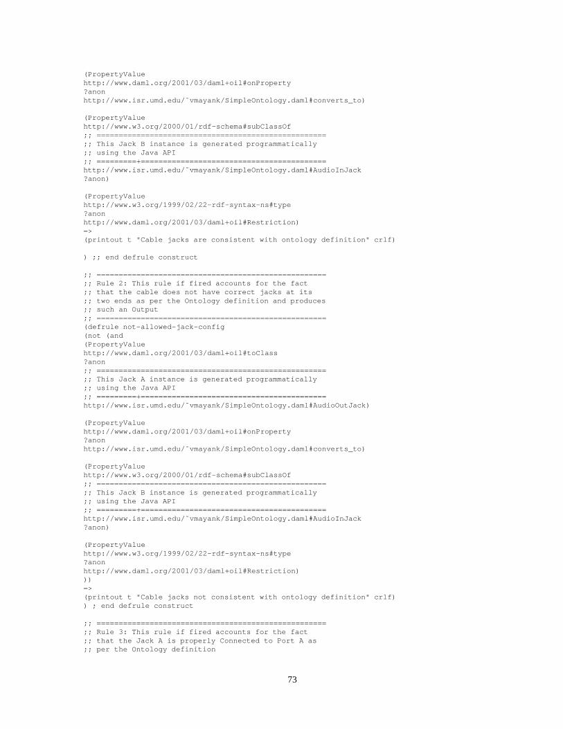
(PropertyValuehttp://www.daml.org/2001/03/daml+oil#onProperty?anonhttp://www.isr.umd.edu/˜vmayank/SimpleOntology.daml #converts_to)
(PropertyValuehttp://www.w3.org/2000/01/rdf-schema#subClassOf;; ================================================= ===;; This Jack B instance is generated programmatically;; using the Java API;; =========+======================================= ===http://www.isr.umd.edu/˜vmayank/SimpleOntology.daml #AudioInJack?anon)
(PropertyValuehttp://www.w3.org/1999/02/22-rdf-syntax-ns#type?anonhttp://www.daml.org/2001/03/daml+oil#Restriction)=>(printout t "Cable jacks are consistent with ontology defin ition" crlf)
) ;; end defrule construct
;; ================================================= ===;; Rule 2: This rule if fired accounts for the fact;; that the cable does not have correct jacks at its;; two ends as per the Ontology definition and produces;; such an Output;; ================================================= ===(defrule not-allowed-jack-config(not (and(PropertyValuehttp://www.daml.org/2001/03/daml+oil#toClass?anon;; ================================================= ===;; This Jack A instance is generated programmatically;; using the Java API;; =========+======================================= ===http://www.isr.umd.edu/˜vmayank/SimpleOntology.daml #AudioOutJack)
(PropertyValuehttp://www.daml.org/2001/03/daml+oil#onProperty?anonhttp://www.isr.umd.edu/˜vmayank/SimpleOntology.daml #converts_to)
(PropertyValuehttp://www.w3.org/2000/01/rdf-schema#subClassOf;; ================================================= ===;; This Jack B instance is generated programmatically;; using the Java API;; =========+======================================= ===http://www.isr.umd.edu/˜vmayank/SimpleOntology.daml #AudioInJack?anon)
(PropertyValuehttp://www.w3.org/1999/02/22-rdf-syntax-ns#type?anonhttp://www.daml.org/2001/03/daml+oil#Restriction)))=>(printout t "Cable jacks not consistent with ontology defin ition" crlf)) ; end defrule construct
;; ================================================= ===;; Rule 3: This rule if fired accounts for the fact;; that the Jack A is properly Connected to Port A as;; per the Ontology definition
73

;; ================================================= ===(defrule allowed-jacka-porta-config(PropertyValuehttp://www.w3.org/1999/02/22-rdf-syntax-ns#type?anonhttp://www.daml.org/2001/03/daml+oil#Restriction)
(PropertyValuehttp://www.daml.org/2001/03/daml+oil#toClass?anon;; ================================================= ===;; This Jack A instance is generated programmatically;; using the Java API;; =========+======================================= ===http://www.isr.umd.edu/˜vmayank/SimpleOntology.daml #AudioOutJack)
(PropertyValuehttp://www.daml.org/2001/03/daml+oil#onProperty?anonhttp://www.isr.umd.edu/˜vmayank/SimpleOntology.daml #connects_to)
(PropertyValuehttp://www.w3.org/2000/01/rdf-schema#subClassOf;; ================================================= ===;; This Port A instance is generated programmatically;; using the Java API;; =========+======================================= ===http://www.isr.umd.edu/˜vmayank/SimpleOntology.daml #AudioOutPort?anon)=>(printout t "Jack A consistent with Port A as per ontology def inition" crlf)) ;; end defrule construct
;; ================================================= ===;; Rule 4: This rule if fired accounts for the fact;; that the Jack A is not properly Connected to Port A;; as per the Ontology definition and produces the;; error message;; ================================================= ===(defrule not-allowed-jacka-porta-config(not (and(PropertyValuehttp://www.w3.org/1999/02/22-rdf-syntax-ns#type?anonhttp://www.daml.org/2001/03/daml+oil#Restriction)
(PropertyValuehttp://www.daml.org/2001/03/daml+oil#toClass?anon;; ================================================= ===;; This Jack A instance is generated programmatically;; using the Java API;; =========+======================================= ===http://www.isr.umd.edu/˜vmayank/SimpleOntology.daml #AudioOutJack)
(PropertyValuehttp://www.daml.org/2001/03/daml+oil#onProperty?anonhttp://www.isr.umd.edu/˜vmayank/SimpleOntology.daml #connects_to)
(PropertyValuehttp://www.w3.org/2000/01/rdf-schema#subClassOf;; ================================================= ===;; This Port A instance is generated programmatically;; using the Java API;; =========+======================================= ===http://www.isr.umd.edu/˜vmayank/SimpleOntology.daml #AudioOutPort?anon)
74

))=>(printout t crlf "Jack A not consistent with Port A as per onto logy definition" crlf)(printout t "If you are sure that cable is compatible with the port try reversing the cable" crlf)) ;; end defrule construct
;; ================================================= ===;; Rule 5: This rule if fired accounts for the fact;; that the Jack B is properly Connected to Port B as;; per the Ontology definition and produces a message;; ================================================= ===(defrule allowed-jackb-portb-config(PropertyValuehttp://www.w3.org/1999/02/22-rdf-syntax-ns#type?anonhttp://www.daml.org/2001/03/daml+oil#Restriction)
(PropertyValuehttp://www.daml.org/2001/03/daml+oil#toClass?anon;; ================================================= ===;; This Jack B instance is generated programmatically;; using the Java API;; =========+======================================= ===http://www.isr.umd.edu/˜vmayank/SimpleOntology.daml #AudioInJack)
(PropertyValuehttp://www.daml.org/2001/03/daml+oil#onProperty?anonhttp://www.isr.umd.edu/˜vmayank/SimpleOntology.daml #connects_to)
(PropertyValuehttp://www.w3.org/2000/01/rdf-schema#subClassOf;; ================================================= ===;; This Port B instance is generated programmatically;; using the Java API;; =========+======================================= ===http://www.isr.umd.edu/˜vmayank/SimpleOntology.daml #AudioInPort?anon)=>(printout t "Jack B consistent with Port B as per ontology def inition" crlf)) ;; end defrule construct
;; ================================================= ===;; Rule 6: This rule if fired accounts for the fact;; that the Jack B is not properly Connected to Port B;; as per the Ontology definition and produces an error;; message;; ================================================= ===(defrule not-allowed-jackb-portb-config(not (and(PropertyValuehttp://www.w3.org/1999/02/22-rdf-syntax-ns#type?anonhttp://www.daml.org/2001/03/daml+oil#Restriction)
(PropertyValuehttp://www.daml.org/2001/03/daml+oil#toClass?anon;; ================================================= ===;; This Jack B instance is generated programmatically;; using the Java API;; =========+======================================= ===http://www.isr.umd.edu/˜vmayank/SimpleOntology.daml #AudioInJack)
(PropertyValuehttp://www.daml.org/2001/03/daml+oil#onProperty?anon
75

http://www.isr.umd.edu/˜vmayank/SimpleOntology.daml #connects_to)
(PropertyValuehttp://www.w3.org/2000/01/rdf-schema#subClassOf;; ================================================= ===;; This Port B instance is generated programmatically;; using the Java API;; =========+======================================= ===http://www.isr.umd.edu/˜vmayank/SimpleOntology.daml #AudioInPort?anon)))=>(printout t crlf "Jack B not consistent with Port B as per onto logy definition" crlf)(printout t "If you are sure that cable is compatible with the port try reversing the cable" crlf)) ;; end defrule construct
;; run the Rete on the above facts and rules
(run)
76