Requirements analysis of technology enablers for the flexi ... · PDF fileRequirements...
43
STRAUSS Scalable and efficient orchestration of Ethernet services using software-defined and flexible optical networks Deliverable D2.1 Requirements analysis of technology enablers for the flexi- grid optical path-packet infrastructure for Ethernet transport Page 1 of 43 Deliverable D2.1 Requirements analysis of technology enablers for the flexi-grid optical path-packet infrastructure for Ethernet transport Status and Version: Version 3.0, Final Date of issue: 31.05.2014 Distribution: Public Author(s): Name Partner Michael Schlosser Fraunhofer HHI Luz Fernandez del Rosal Fraunhofer HHI Kai Habel Fraunhofer HHI Michela Svaluto Moreolo CTTC Josep M. Fàbrega CTTC Victor Lopez TID Felipe Jimenez Arribas Luis Miguel Contreras Shuangyi Yan TID TID UNIVBRIS Bijan R.Rofoee UNIVBRIS George Zervas UNIVBRIS Dimitra Simeonidou UNIVBRIS Ken-ichi Kitayama OSAKAU Yuki Yoshida OSAKAU Masato Nishihara FUJITSU Tomoo Takahara FUJITSU Toshiki Tanaka FUJITSU
Transcript of Requirements analysis of technology enablers for the flexi ... · PDF fileRequirements...

STRAUSS Scalable and efficient orchestration of Ethernet services
using software-defined and flexible optical networks
Deliverable D2.1 Requirements analysis of
technology enablers for the flexi-grid optical path-packet
infrastructure for Ethernet transport
Page 1 of 43
Deliverable D2.1
Requirements analysis of technology enablers for the flexi-grid optical path-packet infrastructure for Ethernet transport
Status and Version: Version 3.0, Final
Date of issue: 31.05.2014
Distribution: Public
Author(s): Name Partner
Michael Schlosser Fraunhofer HHI
Luz Fernandez del Rosal Fraunhofer HHI
Kai Habel Fraunhofer HHI
Michela Svaluto Moreolo CTTC
Josep M. Fàbrega CTTC
Victor Lopez TID
Felipe Jimenez Arribas
Luis Miguel Contreras
Shuangyi Yan
TID
TID
UNIVBRIS
Bijan R.Rofoee UNIVBRIS
George Zervas UNIVBRIS
Dimitra Simeonidou UNIVBRIS
Ken-ichi Kitayama OSAKAU
Yuki Yoshida OSAKAU
Masato Nishihara FUJITSU
Tomoo Takahara FUJITSU
Toshiki Tanaka FUJITSU

STRAUSS Scalable and efficient orchestration of Ethernet services
using software-defined and flexible optical networks
Deliverable D2.1 Requirements analysis of
technology enablers for the flexi-grid optical path-packet
infrastructure for Ethernet transport
Page 2 of 43
Jens C. Rasmussen FUJITSU
Checked by:
Michela Svaluto Moreolo CTTC
Yuki Yoshida OSAKAU

STRAUSS Scalable and efficient orchestration of Ethernet services
using software-defined and flexible optical networks
Deliverable D2.1 Requirements analysis of
technology enablers for the flexi-grid optical path-packet
infrastructure for Ethernet transport
Page 3 of 43
Executive summary
This document contains the work of WP2 of the STRAUSS project regarding the requirement analysis of technology enablers for the flexi-grid optical path-packet infrastructure for Ethernet transport.
The STRAUSS architecture considers two different switching technologies. These technologies are flexi-grid optical circuit switching (OCS) and optical packet switching (OPS). For both technologies the main technological as well as the operator requirements are described.
For the flexi-grid OCS one key component is the software-defined and bandwidth-variable transceiver. Different transceiver designs based on single-carrier technologies and multicarrier technologies, such as the orthogonal frequency division multiplexing (OFDM) and discrete multi-tone (DMT), are considered here. Another key component is the node for the flexi-grid OCS, which is also depicted.
For the OPS the general approach with a new photonic layer is specified. The key concept of this photonic layer is to simplify the Ethernet bridging or switching functions as much as possible, by exploiting the inherent nature of photonics and optics such as its high speed, abundant bandwidth, and all-optical processing capability. The intention is to create a new photonic-native data transport protocol, not necessarily emulating the conventional Ethernet protocol, while retaining the interface with the existing protocols at the edges. It is based on fixed length packets with a variable payload.
Finally a possible solution for the interface between the OPS and OCS network is shown. The OPS/OCS interface is based on a ultra-high performance optoelectronics platform of field programmable gate arrays (FPGAs). It will encapsulate the Ethernet packets to the OCS network with grooming and aggregation functions.
Beside the requirements some experimental results for specific transceiver solutions are reported.

STRAUSS Scalable and efficient orchestration of Ethernet services
using software-defined and flexible optical networks
Deliverable D2.1 Requirements analysis of
technology enablers for the flexi-grid optical path-packet
infrastructure for Ethernet transport
Page 4 of 43
Table of Contents
Executive summary 3
Table of Contents 4
1 Introduction 5
2 Overview 7
2.1 Flexi-grid OCS 7
2.2 OPS approach 8
2.3 Integrated OPS/OCS interface 9
3 General Operator Requirements 10
4 Requirements for transceivers, optical nodes and interfaces 11
4.1 Software-defined programmable and variable-bandwidth transceivers 11 4.1.1 OFDM Transceiver 12 4.1.2 Real-time OFDM Transmitter 17 4.1.3 DMT Transceiver 22 4.1.4 Superchannel signal generator with single carrier modulation 25
4.2 Flexi-grid OCS & OPS nodes and interface 28 4.2.1 Flexible/adaptable optical nodes for flexi-grid DWDM networks 28 4.2.2 OPS node and OPS network 33 4.2.3 Interface between OPS and OCS network 34
5 Conclusions 37
6 References 38
7 List of acronyms 40
8 Acknowledgements 42
Document History 43

STRAUSS Scalable and efficient orchestration of Ethernet services
using software-defined and flexible optical networks
Deliverable D2.1 Requirements analysis of
technology enablers for the flexi-grid optical path-packet
infrastructure for Ethernet transport
Page 5 of 43
1 Introduction
Increasing traffic demands e.g. from datacenters (DC) and new flexible services like bandwidth on demand are huge challenges for operators with respect to limit their CAPEX and OPEX. Starting from the Local Area Networks (LAN) in the recent years Ethernet based technologies became a cost efficient solution also for Metro Area Networks (MAN) and this development goes further on to the transport network segment. The STRAUSS project focuses on a future software defined optical Ethernet transport network architecture. It is shown in Figure 1 and composed of four layers: The transport network infrastructure layer, the transport network virtualization layer, the virtual infrastructure control and management, and an end-to-end service & network orchestration layer.
Figure 1: STRAUSS architecture

STRAUSS Scalable and efficient orchestration of Ethernet services
using software-defined and flexible optical networks
Deliverable D2.1 Requirements analysis of
technology enablers for the flexi-grid optical path-packet
infrastructure for Ethernet transport
Page 6 of 43
The four layers can be described as follows:
• Transport network infrastructure layer. Two technologies are used in the data plane: (1) optical packet switching and (2) elastic optical technology. Data plane technologies are studied in this WP and described further.
• Transport network virtualization layer. This layer enables the partitioning of physical infrastructure into virtual resources. The characteristics of the optical data plane are taken into account in this layer to compose the virtual infrastructures over multiple technology domains, which is part of WP3.
• Virtual infrastructure control and management. Thanks to the utilization of GMPLS and OpenFlow it is possible to control the virtual layer or even the physical infrastructure, which is addressed in WP3.
• End-to-end service & network orchestration layer. To do the orchestration between the domains and technology a SDN layer is added to enable the interworking of different control plane paradigms and, consequently, the end-to-end Ethernet services, which is also part of WP3.
The physical infrastructure covers heterogeneous technologies based on:
• Optical packet switching (OPS) technology to provide scalable and cost/energy-efficient traffic grooming at sub-wavelength granularity
• Flexi-grid optical circuit switching (OCS) to provide flexible spectrum management capabilities
• Software-defined and sliceable (multi-flow) bandwidth-variable transponders (BVT) supporting multiple data flows with different modulation formats and bit rates.
The design and development of a scalable, reliable, virtualizable, and cost/energy-efficient optical Ethernet transport infrastructure is aimed for data rates beyond 100 Gb/s. It combines the flexible bandwidth capacity provided by sliceable all-optical networks and the benefits of optical packet switching such as statistical multiplexing.

STRAUSS Scalable and efficient orchestration of Ethernet services
using software-defined and flexible optical networks
Deliverable D2.1 Requirements analysis of
technology enablers for the flexi-grid optical path-packet
infrastructure for Ethernet transport
Page 7 of 43
2 Overview
2.1 Flexi-grid OCS
Deployment of high-speed over 100G coherent optical networks is currently underway, to address the ever increasing of the volume of traffic in core networks in recent decades. In future, high-order modulation formats will be adopted to further enhance the total capacity, but with a trade-off between capacity and distance. In addition to the traffic volume, the traffic patterns also become highly variable and complex. The varied requirements of different applications, changes in customer behaviour, uneven traffic growth, or network failures will lead to the uncertainty in traffic demands, granularity, and geographic and temporal distributions. To handle the uncertainty nature of Ethernet traffic, optical circuit switching network should be evolved to provide more flexibility and more functions.
The flexi-grid optical circuit switching (OCS) networks or the ‘Elastic’ optical networks are the potential solution to bring more flexibility and efficiency to optical networks by introducing adaptive optical spectrum allocation. Compared with the fixed grid networks, each channel will occupy even multiples of 6.25 GHz spectral slots in flexi-grid OCS networks. The adaptive spectrum allocation incorporated with coherent transport technologies will introduce several flexibility strategies to the OCS networks. Firstly, signals can adopt different baud rate with variable occupied bandwidth. The mixed line rate (MLR) networks are compatible with early deployed optical transmitter with 10G or 40G line rate, to fully use the available network resource. However, baud rate adaptation provides little margin adaption [Aug13], and the MLR signals can lead to fragmentation of the optical spectrum. The second flexible feature of flexi-grid OCS networks come from modulation format adaption. The required OSNRs is largely dependent on modulation format, thus signals with variable modulation format will have different range coverage. The flexibility provides differentiated services related to the transmission distance. Transmitters supporting multi-formats provide a method for spectrum defragmentation [Cho13]. Usually, the flexi-grid OCS system will adopt both flexibility strategies to use the optical bandwidth more efficiently. Another flexible feature is the channel spacing adjustment. The steepness of occupied optical bandwidth for Nyquist WDM signals are strongly related to the pulse shaping functions. Channel spacing closer to the symbol rate will require more advanced or power-consumed transmitter side digital signal processing. With a looser spacing, we can trade spectral efficiency with transponder cost.
To realize the aforementioned flexibility, the OCS network requires the evolution of several data plane technologies. The key enabling technologies include software-defined sliceable BVT technology, and flexible/adaptable optical nodes for flexi-grid DWDM networks.
Software-defined sliceable bandwidth variable transponder technology
Software-defined BVT adopts multiple modulation formats or variable bandwidth occupancy, according to the requirements and usage scenarios, in order to maximize the flexibility and scalability of the network and to minimize its cost and energy consumption. Numerous BVT designs have been proposed based on single-carrier technologies [Zhu13], or multicarrier technologies, such as the orthogonal frequency division multiplexing (OFDM) [Sva13] and discrete multi-tone (DMT) [ieee802-6]. By introducing the superchannel concept, the transmitter can provide much higher capacity link for future Terabit Ethernet transmission [Liu2014].

STRAUSS Scalable and efficient orchestration of Ethernet services
using software-defined and flexible optical networks
Deliverable D2.1 Requirements analysis of
technology enablers for the flexi-grid optical path-packet
infrastructure for Ethernet transport
Page 8 of 43
Flexible/adaptable optical nodes for flexi-grid DWDM networks
In flexi-grid OCS networks, the optical signal in each channel will adopt different baudrate, different modulation format, and thus a different occupied bandwidth. The common fixed-grid arrayed waveguide grating (AWG) can’t handle the add/drop function in the reconfigurable optical add drop multiplexer (ROADM). A reconfigurable wavelength selective switch (WSS) will replace AWGs to provide add/drop operation with arbitrary optical bandwidth, to support the more complex and mixed optical flows. In addition, the optical node should also evolve to handle flexi-grid optical signals and provide a more flexible and efficient inter-connections, which will allow arbitrary spectrum switching, sub-wavelength switching and wide-spectrum conversion. Colorless directionless contentionless (CD/C) ROADM architectures should be included in the optical nodes to provide bandwidth pre-positioning, bandwidth on demand and optical layer re-optimization/restoration. The optical node also needs to support virtualization to create different virtual topologies that provide distinct functionalities, e.g. migration from fixed-grid to flexi-grid, or in a shared infrastructure scenario on-demand provisioning of network infrastructure services. The optical node with static structure faces great challenges to realize the aforementioned functions. Thus the structure of the optical node should be also reconfigurable to provide further flexibility.
2.2 OPS approach
The analysis of Big Data, e.g. based upon real-time complex event processing (CEP), will be performed by exchanging huge quantities of data on inter-DC and intra-DC networks. The size of data sets that are feasible to be processed in a reasonable amount of time is often limited by not only the processing capability but also the bandwidth and the latency of data transfer over the networks. Therefore, a huge bandwidth as well as low latency will be required for the network.
As the total fibre transmission capacity increases, the technologies for dividing the capacity into many flexible paths are also evolving. One such technology is packet optical transport system, where electric packet switches are integrated with WDM optical cross-connects to create flexible sub-wavelength paths with arbitrary bandwidths. Packets provide sub-wavelength “logical” paths, while a wavelength serves as a physical path.
In order to save energy, CAPEX and OPEX, a novel network architecture is needed to overcome the limitations of the current router-based networks. There has been a transition or departure from legacy IP over DWDM to simplified layer-2 switching. Layer-2 switches such as Ethernet switches are in widespread use in metro-access networks. Beyond 100 Gb/s, however, the electrical switch cannot be as efficient as the optical counterpart due to large forwarding delay and poor power efficiency. An innovative approach to layer-2 will be needed to improve the power consumption and packet forwarding delay of electrical switches.
The enabler will be photonic layer-2 (P-L2) networking. The key concept of the P-L2 is to simplify the Ethernet bridging or switching functions as much as possible, by exploiting the inherent nature of photonics and optics such as its high speed, abundant bandwidth, and all-optical processing capability. The intention is to create a new photonic-native data transport protocol, not necessarily emulating the conventional Ethernet protocol, while retaining the interface with the existing protocols at the edges.
In Figure 2 the architecture of P-L2 network is compared with that of an Ethernet. A typical Ethernet is a multi-hop network of Ethernet bridges or switches, in which all data packets are processed by electrical circuits for the physical (PHY) and media access control (Eth-MAC) layers (Figure 2(a)).

STRAUSS Scalable and efficient orchestration of Ethernet services
using software-defined and flexible optical networks
Deliverable D2.1 Requirements analysis of
technology enablers for the flexi-grid optical path-packet
infrastructure for Ethernet transport
Page 9 of 43
In the P-L2 architecture, all-optical signal processing is adopted and combined with the digital electronics in such a way that the best of both can be fully exploited (Figure 2(b)). The PHY layer at the P-L2 edge converts the data signals from the PL2-MAC layer into optical signals and transmits them to a P-L2 bridge over transparent optical channels with a flexible bandwidth of up to one Tb/s. P-L2 bridges transfer the optical data signals from P-L2 edges to their destinations through optical switches without O-E-O. At the P-L2 edge, the PL2-MAC layer converts the data packets of the existing protocols such as Ethernet into data signals for P-L2. By employing the SDN technology, address resolutions are managed from the outside. For the P-L2 bridge, optical packet switching using high-speed space switches or high-speed tunable lasers will be used to fully utilize the optical transmission capability and to realize data aggregation or distribution in the optical domain.
P-L2 can divide the bandwidth of each wavelength into many logical paths with narrower bandwidths without using external electrical packet switches. P-L2 enables network virtualization which differs from the legacy virtualization, outnumbering slices from 1 Gb/s to 100 Gb/s.
Figure 2: (a) Legacy multi-hop Ethernet switch network, and (b) Photonic layer-2 network
2.3 Integrated OPS/OCS interface
The two optical switching techniques, OPS and OCS, will be used to provide network virtualization with a flexible bandwidth resource. OPS will be preferably used for transporting bursty data, while, OCS will primarily be used for streaming data. To take full advantage of both OPS and OCS networks, OPS/OCS-integrated interface will be required to interconnect the two technological domains of OPS and OCS. The OPS/OCS interface will enable on-demand provisioning of sliceable bandwidth via either OPS or OCS, to provide network virtualization with flexible bandwidth.

STRAUSS Scalable and efficient orchestration of Ethernet services
using software-defined and flexible optical networks
Deliverable D2.1 Requirements analysis of
technology enablers for the flexi-grid optical path-packet
infrastructure for Ethernet transport
Page 10 of 43
3 General Operator Requirements
The goal of this section is to define the general requirements in an operator’s network of future optical infrastructures for optical transport beyond 100 Gb/s, by combining OPS and flexi-grid OCS technologies.
The optical transmission technologies are evolving to enable more network efficiency, flexibility and scalability to cope with the needs of the future Internet. OPS and flexible OCS technologies have been analysed for years, because they fulfil the requirements for this evolution. However, they cannot be pondered as a near-term solution because they are still immature. The utilization of flexi-grid node architectures allows an improvement in the bandwidth utilization of the resources, because they can dynamically configure the data-rate by software on demand. OPS and flexible OCS solution will enable the high-capacity optical communication systems that will require future networks.
Papers on OPS often include introductory comments about the advantages afforded by OPS and claims that OPS will be needed in the future telecommunications network. In particular, many researchers have argued that limitations of today’s electronic packet switching technologies will constrain the ability of the network to meet the rising demand for more data. These limitations are commonly identified in terms of 1) energy consumption, (e.g., electronic packet switches are power hungry), and 2) capacity (e.g., electronic packet switches are limited in capacity by slow and inefficient optical-to-electronic and electronic- to-optical converters, electronics is slow compared to optics, and so on). It is commonly argued that OPS will overcome these speed and/or energy consumption problems. The main targets is the design of these networks assuring scalability, flexibility, end-to-end performance and last, but not the least low cost and limited energy consumption.
Flexi-grid OCS networks enable the efficient utilization of the optical spectrum. For this reason, STRAUSS project extensively investigates set of transmission and modulation format techniques for different transponder architecture. The BVT are key elements in the data plane STRAUSS solutions. There is not a clear architecture for the BVT. This is the reason why the project will consider evaluating multiple technologies. The second important requirement to evolve the networks is not only to improve the efficiency of the transmission, but also to have better node architecture to accommodate the demands using a DWDM flexi-grid.
Network operators emphasize that the network capacity must be improved to meet the customer demands with future network deployments. Concretely, the operators in STRAUSS agreed that the only solutions to support high optical switching capabilities and high transmission rates are OPS and flexi-grid OCS networks. This technologies enables not only switching and bandwidth capabilities, but also reduces the delay of the services (related to electronic queuing) and reduces the energy consumption in the overall network. These are the reasons why the STRAUSS project is focus on the pervasive adoption of optical technologies.
Multivendor and multitechnology data plane interoperability is a key requirement for the network operators. The definition of an interface to support the interconnection of OPS/OCS domain is quite relevant to enable the deployment of these technologies in real deployments. As stated before, both technologies are complementary and enable an end-to-end solution with an enormous bandwidth demand, with minimum delay and low costs and energy consumptions.

STRAUSS Scalable and efficient orchestration of Ethernet services
using software-defined and flexible optical networks
Deliverable D2.1 Requirements analysis of
technology enablers for the flexi-grid optical path-packet
infrastructure for Ethernet transport
Page 11 of 43
4 Requirements for transceivers, optical nodes and interfaces
4.1 Software-defined programmable and variable-bandwidth transceivers
Software-defined programmable BVT is a key data plane element, which allows flexibly forming super-channel (SC) signals, which are routed and switched in optical networks as a whole signal comprised of several subcarriers; multiple signal slices with variable granularity (including the sub-wavelength level) can be either handled by introducing advanced features in the BVT, as it will be further discussed is this section.
Figure 3 shows an example block diagram for a sliceable and modulation-format programmable super channel transmitter in relation with other network infrastructure elements. Different optical wavelengths will be created in the optical comb generation block. These continuous wave (CW) wavelengths will feed into a wavelength management block which will send the CW wavelengths to different modulators to choose the required optical signal modulation format. The modulation format of each carrier in the super-channel signals can be chosen according to bandwidth demand, transmission distance, etc. When multicarrier technologies (either OFDM or DMT) are adopted, per each wavelength a set of electrical subcarriers/tones, each loaded with arbitrary/suitable modulation format and power, are generated by means of DSP, then converted to analog and optically modulated to form the multi-flow signal. The super-channel assembling block will group several carriers to a SC signal. Then a fibre switch is used to select different destinations for different time slots. The reconfiguration is controlled via an OpenFlow agent.
Figure 3: Blocks of sliceable and modulation-format programmable super-channel transmitter
In the following subsections different transceiver types and technologies are described with special focus on their requirements. First experimental results are also reported.

STRAUSS Scalable and efficient orchestration of Ethernet services
using software-defined and flexible optical networks
Deliverable D2.1 Requirements analysis of
technology enablers for the flexi-grid optical path-packet
infrastructure for Ethernet transport
Page 12 of 43
4.1.1 OFDM Transceiver
One key requirement for the software-defined transponder is that it must be programmable and thus adaptively reconfigurable to multiple modulation formats or variable bandwidth occupancy at the DSP level. Optical OFDM, based on transmitting multiple orthogonal subcarriers, is a suitable technology option able to provide a high spectral efficiency, as the subcarriers are overlapped, and offer unique flexibility, adaptive bit-rate/bandwidth, and sub-wavelength granularity, compared to single carrier modulation [Shi10]. In fact, each subcarrier can support a different modulation format enabling bit and power loading to improve the performance of rate/distance adaptive systems and optimize the spectrum usage.
Another important requirement for the BVT solution is the cost effectiveness. Therefore, we propose an OFDM design using low complex DSP combined with simple optoelectronic front-end.
The digital modulation can be based either on real-valued fast Fourier transform (FFT) or fast Hartley transform (FHT), as shown in Figure 4. Particularly, the former modulation requires two dimensional constellations and the implementation of the Hermitian symmetry; while the latter processing is based on a real-valued transform with intrinsic Hermitian symmetry, enabling the use of one-dimensional constellations, real-valued calculations and simplified channel estimation with half-length training symbols (TS) [Sva12]. The same spectral efficiency and performance can be obtained by using the FHT processing with M-PAM format or the FFT processing with M2-QAM. The FHT-based DSP speed can be increased by applying fast algorithms with minimum arithmetic complexity and hardware architectures similar to the real-valued FFT, with the advantage of saving the computational resources required for calculating the data symbols complex conjugate and inverting the kernel sign, thanks to the FHT inherent symmetry and self-inverse property. Hence, the same routine is applied at the transmitter and receiver for the FHT modulation and demodulation. A low-complexity fast processor based on the FHT has been already proposed for very high-speed digital subscriber line [Wan01]. Thus, a modulation processing based on the FHT is an attractive alternative to the FFT-based DSP in order to meet the real-time requirements of an actual implementation of optical OFDM transceivers.
Figure 4: DSP at the bandwidth variable transmitter and receiver (BVTx/BVRx) based on real-valued FFT and FHT.
An important advantage of multicarrier modulation is the ability of allocating different number of bits and power to the multiple subcarriers, according to the channel profile and bit rate demand.
FFT-based OFDM DSP at BVTx
FHT-based OFDM DSP at BVTx
FFT-based OFDM DSP at BVRx
FHT-based OFDM DSP at BVRx
CP
Rem
oval
N-F
HT
S/P
Equa
lizer data
P/S
Dem
appe
r
.
.
.
.
.
.
.
.
.
.
.
.
.
.
.
.
.
.
…...
CP
Rem
oval
S/P
data
…D
emap
.
P/S …
N-F
FT
Equa
lizer
data
M-P
AM
N-F
HT
S/P
Add
CP
P/S
.
.
.
.
.
.
.
.
.
.
.
.
.
.
.Add
TS
.
.
.
data
… …M
2 -Q
AM*
…
.
.
.
M2 -
QAM
Add
CPS/
P
P/S
Add
TS .
.
. N-IF
FT To
DAC
To DAC
FromADC
FromADC

STRAUSS Scalable and efficient orchestration of Ethernet services
using software-defined and flexible optical networks
Deliverable D2.1 Requirements analysis of
technology enablers for the flexi-grid optical path-packet
infrastructure for Ethernet transport
Page 13 of 43
Therefore, bit loading (BL) and power loading (PL) introduce flexibility and enhance robustness in the system, enabling the transmission of high volume of inter-datacenter traffic over longer optical paths.
We have studied different loading algorithms proposed in the literature for multicarrier systems to overcome chromatic dispersion and optimize the occupied bandwidth, by adapting the bit and power of each subcarrier to the optical channel [Pau09] [Cio13]. The algorithms can be classified in rate adaptive (RA) and margin adaptive (MA), depending on the maximization function. In the first group, the data rate is maximized for a fixed system performance, whereas in the second group the system performance is maximized at a given data rate. Alternatively, loading algorithms can also be classified regarding the bit distribution that they consider. Water filling MA and RA solutions are optimum loading algorithms that compute possible bit distributions assuming infinite granularity in constellation sizes, while Chow Cioffi Bingham (CCB), Hughes-Hartog and Levin Campello are loading algorithms that assume finite granularity in the constellation size. CCB-MA and rate adaptive methods compute the bit distribution by rounding the optimal allocation and guarantee convergence with a suboptimal loop. Although the CCB algorithm is easy to compute, it is a suboptimal solution that can be further improved adopting optimal algorithms. Hughes-Hartog is an optimal loading algorithm that slowly converges to a solution, which is not suitable for high data rate applications, where a large number of bits are transmitted. Finally, Levin Campello MA and RA optimal algorithms appear as an improved solution able to overcome the drawbacks of the optimal Hughes-Hartog algorithm, such as computational complexity and convergence speed, becoming an interesting solution for the BVT implementation. Specifically, Levin Campello MA (LC-MA) algorithm is an attractive candidate for the BL/PL module of the transceiver DSP, as it is theoretically optimal and minimizes the BER, achieving high data rate transmission. It consists of finding the bit and power allocation for each subcarrier, at a fixed bit rate, according to the channel profile, previously estimated for a certain optical path using uniform loading. The basic concept of the algorithm is that each increment of information is placed onto the subcarrier that requires less incremental energy for its transmission. This DSP module allows designing programmable and reconfigurable BVT with rate/distance adaptive capabilities. The transceiver is thus able to support higher capacity over longer optical path, thanks to the enhanced resilience to transmission impairments and performance degradation, due to fibre chromatic dispersion or component limitations, such as the maximum bandwidth of commercial digital/analog converters.
LC-MA algorithm has been implemented in an off-line FFT-based DSP, and tested for the DMT signal (for further details on DMT, see section 4.1.3). The performance of the designed transceiver has been experimentally assessed at ADVA Laboratory up to 112 Gb/s, with successful transmission of 56 Gb/s over up to 80 km of SSMF without optical dispersion compensation and considering a 7% overhead hard decision FEC [Doc14].
In order to mitigate the high peak to average power ratio (PAPR) of the OFDM signal, a clipping DSP module can be applied. To avoid signal distortion due to the clipping noise, an optimal clipping level is selected according to the modulation formats assigned by the mapper [Nad12]. For enabling a software-defined tuning of the electrical OFDM signal band over the spectrum, the mixing at an intermediate radio frequency (RF) can be performed in the digital domain, without requiring any additional electronic hardware. This option is indicated in Figure 5, as a DSP module in dashed line.
STRAUSS Scalable and efficient orchestration of Ethernet services
using software-defined and flexible optical networks
Deliverable D2.1 Requirements analysis of
technology enablers for the flexi-grid optical path-packet
infrastructure for Ethernet transport
Page 14 of 43
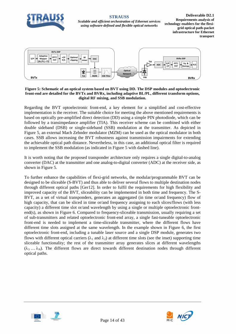
Figure 5: Schematic of an optical system based on BVT using DD. The DSP modules and optoelectronic front-end are detailed for the BVTx and BVRx, including adaptive BL/PL, different transform options,
digital RF mixing, and SSB modulation.
Regarding the BVT optoelectronic front-end, a key element for a simplified and cost-effective implementation is the receiver. The suitable choice for meeting the above mentioned requirements is based on optically pre-amplified direct detection (DD) using a simple PIN photodiode, which can be followed by a transimpedance amplifier (TIA). This receiver scheme can be combined with either double sideband (DSB) or single-sideband (SSB) modulation at the transmitter. As depicted in Figure 5, an external Mach Zehnder modulator (MZM) can be used as the optical modulator in both cases. SSB allows increasing the BVT robustness against transmission impairments for extending the achievable optical path distance. Nevertheless, in this case, an additional optical filter is required to implement the SSB modulation (as indicated in Figure 5 with dashed line).
It is worth noting that the proposed transponder architecture only requires a single digital-to-analog converter (DAC) at the transmitter and one analog-to-digital converter (ADC) at the receiver side, as shown in Figure 5.
To further enhance the capabilities of flexi-grid networks, the modular/programmable BVT can be designed to be sliceable (S-BVT) and thus able to deliver several flows to multiple destination nodes through different optical paths [Ger12]. In order to fulfil the requirements for high flexibility and improved capacity of the BVT, sliceability can be implemented in both time and frequency. The S-BVT, as a set of virtual transponders, generates an aggregated (in time or/and frequency) flow of high capacity, that can be sliced in time or/and frequency assigning to each slices/flows (with less capacity) a different time slot or/and wavelength by using a single or multiple optoelectronic front-end(s), as shown in Figure 6. Compared to frequency-sliceable transmission, usually requiring a set of sub-transmitters and related optoelectronic front-end array, a single fast-tuneable optoelectronic front-end is needed to implement a time-sliceable transmitter, where the different flows have different time slots assigned at the same wavelength. In the example shown in Figure 6, the first optoelectronic front-end, including a tunable laser source and a single DSP module, generates two flows with different optical carriers (λ1 and λ2) at different time slots (see the inset) supporting time sliceable functionality; the rest of the transmitter array generates slices at different wavelengths (λ3 … λN). The different flows are direct towards different destination nodes through different optical paths.
DACTIA
PIN
ADC
MZMTLS
BVTx DSP
BVRx DSP S/PAdaptiveMapper
(BL/PL) +TS
IFFT/FHT
+CPP/S
S/P-CP
FFT/FHT P/SEq. &
Demap.
OpticalNetwork
SSB Filter
RFmixer
BVTx BVRx
Optimalclipping

STRAUSS Scalable and efficient orchestration of Ethernet services
using software-defined and flexible optical networks
Deliverable D2.1 Requirements analysis of
technology enablers for the flexi-grid optical path-packet
infrastructure for Ethernet transport
Page 15 of 43
Figure 6: Time/frequency S-BVTx generating multiple flows/slices at different time slots and wavelengths routed towards different destination nodes, equipped with BVRx.
A preliminary version of a cost-effective hybrid time/frequency S-BVT, based on DD-OFDM and low complex FHT processing, has been experimentally investigated in a realistic environment emulating a photonic mesh network [Fab14]. It has been demonstrated that the proposed S-BVT is capable of concurrently serving multiple destination nodes at variable bit rate, while switching between different wavelengths / time slots. BPSK and 4ASK/4PAM modulation formats were assessed, running at 5 Gbaud, and achieving up to 2 bit per symbol for different time slots. Its performance was experimentally evaluated in the 4-node ADRENALINE network testbed, covering paths ranging from 50 km to 185 km. Specifically, three different scenarios were tested, all based on the experimental setup shown in Figure 7 and detailed in [Fab14].
Figure 7: DSP schemes of (a) the transmitter and (b) the receiver. (c) Experimental setup. (d) Network scheme.
In scenario 1 a standard integrable tunable laser assembly (iTLA), was used as a tuneable lightwave source (TLS) at the transmitter, with a burst time duration limited to 30 ms. The TLS was kept switching between channels 32 and 33 (1551.72 nm and 1550.92 nm), and the transmitter output was injected into node N1 of the ADRENALINE testbed. There, two lightpaths were simultaneously established for serving two different locations of the network. Precisely, channel 32 was routed
node-1
node-N
OpticalMod.
DACDSP
λN
λ3
BVRx
BVRx
λ1-λm
λN
TLS
TLS
DACDSP
OpticalMod.
OpticalNetwork
Aggregator
. . .
λ1 λ1
λ1 λ1λ2
node-2
BVRx
OpticalMod.
DACDSP
TLS
λ3
λ3 λNλ1 λ2
Time/Frequency S-BVTx
. . .
(a)
(b)
(c)Vi
Vi
VoVo
Be Bg
Bo
λo
λo+fcλo-fc
data
data
(d)

STRAUSS Scalable and efficient orchestration of Ethernet services
using software-defined and flexible optical networks
Deliverable D2.1 Requirements analysis of
technology enablers for the flexi-grid optical path-packet
infrastructure for Ethernet transport
Page 16 of 43
through the link between N1 and N4, covering a distance of 50 km (case 1); while channel 33 was routed towards node N3, passing through node N2, giving a path length of 185 km (case 2). According to the results [Fab14], for a short distance path (case 1), both modulation formats could be transmitted successfully; whereas for the longer path the format was limited to BPSK, and the granularity only based on the time slicing.
In scenario 2, the TLS source was substituted by an array of lasers, set at different wavelengths, which were properly combined by a 10 ns PLZT optical switch for generating the desired TDM bursts. With this implementation, the duration of each burst was reduced down to 400 µs. An optical amplifier was set at the output of the transmitter, for compensating the increased insertion losses due the fast optical switch. For this case, a power penalty of less than 1.5 dB was obtained with respect to the measurements in back to back obtained for scenario 1. For network cases 1 and 2, BPSK behaviour was similar to scenario 1. For case 2, a correct 4PAM transmission could not be achieved, limiting this modulation format to be used for shorter paths.
Figure 8: Scheme of the sliceable transmitter and the first node of the network for implementing the hybrid wavelength/time-switching networking (scenario 3).
For scenario 3, the target was to demonstrate the possibility of integrating this last approach of sliceable transceiver with a hybrid wavelength/time routed network. To that extend, a second fast switch (SW2) was integrated into the node N1 of the ADRENALINE testbed. This switch was controlled to route the traffic flows at different time slots towards different destinations in the network. Furthermore, a 10 km fibre spool was placed after the transmitter in order to emulate a first optical link (hop) prior to that node, as shown in Figure 8. The switching period of SW1 was 800 µs, while the signal controlling SW2 had a period of 1.6 ms. This variable timing control of the switches allows directing single or multiple time slots with arbitrary modulation formats to different destination nodes; i.e. the transceiver was able to transmit mixed BPSK/4PAM signals to different end nodes. Experiments for scenario 3 show that a correct 4PAM transmission could be achieved only for the first hop path (after passing SW2), while BPSK could be transmitted successfully to both the two possible destinations.
PC
λ1
λ2
TL1
TL2
FastopticalSW 1
FastopticalSW 2
Tunebaletransmission
Network switching
DSP + AWG
MZM
Network
FPGA
Destination 1
Destination 2
delayed δ+
Fast switchingfor generating
multiwavelength
carriers
TriggeringAWG
Fast switchingfor networking
OXC2N1

STRAUSS Scalable and efficient orchestration of Ethernet services
using software-defined and flexible optical networks
Deliverable D2.1 Requirements analysis of
technology enablers for the flexi-grid optical path-packet
infrastructure for Ethernet transport
Page 17 of 43
4.1.2 Real-time OFDM Transmitter
While the implementation in the previous subsection concerns transmission over real optical fibre channels but use off-line digital signal processing, in this subsection a real-time OFDM transmitter is described. The project considers also real-time implementation of critical subsystems to ensure that industry can implement the investigated schemes finally using state-of-the-art analogue and digital components. The real-time OFDM transmitter can give service up to 1024 slices in parallel and enables the use of bit and power loading. The highest supported modulation format is 16-QAM. That enables a maximal achievable gross data rate of 64 Gbit/s at a sample rate of 16 GS/s.
Real-time implementation
For the realization of the real-time OFDM transmitter a single Virtex 6 XC6VHX565T was used to generate the in-phase (I) and quadrature (Q) signal for the two high-speed MICRAM DACs. Figure 9 illustrates the implemented functionality in the FPGA (Field Programmable Gate Array)-based transmitter. The frame generator block generates frames for the OFDM transmitter formed by a header containing the bit loading information and a payload with random data. Moreover, the frame generator easily allows the insertion of user specific pilot tones. The bit loading information is first extracted and stored to be applied on the following random data at the mapping block. The supported modulation formats are BPSK, QPSK and 16-QAM. The subcarriers can also be left unmodulated by setting the signal to zero. A training sequence of 20 OFDM symbols is sent periodically every 192 symbols for frame synchronization and channel estimation at the receiver. Power loading is done on all subcarriers before the 1024-point IFFT to adapt the subcarriers amplitude. This stage consists of multiplying the subcarriers by real-valued power coefficients. After the 1024-point IFFT, the complex OFDM samples are scaled and clipped to be 5 bit wide, both real and imaginary parts, due to the limited numbers of serial IOs. Then a cyclic prefix of 64 OFDM samples is inserted at the beginning of every OFDM symbol. Finally the data structure is adapted to the format required by the DAC interfaces which expect 128 parallel complex samples.
Figure 9: Implemented functionality in the FPGA-based real-time OFDM transmitter
In the following subsections, the challenges faced during the development of the real-time OFDM transmitter are described as well as the trade-off made.

STRAUSS Scalable and efficient orchestration of Ethernet services
using software-defined and flexible optical networks
Deliverable D2.1 Requirements analysis of
technology enablers for the flexi-grid optical path-packet
infrastructure for Ethernet transport
Page 18 of 43
Highly parallel signal processing
FPGA-based signal processing is an attractive option for real-time signal processing implementation in networks. However, despite its clock speed of hundreds MHz, data throughputs of several tens Gbit/s and much higher can be achieved by parallel signal processing [Gid14]. For a given target throughput, the required clock speed decreases proportionally to the number of samples processed in parallel. At the same time, the FPGA resource consumption increases proportionally to the parallelism grade. Both high clock speed (≥250 MHz) and high FPGA resource consumption turn real-time implementation into a challenging task. The networks targets translate into ambitious design requirements. Resource-consuming implementation is needed due to the IFFT size and high data throughputs to be processed for the high aggregate data rate. From the hardware development point of view and in order to minimize the complexity, a tradeoff between feasible clock speed and limited resource consumption has to be made.
In such a high performance application pipelined architectures are of vital importance to meet the FPGA timing requirements (clock speed). Since pipelining consists of adding intermediate buffer stages to break combinatorial paths and reduce processing delays (increase clock speed), it will also impact on the overall resource consumption. The likely congested resulting design will need optimization for a successful and efficient implementation. This consists of proper coding, careful description of timing requirements that will be passed to the design software as constraints, as well as manually placing blocks of logic in the FPGA.
The most demanding task in real-time OFDM is the implementation of the IFFT. It consists basically of multiplications and additions. The required number of multiplications will determine the concrete 1024-point IFFT structure to be implemented. This structure is defined by the complex parallelism P and it combines P blocks performing a P-point IFFT and one 1024/P-point IFFT, as shown in Figure 10. A 1024-point IFFT with a complex parallelism of 64 already occupies 72% of the available dedicated multipliers (DSP slices). Since P can only take values that are power of two, the next structure would present a parallelism of 128 which would relax the working speed to the half but would require more multiplications than available DSP slices in the target FPGA. For this reason a complex parallelism of P=64 was chosen.
Figure 10: 1024-point IFFT hardware structure
In order to guarantee a minimal aggregate data rate of 40+ Gbit/s and keeping in mind the design challenges derived from high clock speeds, frequency was set to 250 MHz resulting in a sample rate

STRAUSS Scalable and efficient orchestration of Ethernet services
using software-defined and flexible optical networks
Deliverable D2.1 Requirements analysis of
technology enablers for the flexi-grid optical path-packet
infrastructure for Ethernet transport
Page 19 of 43
of 16 GS/s at a parallelism of 64. The highest supported modulation format is 16QAM which enables a maximal gross data rate of 64 Gbit/s. The complex parallelism P=64 yields a matrix-like data structure forming the 1024-sample block that is processed in the real-time OFDM transmitter. In this (complex) matrix one axis is formed by (double) P=64 parallel buses and the other axis consists of time slots during which the content of these buses changes. That means that for a given physical point in the real-time design, e.g. the IFFT input, the information of an OFDM block is completely available after 16 clock periods (1024/64 = 16) as depicted in Figure 11. This matrix data structure is flexible and has a great potential. The width of the P complex buses varies with the signal processing flow. This width goes from 3 bits at the output of the mapping block to 18 bits at the 1024-point IFFT output.
Figure 11: Matrix-like data structure at the 1024-point IFFT input
The subcarrier index distribution also varies. For instance, Figure 11 shows the data structure at the 1024-point IFFT input where the first 64 subcarriers are available at the same time in the parallel buses during the first time slot. That is actually the natural data structure and is also the expected index distribution that DACs and ADCs interfaces usually present. Nevertheless, this index distribution appears transposed at the 1024-point IFFT output as shown in Figure 12, where the first 16 samples are available in one single bus one clock period after the other. This requires a precise flow control in order not to lose the meaning of the real-time data structure. But despite the increased control complexity, the resulting data structure can be adapted and scaled to new system requirements by changing P (modifying the hardware replication) or changing the required number of time slots (modifying mainly the real-time flow control) resulting in an scalable real-time OFDM implementation.

STRAUSS Scalable and efficient orchestration of Ethernet services
using software-defined and flexible optical networks
Deliverable D2.1 Requirements analysis of
technology enablers for the flexi-grid optical path-packet
infrastructure for Ethernet transport
Page 20 of 43
Figure 12: Matrix-like data structure at the 1024-point IFFT output with transposed subcarrier index distribution
Flexible OFDM implementation
In order to fully exploit OFDM flexibility a real-time implementation should include bit and power loading. We present a flexible real-time OFDM transmitter where the hardware design complexity has been minimized. With a complex parallelism of 64, the mapping block in Figure 9 actually consists of 64 parallel mappers. Each of them supports BPSK, QPSK and 16QAM and can also leave a subcarrier unmodulated by setting the signal to zero. With a matrix-like data structure as depicted in Figure 11, every mapper processes 16 different subcarriers as depicted in Figure 13. In order to support all possible bit-loading mask combinations, the frame generator block always generates 4 bits per subcarrier, since the highest supported modulation format is 16QAM. In this way the input width of every mapper is fixed to 4 bits for every subcarrier avoiding a huge amount of logic to support dynamic input bus width variations for the 64 mappers. In M-ary modulation schemes (16QAM, QPSK and BPSK), log2 (M) bits are mapped (4, 2 and 1, respectively) into a complex symbol. In the 4-bit wide mapper input word, the log2 (M) bits are located in the less significant positions. The rest are set to zero before the mappers apply the appropriate constellation. Actually, the interface to the physical layer (frame generator) presents a constant data rate. The dynamic bit rate distribution within the subcarriers is a task that will be implemented in the media access control (MAC) layer. The applied bit loading mask can be defined by the user.

STRAUSS Scalable and efficient orchestration of Ethernet services
using software-defined and flexible optical networks
Deliverable D2.1 Requirements analysis of
technology enablers for the flexi-grid optical path-packet
infrastructure for Ethernet transport
Page 21 of 43
Figure 13: Realization of variable bit loading
Power loading is also implemented before the 1024-point IFFT. This stage consists of 64 parallel multipliers. Since the subcarriers transport complex symbols, each multiplier actually consists of two real-valued multiplications. The real-valued amplitude coefficients can also be defined by the user for every single subcarrier.
DAC bit resolution
Another important limitation of high-speed signal processing is the DAC bit resolution. A 6 bit resolution DAC would require 24 high-speed serial transceivers (GTX) for interfacing the FPGA in order to achieve very high sample rates. Every bit is sent through 4 GTX transceivers whose data are then multiplexed on the DAC side to rebuild the original sequence. In this way the GTX transceivers can work four times slower than the target sample rate. This makes possible the application of such high-speed data converters in real-time signal processing systems. For the realization of the real-time OFDM transmitter a single Virtex 6 XC6VHX565T was used to generate the I- and Q-signals for the two high-speed MICRAM DACs. That is only feasible if the DACs are driven with 5 bits. Since there are 40 available GTX in the FPGA, 20 GTX (20/4 = 5 bits) can be used to interface each DAC. Despite the reduced resolution of 5bits, the highest feasible modulation format is still 16-QAM. In this way, system performance is not degraded and still meets the networks target data rate. Moreover, in spite of increasing the complexity, the use of a single FPGA results in a compact and resource-efficient real-time OFDM transmitter since no redundant signal processing has to be implemented. The real-time OFDM transmitter presented here consumes 27% of the available slice registers, 38% of the available LUTs (Look-Up-Table), 72% of the available DSP slices and 100% of the available GTXs.
Experimental Setup
Figure 14 depicts the experimental setup. The FPGA-based real-time optical OFDM transmitter performed the OFDM signal processing presented in the previous section and includes the interface to two DACs yielding the I- and Q-signals in real-time. An analog IQ modulator is being used to generate a real-valued electrical signal to drive a MZM in order to generate the optical OFDM waveform. After amplification and optical filtering (to generate a single side-band signal) the signal passed a SSMF link. The optical signal is directly detected using a PIN photodiode and a TIA at the receiver. The received signal is recorded using a real-time oscilloscope and offline processed.

STRAUSS Scalable and efficient orchestration of Ethernet services
using software-defined and flexible optical networks
Deliverable D2.1 Requirements analysis of
technology enablers for the flexi-grid optical path-packet
infrastructure for Ethernet transport
Page 22 of 43
Figure 14: Experimental setup including real-time transmitter, and electrical and optical components
By the time the field trial was about to start instabilities were observed in the real-time sender operation. The problem was related to the FPGA clock speed and only appeared when the system was clocked at the maximal supported speed of 16 GHz. At lower frequencies it was stable. In order to get reliable results, the tests were performed at a sampling rate of 12 GS/s. Meanwhile, the problem was identified and solved. Further tests are planned to characterize the real-time OFDM transmitter at full speed.
Experimental Results
First, we investigated the real-time transmitter in an electrical back-to-back setup. A data rate of 48 Gbit/s was achieved at a sample rate of 12 GS/s where 999 subcarriers were modulated with the highest modulations order of 4 bit/symbols (16QAM). The remaining subcarriers were turned off. In order to achieve a BER below 3.8⋅10-3 in the optical back-to-back setup the maximum modulation order was reduced to 2 bits/symbols (QPSK) for 999 subcarriers giving 23.4 Gbit/s data rate at 12 GS/s. This rather significant drop in performance compared to the electrical back-to-back performance can be explained partly by the IQ imbalance of the analogue IQ-mixer. For the transmission over the 36 km installed fibre the bit loading had to be reduced further. Here a mixture of QPSK (256 subcarriers) and BPSK (748 subcarriers) was used giving a total transmission rate of 14.7 Gbit/s. We expect to increase the data rates significantly by using the optimized 16 GS/s capable design as explained earlier. This includes also a redesigned receiver using a second IQ-mixer to down-convert I and Q to the baseband together and overall a better IQ imbalance compensation to improve the fidelity of the transmission and thereby the throughput performance further.
4.1.3 DMT Transceiver
Network traffic is growing exponentially. Especially Ethernet traffic is becoming dominant for client- and line-side traffic. Total bandwidth of the network is predicted to be beyond 1Tb/s by 2015 [ieee802-1]. 100Gigabit Ethernet and beyond is indispensable to realize cost and energy efficient networks. In these circumstances, IEEE802.3 has started the discussion of standardization of 400GbE from 2013.
DFB MZM
IQ
Optical BP0.35nm
EDFA
LO
Optical BP0.35nm
EDFA
PIN&TIA
24GHz
InstalledFibre
Q I
Real-timeTx
Real-timeTx
Back-to-Back
13dBm1550nm

STRAUSS Scalable and efficient orchestration of Ethernet services
using software-defined and flexible optical networks
Deliverable D2.1 Requirements analysis of
technology enablers for the flexi-grid optical path-packet
infrastructure for Ethernet transport
Page 23 of 43
Figure 15: Scope of IEEE Ethernet standardization [ieee802-1]
In its early stage, the 400GbE standardization targeted the link distances of 500 m, 2 km, and 10 km for SMF transmission by focusing on the intra-building application [ieee802-2]. However, there has been a strong demand for beyond 100GbE connection for inter-building applications which requires the link distance of up to 40 km. [ieee802-3][ieee802-4].
Figure 16: Requirements on link distance of 400GbE [ieee802-4]
Meanwhile, since, it is difficult to achieve the data rate of 400 Gb/s on single wavelength channel due to the limited bandwidth of current opt/electronics. , various architectures have been proposed for 400GbE by using multiple wavelength channels [ieee802-5][ieee802-6]. Consequently, a major interest there was how to increase the bit rate per wavelength to avoid the cost-inefficiency of the parallel implementation in the wavelength domain while achieving the extended link distance of 40km. Currently, 100 Gb/s per wavelength transmission by employing highly spectrum-efficient advanced modulation format, such as DMT or pulse amplitude modulation (PAM) [ieee802-3], gathering much attention as promising solution for 400GbE.

STRAUSS Scalable and efficient orchestration of Ethernet services
using software-defined and flexible optical networks
Deliverable D2.1 Requirements analysis of
technology enablers for the flexi-grid optical path-packet
infrastructure for Ethernet transport
Page 24 of 43
(a) 56Gbps x 8λconfiguration [ieee802-5]
(b) 116Gb/s x 4λ configuration[ieee802-6]
Figure 17: 400GbE transmission architecture
The DMT technology is an OFDM based multicarrier modulation format, which is widely used in digital subscriber line (DSL) system from its high spectral efficiency and simple configuration. Optical DMT technology transmits data only by an intensity domain of the optical carrier signal with a single-electrode modulator, and can be directly detected by a single photo detector. Figure 18 shows the concept of the DMT technology. The DMT signal comprises a group of subcarriers and the modulation format of each subcarrier is determined from the transmission characteristic of each subcarrier. The transmission characteristic is obtained by transmitting the probe signal beforehand and/or sending pilot subcarriers together with data subcarriers A major advantage of DMT against other higher-order modulation techniques, such as PAM, is its robustness to the frequency selectivity of channels. The 100Gb/s-class intensity modulation systems over tens of kilometres SMF suffer from the frequency selectivity such as due to poor frequency responses of RF devices and/or chromatic dispersion of SMF, and these impairments can be vary depending on transponders as well as the link distances. Optical DMT can efficiently adapt to such variation in the digital domain and has potential to realize the robust 400GbE over 40 km SMF [ieee802-6].
Figure 18: Discrete Multi-Tone technology

STRAUSS Scalable and efficient orchestration of Ethernet services
using software-defined and flexible optical networks
Deliverable D2.1 Requirements analysis of
technology enablers for the flexi-grid optical path-packet
infrastructure for Ethernet transport
Page 25 of 43
The specifications of DMT transceiver for beyond 100GbE networks is summarized in Table 1.
Items Parameters Values Transmission characteristics Data rate per wavelength ≤ 100 Gb/s
Transmission distance ≤ 40 km Number of wavelength 4 Target BER 1 x 10⁻³
Interface Optical transmitter output optical DMT signal Optical receiver input optical DMT signal Network Controller IF Ethernet
Controllable parameters from Network Controller
Number of Subcarriers 128, 256, 512, 1024, 2048 Adaptive modulation policy Link distance, bandwidth
demand, QoS (Predetermined via Network controller)
Monitor parameters to Network Controller
SNR, BER, Data rate
Table 1: Specifications of DMT transceivers for beyond 100GbE
The experimental demonstration of a 448 Gb/s DMT transmission over 30 km single mode fibre was reported at OFC 2014 [Tan14].
4.1.4 Superchannel signal generator with single carrier modulation
The superchannel signals provide higher “per-channel” data rate, to avoid electronic bottlenecks and make wavelength management easier. The SC signals can provide total capacity up to Tbit/s for future Terabit Ethernet with limited bandwidth devices. Due to the compact spectrum allocation, the superchannel signals have higher spectrum efficiency. In addition the superchannel signals also will increase efficiency in digital signal processing due to the shared characteristics of carriers. To provide system flexibility and to accommodate different application scenarios, key parameters of the BVT, related to the SC signals, are required to be adjusted (programmed) such as the number of carriers, the channel spacing, the bit rate and the modulation format of each carrier. Thus, the occupied optical bandwidth, the total capacity and the spectral efficiency of the SC signals can be selected appropriately. Figure 19 shows a typical configuration of SC signals with single carrier modulation technologies. In here, several carriers supporting different modulation format signals are assembled to create SC signals.

STRAUSS Scalable and efficient orchestration of Ethernet services
using software-defined and flexible optical networks
Deliverable D2.1 Requirements analysis of
technology enablers for the flexi-grid optical path-packet
infrastructure for Ethernet transport
Page 26 of 43
Figure 19: Super channel signals with several subcarriers and different modulation formats
Based on the aforementioned SC signal description, the key requirements of programmable S-BVT are shown as follows:
[REQ-SCG-1] The minimum channel spacing for SC signals should be adjustable to suit both flexi-grid and fixed grid DWDM networks. For example, it can be adjusted from 37.5 GHz (Nyquist DWDM) to 50 GHz (DWDM).
[REQ-SCG-2] The modulation format for each carrier should be also programmable. All the available transmitter technologies can be adopted to modulate each carrier. For the single carrier modulation, the modulation format programmability enable the SC signals to handle the over-filtering effects in flexi-grid optical networks: The central subcarriers can use some higher order modulation formats, while the edge subcarriers can adopt some filter-tolerant modulation format.
[REQ-SCG-3] To facilitate the signal processing, each carrier in the SC signal could carry signals with the same bandwidth. However, high-baud rate signals will be required as well, demanding a large bandwidth, as shown in Figure 21.
[REQ-SCG-4] To achieve more compact spectrum allocation, high wavelength stability of each carrier is required, especially when using Nyquist WDM signals. Thus, all the SC carriers should be generated from a single laser, which will make all the carriers experience same wavelength drifting.
[REQ-SCG-5] The total capacity should be programmable for variable application scenarios.
Using a modulation-format adaptable transmitter, we successfully demonstrated the generation of 8-carrier superchannel signals. The experimental setup is shown in Figure 20. The OPS-OCS interface card, implemented using high performance FPGA (HTG Xilinx V6 PCIE board), receive Ethernet traffic using multiple 10GE SPF+ modules, and then process and groom the traffic to drive a sliceable, programming BVT.

STRAUSS Scalable and efficient orchestration of Ethernet services
using software-defined and flexible optical networks
Deliverable D2.1 Requirements analysis of
technology enablers for the flexi-grid optical path-packet
infrastructure for Ethernet transport
Page 27 of 43
Figure 20 Experimental setup of superchannel signal generation
The groomed and classified ingress traffic from multiple access links is then assigned to different egress ports. A 2:1 multiplexer is used to multiplex four data streams from four egress ports to 20 Gbit/s electrical signals. Then the achieved 20 Gbit/s electrical signals drive an IQ modulator to modulate 8 external cavity lasers (ECLs) to obtain 20 Gbaud QPSK signals. The CWs of 8 ECLs are tuned within a 100 GHz grid for 20Gbaud signals. Then a polarization multiplex (PM) stage is used to achieve 20 Gbaud PM-QPSK signals. Part of the 20 Gbaud QPSK signals is launched into a QAM16 emulator (Kylia) to achieve 20 Gbaud 16QAM signals. Again, a PM stage is used to double the spectral efficiency to achieve 20 Gbaud PM-16QAM signals.
Then, the generated QPSK and 16QAM signals are launched into a 4:1 WSS (Finisar Waveshaper) via a large-port-number beam steering fibre switch (polatis) for future re-configurability. By choosing either PM-QPSK modulation format or PM-16QAM modulation format, an 8-subcarrier SC signals are obtained with modulation format re-configurability for each subcarrier. Fig.4 shows the spectrum of the generated 8-subcarrier SC signals with 16QAM modulation in channel 3, 5, 7, and QPSK modulation in other subcarriers (label as SC1). By adopting different modulation formats and different quantity of subcarriers, we obtained SC signals with capacity from 80 Gbit/s up to 1.28 Tbit/s.

STRAUSS Scalable and efficient orchestration of Ethernet services
using software-defined and flexible optical networks
Deliverable D2.1 Requirements analysis of
technology enablers for the flexi-grid optical path-packet
infrastructure for Ethernet transport
Page 28 of 43
Figure 21 Optical spectrum of the two SC signals: SC1: reconfigurable SC signals (ch3, 5, 7: 16QAM; Other: QPSK) in 100GHz Grid; SC2: SC signals with QPSK in 40GHz grid
The second SC signals are achieved by using another four 10 Gbit/s data streams from egress output ports to drive a dual polarization IQ modulator to obtain 10 Gbaud PM-QPSK signals. A tunable mode-locked laser (TMLL) based optical comb generator is used to generate subcarriers with 10 GHz channel spacing. Followed by a delay interferometer and an optical filter, 8 subcarriers are selected with 40 GHz channel spacing. The generated SC signals are also feed into a 1:4 WSS (Finisar Waveshaper) for re-configurability in different application scenarios. The spectrum of the generated SC signals is shown in Figure 21.
4.2 Flexi-grid OCS & OPS nodes and interface
4.2.1 Flexible/adaptable optical nodes for flexi-grid DWDM networks
Optical Ethernet fundamentally changes the way networks are being designed, built and operated by creating a new networks solution that expends the boundaries of the LAN environments to encompass the MAN and WAN. In STRAUSS project, a direct connection link between OPS-based metro networks and flexi-grid OCS-based core network will be provided for cross domain Ethernet services. The evolution will bring new challenge to the optical nodes design.
Take into consideration the complex nature of the Ethernet traffic, the optical node needs to cope with an increasingly heterogeneous and dynamic traffic environment than the common long-haul core networks: 1) large optical switching granularity that vary from tenths of Gb/s to Tbit/s, 2) connection hold times that range from quasi-permanent to hour-long or even shorter timescales, which lead to rapid connection reconfiguration in short time scale, and 3) mixed line rates signals with different modulation formats and thus variable occupied bandwidth. Clearly, the optical node with static structure can’t provide such flexibility and reconfigurability.

STRAUSS Scalable and efficient orchestration of Ethernet services
using software-defined and flexible optical networks
Deliverable D2.1 Requirements analysis of
technology enablers for the flexi-grid optical path-packet
infrastructure for Ethernet transport
Page 29 of 43
Thus new flexi-grid optical nodes should be proposed to enable bellowing requirements:
[REQ-OCS-1] Flexible optical switch
As the flexi-grid optical networks will adopt mixed line rate signals, flexible switching will be required, including superchannel band switching, arbitrary spectrum switching, and sub-wavelength switching. The optical node should have the capability to handle signals with a large range of granularity, for example, fibre to fibre, super-channel signals to super-channel signals, wavelength to wavelength. By using optical fast switching, synchronized sub wavelength switching can be supported in the optical nodes. Reconfigurable WSS will be one of the key device in flexi-grid optical networks.
[REQ-OCS-2] Adaptable ROADM structure
For different signals, the optical node should be capable to provide different ROADM structure under different network situations. That means the ROADM structure can adapt different structures, for example, broadcast-and-select, route-and-select, CDC ROADM. With the available hardware resources, ROADM with different scale will be synthesized according to the requirements.
[REQ-OCS-3] Network resource optimization
The same type of network resource can be rebalanced to optimize the network resource usage. In order to do this, adaptable node architecture will be required.
[REQ-OCS-4] Flexible invest management
The optical nodes with static structure are typically dimensioned based on peak hour traffic with considerable over-provisioning. The scale and cost should be decided at the construction stage. For the flexi-grid optical node, a more flexible invest management is needed to deploy node scales according to the requirements. A smoothly invest will be favoured by the operator. In addition, the flexible node invest also allow update with new functions gradually, to face the emerging internet applications.
[REQ-OCS-5] Support virtualization layer
The optical node need to fully support the virtualization layer for the considered multi-layer and multi-domain transport network. Good isolation of virtual resources and architectures will guarantee non-disruptive VN operation.

STRAUSS Scalable and efficient orchestration of Ethernet services
using software-defined and flexible optical networks
Deliverable D2.1 Requirements analysis of
technology enablers for the flexi-grid optical path-packet
infrastructure for Ethernet transport
Page 30 of 43
AoD-based flexible modular and scalable optical node
To addressing the aforementioned requirements, we propose a flexible, modular and scalable optical node structure based on Architecture on demand (AoD) concept. The concept of AoD-based flexible, modular and scalable optical node is shown in Figure 22.
Figure 22: Concept of AoD architecture
The network resources, including subsystems and components, are all connected to an optical backplane, which is consisted of a large port-number fibre switch. The input- and output-ports of the entire inventory are managed and controlled by the optical backplane. As shown in Figure 22, the optical nodes consists of several network function subsystems, such as super channel add/drop, fast timing switching, format conversion and layer 2 interface. Some common components used for optical processing, e.g. SSS, power splitters, multiplexer, EDFAs, are not hard-wired like in a static architecture, but can be interconnected together in an arbitrary manner. Thus in principle, the subsystems can be synthesized under request.
In the AoD node, the optical backplane will configure the cross-connections of the inputs, modules and outputs to deliver on-line diverse and reconfigurable architectures (e.g. broadcast-and-select, wavelength-modular, spectrum-routing, switch-and-select etc.). The reconfigurable structure of the optical nodes means synthetic node architectures can be dynamically created involving only the required functionality.
Add/Drop Bank on Demand
ROADMs are key elements in current operators’ backbone networks. Based on the AoD concept, we propose an add/drop bank on demand (ADoD). Figure 23(a) shows an example of a synthesized ADoD where an optical backplane interconnects k fibres from/to each degree (i.e. from/to WSSs at each input/output), different modules and k×m transmitters and receivers. The optical backplane

STRAUSS Scalable and efficient orchestration of Ethernet services
using software-defined and flexible optical networks
Deliverable D2.1 Requirements analysis of
technology enablers for the flexi-grid optical path-packet
infrastructure for Ethernet transport
Page 31 of 43
is implemented with a beam-steering optical switch having just 0.5 dB insertion loss. Our proposed ADoD offers many advantages over other previously referred add/drop bank (ADB) proposals. In particular, i) since resources are not assigned to a specific degree of the ROADM, different modules can be shared among different degrees; ii) ADoD presents high availability because module failures can be addressed by swapping the faulty module with an operational module or by constructing an alternative ADoD fulfilling the same requirements without the faulty module; iii) ADoD offers high upgradability, since new modules can be plugged to the optical backplane without compromising links in operation; iv) in ADoD different modules can be installed according to a pay-as-you-grow basis or technological developments; v) the reconfigurable nature of ADoD provides intrinsically CDC capabilities. In addition, ADoD is aligned with several research trends driven by carriers’ requirements on network functions virtualization (NFV), in which a common hardware infrastructure can play different roles according to service requirements.
Figure 23(b) shows an example of a synthesized ADoD (only drop direction) with k=N=3 (i.e. a ROADM of degree 3 with 1×6 WSSs at the express bank) where two signals from each input are dropped. Note that thanks to the R&S structure, optical filtering is not required in case of non-coherent signals. In Figure 23(c), the number of dropped signals from degrees 1 and 2 can be handled by direct backplane cross-connections, but a WSS module is required since the number of dropped signals exceeds k from degree 3.
Figure 23: (a) Synthesized ADoD; (b) and (c) ADoD examples
Scalability of AoD-based optical nodes
As the AoD optical nodes need a large-port-number optical backplane to manage the interconnection of the subsystems and components, the scale of the optical backplane will affect the whole optical node scales. Currently, the maximum ports of available switch are up to 320×320 ports. To improve the scalability of the AoD nodes, several methods can be done to provide large scale optical node.
a) Integrated subsystem to a function module.
No dynamic interconnections will exist in the function module. The optical backplane will only manage the interconnection of the function modules. In this way, the required input ports of the optical backplane optical ports can be dramatically decreased.
b) Interconnect several large-port number optical switches to realize large scale optical backplane.

STRAUSS Scalable and efficient orchestration of Ethernet services
using software-defined and flexible optical networks
Deliverable D2.1 Requirements analysis of
technology enablers for the flexi-grid optical path-packet
infrastructure for Ethernet transport
Page 32 of 43
Figure 24 Backplane composition alternatives based on multiple switches
Figure 24(a) depicts the first composition, denoted as “Unidirectional”, to interconnect several fibre switches. 𝑦𝑈 optical fibre switches are connected in a unidirectional fashion with k ports. In more detail, the N input ports of AoD are connected to N inlets of the first switch. Then, N outlets of the first switch are connected to N inlets of the second switch. This process is repeated until N outlets of the switch 𝑦𝑈 − 1 are connected to N inlets of the switch 𝑦𝑈𝑦𝑈. Finally, N outlets of the switch 𝑦𝑈 are associated to the N output ports of AoD. By construction, optical signals are constrained to pass through all the optical backplane switches. This configuration supports a number of cross connections 𝑋𝑈 equal to
𝑋𝑈 = 𝑦𝑈𝑘 − 𝑁(𝑦𝑈 − 1)
Where the second term of the subtraction evaluates the number of ports dedicated to the interconnection between switches. Therefore, the subtracted ports are not available for the modules to be connected. Note that for this backplane composition the number of backplane switches 𝑦𝑈𝑦𝑈 must be set in a resource dimensioning study carried out before AoD is deployed and used. Indeed, once 𝑦𝑈 is set and AoD is operating, the connection of additional backplane switches would compromise the already established optical links.
Figure 24 (b) depicts the second composition, denoted as “Expandable”, where 𝑦𝐸 optical backplane switches of k ports are bidirectionally connected. More in detail, the N input and output ports of AoD are are connected to the first optical backplane switch. In addition, N outlets of the first switch are connected to N inlets of the second switch and N outlets of the second switch are connected to N inlets of the first switch. This process is repeated until N outlets of the switch 𝑦𝐸 − 1 are connected to N inlets of switch 𝑦𝐸 and N outlets of the switch 𝑦𝐸 are connected to N inlets of the switch 𝑦𝐸 −1.

STRAUSS Scalable and efficient orchestration of Ethernet services
using software-defined and flexible optical networks
Deliverable D2.1 Requirements analysis of
technology enablers for the flexi-grid optical path-packet
infrastructure for Ethernet transport
Page 33 of 43
Once the AoD is operating, this composition uses the optical backplane switches in an incremental manner since switches in the first stages of optical backplanes are the first ones to be completely used. Therefore, this Expandable backplane composition permits to adapt 𝑦𝐸 to the traffic request and the connection of additional backplane switches without compromising already established optical links through AoD. This configuration supports a number of cross connections 𝑋𝐸 equal to
𝑋𝐸 = 𝑦𝐸𝑘 − 2𝑁(𝑦𝐸 − 1).
Experimental demonstration of AoD networks
The experimental demonstration consists of four architecture-on-demand (AoD) based optical nodes, using several beam-steering fibre switches (polatis). The developed reconfigurable SC transmitters are deployed in Node 1 and other three EON nodes are connected with Node 1 with different length of fibres to simulate variable optical transmission path and link conditions. All the optical nodes are configured and controlled by the SDN controller.
Figure 25 Flexi-grid optical networks with four AoD-based optical nodes
4.2.2 OPS node and OPS network
In the following subsection the main requirements for the OPS environment are described:
[REQ-OPS-1] 100 Gb/s-class optical packet transport
OPS shall target the data rate of 100 Gb/s and beyond. See [REQ-VIRT-1 D4.1].
[REQ-OPS-2] Sub-wavelength granularity
OPS will provide a sub-wavelength path/slice in time domain on a single wavelength on flexi-grid.
[REQ-OPS-3] Fixed-length Variable-capacity payload
In order to ease buffer scheduling and mitigate void problem in buffer of OPS, an optical packet shall be of fixed-length (FL) but the capacity has to be variable with the fine data granularity of one bit, which is named after FL-VC packet.

STRAUSS Scalable and efficient orchestration of Ethernet services
using software-defined and flexible optical networks
Deliverable D2.1 Requirements analysis of
technology enablers for the flexi-grid optical path-packet
infrastructure for Ethernet transport
Page 34 of 43
[REQ-OPS-4] Multi-modulation formats
A modulation format of data bit shall be adaptively selected so that the FL-VC payload of the packet meets the capacity demand.
[REQ-OPS-5] Payload format adaptation
Packet format should be adaptive to support heterogeneous optical network, e.g., distance-adaptive, QoS-adaptive, etc. Bandwidth variable transponder with sophisticated adaptive modulation algorithms will be a key.
[REQ-OPS-6] Multi-carrier modulation
A modulation format will include a family of OFDM and/or m-array QAM. Particularly, DMT among the OFDM family will be preferable because it does not use coherent detection but it uses direct detection.
[REQ-OPS-7] Transparency in optical packet buffering
In order to maintain the transparency of payload data, OPS buffer shall use fibre delay lines (FDLs). Optical RAM buffer will be out-of-scope.
[REQ-OPS-8] Label and label processing optimization
The information of header shall be represented by the optical label, consisting of serial bits. The label may be processed either electrically or optically, and the bit rate may differ from the one of the payload data.
[REQ-OPS-9] Ethernet frame compatibility
OPS shall be capable of accommodating the Ethernet frame.
[REQ-OPS-10] OpenFlow capability
Flow control shall be introduced in OPS. The flow table shall be translated via OpenFlow controller into the routing table of OPS node. See [REQ-OF-12].
[REQ-OPS-11] OpenFlow agent
OPS node has an interface with OpenFlow agent to update the routing information. See [REQ-OF-10], [REQ-OF-11], and [REQ-OF-14].
4.2.3 Interface between OPS and OCS network
For hybrid optical networks, OPS to OCS interfaces are critical components that enable Ethernet transparency between different network domains. In the OPS-based metro network, the OPS technologies provide a solution to ultrafast, energy- and resource-efficient data aggregation. Then

STRAUSS Scalable and efficient orchestration of Ethernet services
using software-defined and flexible optical networks
Deliverable D2.1 Requirements analysis of
technology enablers for the flexi-grid optical path-packet
infrastructure for Ethernet transport
Page 35 of 43
the aggregated data can transfer through the OCS networks to take full use of its capacity. The key requirements for integrated OPS/OCS interface is listed as bellows:
[REQ-INF-01] Using Ethernet signals as the signal format to realize Ethernet transparency.
[REQ-INF-02] The integrated interface can support variable aggregation ratio to supply the flexible Ethernet signals. Thus the input port of OPS side should be flexible and reconfigurable.
[REQ-INF-03] The integrated interface should provide compatible interface to current available OCS transmitters. For example, the interface should provide data ports, such as the common used SMA ports.
[REQ-INF-04] To support future Terabit Ethernet, several OPS/OCS interface can be group together to realize a high-capacity superchannel signals.
Based on the requirement, an OPS-OCS interface is design and demonstrated based on a high-performance FPGAs. Figure 26 shows the main structure of the OPS to OCS interface. Ethernet package will be adopted through the OPS/OCS interface.
Figure 26: Interface between OPS and OCS networks
The OPS networks will send the signals to the OPS/OCS interface. On the OPS side, the interface will use multiple small form-factor pluggable plus (SFP+) transceivers for communicating over 10 Gb/s DWDM channels for multiplexing the access traffic. Then the OPS/OCS interface based on ultra-high performance optoelectronics platforms of FPGAs will encapsulate the Ethernet packets to OCS networks with grooming and aggregation functions. The interface design will be comprised of a set of essential functions. Figure 27 shows the structure of the interface between OPS and OCS. SDN control block will be built to communicate with the southbound interface of the controller and to store the operation information in a local buffer. Scheduling and control will use the information to coordinate the functions of the OPS/OCS interface. Data processing block is there to parse the ingress traffic of Ethernet frames and their headers, and using the Classification block to buffer the frames for the right output (this will go both ways since the interface is bidirectional). A set of FIFO blocks for store and forward operations is essential from OPS to OCS aggregation and the other way around for disaggregation of multiple streams from the super channels.

STRAUSS Scalable and efficient orchestration of Ethernet services
using software-defined and flexible optical networks
Deliverable D2.1 Requirements analysis of
technology enablers for the flexi-grid optical path-packet
infrastructure for Ethernet transport
Page 36 of 43
Figure 27: Structure of integrated interface between OPS and OCS
On the OCS side, he FPGA platform will be attached to S-BVT modules through high speed RF outputs. The aggregated data streams are feeded into SBVT transmitters through RF outputs.

STRAUSS Scalable and efficient orchestration of Ethernet services
using software-defined and flexible optical networks
Deliverable D2.1 Requirements analysis of
technology enablers for the flexi-grid optical path-packet
infrastructure for Ethernet transport
Page 37 of 43
5 Conclusions
For the realization of the STRAUSS architecture the flexi-grid OCS, the OPS approach and the interface between OCS and OPS are important building blocks.
The flexi-grid OCS needs the software-defined programmable BVT as a key data plane element, which allows flexibly forming super-channel signals, that are routed and switched in optical networks as a whole signal comprised of several subcarriers. Multiple signal slices with variable granularity (including the sub-wavelength level) can be either handled by introducing advanced features in the BVT. Different transceiver designs based on single-carrier technologies and multicarrier technologies, such as OFDM and DMT, are depicted. Further a couple of other technologies, like flexible optical switches, adaptable ROADM structures and the possibility of network resource optimization, are required for the architecture.
For the OPS the general approach with a new photonic layer is specified. The key concept of this photonic layer is to simplify the Ethernet bridging or switching functions as much as possible, by exploiting the inherent nature of photonics and optics such as its high speed, abundant bandwidth, and all-optical processing capability. The intention is to create a new photonic-native data transport protocol, not necessarily emulating the conventional Ethernet protocol, while retaining the interface with the existing protocols at the edges. It is based on fixed length packets with a variable payload. It will use fibre delay lines for buffering purposes.
A possible solution for the interface between the OPS and OCS network is shown. This OPS/OCS interface is based on a ultra-high performance optoelectronics platform of field programmable gate arrays (FPGAs). It will encapsulate the Ethernet packets to the OCS network with grooming and aggregation functions.
First experimental results for specific transceiver solutions, like the 448 Gb/s DMT transmission over 30 km single mode fibre, are also reported. These show the potential of the chosen technologies to meet the target for the Ethernet transport of 100 Gb/s and beyond.

STRAUSS Scalable and efficient orchestration of Ethernet services
using software-defined and flexible optical networks
Deliverable D2.1 Requirements analysis of
technology enablers for the flexi-grid optical path-packet
infrastructure for Ethernet transport
Page 38 of 43
6 References
[Aug13] J.-L. Auge, “Can we use flexible transponders to reduce margins?,” in Optical Fiber Communication Conference and Exposition and the National Fiber Optic Engineers Conference (OFC/NFOEC), 2013, 2013, pp. 1–3. [Cho13] H. Y. Choi, T. Tsuritani, and I. Morita, “Feasibility demonstration of flexible Tx/Rx for spectrum defragmentation in elastic optical networks,” in Optical Fiber Communication Conference and Exposition and the National Fiber Optic Engineers Conference (OFC/NFOEC), 2013, 2013, pp. 1–3.
[Cio13] J. Cioffi, Data Transmission Theory, Chapter 4, Course text for EE379A-B and EE479. Online available: http://www.stanford.edu/group/cioffi/book/
[Doc14] A. Dochhan, L. Nadal, H. Griesser, M. Eiselt, M. Svaluto Moreolo, and J. P. Elbers, “Experimental investigation of discrete multitone transmission in the presence of optical noise and chromatic dispersion,” in Optical Fiber Communication Conference (OFC), 2014, p. Tu2G.7.
[Fab14] J. M. Fabrega, M. Svaluto Moreolo, F. J. Vilchez, B. R. Rofoee, Y. Ou, N. Amaya, G. Zervas, D. Simeonidou, Y. Yoshida, K.-I. Kitayama, “Experimental Demonstration of Elastic Optical Networking utilizing Time-Sliceable Bitrate Variable OFDM Transceiver,” in Proc. OFC, San Francisco, CA (USA), March 2014
[Ger12] O. Gerstel, et al., “Elastic optical networking: a new dawn for the optical layer?,” IEEE Commun. Mag., Vol. 50, s12-s20, Feb. 2012. [Gid14] R. Giddings, “Real-time Digital Signal Processing for Optical OFDM-Based Future Optical Access Networks” J. of Lightw. Technol., vol. 32, no. 4, pp. 553-570, Feb. 2014
[ieee802-1] http://www.ieee802.org/3/400GSG/public/mar13/index.html [ieee802-2] http://www.ieee802.org/3/bs/public/14_05/dambrosia_3bs_01a_0514.pdf [ieee802-3] http://www.ieee802.org/3/bs/public/14_05/nicholl_3bs_01_0514.pdf [ieee802-4] http://www.ieee802.org/3/400GSG/public/14_01/sone_400_01_0114.pdf [ieee802-5] http://www.ieee802.org/3/bs/public/14_05/xu_3bs_01a_0514.pdf [ieee802-6] http://www.ieee802.org/3/bs/public/14_05/isono_3bs_01_0514.pdf [Liu14] X. Liu and S. Chandrasekhar, “Superchannel for Next-Generation Optical Networks,” in Optical Fiber Communication Conference, 2014, p. W1H.5. [Muh14] A. Muhammad, G. S. Zervas, N. Amaya, D. E. Simeonidou, and R. Forchheimer, “Cost-Efficient Design of Flexible Optical Networks Implemented by Architecture on Demand,” in Optical Fiber Communication Conference, 2014, p. W2A–17.

STRAUSS Scalable and efficient orchestration of Ethernet services
using software-defined and flexible optical networks
Deliverable D2.1 Requirements analysis of
technology enablers for the flexi-grid optical path-packet
infrastructure for Ethernet transport
Page 39 of 43
[Nad12] L. Nadal, M. Svaluto Moreolo, J. M. Fabrega, and G. Junyent, “Clipping and quantization noise mitigation in intensity-modulated direct detection O-OFDM systems based on the FHT,” in Proc. ICTON 2012.
[Pau09] H. Paul and K. D. Kammeyer, “Subcarrier selection for IM/DD OFDM systems,” in European Conference on Optical Communication (ECOC), 2009, p. P3.11.
[Shi10] W. Shieh and I. Djordjevic, Orthogonal Frequency Division Multiplexing For Optical Communications, Elsevier, 2010.
[Sva12] M. Svaluto Moreolo, J. M. Fàbrega, J. Vílchez, L. Nadal, and G. Junyent, “Experimental Demonstration of a Cost-Effective Bit Rate Variable IM/DD Optical OFDM with Reduced Guard Band,” Opt. Express, Vol. 20, B159-B164, 2012.
[Sva13] M. Svaluto Moreolo, J. M. Fabrega, L. Nadal, F. J. Vilchez, and G. Junyent, “Bandwidth variable transponders based on OFDM technology for elastic optical networks,” in 2013 15th International Conference on Transparent Optical Networks (ICTON), 2013, pp. 1–4.
[Tan14] T. Tanaka, M. Nishihara, T. Takahara, W. Yan, L. Li, Z. Tao, M. Matsuda, K. Takabayashi, J. Rasmussen, "Experimental Demonstration of 448-Gbps+ DMT Transmission over 30-km SMF". M2I.5. in Proc. Optical Fiber Conference (OFC), 9-13 March, 2014, San Francisco.
[Wan01] C.-L.Wang and C.-H. Chang, “A DHT-based FFT/IFFT processor for VDSL transceivers,” in Int. Conf. Acoust., Speech, Signal Process. (ICASSP ’01) 2, 1213–1216 (2001). [Zhu13] Q. Zhuge, X. Xu, M. Morsy-Osman, M. Chagnon, M. Qiu, and D. Plant, “Time Domain Hybrid QAM Based Rate-Adaptive Optical Transmissions Using High Speed DACs,” in Optical Fiber Communication Conference, 2013, p. OTh4E.6.

STRAUSS Scalable and efficient orchestration of Ethernet services
using software-defined and flexible optical networks
Deliverable D2.1 Requirements analysis of
technology enablers for the flexi-grid optical path-packet
infrastructure for Ethernet transport
Page 40 of 43
7 List of acronyms
AD
ADoD
AoD
AWG
BER
BPSK
BVT
CAPEX
Add Drop Bank
Add Drop on Demand
Architecture on Demand
Arrayed Waveguide Grating
Bit Error Ratio
Binary Phase-Shift Keying
Bandwidth Variable Transponder
Capital Expenditures
CD/C
CEP
CW
DC
DD
Colorless Directionless Contentionless
Complex Event Processing
Continuous Wavelength
Data Center
Direct Detection
DMT
DS
DSL
FFT
FHT
FPGA
IP
L2
LAN
MAN
MLR
Discrete Multitone
Double Sideband
Digital Subscriber Line
Fast Fourier Transform
Fast Hartley Transform
Field Programmable Gate Array
Internet Protocol
Layer 2
Local Area Network
Metro Area Network
Mixed Line Rate

STRAUSS Scalable and efficient orchestration of Ethernet services
using software-defined and flexible optical networks
Deliverable D2.1 Requirements analysis of
technology enablers for the flexi-grid optical path-packet
infrastructure for Ethernet transport
Page 41 of 43
MZM
OCS
Mach Zehnder Modulator
Optical Circuit Switching
O-E-O
OFDM
OPEX
OPS
Optical-Electrical-Optical
Orthogonal Frequency Division Multiplexing
Operational Expenditures
Optical Packet Switching
OSNR
QAM
ROADM
S-BVT
SC
Optical Signal-To-Noise Ratio
Quadrature Amplitude Modulation
Reconfigurable Optical Add Drop Multiplexer
Sliceable Bandwidth Variable Transponder
Superchannel
SDN Software Defined Networks
SFP+
SSB
TIA
WAN
WDM
WSS
Small Form-factor Pluggable Plus
Single Sideband
Transimpedance Amplifier
Wide Area Network
Wavelength Division Multiplexing
Wavelength Selective Switch

STRAUSS Scalable and efficient orchestration of Ethernet services
using software-defined and flexible optical networks
Deliverable D2.1 Requirements analysis of
technology enablers for the flexi-grid optical path-packet
infrastructure for Ethernet transport
Page 42 of 43
8 Acknowledgements
This deliverable was made possible thanks to the strong support of the STRAUSS team. Special thanks go to the WP task leaders for coordinating with the WP2 members and specifically the named document authors.

STRAUSS Scalable and efficient orchestration of Ethernet services
using software-defined and flexible optical networks
Deliverable D2.1 Requirements analysis of
technology enablers for the flexi-grid optical path-packet
infrastructure for Ethernet transport
Page 43 of 43
Document History
Version Date Authors Comment
0.1 23/01/2014 Michael Schlosser Initial document. Table of Content
0.2 13/05/2014 Ken-ichi Kitayama Osaka University
0.3 15/05/2014 all 1. Integrated Version
0.4 20/05/2014 2. Integrated Version
1.0 28/05/2014 3. Integrated Version
1.5 29/05/2014 Restructured Version
2.0 30/05/2014 1. Revision
3.0 06/06/2014 2. Revision