Reprinted from American Laboratory November/December 2011 ... · Reprinted from American Laboratory...
4
American Laboratory ® Reprinted from American Laboratory November/December 2011 Applications of a Compact, Easy-to-Use Inverted Fluorescence Microscope by Jennifer Kahle, Robert Levin, Walter Niles, Brian Rasnow, Mel Schehlein, and Chris Shumate
Transcript of Reprinted from American Laboratory November/December 2011 ... · Reprinted from American Laboratory...

American Laboratory®Reprinted from American Laboratory November/December 2011
Applications of a Compact, Easy-to-Use Inverted Fluorescence Microscopeby Jennifer Kahle, Robert Levin, Walter Niles, Brian Rasnow, Mel Schehlein, and Chris Shumate

The scientific and medical appli-cations of fluorescence micros-copy have expanded substan-tially in the past two decades,1
and the potential to expand further is tre-mendous. The expense and commitment required to purchase, house, and oper-ate typical research-grade fluorescence microscopes, however, currently limits the accessibility of such microscopes to well-funded laboratories.
The LumaScope™ (Eta luma Inc . , Carlsbad, CA) fluorescence microscope uti l i zes improved and miniaturized universal serial bus (USB) communi-cations, light-emitting diodes (LEDs), and complementary metal-oxide semi-conductor (CMOS) sensor technolo-gies. It is small and economical, yet provides laboratory-grade images.2 The microscope was designed to be sturdy and easy to use, and to withstand fre-quent use by multiple students and lab-oratory technicians, without requiring
special training.2 It was also intended as an inverted microscope to allow the observation of many more types of cel-lular preparations due to its open deck design and ability to accommodate the various focal lengths required for Petri dishes, flasks, microplates, and cham-bered slides.3 The small size allows it to fit easily within incubators, hoods, and Faraday cages; under stereoscopes; on desks; and at single laboratory bench stations. It can be stacked for compact, safe storage when not in use.
This article presents examples of recent images of diverse preparations collected from first users in various research labora-tories, teaching laboratories, patient exam-ination rooms, and living rooms across the United States.
Device developmentTo economize the l i ght source , a conventional arc lamp or laser was
Applications of a Compact, Easy-to-Use Inverted Fluorescence Microscope
by Jennifer Kahle, Robert Levin, Walter Niles, Brian Rasnow, Mel Schehlein, and Chris ShumateApplication Note
Figure 1 Live C. elegans, imaged by college students in a molecular biology class. a) LumaScope with controls labeled. The micropositioner and brightfield illuminator are easily removed. A standard glass slide is shown clipped into the micropositioner for scale. b) Live C. elegans undergoing RNAi against a control gene other than green fluorescent protein (GFP) in muscle cells with a nuclear localization tag. c) C. elegans undergoing RNAi against GFP. The entire right image became much lighter with optimization of intensity because of the low levels of fluorescence in these worms; 40× objective, cropped, with standard automatic optimization of intensity, saved as gray-scale jpegs. (Courtesy of Drs. Matthew Jones-Rhoades and Esther Penick, Assistant Professors of Biology, Knox College, Galesburg, IL.)
Figure 2 Live neural stem cells, imaged by a senior researcher from a private research insti-tute. Mouse neural stem cells were followed over time by the author (W.N.) as they developed in culture; these images were collected after seven days. In brightfield (a), the confluence of the cell monolayer was apparent. The fluorescence image (b) shows cells that were developing neuronal attributes. The expression of enhanced green fluo-rescent protein (EGFP) in these cells was under the control of a neurotrophin-3 promoter, which is only active when the stem cells start to dif-ferentiate into neurons; 40× objective, cropped, standard automatic optimization of intensity and contrast, saved as gray-scale jpegs. (Cells cour-tesy of the Sanford-Burnham Medical Research Institute, La Jolla, CA.)
replaced with a high-brightness LED.4 Collimation and filtering of the long-wavelength tail of the light from the LED were critical to achieving high flu-orescence performance. The highest- quality filters were used, but cost was saved by miniaturizing the optical path. Directly coupling the objective to a small digital imaging sensor, without an interface to the human eye, allowed smaller-diameter (and thus less expen-sive) filters while achieving greater intensities and efficiencies.
I n e x p e n s i v e a n d c o m p a c t C M O S i m a g e s e n s o r s w e r e u s e d . 5 T h e i r pixel sizes of 3–5 µm provide nearly diffraction- limited imaging with opti-cal magnification of ~20×. The high pixel and frame rates permit continu-ous, real-time readout necessary for focusing and explor ing the sample in f luorescence mode. The sensors ’ low power consumption enabled the microscope (including fluorescence illumination) to be powered from the host computer’s USB port. Thus, the microscope and a laptop computer are a self-contained, portable fluorescence microscopy workstation.
The manual controls were also kept as simple as possible, with a single focus knob and two on/off switches control-
respectively, and the skin samples were imaged in a dermatology patient exami-nation room.
Calcium imaging and electrophysiologyThe LumaScope fits easily within a Fara-day cage and under a stereoscope for posi-tioning of a micropipet near target cells. The inverted open-stage design allowed for complete access to the sample from above with recording micropipets, fiber-optic lights, perfusion tubing, stimula-tion electrodes, drug application pipets, etc. The sturdy design minimized vibra-tion issues and focal drift, permitting the impaling of single cells under visual control and recording of ongoing cellular events without requiring use of a sophis-ticated antivibration air table (Figure 7). The LumaScope accepts all infinity-
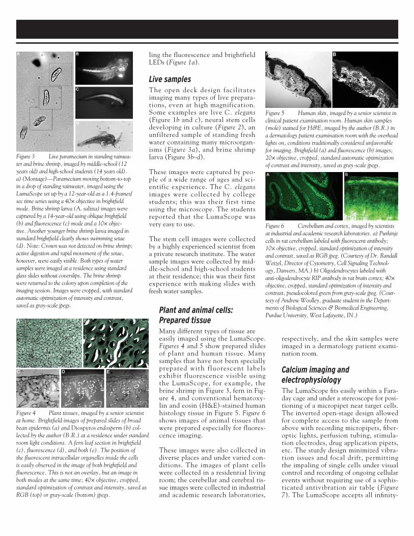
Figure 3 Live paramecium in standing rainwa-ter and brine shrimp, imaged by middle-school (12 years old) and high-school students (14 years old). a) (Montage)—Paramecium moving bottom-to-top in a drop of standing rainwater, imaged using the LumaScope set up by a 12-year-old as a 1.4-frames/sec time series using a 40× objective in brightfield mode. Brine shrimp larva (A. salina) images were captured by a 14-year-old using oblique brightfield (b) and fluorescence (c) mode and a 10× objec-tive. Another younger brine shrimp larva imaged in standard brightfield clearly shows swimming setae (d). Note: Crown was not detected on brine shrimp; active digestion and rapid movement of the setae, however, were easily visible. Both types of water samples were imaged at a residence using standard glass slides without coverslips. The brine shrimp were returned to the colony upon completion of the imaging session. Images were cropped, with standard automatic optimization of intensity and contrast, saved as gray-scale jpegs.
ling the fluorescence and brightfield LEDs (Figure 1a).
Live samplesThe open deck design facilitates imaging many types of live prepara-tions, even at high magnification. Some examples are live C. elegans (Figure 1b and c), neural stem cells developing in culture (Figure 2), an unfiltered sample of standing fresh water containing many microorgan-isms (Figure 3a), and brine shrimp larva (Figure 3b–d).
These images were captured by peo-ple of a wide range of ages and sci-entific experience. The C. elegans images were collected by college students; this was their first time using the microscope. The students reported that the LumaScope was very easy to use.
The stem cell images were collected by a highly experienced scientist from a private research institute. The water sample images were collected by mid-dle-school and high-school students at their residence; this was their first experience with making slides with fresh water samples.
Plant and animal cells: Prepared tissueMany different types of tissue are easily imaged using the LumaScope. Figures 4 and 5 show prepared slides of plant and human tissue. Many samples that have not been specially prepared with fluorescent labels exhibit fluorescence visible using the LumaScope, for example, the brine shrimp in Figure 3, fern in Fig-ure 4, and conventional hematoxy-lin and eosin (H&E)-stained human histology tissue in Figure 5. Figure 6 shows images of animal tissues that were prepared especially for fluores-cence imaging.
These images were also collected in diverse places and under varied con-ditions. The images of plant cells were collected in a residential living room; the cerebellar and cerebral tis-sue images were collected in industrial and academic research laboratories,
Figure 4 Plant tissues, imaged by a senior scientist at home. Brightfield images of prepared slides of broad bean epidermis (a) and Diospyros endosperm (b) col-lected by the author (B.R.) at a residence under standard room light conditions. A fern leaf section in brightfield (c), fluorescence (d), and both (e). The position of the fluorescent intracellular organelles inside the cells is easily observed in the image of both brightfield and fluorescence. This is not an overlay, but an image in both modes at the same time; 40× objective, cropped, standard optimization of contrast and intensity, saved as RGB (top) or gray-scale (bottom) jpegs.
Figure 5 Human skin, imaged by a senior scientist in clinical patient examination room. Human skin samples (mole) stained for H&E, imaged by the author (B.R.) in a dermatology patient examination room with the overhead lights on, conditions traditionally considered unfavorable for imaging. Brightfield (a) and fluorescence (b) images; 20× objective, cropped, standard automatic optimization of contrast and intensity, saved as gray-scale jpegs.
Figure 6 Cerebellum and cortex, imaged by scientists at industrial and academic research laboratories. a) Purkinje cells in rat cerebellum labeled with fluorescent antibody; 10× objective, cropped, standard optimization of intensity and contrast, saved as RGB jpeg. (Courtesy of Dr. Randall Wetzel, Director of Cytometry, Cell Signaling Technol-ogy, Danvers, MA.) b) Oligodendrocytes labeled with anti-oligodendrocyte RIP antibody in rat brain cortex; 40× objective, cropped, standard optimization of intensity and contrast, pseudocolored green from gray-scale jpeg. (Cour-tesy of Andrew Woolley, graduate student in the Depart-ments of Biological Sciences & Biomedical Engineering, Purdue University, West Lafayette, IN.)

FLUORESCENCE MICROSCOPE continued
numerous advantages: ergonomic use, multiple users can share and interact with the real-time image, no subtle con-trols or adjustments are required, and the smaller optical path enables greater sensitivity and rejection of extraneous room light. The small size and ease of use of the device increases the acces-sibility of fluorescence microscopy to a wide range of users in diverse situations.
References1. Tsien, R.Y. The green fluorescent protein.
Ann. Rev. Biochem. 1998, 67, 509–44.2. Kahle, J.S.; Levin, K.R. et al. Luma-
Scope™, an inexpensive, compact, sturdy USB-based inverted fluorescence micro-scope. Presented at the Society for Neu-roscience 40th Annual Meeting, Nov 13, 2010, San Diego, CA.
3. Smith, J.L. The inverted microscope—a new form of microscope. Am. J. Sci. Arts 1852, 14, 233–41.
4. Martin, G.; Agostini, H. et al. Light emit-ting diode microscope illumination for green fluorescent protein or fluorescein iso-thiocyanate epifluorescence. BioTechniques 2005, 38, 204–6.
5. Fossum, E.R. CMOS image sensors: elec-tronic camera-on-a-chip. IEEE Trans. Electron Devices 1997, 44, 1689–98.
The authors are with Etaluma Inc., 1914 Palo-mar Oaks Way, Ste. 150, Carlsbad, CA 92008, U.S.A.; tel.: 760-298-CELL (2355); e-mail: [email protected]. The authors thank the first users for sending examples of their images (more avail-able at www.etaluma.wetpaint.com), their valuable comments on performance of the device, and their creative vision for applications of the microscope.
Figure 7 Calcium signals and electrophysiology, imaged by senior researchers during a university graduate-level electrophysiology laboratory course. a) Modified LumaScope (arrow) embedded with a stereoscope, micromanipulator, and patch-clamp headstage inside a Faraday cage. b) Brightfield image of cultured 5YSY cells with sharp glass electrode for patch-clamping, stimulating with agonist, or loading with calcium indicator dye; 20× standard Meiji objective, no optimization, saved as gray-scale jpeg. c) Field of cells loaded with Fluo-8 calcium indicator dye (TEFLabs, Austin, TX). White arrow indicates single cell stimulated via a glass electrode (coming from top right corner); 40× Plan Apo objective, no optimization, saved as gray-scale jpeg. d) Traces represent calcium signals from multiple cells following bath application of agonist, analyzed using Metamorph® (Molecular Devices Corp., Sunnyvale, CA). Each line represents a signal from a single cell. (Courtesy of Dr. Ian Parker, University of California, Irvine, and Biophotonic Systems [Irvine, CA].)
corrected, Royal Microscopical Soci-ety (RMS) threaded objectives; a high-numerical-aperture Olympus 40× Plan Apo objective (Center Valley, PA) was used in the imaging in Figure 7c.
ConclusionA device was developed at the very sim-plest level that would produce satisfac-
tory images for routine cell inspection, for example, checking cell confluence in a tissue-culture facility or samples at a point-of-care medical clinic. The applications of the LumaScope micro-scope are already expanding as future users envision it in their laboratories, develop applications, and suggest mod-ifications that continue to refine the design. The lack of eyepieces offers